TECHNICAL FIELD
-
The present invention relates to security systems for controlling
access into and within buildings, and more particularly to a security system
incorporating electronic controls.
BACKGROUND OF THE INVENTION
-
Electronic locking systems are commonly used in applications
requiring door locks for a large number of individual rooms, such as hotels,
offices, and multi-housing (e.g., time shares, apartments, student housing,
assisted living facilities). For security purposes, the door lock of each
dwelling should have a different key for successive tenants. Further, the door
lock should be operable by different keys assigned to housing management,
maintenance personnel, roommates, and other people requiring access to a
housing unit.
-
Most electronic locking systems operate via a programmed key that
contains a unique identification code. Each lock also contains authorization
codes corresponding to one or more keys authorized to open the lock. If the
identification number in the key matches the authorization codes in the lock,
the lock will open. As tenants and/or personnel changes, the authorization
codes in the lock are reprogrammed to accept new keys and reject old ones.
-
Although there are security systems for the multi-housing industry
that provide electronic locking systems, these systems often have limited
functionalities and are not flexible enough to accommodate the many types
of access that multi-housing facilities require. Further, currently known
systems still require the housing management to maintain a stock of
preprogrammed keys that will later be assigned to users. Synchronization
between the housing management office and the door locks also requires
labor and time to reprogram the lock to accept new keys and make old keys
inoperative.
-
There is a desire for a security system that offers a wider range of
access options and flexibility than currently known security systems. There is
also a desire for a locking system that can re-key locks more easily than
currently known systems to ensure that information between the management
office and the locks regarding key access can be synchronized easily and
quickly.
SUMMARY OF THE INVENTION
-
Accordingly, one embodiment of the invention is directed to an
electronic access control system including a lock having a lock memory and
a lock circuit that accesses the lock memory, and an electronic key having a
key access code and key data stored thereon. Both the lock memory and the
electronic key have corresponding access codes, and the system is designed
to reprogram the lock memory if the key access code is greater than the lock
access code. The invention is also directed to an electronic key for such an
electronic access system as well as a stand-alone utility device that can be
taken to individual locks for auditing purposes.
-
The invention is also directed to a method for controlling access in a
property having a lock with a lock access code and lock data with an
electronic key having a key access code and key. The method includes
comparing the key access code with the lock access code, denying entry if
the key access code is less than the lock access code, allowing entry if the
key access code is equal to the lock access code, and reprogramming the lock
as well as allowing entry if the key access code is greater than the lock
access code. Reprogramming the lock may include replacing the lock access
code stored in the lock with the key access code as well as replacing any
other data stored in the lock with data stored in the key.
-
As a result, the inventive structure and method allows automatic lock
reprogramming via an access key rather than requiring an operator to
manually reprogram the lock each time the authorization for the lock needs
to be changed (e.g., when a tenant moves out, when a tenant or worker loses
a key, etc.). In one embodiment, new keys can be programmed at a central
office. When the programmed keys are used at a unit, the key automatically
reprograms the lock to lock out any previously authorized keys for that unit.
-
Further, by using a date and time based access code in the electronic
key corresponding to the time the key was made, the system can
automatically determine which electronic keys are the most recently
authorized keys prevent lock access by previously authorized keys and
eliminate the need to keep an inventory of preprogrammed keys. In addition,
the dual communication links in the utility device of the system enables the
utility device to communicate with the system manager as well as
communicate with individual locks, simplifying the system and making lock
auditing easier.
BRIEF DESCRIPTION OF THE DRAWINGS
-
- Figure 1 is a block diagram illustrating the main components of a
security system according to one embodiment of the invention;
- Figure 2 is a representative block diagram of a lock according to one
embodiment of the invention;
- Figure 3 is an exploded view of a reprogrammable key used in one
embodiment of the invention;
- Figure 4 is a chart illustrating data fields defined in the lock and in
the reprogrammable key for operating the lock according to one embodiment
of the invention;
- Figure 5 is a chart illustrating data fields for a query key according to
one embodiment of the invention;
- Figure 6 is a chart illustrating data fields for a limited use key
according to one embodiment of the invention;
- Figure 7 is a flow diagram illustrating how a limited use key is
programmed and used according to one embodiment of the invention;
- Figure 8 is a chart illustrating data fields for a maintenance key
according to one embodiment of the invention;
- Figure 9 is a chart illustrating data fields for a construction key
according to one embodiment of the invention;
- Figure 10 is a flow diagram illustrating a method of programming a
lock according to one embodiment of the invention;
- Figure 11 is a flow diagram illustrating another method of
programming a lock according to one embodiment of the invention;
- Figure 12 is a flow diagram illustrating a method of programming a
common access lock according to one embodiment of the invention;
- Figure 13 is a perspective view of a key encoder according to one
embodiment of the invention; and
- Figure 14 is a perspective view of a utility device according to one
embodiment of the invention.
-
DETAILED DESCRIPTION OF THE EMBODIMENTS
-
The invention is generally directed to a security system and security
system components that can be used in a housing complex, such as a multi-family
dwelling, a condominium complex, apartments, dormitories, or other
similar complex. Figure 1 is a representative diagram illustrating the main
components of a security system 100 according to one embodiment of the
invention. Each component will be explained in greater detail below with
respect to the other figures. Generally, the system 100 includes
reprogrammable keys 102 that are issued to tenants, personnel, and anyone
else requiring access to one or more portions of the housing complex. The
keys 102 can be programmed with different identification codes, access
levels, and even access times to maintain security while still making access
convenient for authorized people.
-
Each area requiring controlled access is equipped with an electronic
lock 104. The lock 104 can be programmed with any desired authorization
codes to ensure that only authorized keys can open the lock 104. The lock
104 may also include a memory that can record a given key's identification
information each time a key 102 is used to access the lock 104. This
information stored within the lock can later be downloaded to generate an
audit trail showing a selected number of transactions, including the time,
date, and type of key used in each transaction.
-
A system manager 106 acts as a central database and clearinghouse
for lock and key data management and for key creation. The system manager
106 may be implemented as software in a personal computer equipped with
an interface 108 that can accept keys for programming data into and reading
data out of the keys 102 as well as receive and display data. In one
embodiment, the system 100 also includes key encoder 110that codes keys
and transfers data to and from the system manager 106. The key encoder 110
be any device that can accommodate the keys 102 and communicate with the
system manager 106 via a communications port (not shown). One example
of a key encoder 110 is shown in Figure 13 and will be described in greater
detail below. Other interface 108 components for communicating with the
system manager 106 may include a computer display, , a keyboard, and/or a
touch screen. The system manager 106 performs all key management
functions via the computer and, when necessary, passes data and commands
to the key encoder 110. A stand-alone utility device 111 may also be
included in the system 100 to act as a portable interface between the system
manager 106 and the locks 104.
-
Each of these system components will be described in greater detail
below with respect to the Figures.
Lock
-
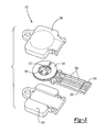
- a. Figure 2 is a representative block diagram illustrating a lock
according to one embodiment of the invention. The lock 104 can be
any known lock, such as one with a cylinder and bolt mechanism,
that can be adapted for electronic control. In one embodiment, the
lock 104 components are placed in a housing 200 and includes a
cylinder and bolt 202 that are movable between an unlocked and a
locked position. The cylinder and bolt 202 are operatively coupled to
an electronic circuit 204 that controls movement of the cylinder and
bolt 202. The electronic circuit 204 is also coupled to a key slot 206
so that the circuit 204 can read and evaluate data on an inserted key
102 and operate the cylinder and blot 202 based on the evaluated
data.
- b. In one embodiment, the lock 104 includes an internal clock 208 that
generates real time date and time information. The date and time
information may be used to control lock access and to act as a
date/time stamp for lock transactions to be included in an audit trail.
The internal clock 208 is first set by the system manager 106; in one
embodiment, the utility device 111 is first connected to the key
encoder 110 so that current (correct) time in the system manager 106
can be transferred through the key encoder 110 to a real-time clock
chip in the utility device 111. The utility device 111 can then be
disconnected from the key encoder 110 and connected to the lock 104
so that the current time in the utility device 111 can be transferred to
the lock's internal clock 208.
- c. Access data and audit trail information, which includes date and time
information, as well as any other information identifying and/or
controlling operation of the lock, such as a lock is stored in a lock
memory 210. The lock memory 210 is accessible by the electronic
circuit 204 so that the circuit 204 can read, for example, data
corresponding to data fields in the keys 102 to control whether a
given key will move the cylinder and bolt 202 into an unlocked
position. The lock memory 210 can be any known readable and
writable memory device.
- d. An RF receiver 212 may also be incorporated into the lock 204 to
receive RF signals from an RF communication chip on the key 102,
making it more suitable for handling excessive daily use without
undue mechanical wear. An AC power source (not shown) should be
coupled to the RF receiver 212 so that the receiver 212 can
continuously scan the area around the lock 104 for an RF signal from
the key 102. Although RF receivers 212 are particularly suitable for
common access locks, which handle excessive daily use, the RF
receiver 212 can be incorporated into any lock 104 at any location
desiring contactless entry.
- e. The lock 104 may also include a switch 214 mounted on the inside
half of the lock so that a tenant can access the switch while inside the
dwelling. The switch 214 can be configured to operate as a passage
switch or a privacy switch, depending on the desired operation. In
one embodiment, the switch 214 is configured via a programming
key and a configure unit key when the lock 104 is installed in a unit.
These processes are explained in greater detail below.
- f. Configuring the switch 214 as a passage switch allows the tenant to
unlock the door from the inside without using a key. In this
embodiment, the switch 214 can be turned between an OPEN
position and a LOCK position. When the switch 214 is in the OPEN
position, circuitry in the lock 104 will place the lock 104 into an
unlocked mode. The lock 104 will remain unlocked as long as the
switch 214 stays in the OPEN position, allowing free access without
a key and ignoring any key that is inserted into the lock (e.g., the lock
will not record any key information if a key is inserted while the
switch is in the OPEN position). If the switch is changed to the
LOCK position, the lock 104 will remain locked unless a valid key is
inserted into the lock 104 or until the switch 214 is changed back to
the OPEN position.
- g. Alternatively, the switch 214 may be configured as a privacy switch
that can deny access to all keys except a valid tenant key or a master
key. In this embodiment, the switch 214 can be moved between a
NORMAL position and a PRIVACY position. When the switch 214
is in the PRIVACY position, the lock 104 can be opened only by a
master key or a valid tenant key and not any other authorized keys
(e.g., keys issued to maintenance personnel). When the switch 214 is
in the NORMAL position, the lock 104 resumes normal operation,
allowing all authorized keys to open the lock. The specific manner in
which the switch 214 is configured to act as a passage switch or
privacy switch is within the capabilities of one of ordinary skill in the
art.
-
Reprogrammable key
-
- a. Figure 3 is an exploded view of a key 102 according to one
embodiment of the invention. The key 102 includes a
reprogrammable computer chip 300 on a circuit board 302 designed
to fit into the key slot 206 of the lock 104. The circuit board 302
includes an electrical contact 304 and one or more electrical traces
306 that connect the contact 304 to the chip 300. The chip 300
includes a programmable memory that stores a selected amount of
data (e.g., 1000 bytes).
- b. The chip 200 is protected by a key bow 308. The bow 308 preferably
is made of a water and temperature resistant material and seals the
chip 300 from harsh environmental conditions. In one embodiment,
as shown in Figure 2, an end portion of the circuit board 302 is
sandwiched between two pieces forming the key bow 308. The key
bow 308 is preferably configured like a conventional key so that it
can be attached to a key ring or key hook.
- c. The key 102 may also include an optional RF communication
function in the chip 300 or a separate RF communication device to
allow the key 102 to act as a proximity key. More particularly, the RF
communication function allows the key 102 to open the lock 104
remotely if the lock 104 has a corresponding RF receiver 212. In the
example shown in Figure 3, a ring-shaped RF antenna 310 surrounds
the computer chip 300 and a charging capacitor 312. The key bow
308 covers and protects the RF antenna 310 and charging capacitor
312 along with the chip 300.
-
Key types
-
- a. One embodiment of the inventive system 100 includes 14 possible
key types, which include: programming key, master key, zone key,
tenant key, inhibit tenant key, inhibit master key, inhibit zone key,
configure all key, configure unit key, configure passage key, query
key, limited use key, maintenance key, and construction key. Each of
these functions will be described in greater detail below.
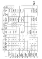
- b. Figures 4 through 6 and 8 are charts illustrating data fields 400 that
may be defined in the computer chip 200 to hold data customizing a
given key's function. These fields are also defined in the lock
memory 210 to hold data to be compared with corresponding data in
the key 102 to control lock operation. In this description, the same
reference numerals will be used to refer to the data fields 400 and the
data held in the data fields for clarity. As can be seen in the charts,
not every data field will be used by every key type. Instead, different
key types will hold data in different combinations of data fields; the
charts illustrate which data fields contain data for particular key
types. Further, the lock circuit 204 will treat data in different key
types differently. For simplicity, the data fields will be generally
described below and then later described more specifically with
respect to each of the different key types. Further, although Figures 4
through 6 and 8 illustrate one specific configuration and order for the
data fields, those of ordinary skill in the art will understand that other
configurations are possible without departing from the scope of the
invention. In one embodiment, each data field comprises one or more
bytes of memory and each function in the key is allocated a specific
number of bytes.
- c. In this particular example, the data is stored in memory locations that
are each one byte long. The first data field in this example is a "data
amount" field 404 that holds data indicating how much memory is
used by the key 102. As will be shown below, different types of keys
102 contain different amounts of data. A "check sum" field 406
represents the number of bytes used in the key 102 to confirm that the
number of bytes received by the lock 104 matches the number of
bytes in the key 102.
- d. The next set of fields stores basic key identification information. The
"distributor code" field 408 and the "customer code" field 410
identify a particular property site in which the key 102 is operational.
More particularly, the distributor code 408 identifies a central
distributor that distributes locks and keys to multiple customer sites,
while the "customer code" field 410 contains information that
distinguishes one customer site from another customer site having the
same distributor.
- e. A "function ID code" field 412 identifies the key type. In one
embodiment, each key type contains a unique, predetermined
function ID code. This function ID code tells the lock circuit 204
which data fields to read, how to interpret them, and how to respond
to the data in the key 102. As a result, the lock circuit 204 will
perform different operations based on the key's type, as identified by
the function ID code.
- f. Next, a "unit number" field 414 contain information about the
specific location where the key will operate (if the field 414 is in the
key 102) or identifying the location of the lock (if the field 414 is in
the lock memory 210). For example, if the key 102 is a tenant key,
the "unit number" field 414 will contain the number of the unit that
the key 102 will open. Similarly, if the key 102 is a zone key, the
"unit number" field 414 will contain the number identifying the zone,
which may encompass multiple units, where the key will operate. In
one embodiment, the value stored in the unit number field 414 in the
lock memory 210 will point to a logical description of the lock used
by the system manager 106. For example, if the lock 104 is assigned
a unit number of 35, indicating that it is the 35th lock to be assigned a
unit number, the system manager 106 may match the unit number
with the logical description of the lock 104 (e.g., "Apartment #534")
and relay the logical description to the end user. Similar matching
between the unit number 414 and the logical lock description can
occur for common access locks, suite locks, and/or other lock
locations.
- g. A passage/privacy switch field 415 configures the lock switch 214 to
act as either a privacy switch or a passage switch, as explained above
with respect to Figure 2.
- h. A "key ID" field 416 provides a unique key ID number. If the "key
ID" field 416 is one byte long, the key may have one of 64 possible
key ID numbers. The "key ID" field 416 may be used to distinguish
different keys that can open the same lock(s) or otherwise have the
same functions. Distinguishing among keys having the same
functions is useful for tracking key usage by two people living in the
same unit, for assigning new keys by incrementing the "key ID" field
416 from the last assigned key ID value 416 , and for disabling old
keys by inhibiting operation of keys having particular key ID values
416, which will be described in greater detail below.
- i. A "sequence number ID" field 418 indicates the order in which the
key was made. The system manager 106 uses data in this field 418 to
properly sequence audit trail transactions
- j. One or more "access code" fields 420 contain date and time data and
may occupy multiple fields to accommodate year, month, day, hour,
and minute data. The access code corresponds to the date and time
that the key was made. This data may be used by the lock circuit 204
to identify the most current keys and ignore keys with less current
access codes. The data in the "access code" field 420 ensures that a
given lock 104 will recognize only the most recently authorized keys
without requiring an operator to reprogram the lock memory 210
itself. In one embodiment, the lock memory 210 stores different
access codes 420 for each key type to ensure that the lock 104 will
operate only for the most recently authorized keys of each type; as
will be explained below, different key types may have different
access codes 420 that are updated at different times.
- k. Next, a "common access lock enable" field 422 holds common access
lock enable data. In one embodiment, the common access lock enable
field 422 is 8 bytes long, and each bit in each byte of the field 422
represents one common access lock. An 8-byte field can therefore
accommodate access data for 64 unique common access locks, each
common access lock having its own unique ID. For example, the
least significant byte in the common access lock enable data fields
422 on a given key 102 may be "0000 0001". This would indicate
that the key 102 can open common access lock 1. Similarly, if the
byte contains "0000 0011", this indicates that the key 102 can open
common access locks 1 and 2. A key with "1111 1111" as its least
significant byte would be able to open common access locks 1
through 8. If all of the bits in the "common access lock enable" field
are 1, then the key 102 can open any common access lock on the
property.
- l. "Inhibit data" fields 424 contain a data array where each bit in the
array corresponds to one "key ID" number. For example, a key
having a key ID of 1 in the "key ID" field 416 is represented by the
first bit in the "inhibit data" array. Each bit will indicate whether its
associated key is active (operational) or inhibited (non-operational).
In one embodiment, if the bit is set to 1 for a given key ID 416, that
key will function in the lock. If the bit is set to 0 for a given key ID,
then that key will not function in the lock. For example, if the least
significant byte of the "inhibit data" field 424 contains "0000 1100"
and all other bytes in the field 424 are also "0", then it indicates that
keys having key IDs 3 and 4 are operational and all other key IDs are
non-operational. The "inhibit data" field 424 allows locks to be
reprogrammed if a key with a given key ID number is lost by simply
changing the bit associated with the lost key's ID number in the key
102 and then uploading the inhibit data information 424 on the key to
the lock member 210, as will be described in greater detail below. In
one embodiment, the "inhibit data" field 424 is 8 bytes long,
accommodating 64 different key IDs.
- m. "Operation date/time" fields 425 indicate the dates and times during
which the key will be operational. This information is compared with
the date/time data in the lock memory 210 to determine whether the
key is authorized to open the lock 104 at a given date/time. By
indicating the time window during which the key will be operational,
the key 102 has a built-in expiration, ensuring further security. The
operation date/time information can, for example, prevent a
previously authorized user from accessing locks after the
authorization period is over or allow access to a common area only
during a selected time window. As shown in the Figures, not every
key type has data in every field. Unique features of each key type's
operation will now be explained.
- n. A programming key 426 is used to program a lock to accept valid
master keys and zone keys, so it contains both access codes 420 and
inhibit data 424 for both a master key 428 and a zone key 428 as well
as its own programming key access code 420 to ensure that the lock
104 will only accept the most recently activated keys. However,
because the programming key 426 is not associated with, for
example, one particular zone or unit, the unit number field 414
remains unused in the programming key 426. More details of the
programming key's operation will described later with respect to
Figure 8.
-
Normal access keys
-
- a. Normal access keys are any keys that are used to open one or more
locks. Access keys include master keys 428, zone keys 430, and
tenant keys 432. Access keys have similar formats and operations, as
will be noted below. Although limited use keys (described under
"Specialty keys") also open one or more locks, their operation is
somewhat different than master, zone, and tenant keys and will be
described separately.
- b. The master key 428 is programmed to open any lock 103 having a
distributor code 408, customer code 410, and access code (date/time
stamp) 420 matching the master key 428 being inserted into the lock
104 as well as valid master key inhibit data 424 for the master key ID
416 of the inserted key. In one embodiment, all active master keys
428 have the same access code 420 so that the door locks only need
to store one master key access code 420 even if the active master
keys 428 themselves were made at different times. To do this, the
system manager 106 saves the date/time stamp given to the first
master key made and uses this date/time stamp as the access code in
subsequent master keys.
- c. Each master key may have a unique key ID 416 to allow a given
property to have more than one uniquely-identified master key. In
one embodiment, if the "key ID" field 416 is one byte long, 64
possible unique master key ID's are possible. A lost master key may
be replaced by a new master key having a different key ID 416; as
noted above, creating a replacement key also involves changing the
array stored in the "inhibit data" field 424 to deactivate the key ID
416 of the lost master key. Regardless of the reasons why the array in
the "inhibit data" field 424 is changed (e.g., because of a lost key or
because of a new access code), the new master key 428 having the
new "inhibit data" array 424 is inserted into every lock 104 requiring
accessibility by the master key to load the new array into the lock
memory 210. This ensures that only keys having active key ID's 416
will be able to open the lock 104.
- d. If over time the number of master key ID's is used up (e.g., indicated
by the lack of available active bits in the "inhibit data" field 424), the
master keys 428 may be reprogrammed to allow creation of more
master keys by changing the access code 420 of each active master
key for the property and inserting the master key with the new access
code into each lock on the property. Inserting the new master key
uploads the new access code 420 into the locks, locking out all
previously made master keys having the earlier access code. If the
access code 420 is updated, the "inhibit data" field 424 should also be
changed to reflect the key IDs of the active master keys having the
new access code 420.
- e. Like the master key 428, the zone key 430 opens any lock 104 having
a matching distributor code 408, customer code 410, access code 420,
and valid key inhibit data (in this case, valid zone key inhibit data)
424. However, the zone key 430 also includes a zone number in the
"unit number" field 414. This zone number 414 that must match the
zone number stored in the lock memory 204 for the lock 104 to open.
Further, as shown in Figure 4, the zone key 430 will contain data in
the common access lock enable field 422 to control which common
access locks the zone key 430 can open. Like master keys 428, active
zone keys 430 may also have the access code 420 of the first zone
key made even if other zone keys are made at different times. This
allows the locks to store only one zone key access code 420, making
it convenient to add and replace zone keys 420 without having to
change the zone key access code 420 and thereby affect the operation
of other valid zone keys.
- f. Tenant keys 432 have information similar to zone keys 430 except
that they contain a unit number in the "unit number" field 414. To
open a lock 104, the unit number 432 in the tenant key 432 must also
match the unit number stored in the lock memory 210 along with
matching all the other lock data (e.g., distributor code 408 and
customer code 410). Further, the tenant key access code 420 stored
in the lock memory 210 ensures that the lock 104 will accept only the
most current tenant keys 432 that are explicitly given access by the
system manager 106. Tenant keys 432 having less current access
codes than the access code stored in the lock memory 210 and/or
keys that have inactive key ID's 416 according to the array stored in
the "inhibit data" field 424 will not be able to open or reprogram the
lock 104. In one embodiment, if the tenant key access code 420 is
more recent than the tenant key access code stored in the lock
member 210, the lock member 210 will replace its own tenant key
access code with the more recent access code 420 on the key, thereby
automatically reprogramming the lock 104 to accept the new tenant
key 423 without manual reprogramming of the lock 104 itself. Figure
9 illustrates one way in which the tenant key can be used to
reprogram a lock in greater detail using a programming key. The
common access lock enable field 422 in the tenant key 432 operate in
the same manner as explained above with respect to zone keys 420.
-
Inhibit keys
-
- a. Inhibit keys, such as an inhibit master key 434, inhibit zone key 436,
and inhibit tenant key 438, are used to prevent one or more keys from
opening the lock 104. More particularly, the inhibit keys can instruct
a lock 104 to block a key that otherwise has a current access code 420
and matching identification information (e.g., distributor code 408,
etc.). This prevents the blocked key from operating without blocking
other current keys having the same access code 420 as the blocked
key. As noted above, multiple current keys that are otherwise
identical can be distinguished from each other by their key ID
numbers 416. By changing the inhibit data array 424 in the lock
memory 210, the operator can control which specific key IDs 416 can
open the lock.
- b. Inhibiting a key having a given key ID 416 can be conducted by
creating an inhibit key 434, 436, 438 containing the new inhibit data
array 424 and inserting the inhibit key 434, 436, 438 into the affected
lock(s) 104. The lock circuit 204 will record the new inhibit data
array into the lock memory 210 and lock out access to the inhibited
key IDs indicated in the inhibit data array 424.
- c. If the operator wishes to inhibit all active keys, the operator may,
through the system manager 106, update the access code in a key
with the current date and time and reset all of bits in the inhibit data
array to "1", thereby allowing access to all keys having the new
access code. This is more efficient than changing the inhibit data
array 424 to block all active keys and provides room in the inhibit
data field 424 for creating future keys. Inserting the key 102 with the
new access code 420 into each lock memory 210 will block all keys,
regardless of type, with the older access code and reset the lock to
allow keys having the updated access code 420 to unlock the lock
104. More particularly, the lock circuit 204 will detect that the access
code 420 in the key 102 is more recent than the access code 420
stored in the lock memory 210 and replace the lock access code 420
with the access code 420 on the key.
- d. If a lock 104 is accessible by more than one key 102 and if the
operator has access to a key having the same function as the key to be
inhibited and a key ID 416 that the operator wishes to keep active, the
operator may avoid having to reprogram the lock 104 with a
specialized inhibit key altogether. Instead, the operator may allow the
user of the active key to reprogram the lock automatically the next
time he or she inserts the active key into the lock. To do this, the
operator may take a current active key and create a duplicate key
having identical key data except for an updated inhibit data array 424
to block the inhibited key. When the duplicate key is inserted into the
lock 104 and the lock circuit 204 verifies that the duplicate key is a
valid, active key, the lock circuit 204 will record the updated inhibit
data array 424 into the lock memory 210, reprogramming the lock
104. As a result, the inventive system allows updating of the
information in the lock memory 210 simply by rekeying a user's key
102, without requiring any separate reprogramming of the lock
memory 204 through manual means.
- e. The inhibit tenant, inhibit zone, and inhibit master keys operate in
generally the same manner and differ primarily in the area identified
by the "unit number" field 414 (e.g., whether the unit number 414
identifies a zone or unit, etc.). If the inhibit key is an inhibit master
key, the unit number field 414 is left blank because, as explained
above, master keys themselves do not contain data in the unit number
field 414.
-
Configuration keys
-
- a. Configure all keys 440, configure passage keys 442, configure unit
keys 444, and configure suite keys 446 are used to program
information into the lock memory 210. The configure all key 440 is
primarily used during lock manufacturing and is not used by an end
user. As shown in Figure 4, the configure all key 440 does not
contain any specific information; instead, virtually all of the data
fields are left blank. When the configure all key 440 is inserted into
the lock, it clears the distributor code 408, customer code 410, unit
number 414, key ID 416 and any audit trail data from the lock
memory 210 and sets the lock to "factory mode". Locks in "factory
mode" are only accessible with a construction key, which will be
described in greater detail below.
- b. The configure passage key 442 is used to program a passage number
into a lock, while the configure unit key 444 is used to program a unit
number and other lock characteristics (e.g., the way the
privacy/passage switch 214 will operate) into a lock 104. The way in
which programming takes place generally is explained in greater
detail below with respect to Figures 9 and 10. The configuration keys
themselves simply contain data to be transferred to the lock memory
210. For example, the configure unit key 444 may contain the
distributor code 408, customer code 410, unit number (in unit number
field 414), tenant key access code 420, and tenant key inhibit data
424 as information to be programmed to the lock memory 210, while
the configure passage key 442 contains the distributor code 408,
customer code 410 and the common access lock number (in unit
number field 414).
- c. A variation of the configure unit key 444 is a configure suite key 446.
Suites are areas having more than one unit. The configure suite key
446 programs a suite number into a lock 104. The data information is
the same as the configure unit key 444 except that an additional data
field stores the number of units within the suite (not shown).
Otherwise, the configuration process for configure unit keys 444 and
configure suite keys 446 are identical. Locks configured by the
configure suite key 446 operate in the same way as locks configured
by the configure unit key 444.
-
Specialty keys
-
- a. Query keys 500, limited use keys 600, maintenance keys 650, and
construction keys 700 are unique keys designed for specialized
functions.
- b. Figure 5 illustrates data fields 400 in one embodiment of a query key
500. The query key 500 is used to download an audit trail from the
lock memory 210 and can be used in any unit at any site; as shown in
Figure 5, the query key 500 does not contain a distributor code or
customer code linking the key to a particular site. Instead, the query
key 500 itself includes only the data amount 404, check sum 406 and
function ID 412 identifying the key as a query key 500. Further,
unlike the other keys described above, the data fields in the query key
500 do not themselves contain any data associated with a specific key
or lock. Instead, the fields are designed store the audit data from the
lock memory 210 in an organized format. Downloading data from the
lock memory 210 to the query 500 simply requires inserting the
query key 500 into the lock 104 and keeping the query key 500 in the
lock 104 until the downloading operation is complete. In one
embodiment, the lock 104 may have audible and/or visual signals
indicating completion of a download operation.
- c. For simplicity, Figure 5 shows a query key 500 that holds an audit
trail containing two transactions, but in practice query keys 500 can
hold many more transactions. In one embodiment, the lock memory
210 first downloads basic identification information to the query key
500 before downloading the audit trail itself, such as the lock's unit
number 502, the lock's zone number 504 (verifying that the lock is
properly zoned), the lock's software version number 506, if desired,
the lock's status byte 508 (verifying the lock's battery operation and
clock chip status), the lock's current date and time 510 according to
the lock's real time internal clock 208, and the number of transactions
in the audit trail 512.
- d. In this example, each transaction in the audit trail will contain the
function ID 514a, 514b of every key used to open the lock 104, and
transaction data 516a, 516b, such as the key ID number identifying
the specific key used, a key sequence number, and a date/time stamp
indicating the date and time, according to the lock's internal clock
208, at which the transaction occurred. Other information or selected
combinations of information can be included in the transaction data
516a, 516b without departing from the scope of the invention.
- e. Limited use keys 600 are designed to open doors for a limited time
period during one calendar day. Limited use keys 600 may be created
and issued to, for example, maintenance personnel authorized to
access a given unit only for a limited time period. In one
embodiment, the limited use key 600 is designed to allow access only
on the day that the limited use key 600 is made, even if the operator
programs the key for a longer time period.
- f. Figure 6 illustrates fields in a limited use key 600 according to one
embodiment of the invention. In this embodiment, the limited use key
600 has a distributor code 408 and customer code 410 like the other
keys described above to identify the property at which the limited use
key 600 can be used. The key 600 also includes a limited use key
access code 420, which must be larger (more recent) than a limited
use access code stored in the lock memory 210 for the lock 104 to
open. The field also includes common access lock enable fields 422
representing common access locks that the limited use key 600 is
authorized to open. A series of unit number fields 602 indicates the
unit numbers that the limited use key 600 is authorized to access.
This allows the key holder to access multiple units with one limited
use key 600.
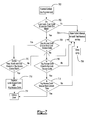
- g. Figure 7 is a flow diagram illustrating the operation of the limited use
key 600. Because limited use keys 600 require tighter security
measures, authorizing access for a limited use key 600 is more
complicated than other key types and goes beyond simple code
matching. If the operator wishes to allow the limited use key 600 to
open a given unit only once, the current key management system
access code will be programmed into the limited use key 600. When
the limited use key 600 is inserted into the lock 104 for the first time
(block 700), the lock circuit 204 checks whether the distributor code
408, customer code 410, and unit number 414 in the limited use key
600 match the corresponding codes stored in the lock memory 210
(block 702). If the codes do not match at this point, the lock circuit
204 records the failed entry attempt in the lock memory 210 (block
704) and denies entry to the unit (block 706).
- h. Next, the lock checks whether the limited use key access code 420 is
larger than the limited use access code stored in the lock (block 708).
Note that the limited use access code in the lock memory 210 at this
time will be the limited key access code of a previously used limited
use key for reasons explained below.
- i. If the key's access code is larger than the lock's access code, the lock
then checks whether the year, month and day portion of the key's
access code matches the date in the lock's real time clock (block 710).
If so, the lock circuit 204 will then compare the time portion of the
key access code with the current time in the lock's internal clock
(block 712). If the time portion in the key is larger than the current
time indicated by the lock, the lock circuit 204 replaces the lock
access code stored in the lock memory
- j. If the same key is reinserted into the lock, the lock will first see that
the access code in the key is the same as the access code in the lock
(because the lock recorded the key's access code at block 712).
Because the two access codes match (block 716), the lock circuit 204
will then compare the key's access code with the current time in the
lock's real time clock (block 718). If the key's access code is smaller
than the current time, the lock will not open (blocks 704 and 706).
This process ensures that a limited use key cannot be used more than
once on the same lock.
- k. If the operator wishes to allow access to a unit over a selected time
period, the limited use key access code 420 may be programmed to
reflect a time window during which the limited use key 600 is
operational. In one embodiment, the limited use key 600 is
programmed with a current key management system access code plus
a selected time value (e.g., 3 hours). This ensures that the key's access
code will remain larger than the current time in the lock's real time
clock for the selected time period even if the key is inserted
repeatedly into the lock. As long as the key's access code is larger
than the current time, the lock will open (block 718). In one
embodiment, if the key includes multiple unit numbers, any time
restrictions programmed into the limited use key 600 applies to all
units. For example, if the limited use key 600 does not specify a time
window and is programmed to open three units, the key 600 can open
each of the three units only one time. If the key does specify a time
window (e.g., 3 hours), the key 600 can open all three units any
number of times for 3 hours after the key 600 was made.
- l. In one embodiment, the limited use key 600 also includes extra fields
602, 604, 606 for storing an internal audit trail. Every time the
limited use key 600 is inserted into a lock, regardless of whether the
key actually opens the lock, the key 102 stores the current date/time
stamp of the lock, the lock's unit number and the lock's status
information in an audit trail memory block 604 on the key 600. An
audit trail pointer 606 indicates to the lock circuit 204 where to write
the next audit transaction on the limited use key 600. When a worker
returns a limited use key 600 to the operator, the downloaded data
from the key indicates which units the worker entered, the time at
which the worker entered the units, any common access locks opened
by the key, and whether the worker tried to access other units. The
lock status information stored on the key in the audit trail memory
block 604 also reflects lock battery condition, integrity of the real
time clock chip in the lock, lock traffic, and other factors relating to
the lock's condition.
- m. Figure 8 illustrates a diagram of a maintenance key 650 according to
one embodiment of the invention. Maintenance keys 650 can be used
to check the condition of a lock 104. In one embodiment, each
maintenance key 650 can store information from up to 70 different
unit and/or suite doors. Multiple maintenance keys 650 can be made
and issued if more doors are to be checked with the key 650.
- n. The maintenance key 650 contains the data amount 404, check sum
406, distributor code 408, customer code 410 and function ID 412.
The maintenance key 650 then indicates the number of lock records
652 stored on the key. The first record in the maintenance key 650 is
then indicated by the lock type 654a (e.g., unit lock or suite lock) and
the data 656a for that lock. The lock data 656 can include the unit or
suite number corresponding to the lock, current voltage status of the
lock's battery, the number of times the lock has been opened/closed,
the lock's software version, and the current date/time data for that
lock. The lock type 654b for the second lock marks the start of the
second record in the maintenance key, and the data 656b for the
second lock. Records for additional locks are saved on the
maintenance key in the same manner as the first two records.
- o. Construction keys 750, as shown in Figure 9, are used to open locks
that are in factory mode (i.e., locks that have not been programmed
with distributor or customer codes). Construction keys 750 will
contain the minimum data used for key operation, such as the amount
of data on the key 404, check sum 406, and the function ID 412. As
explained in greater detail below, the construction key 750750 will be
inoperative once a programming key 426 has been inserted into the
lock 104.
-
Lock programming
-
- a. As noted above with respect to Figures 4 through 6 and 8, each key
102 stores data in different data field combinations. The lock 104 will
therefore respond differently to different keys. Figures 9 and 10 show
two specific examples for programming the lock 104 to accept and
reject selected keys 102. Generally, the lock 104 will deny access if
the access code in the key is smaller than the corresponding access
code in the lock, allow access if the key access code and the lock
access code are the same, and allow access and record the key access
code and any updated data in the key into the lock 104 if the key
access code is greater than the lock access code. In all cases, the lock
104 will operate based on the comparison between the key access
code and the lock access code.
- b. Figure10 is a flow diagram illustrating one method of programming a
new lock 104 using the programming key 426. Programming the lock
instructs the lock to accept selected access keys. Generally, the
programming key 426 assigns a distributor code 408, a customer
code 408, master key 428 information and zone key 430 information
to a new lock 104. If the lock 104 is initially received directly from
the factory, it will be in "factory mode" and can be opened only with
a construction key (block 650). This ensures that construction
workers can obtain access to all areas of the property and not
accidentally lock out other workers.
- c. Once the locks 104 for a given site are installed, the programming
key 426 is inserted into each lock 104 to dedicate the lock to that site
(block 660). More particularly, all of the information in the
programming key 426 shown in Figure 4 is written to the lock
memory 210 so that the lock 104 can no longer be opened by a
construction key or any keys associated with other sites (block 662);
at this point, the locks 104 are dedicated to the site corresponding to
the distributor code 408 and customer code 410. Because the
programming key 426 initializes a lock to accept both master key 428
and zone keys 430, the programming key 426 contains access codes
and inhibit data 420, 424 for both master keys and zone keys as well
as its own programming key access code. The access codes 420 for
both master keys and zone keys stored in the programming key 426
ensure that the lock 104 will be programmed to accept only master
keys and zone keys having the current access code 420.
- d. After the programming key 426 has been inserted into a "factory
mode" lock 104 for the first time (block 660), the lock 104 can be
opened only by a master key 428 or a zone key 430 having codes
corresponding with the information stored in the lock 104. The lock
104 is then programmed using a programming key 426 in conjunction
with the configure unit key 444 so that the lock will accommodate
tenant keys 432. To program the lock 104 and dedicate it to a
particular unit, the programming key 426 is inserted into the lock
(block 664). The lock circuit 204 first compares the programming key
access code of the inserted programming key with the corresponding
access code in the lock memory 210 (block 666). If the access code
on the key is less than the corresponding access code in the lock 104,
it indicates that the programming key is a deactivated key with an old
access code. As a result, the lock circuit 204 will deny access to the
inserted programming key (block 668).
- e. If the inserted programming key contains newer programming key
access data than the programming key access data stored in the lock
memory 210, the lock circuit 204 will store the data from the inserted
programming key and inhibit the previous programming key data
(block 670), automatically updating the lock 104 to accept the new
programming key and reject all other programming keys. More
particularly, the lock memory 210 replaces its stored access code with
the more recent access code 420 on the programming key 426 to lock
out any programming keys with older access data (i.e., programming
keys that were made earlier than the newest programming key). Data
transferred from the programming key 426 to the lock 104 in addition
to the master key access data 420 include the distributor code 408,
customer code 410, master key inhibit data 424, and, if desired,
daylight saving time data to control the internal clock 208 in the lock
104.
- f. Once a valid programming key is inserted into the lock 104, the lock
circuit 204 sets a time window (e.g., 20 seconds) during which the
lock memory 210can be programmed with the information stored on
any valid configure unit key inserted into the lock 104 to dedicate the
lock 104 to a particular unit.
- g. If a configure unit key is inserted into the lock (block 672) during the
time window (block 674), the key data on the configure unit key will
transfer to the lock memory 210 (block 676). Once this data is
transferred, the lock 104 is ready for access by a tenant key assigned
to that unit. In one embodiment, the data transferred to the lock
includes the distributor code 408, access code 410, customer code
410, unit number 414 (e.g., corresponding to the unit and the zone),
privacy/passage switch configuration data 415, and the zone access
code 420.
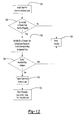
- h. Figure 11 illustrates a process where the lock is reprogrammed with
new tenant data (e.g., if the unit is rented to new tenants). To
reprogram a unit lock with new tenant data, the tenant key is first
inserted into the lock (block 678). The lock circuit 204 compares the
tenant key data stored in the lock (e.g., access code 420 and inhibit
data 424), if any, with the corresponding data in the inserted key to
see if the inserted key has a greater access code than the tenant key
access code 420 stored in the lock (block 680).
- i. If the tenant key access code in the key 420 is greater than the tenant
key access code in the lock memory 210 (indicating that the inserted
tenant key is more recent than any tenant key that had been
previously inserted into the lock 104), the lock circuit 204 records the
tenant key access code from the inserted key into the lock memory
210 (block 682) and unlocks the door (block 684). This updates the
lock to accept the most recently made tenant keys and block all
previously made tenant keys, which will have a smaller tenant key
access code than the access code now stored in the lock memory 210.
- j. More particularly, the lock memory 210 records the tenant key access
code 420 of the inserted tenant key 430 as its own tenant key access
code 420; because the tenant key access code 420 reflects the date
and time the tenant key 430 was made, the lock circuit 204 will be
able to distinguish a newly-authorized tenant key from previous,
currently unauthorized tenant keys and reprogram the lock memory
210 automatically without any additional instructions or
reprogramming from the security system operator.
- k. As with other key types, the same tenant key access code 420 may be
used for multiple tenant keys even if the keys were actually made at
different times. To ensure that only active tenant keys 432 can open a
lock 104, the operator can control the array stored in the "inhibit
data" field 424 via the system manager 106 to identify which key ID's
416 are valid. In one embodiment, the tenant key access code 420 is
assigned to be the date and time at which the first tenant key was
made for a given unit. Each time a new tenant key 432 is made after
that (e.g., to replace a lost key or to make an extra key), the operator
will program, via the system manager 106, the access code 420 of the
first tenant key into the new key and change the inhibit data array 424
to activate the key ID 416 of the new key and/or deactivate the key
ID 416 of the lost key. This eliminates the need for any additional
lock reprogramming via the system manager 106, the programming
key, or any other manual means to add the new authorized key and/or
block the lost key; instead, the newly-made key will automatically
reprogram the lock memory 210 when it is inserted into the lock 104.
- l. In one embodiment, the tenant key access code 420 is changed in the
system manager 106 only when a tenant moves into or out of a unit,
while the tenant key inhibit data array 424 is changed when an
existing tenant loses a key or wants an additional key. This ensures
that activation of new keys and deactivation of lost keys does not
inadvertently deactivate other keys that are still valid. In both cases,
the lock memory 210 will be reprogrammed only if the key access
code is equal to or greater than the lock access code.
- m. The programming key 426 and configure unit key 444 are therefore
useful when programming a lock 104 for the first time, programming
multiple locks 104 at one time. However, as shown in Figure 11, a
new tenant key 432 can be inserted into an individual lock 104 to
reprogram the lock 104 automatically without using the programming
key 426 at all. In other words, the lock 104 can lock out old tenant
keys and accept new tenant keys simply by inserting the new tenant
key alone into the lock 104;the lock circuit 204 will automatically
recognize a newly authorized tenant key by its tenant key access code
420, as explained above, without any help from the programming key
426.
- n. If the lock 104 will be used a large number of times per day, such as
in a common access door, exercise room, etc., the lock 104 may be a
common access lock having components (e.g., different electronic
hardware, physical housing, and/or internal operating software) that
can handle heavier usage and record a larger number of lock
transactions.. The lock memory 210 for a common access lock may
include a common access lock identification number to distinguish a
particular common access lock from other common access locks.
- o. Figure 12 is a block diagram illustrating a method for programming a
common access lock using a tenant key 432. Because common access
locks must be accessible by multiple tenant keys, and because valid
tenant keys are often added and removed, the inventive system can
automatically update the common access lock simply by recording
updated information in new tenant keys 432 without requiring the
operator to program the common access lock directly. Instead, when
a new tenant key 432 is made, the operator may select via the user
interface 108 of the system manager 106 which common access locks
the tenant key 432 will be able to open. This data in stored in the
common access lock enable field 422.
- p. When the tenant key 432 is inserted in a given common access lock
(block 700), the circuit 204 in the common access lock will first
check the distributor code 408, customer code 410 and the function
ID 412 in the key to verify that the key is a tenant key for the
property being accessed (block 702). If not, the common access lock
denies access (block 704).
- q. The common access lock circuit 204 then checks the unit number 414
(in this case, the unit number) and the key ID 416 of the tenant key,
which tells the circuit 204 which bit in the "tenant key inhibit data"
field 424 stored in the lock memory 210 contains the bit
corresponding to that particular tenant key 432 (block 706). If the
tenant key inhibit data in the lock memory 210 indicates that the
tenant key 432 has been inhibited (block 708), the common access
lock will not open (block 704) and will not store any data from the
key into the lock memory 210. Conversely, if the common access
lock inhibit data stored in the lock memory 210 indicates that the
inserted tenant key is active, the common access lock will open
(block 710), compare the tenant key inhibit data on the tenant key
with the corresponding inhibit data stored in the lock memory 210,
and record the tenant key inhibit data on the key into the lock
memory 210 (block 712).
- r. Alternatively, the common access lock may be programmed using the
utility device 111, particularly if multiple common access locks will
be programmed at one time. To do this, common access lock data for
the locks can be updated via the system manager 106 and
downloaded from the system manager 106 to the utility device 111
via the key encoder 110. The updating process may include, for
example, identifying all keys allowed to open the common access
lock. The utility device 111 can then be taken to one or more
common access locks, and the data in the utility device 111 can be
uploaded to the common access lock. Because each common access
lock has a unique identifier, the common access lock will be able to
determine which data in the utility device 111 corresponds with a
particular lock 104. Once the updated data is uploaded into the lock,
the common access lock is ready to accept all valid keys identified
through the system manager 106.
- s. Although Figures 9 through 12 illustrate specific ways that the lock
104 can be programmed, one of ordinary skill in the art will
understand that the general programming process (e.g., updating
access codes, updating inhibit data) can be applied to any key type
and is not limited to the examples shown in the Figures.
-
System manager, key encoder and utility device
-
- a. As noted above, the system manager 106 (Figure 1) may be
implemented as software in a personal computer. In one embodiment,
the system manager 106 includes menus that allow a user to add,
delete or modify employee data, add, delete or modify tenant data,
customize the software to the housing facility's specific parameters
(e.g., set room numbers, zone groupings, common access locks, etc.),
program keys, read keys to log them back into the system or
download stored data on the keys, upload data to and download data
from the utility device, verify key contents, and print reports showing
any combination of desired data (e.g., key histories, lock access
history, employee report, activity reports, transaction reports, etc.) via
the user interface 108. In one embodiment, the system manager 106
stores all of its information and activities to one or more databases
800. For protection, the system manager 106 may allow entry of
usernames, passwords, and different levels of access to control that
can create particular types of keys and print reports. The specific
manner in which the system manager 106 carries out these functions
is within the capabilities of one of ordinary skill in the art based on
the security system parameters described above.
- b. system manager. As shown in Figure 1, the system 100 may include a
key encoder 110 that acts as the interface between the keys 102 and
the system manager 106 as well as the interface between a utility
device 111 and the system manager 106.Generally,
- c. Figure 13 illustrates the key encoder 110 according to one
embodiment of the invention. In one embodiment, the key encoder
110 includes a housing 850, a display 854 and a key slot 856 that can
accommodate the circuit board 302 of the key 102. The key encoder
110 communicates with the system manager 106 via any known
communication link (not shown). In one embodiment, the key
encoder 110 is kept connected to the system manager 106 at all times.
- d. Programming keys requires the key encoder 110 to be connected to
the system manager 106 via any known communication link (not
shown). To program a key 102, the system manager 106 first asks the
user to select the type of key to be made. The specific information
requested by the system manager 106 will correspond to the type of
key being created. For a tenant key, for example, the user places the
key into the key slot 856 of the key encoder 110 and input tenant and
housing unit identification information into the system manager. In
one embodiment, the operator inputs a valid housing unit number that
the key will open (it is assumed that each tenant key will open the
lock for only one unit number), tenant identification information
(e.g., name) that can be used to track key usage via the audit trail, and
any common access locks that the key should open.
- e. Creating a limited use key, on the other hand, will require the system
manager 106 to request additional information that will eventually be
stored in the appropriate data fields specific to that key. For example,
to create a limited use key for maintenance access, the system
manager 106 will ask the operator to input a valid housing unit
number, the duration that the key will work (e.g., 2 hours from the
time the key is made), and a code corresponding to the reason the
limited use key is being made. In one embodiment, it is assumed that
the limited use key will be returned the same day that it is issued,
after the maintenance request is fulfilled. The specific information
and the manner in which the information is stored in the limited use
key 600 is described above with respect to Figure 6.
- f. To log returned keys, the operator selects a key return function in the
system manager 106 and inserts the key into the key slot 856,
allowing the key encoder110 to read the data from the key and send
the read data to the system manager 106. The system manager 106
then displays the key's information, allowing the user to verify that
the key being returned is the intended key. If not, the operator can
notify the system manager that key in the key reader should not be
returned and remove the key, leaving all of the data in the key intact
and keeping the "active" status of the key in the system manager. If
the operator wishes to continue with the key return transaction after
verifying the key data, the system manager 106 logs the returned key
information and erases the access data from the key 102. The erased
key can then be reprogrammed and reused in the future.
-
Auditing a lock
-
- a. The lock memory 210 in the lock 104 (Figure 2) will store the
following information each time a key 102 is inserted into the lock:
(1) the time and date of the insertion; (2) the name/ID of the key and
any related user identification data; (3) the type of key used; (4) the
key's access code (date/time data).
- b. When the audit trail is generated, the audit trail may also list the
following information: (1) the last time the lock was powered up; (2)
each time a utility device 110 is inserted into the lock 104; (3) each
time a query key 500 is inserted in the lock 104.
- c. The way in which auditing can be conducted using a query key 500 is
explained above with respect to Figure 5. Query keys are convenient
because they can be made at any time and stored for later use.
However, query keys are designed to retrieve the audit trail
information from only one unit lock. The greater storage capacity of
the utility device 111 allows the operator to download data from
multiple locks (e.g., three unit locks, one common access lock, etc.).
Once the query key 500 or the utility device 111 become completely
filled with audit trail information, the information needs to be
emptied to the system manager 106 to make room for more
information.
- d. Figure 14 illustrates the utility device 111, which can be used for
auditing multiple locks, according to one embodiment of the
invention. The utility device 110 is a portable, stand-alone device that
can be initialized by the system manager 106 via the key encoder 110
to have one or more selected functions, such as a time synchronizing
device (to synchronize the locks 104 with the system manager 106),
an audit trail retrieval device, and/or a common access lock
programmer (to transfer an information database containing
information for multiple tenants to a common access lock).
- e. In one embodiment, the utility device 111 is a battery-operated device
that contains a microprocessor (not shown) held in a housing 860
having an alpha-numeric display 862. The utility device 111 includes
a plug 864 that can fit into the key slot 206 of the lock 104. The plug
864 can also fit into the key slot 856 of the key encoder 110 so that
the utility device 111 can communicate with the system manager 106
through the key encoder 110, as noted above. The utility device 111
may also include a real-time clock chip and a back-up power supply
(not shown) so that the utility device 111 will maintain correct date
and time data as dictated by the system manager 106.
- f. The utility device 111 preferably has a greater memory capacity than
a query key 500 to allow it to hold audit trail data for multiple locks
104. Further, the utility device 111 can be updated with the current
time, date, and/or key data from the system manager 106 and then
taken to a lock 104 to update the internal clock 208 in the lock, as
explained above. In short, the utility device 111 acts as the interface
between the lock 104 and the system manager 106, communicating
via the key encoder 110.
- g. To download data from the lock memory 210 of a given lock using a
utility device, the utility device 111 is first configured by the system
manager 106 as an audit trail retrieval device taken to the lock(s) to
be audited. Note that because the utility device 111 must be
configured by the system manager 106 each time it to be used for
lock auditing, it is somewhat less convenient to use than the query
key 500.
- h. The plug 860 of the utility device 110 is inserted into the key slot 206
of the lock 104 to be audited. If desired, the utility device 110 may be
configured to display a message indicating that the download is
taking place. When the audit trail data has been completely
downloaded from the lock 104 into the utility device 110, another
message may be displayed indicating that the download is complete.
- i. If the operator wishes to download an audit trail from another lock
104, the operator can simply insert the plug 860 of the utility device
111 into another lock 104, without returning the utility device 111 to
the system manager 106 to download the previous audit trail. Once
all of the desired locks have been audited, the plug 864 of the utility
device 111 is inserted back into the key slot of the key encoder 110
so that the system manager 106 can upload the audit trail stored in the
device 111 for long-term storage, display and/or printing. Because
the audit trail data includes lock identification data, the utility device
111 is able to track which audit trail corresponds to which lock 104.
- j. As a result, the inventive system provides an access control system
that provides a wide range of access options. The inventive system
also can combine the key making and lock rekeying functions by
automatically rekeying a lock when a newly-made key is inserted into
the lock, eliminating the need to rekey the lock manually. Other
advantages of the inventive system and its various components will
be apparent to those skilled in the art.
-
-
It should be understood that various alternatives to the embodiments
of the invention described herein may be employed in practicing the
invention. It is intended that the following claims define the scope of the
invention and that the method and apparatus within the scope of these claims
and their equivalents be covered thereby.