EP1449552B1 - Syringe barrel and cylinder holder - Google Patents
Syringe barrel and cylinder holder Download PDFInfo
- Publication number
- EP1449552B1 EP1449552B1 EP04076575A EP04076575A EP1449552B1 EP 1449552 B1 EP1449552 B1 EP 1449552B1 EP 04076575 A EP04076575 A EP 04076575A EP 04076575 A EP04076575 A EP 04076575A EP 1449552 B1 EP1449552 B1 EP 1449552B1
- Authority
- EP
- European Patent Office
- Prior art keywords
- syringe
- flange
- syringe barrel
- roughened
- cylinder holder
- Prior art date
- Legal status (The legal status is an assumption and is not a legal conclusion. Google has not performed a legal analysis and makes no representation as to the accuracy of the status listed.)
- Expired - Lifetime
Links
Images


Classifications
-
- A—HUMAN NECESSITIES
- A61—MEDICAL OR VETERINARY SCIENCE; HYGIENE
- A61M—DEVICES FOR INTRODUCING MEDIA INTO, OR ONTO, THE BODY; DEVICES FOR TRANSDUCING BODY MEDIA OR FOR TAKING MEDIA FROM THE BODY; DEVICES FOR PRODUCING OR ENDING SLEEP OR STUPOR
- A61M5/00—Devices for bringing media into the body in a subcutaneous, intra-vascular or intramuscular way; Accessories therefor, e.g. filling or cleaning devices, arm-rests
- A61M5/178—Syringes
- A61M5/31—Details
-
- A—HUMAN NECESSITIES
- A61—MEDICAL OR VETERINARY SCIENCE; HYGIENE
- A61M—DEVICES FOR INTRODUCING MEDIA INTO, OR ONTO, THE BODY; DEVICES FOR TRANSDUCING BODY MEDIA OR FOR TAKING MEDIA FROM THE BODY; DEVICES FOR PRODUCING OR ENDING SLEEP OR STUPOR
- A61M5/00—Devices for bringing media into the body in a subcutaneous, intra-vascular or intramuscular way; Accessories therefor, e.g. filling or cleaning devices, arm-rests
- A61M5/14—Infusion devices, e.g. infusing by gravity; Blood infusion; Accessories therefor
- A61M5/142—Pressure infusion, e.g. using pumps
- A61M5/145—Pressure infusion, e.g. using pumps using pressurised reservoirs, e.g. pressurised by means of pistons
- A61M5/1452—Pressure infusion, e.g. using pumps using pressurised reservoirs, e.g. pressurised by means of pistons pressurised by means of pistons
- A61M5/14546—Front-loading type injectors
-
- A—HUMAN NECESSITIES
- A61—MEDICAL OR VETERINARY SCIENCE; HYGIENE
- A61M—DEVICES FOR INTRODUCING MEDIA INTO, OR ONTO, THE BODY; DEVICES FOR TRANSDUCING BODY MEDIA OR FOR TAKING MEDIA FROM THE BODY; DEVICES FOR PRODUCING OR ENDING SLEEP OR STUPOR
- A61M5/00—Devices for bringing media into the body in a subcutaneous, intra-vascular or intramuscular way; Accessories therefor, e.g. filling or cleaning devices, arm-rests
- A61M5/007—Devices for bringing media into the body in a subcutaneous, intra-vascular or intramuscular way; Accessories therefor, e.g. filling or cleaning devices, arm-rests for contrast media
-
- A—HUMAN NECESSITIES
- A61—MEDICAL OR VETERINARY SCIENCE; HYGIENE
- A61M—DEVICES FOR INTRODUCING MEDIA INTO, OR ONTO, THE BODY; DEVICES FOR TRANSDUCING BODY MEDIA OR FOR TAKING MEDIA FROM THE BODY; DEVICES FOR PRODUCING OR ENDING SLEEP OR STUPOR
- A61M5/00—Devices for bringing media into the body in a subcutaneous, intra-vascular or intramuscular way; Accessories therefor, e.g. filling or cleaning devices, arm-rests
- A61M5/14—Infusion devices, e.g. infusing by gravity; Blood infusion; Accessories therefor
- A61M5/142—Pressure infusion, e.g. using pumps
- A61M5/145—Pressure infusion, e.g. using pumps using pressurised reservoirs, e.g. pressurised by means of pistons
- A61M5/1452—Pressure infusion, e.g. using pumps using pressurised reservoirs, e.g. pressurised by means of pistons pressurised by means of pistons
- A61M5/1456—Pressure infusion, e.g. using pumps using pressurised reservoirs, e.g. pressurised by means of pistons pressurised by means of pistons with a replaceable reservoir comprising a piston rod to be moved into the reservoir, e.g. the piston rod is part of the removable reservoir
-
- A—HUMAN NECESSITIES
- A61—MEDICAL OR VETERINARY SCIENCE; HYGIENE
- A61M—DEVICES FOR INTRODUCING MEDIA INTO, OR ONTO, THE BODY; DEVICES FOR TRANSDUCING BODY MEDIA OR FOR TAKING MEDIA FROM THE BODY; DEVICES FOR PRODUCING OR ENDING SLEEP OR STUPOR
- A61M2205/00—General characteristics of the apparatus
- A61M2205/14—Detection of the presence or absence of a tube, a connector or a container in an apparatus
-
- A—HUMAN NECESSITIES
- A61—MEDICAL OR VETERINARY SCIENCE; HYGIENE
- A61M—DEVICES FOR INTRODUCING MEDIA INTO, OR ONTO, THE BODY; DEVICES FOR TRANSDUCING BODY MEDIA OR FOR TAKING MEDIA FROM THE BODY; DEVICES FOR PRODUCING OR ENDING SLEEP OR STUPOR
- A61M5/00—Devices for bringing media into the body in a subcutaneous, intra-vascular or intramuscular way; Accessories therefor, e.g. filling or cleaning devices, arm-rests
- A61M5/14—Infusion devices, e.g. infusing by gravity; Blood infusion; Accessories therefor
- A61M5/142—Pressure infusion, e.g. using pumps
- A61M5/145—Pressure infusion, e.g. using pumps using pressurised reservoirs, e.g. pressurised by means of pistons
- A61M5/1452—Pressure infusion, e.g. using pumps using pressurised reservoirs, e.g. pressurised by means of pistons pressurised by means of pistons
- A61M5/1458—Means for capture of the plunger flange
-
- A—HUMAN NECESSITIES
- A61—MEDICAL OR VETERINARY SCIENCE; HYGIENE
- A61M—DEVICES FOR INTRODUCING MEDIA INTO, OR ONTO, THE BODY; DEVICES FOR TRANSDUCING BODY MEDIA OR FOR TAKING MEDIA FROM THE BODY; DEVICES FOR PRODUCING OR ENDING SLEEP OR STUPOR
- A61M5/00—Devices for bringing media into the body in a subcutaneous, intra-vascular or intramuscular way; Accessories therefor, e.g. filling or cleaning devices, arm-rests
- A61M5/178—Syringes
- A61M5/31—Details
- A61M5/3129—Syringe barrels
- A61M5/3135—Syringe barrels characterised by constructional features of the proximal end
Definitions
- the present invention relates to a syringe barrel suitable for injection at high injection pressure using a driving mechanism such as an automatic injector and the like; a cylinder holder used for a syringe driving mechanism such as an automatic injecting apparatus and the like; syringe piston; and piston holder.
- Syringes are used for injection of liquid in various fields typically including a medical field. Injection of a chemical solution having high viscosity such as a contrast agent for X ray CT imaging and a contrast agent for MRI (magnetic resonance imaging apparatus) requires high pressure, causes difficulty in manual handling, and makes intense jobs. Therefore, it is general to effect injection using a mechanical syringe driving mechanism such as an automatic injection apparatus and the like.
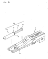
- Fig. 3 shows a syringe 20 to be mounted on such an automatic injecting apparatus 10.
- the automatic injecting apparatus 10 comprises a cylinder holder 11, a piston holder 12, and a motor inside (now shown), and the cylinder holder 11 fixes a syringe barrel 21 by holding a flange 22 and the piston holder 12 holds a piston flange 24.
- a piston 23 can be moved relative to the syringe barrel 21 by progressing or regressing the piston holder 12 by a motor, to effect injection (discharge of liquid from the syringe) or suction of liquid.
- Fig. 4 shows the syringe 20 mounted on the automatic injecting apparatus 10.
- a dismountable adaptor 13 functions as a cylinder holder for the syringe
- Fig. 6 shows the syringe 20 mounted on the automatic injecting apparatus 10.
- Fig. 8 provides detailed drawings of the adaptor 13 ((a) is a plan view, and (b) is a rear side view)).
- the syringe barrel 21 can be held by fitting the flange 22 of the syringe barrel 21 into a flange insertion groove 14 of the adaptor 13.
- the flange 22 is fitted into the flange groove 14 while directing a flange cut portion 25 vertically. Then, the flange is rotated by 90° to be fixed so that it is not disconnected.
- Fig. 7 (b) is a view showing the rotating process
- Fig.7 (c) is a view showing the use position.
- the flange thickness and the flange insertion groove width are so designed to give slight clearance between the flange and flange groove for enabling smooth mounting of the syringe barrel.
- the reason for this design is also that if the clearance is designed to zero completely, mounting may be sometimes impossible due to certain extent production error to be taken into consideration because the syringe barrel and the cylinder holder (including the adaptor) are usually formed of different materials. Consequently, slight backlash and play in mounted condition is inevitable. However, if there is an error in the mounting procedure, the syringe may sometimes be raised from the right position.
- the piston shall be pushed under condition in which the flange 22 is inclined relative to the flange insertion groove 14, as shown schematically in Fig. 9 , and the total pressure is concentrated only on a part of the flange, and resultantly, in the worst case, the flange may be occasionally broken particularly from the base part.
- the cut part of the flange is necessary also for prevention of syringe from rolling down when it is left on a plat surface such as on a table, in addition for such position determination.
- the syringe mentioned herein is the enlarged version (100 mL, 200 mL) of a syringe having a generally prevailing form composed of a syringe barrel and a piston. While a generally-used 50 to 60 mL syringe has a pressure resistance of about 3 kg/cm 2 , the syringe herein shown has an increased pressure resistance of about 20 kg/cm 2 to be used for injecting a contrast agent.
- a syringe for a contrast agent of no piston type there is also a syringe for a contrast agent of no piston type.
- a female screw provided on a member fixing a packing and a male screw on the tip of an axis on the injection apparatus side are connected and the axis is driven back and forth, to suck and inject a contrast agent.
- an automatic injecting apparatus should necessarily used also in sucking a chemical solution. Therefore, during diagnosis, since the automatic injecting apparatus is occupied, sucking of a chemical solution is impossible.
- a syringe of generally spread type as shown in Fig. 3 and the like has a merit that a chemical solution is filled in the syringe and is prepared previously as a chemical solution for the next inspection, even in diagnosis, since suction of a chemical solution is possible even manually and consequently an automatic injecting apparatus is not necessarily occupied. Further, as shown in Figs. 3 and 5 , there are also a merit that even syringes of different sizes can adopt the same injecting apparatus by using an adaptor, a merit that mounting to an apparatus is easy, and the like.
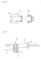
- FIG. 10 is an enlarged view of a cylinder holder portion of such an automatic injecting apparatus 110.
- This cylinder holder has two clamps 116, and before mounting of a syringe, the upper part of two clamps are open as shown in Fig. 10 .
- Fig. 11 (a) (upper left view in Fig. 11 )
- the syringe is fitted in two clamps 116 in open state while directing the flange cut surface vertically.
- Fig. 11 (b) upper right view in Fig. 19
- Fig. 11 (c) is a plan view of the fixed condition watched from the upper side (clamp part is drawn in sectional view).
- GB-A-2308302 discloses a sleeve to engage a syringe with textured surfaces
- US 3253 592 discloses a syringe with a barrel and a piston rod provided with a ribbed flange or finger strip and protusions on the end surface of the thumb rest.
- a purpose of the present invention is to prevent breakage of a syringe barrel in injecting liquid of high viscosity at high pressure.
- an objective of one aspect of the present invention is to provide an improved syringe barrel which is not easily broken.
- an objective of another aspect of the present invention is to provide a cylinder holder which causes no breakage of a syringe even if the syringe used is of usual type.
- an objective of another aspect of the present invention is to provide a cylinder holder which is used together with an improved syringe barrel and causes no breakage of a syringe.
- the above-mentioned syringe barrel can be combined with a syringe piston and used in a pre-filled syringe filled with a chemical solution.
- a contrast agent is exemplified.
- cylinder holder means one which can hold a syringe barrel by a groove, and when a syringe barrel is mounted on an adaptor before being set in an injecting apparatus, the term “cylinder holder” is construed to include such adaptor.
- the cylinder holder is usually incorporated in an automatic injecting apparatus, or integrated with an automatic injecting apparatus as one body.
- the apparatus as shown in Figs. 11 , 13 and 18 is typically exemplified.
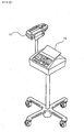
- This automatic injecting apparatus 10 can be used together with a controller 15 (operation mechanism) including a display, keyboard and the like as shown, for example, in Fig. 41.
- a controller 15 operation mechanism
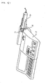
- a piston driving mechanism 16 with an operation mechanism 17 including a display, keyboard and the like.
- the syringe barrel 21 can be held by the cylinder holder 18.
- Fig. 38 shows one example of a syringe barrel of the present invention.
- the upper half of Fig. 38 (a) shows the section of a syringe barrel 310, and the lower half shows appearance thereof.
- Fig. 38 (b) is a side view of Fig. 38 (a) watched from B direction, namely, from the tip side of the syringe, and the front surface 313 of the flange is seen.
- Fig. 38 (c) is a side view of Fig. 38 (a) watched from C direction, namely, from the rear end side of the syringe, and the rear surface 314 of the flange 312 is seen.
- At least one of the front surface and the rear surface of a flange is roughened. Roughening of the front surface 313 is effective to prevent breakage of a syringe in injecting liquid (in discharging liquid from a syringe). On the other hand, roughening of the rear surface 314 is effective to prevent breakage of a syringe in sucking liquid (in introducing liquid into a syringe).
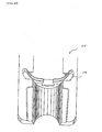
- Fig. 39 shows one example of a cylinder holder (adaptor) of the present invention
- Fig. 39 (a) is a top view
- Fig, 39 (b) is a side view watched from the rear side
- Fig. 39 (c) is an enlarged view of the X-X section of Fig. 39 (b).
- a flange is fitted in and fixed by a groove 321.
- At least one of a surface 322 contacting with the front surface of a flange and a surface 323 contacting with the rear surface of a flange is roughened.
- roughening of the surface contacting with the front surface of a flange is effective to prevent breakage of a syringe during injecting liquid (in discharging liquid from a syringe).
- roughening of the surface 323 contacting with the rear surface of a flange is effective to prevent breakage of a syringe in sucking liquid (in introducing liquid into a syringe).
- roughening of the surface 322 contacting with the front surface of a flange is effective to prevent breakage.
- the extent of roughening can be appropriately selected in view of materials of a syringe barrel and cylinder holder and mutual combination thereof, and the like.
- the roughening pattern may be, for example, random such as the surface of sand paper, or regular.
- convex-concave in the form of stripe may be used. In this case, it may be advantageous that approximately the above-mentioned roughening is formed along the direction crossing the stripe.
- regular roughening pattern when a syringe barrel is set on a cylinder holder, it is preferable that the pattern is so provided that friction resistance along vertical direction is large.
- whole of the front surface or the rear surface of a flange thereof may be roughened.
- only a part of it may be roughened.
- parts including a part contacting with a flange insertion groove are roughened.
- the raw material of the syringe barrel usual materials in circulation can be used, and from the standpoint of the strength of a flange, those made of resins such as, for example, a polypropylene resin and the like are preferable. Further, the raw material of a cylinder holder is not particularly restricted, and metals may also be used, in addition to resins such as polycarbonate, ABS and the like.
- a method of roughening a flange of a syringe barrel or a groove of a cylinder holder can be appropriately selected depending on materials. Specifically, the following methods and the like are listed.
- a mold for production of a cylinder holder holding a 100 mL syringe barrel In producing a mold for production of a cylinder holder holding a 100 mL syringe barrel, the mold surface of a part which forms the front surface of a cylinder holder was roughened by a sand blast method.
- a cylinder holder was produced according to injection molding using a polycarbonate resin.
- the surface roughness of the front surface of a flange insertion groove was No. 100 (Example 1), No. 200 (Example 2) or No. 300 (Example 3) in terms of count of sand paper (#100, #200 and #300, respectively).
- Cylinder holders were produced in the same manner as in Example 1 except that the surface of a mold in producing a cylinder holder was not roughened, and the same pressure-resistance test was conducted as in Example 1. The results are shown in Table 2.
- the front surface of a flange of a usual 100 mL syringe barrel was roughened using sand paper. Since this operation was conducted manually, the condition of the roughened surface was not completely random, and is believed to be No. 100 to No. 300 (#100 to #300).
- a cylinder holder made of a usual polycarbonate resin in which the groove surface had not been roughened was used in the pressure-resistance test to obtain approximately the same results as in Example 1.
- a syringe barrel can be provided which is not easily broken even in injecting a solution having high viscosity such as a contrast agent at higher pressure.
- a cylinder holder can be provided which does not cause breakage of a syringe even if it is a usual syringe.
Description
- The present invention relates to a syringe barrel suitable for injection at high injection pressure using a driving mechanism such as an automatic injector and the like; a cylinder holder used for a syringe driving mechanism such as an automatic injecting apparatus and the like; syringe piston; and piston holder.
- Syringes are used for injection of liquid in various fields typically including a medical field. Injection of a chemical solution having high viscosity such as a contrast agent for X ray CT imaging and a contrast agent for MRI (magnetic resonance imaging apparatus) requires high pressure, causes difficulty in manual handling, and makes intense jobs. Therefore, it is general to effect injection using a mechanical syringe driving mechanism such as an automatic injection apparatus and the like.
Fig. 3 shows asyringe 20 to be mounted on such an automatic injectingapparatus 10. The automatic injectingapparatus 10 comprises acylinder holder 11, apiston holder 12, and a motor inside (now shown), and thecylinder holder 11 fixes asyringe barrel 21 by holding aflange 22 and thepiston holder 12 holds apiston flange 24. Apiston 23 can be moved relative to thesyringe barrel 21 by progressing or regressing thepiston holder 12 by a motor, to effect injection (discharge of liquid from the syringe) or suction of liquid.Fig. 4 shows thesyringe 20 mounted on the automatic injectingapparatus 10. - Further, as shown in
Fig. 5 , when a syringe of smaller size is mounted on this automatic injecting apparatus, thesyringe barrel 21 is mounted on a dismountable adaptor 13 ( functions as a cylinder holder for the syringe) which is further mounted on the automatic injectingapparatus 10.Fig. 6 shows thesyringe 20 mounted on the automatic injectingapparatus 10. -
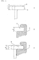
Fig. 8 provides detailed drawings of the adaptor 13 ((a) is a plan view, and (b) is a rear side view)). Thesyringe barrel 21 can be held by fitting theflange 22 of thesyringe barrel 21 into aflange insertion groove 14 of theadaptor 13. For the mounting, as shown inFig. 7 (a) , theflange 22 is fitted into theflange groove 14 while directing a flange cutportion 25 vertically. Then, the flange is rotated by 90° to be fixed so that it is not disconnected.Fig. 7 (b) is a view showing the rotating process, andFig.7 (c) is a view showing the use position. - In this constitution, the flange thickness and the flange insertion groove width are so designed to give slight clearance between the flange and flange groove for enabling smooth mounting of the syringe barrel. The reason for this design is also that if the clearance is designed to zero completely, mounting may be sometimes impossible due to certain extent production error to be taken into consideration because the syringe barrel and the cylinder holder (including the adaptor) are usually formed of different materials. Consequently, slight backlash and play in mounted condition is inevitable. However, if there is an error in the mounting procedure, the syringe may sometimes be raised from the right position. If injection of a contrast agent and chemical solution is conducted when fitting in such slight clearance is displaced, the piston shall be pushed under condition in which the
flange 22 is inclined relative to theflange insertion groove 14, as shown schematically inFig. 9 , and the total pressure is concentrated only on a part of the flange, and resultantly, in the worst case, the flange may be occasionally broken particularly from the base part. - The cut part of the flange is necessary also for prevention of syringe from rolling down when it is left on a plat surface such as on a table, in addition for such position determination.
- Further, the syringe mentioned herein is the enlarged version (100 mL, 200 mL) of a syringe having a generally prevailing form composed of a syringe barrel and a piston. While a generally-used 50 to 60 mL syringe has a pressure resistance of about 3 kg/cm2, the syringe herein shown has an increased pressure resistance of about 20 kg/cm2 to be used for injecting a contrast agent.
- On the other hand, there is also a syringe for a contrast agent of no piston type. In this type of syringe, a female screw provided on a member fixing a packing and a male screw on the tip of an axis on the injection apparatus side are connected and the axis is driven back and forth, to suck and inject a contrast agent. However, since such a syringe of no piston type is dedicated to an injector, an automatic injecting apparatus should necessarily used also in sucking a chemical solution. Therefore, during diagnosis, since the automatic injecting apparatus is occupied, sucking of a chemical solution is impossible.
- However, a syringe of generally spread type as shown in
Fig. 3 and the like has a merit that a chemical solution is filled in the syringe and is prepared previously as a chemical solution for the next inspection, even in diagnosis, since suction of a chemical solution is possible even manually and consequently an automatic injecting apparatus is not necessarily occupied. Further, as shown inFigs. 3 and5 , there are also a merit that even syringes of different sizes can adopt the same injecting apparatus by using an adaptor, a merit that mounting to an apparatus is easy, and the like. - As described above, there have been made various improvements in syringes for injecting a chemical solution such as a contrast agent and the like, however, when a chemical solution having high viscosity such as a contrast agent is injected, strong force is applied to a flange, consequently, the syringe may occasionally be broken if there are a small number of flange surfaces receiving pressure. If the flange is not rotated to given position and if injection is conducted, for example, in halfway condition as shown in
Fig. 7 (b) , crisis of breakage increases due to small area receiving pressure. - Further, in an apparatus for injection using a relatively large syringe having a size of about 200 mL, there has been recently contrived a mechanism for clamping in which a cylinder holder portion is mobilized and mounting of a flange can be effected simply and securely.
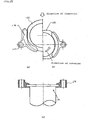
Fig. 10 is an enlarged view of a cylinder holder portion of such an automatic injectingapparatus 110. This cylinder holder has twoclamps 116, and before mounting of a syringe, the upper part of two clamps are open as shown inFig. 10 . Then, inFig. 11 (a) (upper left view inFig. 11 ), the syringe is fitted in twoclamps 116 in open state while directing the flange cut surface vertically. With progress of fitting, twoclamps 116 are pushed by the flange 122 and rotated around thefulcrum 117, leading to closed condition. By rotating the flange by 90° , the syringe is fixed while the flange cut surfaces 125 being situated at upper and lower positions as shown inFig 11 (b) (upper right view in Fig. 19).Fig. 11 (c) is a plan view of the fixed condition watched from the upper side (clamp part is drawn in sectional view). - However, even if such a clamp mechanism is used, when a syringe is fixed at a halfway position in a process from
Fig. 7(a) to Fig. 7 (b) , the pressure-receiving area of the flange decreases in injection and crisis of syringe breakage increases like the above-mentioned case. -
GB-A-2308302 -
US 3253 592 discloses a syringe with a barrel and a piston rod provided with a ribbed flange or finger strip and protusions on the end surface of the thumb rest. - A purpose of the present invention is to prevent breakage of a syringe barrel in injecting liquid of high viscosity at high pressure. For this purpose, an objective of one aspect of the present invention is to provide an improved syringe barrel which is not easily broken. Further, an objective of another aspect of the present invention is to provide a cylinder holder which causes no breakage of a syringe even if the syringe used is of usual type. Still further, an objective of another aspect of the present invention is to provide a cylinder holder which is used together with an improved syringe barrel and causes no breakage of a syringe.
- The above-mentioned syringe barrel can be combined with a syringe piston and used in a pre-filled syringe filled with a chemical solution. As this chemical solution, a contrast agent is exemplified.
- In the present invention, the term "cylinder holder" means one which can hold a syringe barrel by a groove, and when a syringe barrel is mounted on an adaptor before being set in an injecting apparatus, the term "cylinder holder" is construed to include such adaptor. The cylinder holder is usually incorporated in an automatic injecting apparatus, or integrated with an automatic injecting apparatus as one body.
- As an automatic injecting apparatus to which the present invention is applied, the apparatus as shown in
Figs. 11 ,13 and 18 is typically exemplified. Thisautomatic injecting apparatus 10 can be used together with a controller 15 (operation mechanism) including a display, keyboard and the like as shown, for example, in Fig. 41. Alternatively, as shown in Fig. 42, it can be applied to an automatic injecting apparatus obtained by integrating apiston driving mechanism 16 with anoperation mechanism 17 including a display, keyboard and the like. In this automatic injecting apparatus, thesyringe barrel 21 can be held by thecylinder holder 18. -
-
Fig. 1 is a view showing a syringe barrel mounted on a cylinder holder. -
Fig. 2 is an enlarged view.- (a) is a view showing fitting of a flange with a flange insertion groove of a cylinder holder.
- (b) is an enlarged view of a flange insertion groove of a cylinder holder.
- (c) is an enlarged view of a flange.
-
Fig. 3 is a view showing a syringe to be mounted on an automatic injecting apparatus. -
Fig. 4 is a view showing a syringe mounted on an automatic injecting apparatus. -
Fig. 5 is a view showing a syringe to be mounted on an automatic injecting apparatus by using an adaptor. -
Fig. 6 is a view showing a syringe mounted on an automatic injecting apparatus. -
Fig. 7 is a view illustrating holding and positioning of a syringe by a cylinder holder (adaptor) of an automatic injecting apparatus shown inFigs. 11 and13 . -
Fig. 8 is an enlarged view of an adaptor. -
Fig. 9 is a schematic view of a flange of a syringe barrel, which is raised from right position and displaced from a cylinder holder. -
Fig. 10 is a view showing a cylinder holder equipped with two movable clamps. -
Fig. 11 is a view illustrating holding and positioning of a syringe by a cylinder holder equipped with two movable clamps.- (a) is a view showing mounting of a syringe watched from the rear side of the syringe.
- (b) is a view showing a syringe after mounting watched from the rear side of the syringe.
- (c) is a top view showing a syringe after mounting.
-
Fig. 12 is a view showing one example of a syringe barrel. -
Fig. 13 is a view showing one example of a cylinder holder (adaptor). -
Fig. 14 is a view showing a syringe where a piston is drawn out. -
Fig. 15 is a view showing one example of an automatic injecting apparatus in which a piston driving mechanism and an operation mechanism are made separately as different bodies. -
Fig. 16 is a view showing one example of an automatic injecting apparatus in which a piston driving mechanism and an operation mechanism are integrated. - In this part, description will be made for a syringe barrel and/or a cylinder holder where roughened surface is made.
- Fig. 38 shows one example of a syringe barrel of the present invention. The upper half of Fig. 38 (a) shows the section of a
syringe barrel 310, and the lower half shows appearance thereof. Fig. 38 (b) is a side view of Fig. 38 (a) watched from B direction, namely, from the tip side of the syringe, and thefront surface 313 of the flange is seen. On the other hand, Fig. 38 (c) is a side view of Fig. 38 (a) watched from C direction, namely, from the rear end side of the syringe, and the rear surface 314 of theflange 312 is seen. - In the present invention, at least one of the front surface and the rear surface of a flange is roughened. Roughening of the
front surface 313 is effective to prevent breakage of a syringe in injecting liquid (in discharging liquid from a syringe). On the other hand, roughening of the rear surface 314 is effective to prevent breakage of a syringe in sucking liquid (in introducing liquid into a syringe). - In injecting liquid, large force is applied to a
syringe piston 311 pulled out as shown in Fig. 40, therefore, moment around fulcrum,flange 312 is large, resultantly, displacement tends to occur, and simultaneously, large force tends to be applied to the fulcrum. Consequently, breakage of a syringe barrel is more significant in the case of injection. Therefore, it is preferable to roughen at least the front surface of a flange. - Fig. 39 shows one example of a cylinder holder (adaptor) of the present invention, and Fig. 39 (a) is a top view, Fig, 39 (b) is a side view watched from the rear side, Fig. 39 (c) is an enlarged view of the X-X section of Fig. 39 (b). For holding a syringe barrel by this
cylinder holder 320, a flange is fitted in and fixed by agroove 321. In the cylinder holder of the present invention. At least one of asurface 322 contacting with the front surface of a flange and asurface 323 contacting with the rear surface of a flange is roughened. Like in roughening a flange surface of a syringe barrel, roughening of the surface contacting with the front surface of a flange is effective to prevent breakage of a syringe during injecting liquid (in discharging liquid from a syringe). On the other hand, roughening of thesurface 323 contacting with the rear surface of a flange is effective to prevent breakage of a syringe in sucking liquid (in introducing liquid into a syringe). Also in this case, roughening of thesurface 322 contacting with the front surface of a flange is effective to prevent breakage. - In the present invention, the extent of roughening can be appropriately selected in view of materials of a syringe barrel and cylinder holder and mutual combination thereof, and the like. For example, No. about 20 to 1500 (#20 to #1500), particularly No. about 50 to 800 (#50 to #800) is preferable, further, No. about 80 to 400 (#80 to #400) is preferable, in terms of the count of sand paper. The roughening pattern may be, for example, random such as the surface of sand paper, or regular. For example, convex-concave in the form of stripe may be used. In this case, it may be advantageous that approximately the above-mentioned roughening is formed along the direction crossing the stripe. In the case of regular roughening pattern, when a syringe barrel is set on a cylinder holder, it is preferable that the pattern is so provided that friction resistance along vertical direction is large.
- In the roughening, whole of the front surface or the rear surface of a flange thereof may be roughened. Alternative, only a part of it may be roughened. Particularly when set on a cylinder holder, it is preferable that parts including a part contacting with a flange insertion groove are roughened.
- As the raw material of the syringe barrel, usual materials in circulation can be used, and from the standpoint of the strength of a flange, those made of resins such as, for example, a polypropylene resin and the like are preferable. Further, the raw material of a cylinder holder is not particularly restricted, and metals may also be used, in addition to resins such as polycarbonate, ABS and the like.
- A method of roughening a flange of a syringe barrel or a groove of a cylinder holder can be appropriately selected depending on materials. Specifically, the following methods and the like are listed.
- (a) A method in which when a syringe barrel or a cylinder holder is molder, roughening is conducted simultaneously:
- In this method, a syringe barrel or a cylinder holder is molded by using a mold (usually, metal mold) having a roughened surface. At least, a portion of the surface of the mold which forms the surface of a flange surface or a groove surface required to be roughened has a roughened surface. Thus, a syringe barrel or cylinder holder made of a resin is produced in simple production with high productivity by injection molding and the like.
- (b) A method in which a flange surface or groove surface of a syringe barrel or cylinder holder manufactured is roughened mechanically:
- In this method, a flange surface or groove surface of a syringe barrel or cylinder holder which has been molded can be mechanically roughened by file rubbing, punching by a needle, sand blast and the like.
- (c) A method in which a roughened tape and the like are pasted on a flange surface or groove surface of a syringe barrel or cylinder holder manufactured:
- In this method, a member such as a tape and the like having a roughened surface is separately prepared, and is affixed integrally to a flange surface or groove surface of a syringe barrel or a cylinder holder by using an adhesive, or by heat fusion and the like.
- In using syringe barrels or cylinder holders as described above, it may be advantageous that at least one of them is roughened, and both of a syringe barrel and a cylinder holder may be roughened and combined for use.
- A syringe barrel or cylinder holder of the present invention can be used in uses such as injection of liquid and the like in various fields, and for example, it is preferably used for injecting a chemical solution for medical use for example, and particularly, it is preferably used for injecting a chemical solution having high viscosity such as a contrast agent requiring high pressure for the injection. For example, a syringe barrel or cylinder holder of the present invention can be used without breakage of a syringe, even in use for injecting a chemical solution requiring an injection pressure of 2 Mpa or more, further, 2.5 Mpa or more.
- Further, it is also preferable that a syringe barrel of the present invention is used as a pre-filled syringe which is previously filled with a chemical solution such as a contrast agent and the like.
- On the other hand, a syringe piston of the present invention is one in which the rear end surface of a piston rod is roughened. In a usually syringe, the rear end of a piston rod constitutes a
flange 331 as shown in Fig. 40, and in the present invention, therear end surface 330 of thisflange 331 is roughened. - A piston holder of the present invention is one in which a press surface contacting with the rear end surface of a syringe piston rod is roughened, and for example, in an automatic injecting apparatus of
Fig. 11 , apress surface 12 for pressing therear end surface 330 of a piston rod is roughened. Usually, a piston holder has a press surface, and a clamp mechanism for holding a flange of a piston, and various embodiments are possible. - Raw materials, extent of roughening (roughness, area), roughening method, rough surface forming method and the like can be set according to the above-mentioned syringe barrel. Likewise, those of a piston holder can be set according to the above-mentioned cylinder holder.
- These syringe piston and piston holder are also preferably used particularly for injecting chemical solution having high viscosity such as a contrast agent requiring high pressure, and use of a pre-filled syringe previously-filled with a chemical solution such as a contrast agent and the like is also preferable.
- The following examples illustrate the present invention further in detail below.
- In producing a mold for production of a cylinder holder holding a 100 mL syringe barrel, the mold surface of a part which forms the front surface of a cylinder holder was roughened by a sand blast method. By this mold, a cylinder holder was produced according to injection molding using a polycarbonate resin. The surface roughness of the front surface of a flange insertion groove was No. 100 (Example 1), No. 200 (Example 2) or No. 300 (Example 3) in terms of count of sand paper (#100, #200 and #300, respectively).
- By using this cylinder holder, a 23 G butterfly needle was mounted on a syringe (internal diameter: 32 mm) of 100 mL capacity using a usual polypropylene syringe barrel in which the surface of a flange had not been roughened, and a pressure-resistance test was conducted using water as injection liquid. The results are shown in Table 1. In this test, breakage of the syringe and displacement of the flange such as raising from the right position did not occur even if injection was conducted at a high injection speed of 6 mL/sec and consequently the pressure increased to 28 kg/cm2.
Table 1 Injection rate (mL/sec) Pressure gage indication (MPa) Remarks Example 1 6 2. 83 Three 6 2. 88 continuous 6 2. 86 injection Example 2 6 2. 86 Three 6 2. 88 continuous 6 2. 83 injection Example 3 6 2. 87 Three 6 2. 79 continuous 6 2. 83 injection - Cylinder holders were produced in the same manner as in Example 1 except that the surface of a mold in producing a cylinder holder was not roughened, and the same pressure-resistance test was conducted as in Example 1. The results are shown in Table 2.
Table 2 Injection rate (mL/sec) Maximum pressure (MPa) Remarks Comparative Example 1 3. 5 1. 80 Injection rate is low Comparative Example 2 4. 0 2. 14 Raised and deviated from holder Comparative Example 3 4. 0 2. 06 Raised and deviated from holder Comparative Example 4 4. 0 2. 17 Syringe barrel was broken Comparative Example 5 4. 0 2. 25 Syringe barrel was broken Comparative Example 6 4. 6 2. 33 Syringe barrel was broken Comparative Example 7 4. 0 2. 33 Syringe barrel was broken - The front surface of a flange of a usual 100 mL syringe barrel was roughened using sand paper. Since this operation was conducted manually, the condition of the roughened surface was not completely random, and is believed to be No. 100 to No. 300 (#100 to #300). A cylinder holder made of a usual polycarbonate resin in which the groove surface had not been roughened was used in the pressure-resistance test to obtain approximately the same results as in Example 1.
- As described above, according to the present invention, including all aspects of the invention, a syringe barrel can be provided which is not easily broken even in injecting a solution having high viscosity such as a contrast agent at higher pressure.
- Further, according to the present invention, a cylinder holder can be provided which does not cause breakage of a syringe even if it is a usual syringe.
Claims (13)
- A syringe barrel (310), comprising a flange (312) having a front surface (313) and a rear surface (314), characterized in that at least one of the front surface and the rear surface of the flange is roughened.
- The syringe barrel of claim 1 wherein the cross section of the roughened surface has a roughness of about No. 20 to 1500 as expressed in terms of counts of sand paper.
- A syringe barrel according to claim 1 for use in an injection apparatus (10), said syringe barrel adapted to be mounted on a cylinder holder (11, 320) that comprises a flange insertion groove (321), wherein said flange is adapted to be held by said flange insertion groove so as to fix the syringe barrel.
- The syringe barrel according to Claim 1, wherein the front surface of the flange is roughened.
- A syringe barrel according to claim 4 for use in an injection apparatus, said syringe barrel adapted to be mounted on a cylinder holder that comprises a flange insertion groove, wherein said flange is adapted to be held by said flange insertion groove so as to fix the syringe barrel.
- A cylinder holder characterized in that it comprises a flange insertion groove for holding a syringe barrel that comprises a flange having a front surface and a rear surface; said insertion groove having a front surface and a rear surface, at least one of the surfaces of the flange insertion groove being roughened, said roughened surface adapted to be contacted with the front surface or the rear surface of the flange.
- The cylinder holder according to Claim 6, wherein the surface to be contacted with the front surface of the flange of the syringe barrel is roughened.
- The cylinder holder according to claim 7, wherein the cross section of the roughened surface has a roughness of about No. 20 to 1500 ax expressed in terms of count of sand paper.
- A syringe piston, characterized in that it comprises a syringe piston rod having a rear end surface that is roughened.
- The syringe piston according to claim 9, wherein the cross section of the roughened surface has a roughness of about No. 20 to 1500 as expressed in terms of count of sand paper.
- A piston holder, characterized in that it comprises a roughened press surface adapted to contact the rear end surface of a syringe piston rod.
- The piston holder according to claim 11, wherein the cross section of the roughened surface has a roughness of about No. 20 to 1500 as expressed in terms of count of sand paper.
- A pre-filled syringe, characterized in that it comprises:a syringe comprising a syringe barrel of any of Claims 1 to 5 or a syringe piston of Claim 8; anda chemical solution filled in the syringe.
Applications Claiming Priority (9)
| Application Number | Priority Date | Filing Date | Title |
|---|---|---|---|
| JP2000033520A JP4593714B2 (en) | 2000-02-10 | 2000-02-10 | Syringe outer cylinder, syringe holder, syringe piston and piston holder |
| JP2000033520 | 2000-02-10 | ||
| JP2000037176A JP2001224685A (en) | 2000-02-10 | 2000-02-15 | Flange part reinforced syringe outer cylinder |
| JP2000037176 | 2000-02-15 | ||
| JP2000198358 | 2000-06-30 | ||
| JP2000198358A JP4567149B2 (en) | 2000-02-10 | 2000-06-30 | Chemical injection system |
| JP2001026782 | 2001-02-02 | ||
| JP2001026782A JP4751514B2 (en) | 2000-02-10 | 2001-02-02 | Syringe cylinder and cylinder holder |
| EP01400344A EP1123712B9 (en) | 2000-02-10 | 2001-02-09 | Syringe barrel and cylinder holder |
Related Parent Applications (1)
| Application Number | Title | Priority Date | Filing Date |
|---|---|---|---|
| EP01400344A Division EP1123712B9 (en) | 2000-02-10 | 2001-02-09 | Syringe barrel and cylinder holder |
Publications (3)
| Publication Number | Publication Date |
|---|---|
| EP1449552A2 EP1449552A2 (en) | 2004-08-25 |
| EP1449552A3 EP1449552A3 (en) | 2004-12-29 |
| EP1449552B1 true EP1449552B1 (en) | 2010-01-20 |
Family
ID=27481023
Family Applications (7)
| Application Number | Title | Priority Date | Filing Date |
|---|---|---|---|
| EP08103395A Expired - Lifetime EP1938853B1 (en) | 2000-02-10 | 2001-02-09 | Syringe barrel and cylinder holder |
| EP04076550A Expired - Lifetime EP1454645B1 (en) | 2000-02-10 | 2001-02-09 | Syringe barrel and cylinder holder |
| EP04076413A Expired - Lifetime EP1447106B1 (en) | 2000-02-10 | 2001-02-09 | Syringe barrel and cylinder holder |
| EP04076575A Expired - Lifetime EP1449552B1 (en) | 2000-02-10 | 2001-02-09 | Syringe barrel and cylinder holder |
| EP08103393A Withdrawn EP1944047A3 (en) | 2000-02-10 | 2001-02-09 | Syringe barrel and cylinder holder |
| EP04076459A Expired - Lifetime EP1466640B1 (en) | 2000-02-10 | 2001-02-09 | Syringe barrel and cylinder holder |
| EP01400344A Expired - Lifetime EP1123712B9 (en) | 2000-02-10 | 2001-02-09 | Syringe barrel and cylinder holder |
Family Applications Before (3)
| Application Number | Title | Priority Date | Filing Date |
|---|---|---|---|
| EP08103395A Expired - Lifetime EP1938853B1 (en) | 2000-02-10 | 2001-02-09 | Syringe barrel and cylinder holder |
| EP04076550A Expired - Lifetime EP1454645B1 (en) | 2000-02-10 | 2001-02-09 | Syringe barrel and cylinder holder |
| EP04076413A Expired - Lifetime EP1447106B1 (en) | 2000-02-10 | 2001-02-09 | Syringe barrel and cylinder holder |
Family Applications After (3)
| Application Number | Title | Priority Date | Filing Date |
|---|---|---|---|
| EP08103393A Withdrawn EP1944047A3 (en) | 2000-02-10 | 2001-02-09 | Syringe barrel and cylinder holder |
| EP04076459A Expired - Lifetime EP1466640B1 (en) | 2000-02-10 | 2001-02-09 | Syringe barrel and cylinder holder |
| EP01400344A Expired - Lifetime EP1123712B9 (en) | 2000-02-10 | 2001-02-09 | Syringe barrel and cylinder holder |
Country Status (6)
| Country | Link |
|---|---|
| US (8) | US6676635B2 (en) |
| EP (7) | EP1938853B1 (en) |
| JP (4) | JP4593714B2 (en) |
| KR (5) | KR100830062B1 (en) |
| CN (4) | CN1827181B (en) |
| DE (5) | DE60126167T2 (en) |
Families Citing this family (74)
| Publication number | Priority date | Publication date | Assignee | Title |
|---|---|---|---|---|
| JP4593714B2 (en) * | 2000-02-10 | 2010-12-08 | 株式会社根本杏林堂 | Syringe outer cylinder, syringe holder, syringe piston and piston holder |
| US6652489B2 (en) | 2000-02-07 | 2003-11-25 | Medrad, Inc. | Front-loading medical injector and syringes, syringe interfaces, syringe adapters and syringe plungers for use therewith |
| JP4256677B2 (en) * | 2001-01-18 | 2009-04-22 | メドラッド インコーポレーテッド | Syringe interface and adapter used for medical injectors |
| JP4794767B2 (en) * | 2001-08-01 | 2011-10-19 | 株式会社根本杏林堂 | Cylinder holder, chemical solution injection system, and syringe outer cylinder used therefor |
| JP4044779B2 (en) * | 2002-04-02 | 2008-02-06 | 株式会社根本杏林堂 | Chemical injection system |
| US6929619B2 (en) * | 2002-08-02 | 2005-08-16 | Liebel-Flarshiem Company | Injector |
| NO20023724D0 (en) * | 2002-08-07 | 2002-08-07 | Amersham Health As | Adapter |
| JP4620929B2 (en) | 2002-09-26 | 2011-01-26 | 株式会社根本杏林堂 | Chemical injection device |
| JP4594582B2 (en) * | 2002-12-10 | 2010-12-08 | 株式会社根本杏林堂 | Chemical injection device |
| JP4286019B2 (en) * | 2003-02-04 | 2009-06-24 | 株式会社根本杏林堂 | Chemical injection system |
| JP4731795B2 (en) | 2003-02-18 | 2011-07-27 | 株式会社根本杏林堂 | Chemical injection device |
| JP4490642B2 (en) | 2003-04-01 | 2010-06-30 | 株式会社根本杏林堂 | Chemical injection device |
| JP2004313579A (en) * | 2003-04-18 | 2004-11-11 | Nemoto Kyorindo:Kk | Medical fluid filling device |
| JP4338447B2 (en) * | 2003-06-06 | 2009-10-07 | 株式会社根本杏林堂 | Chemical injection system |
| JP2005000203A (en) | 2003-06-09 | 2005-01-06 | Nemoto Kyorindo:Kk | Liquid medication injection system |
| US7500961B2 (en) | 2003-07-07 | 2009-03-10 | Nemoto Kyorindo Co., Ltd. | Chemical liquid injection system detecting mount and dismount of chemical liquid syringe to and from chemical liquid injector |
| CN100536943C (en) | 2003-07-18 | 2009-09-09 | 株式会社根本杏林堂 | Medicine infuser for displaying image of entered infusion condition |
| JP2005131007A (en) * | 2003-10-29 | 2005-05-26 | Nemoto Kyorindo:Kk | Medical fluid injection system |
| JP4786344B2 (en) * | 2003-10-29 | 2011-10-05 | 株式会社根本杏林堂 | Chemical injection device |
| US20070282277A1 (en) * | 2003-12-09 | 2007-12-06 | George Gallagher | Syringe Driver Housing |
| US20080287785A1 (en) * | 2004-04-05 | 2008-11-20 | Yasufumi Saitoh | Chemical Liquid Injection System |
| JP2006014804A (en) * | 2004-06-30 | 2006-01-19 | Nemoto Kyorindo:Kk | Member holding mechanism |
| US20080161634A1 (en) * | 2004-11-11 | 2008-07-03 | Toru Nemoto | Tube Connection Apparatus |
| WO2006057089A1 (en) | 2004-11-26 | 2006-06-01 | Nemoto Kyorindo Co., Ltd | Medical fluid injection system |
| JP4833984B2 (en) * | 2005-08-29 | 2011-12-07 | 株式会社根本杏林堂 | Chemical injection system |
| DE102005042076B4 (en) | 2005-08-31 | 2007-06-06 | Bayer Schering Pharma Ag | Burst protection device for a syringe |
| JP4512021B2 (en) * | 2005-10-05 | 2010-07-28 | 三菱重工業株式会社 | Dilution operation jig for radioactive sample and transfer method |
| JP4890052B2 (en) * | 2006-03-02 | 2012-03-07 | 株式会社根本杏林堂 | Chemical injection device |
| CN101466614B (en) * | 2006-06-13 | 2013-05-01 | 诺信公司 | Liquid dispensing syringe |
| US8454560B2 (en) | 2006-12-05 | 2013-06-04 | Mallinckrodt Llc | Syringe mount for a medical fluid injector |
| JP2008194317A (en) * | 2007-02-14 | 2008-08-28 | Daikyo Seiko Ltd | Syringe barrel and syringe |
| USD588693S1 (en) | 2007-06-12 | 2009-03-17 | Nordson Corporation | Liquid dispensing syringe |
| USD738495S1 (en) | 2013-08-23 | 2015-09-08 | Nordson Corporation | Piston for a liquid dispensing syringe |
| JP2009283685A (en) * | 2008-05-22 | 2009-12-03 | Panasonic Corp | Semiconductor device, and its method for manufacturing |
| US8708975B2 (en) * | 2009-03-06 | 2014-04-29 | Sanofi-Aventis Deutschland Gmbh | Syringe, auto-injector device and set of auto-injector devices and syringes |
| JP5436897B2 (en) * | 2009-03-18 | 2014-03-05 | 株式会社根本杏林堂 | Syringe lock mechanism |
| CN102427838B (en) * | 2009-03-18 | 2015-09-09 | 株式会社根本杏林堂 | Chemical liquid infuser |
| JP5518841B2 (en) | 2009-03-18 | 2014-06-11 | 株式会社根本杏林堂 | Syringe adapter |
| JP5346231B2 (en) * | 2009-03-19 | 2013-11-20 | 株式会社根本杏林堂 | Syringe holder |
| US8287494B2 (en) * | 2009-03-23 | 2012-10-16 | Colin Ma | Intravitreal injection devices and methods of injecting a substance into the vitreous chamber of the eye |
| US10383995B2 (en) | 2009-03-27 | 2019-08-20 | Nemoto Kyorindo Co., Ltd. | Syringe holding structure |
| EP2243505B1 (en) * | 2009-04-23 | 2018-02-14 | Bayer Healthcare LLC | Syringe assemblies, methods of forming syringe assemblies |
| IN2012DN00344A (en) | 2009-07-10 | 2015-05-08 | Becton Dickinson Co | |
| EP2962770B1 (en) | 2009-07-24 | 2017-03-22 | Bayer Healthcare LLC | Multi-fluid medical injector system |
| JP5728634B2 (en) * | 2010-04-06 | 2015-06-03 | 株式会社テクトロン | Syringe for syringe pump and syringe mounting member |
| FR2961403B1 (en) * | 2010-06-17 | 2013-06-14 | Rexam Healthcare La Verpillier | SET OF A SYRINGE AND A SAFETY DEVICE |
| DE102011009908A1 (en) * | 2011-01-31 | 2012-08-02 | Fresenius Medical Care Deutschland Gmbh | Clamping holder for a syringe of a dosing device, dosing device and blood treatment device |
| DE102011015112A1 (en) * | 2011-03-21 | 2012-09-27 | Vetter Pharma-Fertigung GmbH & Co. KG | Container, holding device, holding system and injection aid |
| US9174003B2 (en) | 2012-09-28 | 2015-11-03 | Bayer Medical Care Inc. | Quick release plunger |
| US20140092376A1 (en) * | 2012-10-01 | 2014-04-03 | Momentive Performance Materials, Inc. | Container and method for in-line analysis of protein compositions |
| US9138772B2 (en) | 2012-10-31 | 2015-09-22 | Nordson Corporation | Dispensing assembly and method using snap engagement of a mixer and a cartridge |
| WO2014168216A1 (en) * | 2013-04-11 | 2014-10-16 | 株式会社根本杏林堂 | Data processing device, medical testing system, and computer program |
| JP6338190B2 (en) * | 2013-04-11 | 2018-06-06 | 株式会社根本杏林堂 | Chemical injection device |
| CN106102806B (en) | 2014-03-19 | 2019-12-17 | 拜耳医药保健有限公司 | System for coupling a syringe to an injector |
| CN105198800B (en) * | 2014-06-25 | 2018-02-16 | 江苏扬农化工集团有限公司 | A kind of preparation method of the picoline of 2,3 dichloro of pesticide intermediate 5 |
| NO2689315T3 (en) | 2014-10-28 | 2018-04-14 | ||
| US9199033B1 (en) | 2014-10-28 | 2015-12-01 | Bayer Healthcare Llc | Self-orienting syringe and syringe interface |
| US11129934B2 (en) | 2014-10-28 | 2021-09-28 | Bayer Healthcare Llc | Self-orienting pressure jacket and pressure jacket-to-injector interface |
| RU2709546C2 (en) | 2014-10-28 | 2019-12-18 | БАЙЕР ХелсКер ЛЛСи | Self-oriented high-pressure casing and mechanism for high pressure casing and injector connection |
| CN107427360A (en) * | 2015-04-17 | 2017-12-01 | 兴和株式会社 | Intraocular lens inserting tool |
| US10835674B2 (en) | 2015-11-13 | 2020-11-17 | Bayer Healthcare Llc | Nested syringe assembly |
| CN106215284B (en) * | 2016-07-07 | 2022-03-11 | 邓源基 | Clutch mechanism of pen type injector |
| US10821053B2 (en) | 2016-10-07 | 2020-11-03 | Becton, Dickinson And Company | Syringe with connector |
| US10537683B2 (en) | 2016-11-03 | 2020-01-21 | Johnson & Johnson Surgical Vision, Inc. | Syringe finger grip |
| US20180169326A1 (en) * | 2016-12-20 | 2018-06-21 | Liebel-Flarsheim Company Llc | Tapered front-load power injector syringe |
| CN111032125A (en) | 2017-07-21 | 2020-04-17 | 贝克顿迪金森法国公司 | Auxiliary injection device for injecting a component contained in a medical container with a low force |
| US11654252B2 (en) | 2017-09-29 | 2023-05-23 | West Pharmaceutical Services, Inc. | Housing with syringe holding feature |
| EP3717044A4 (en) * | 2017-12-01 | 2021-08-25 | Merck Sharp&dohme Pharmaceutical Industrial and Commercial Societe Anonyme | Syringe having at least one radially-outwardly extending panel |
| US11083847B2 (en) | 2018-01-26 | 2021-08-10 | Becton, Dickinson And Company | Flush syringe with flip cap |
| US11191893B2 (en) | 2018-01-31 | 2021-12-07 | Bayer Healthcare Llc | System and method for syringe engagement with injector |
| CN110215572B (en) * | 2019-06-20 | 2021-07-23 | 纳智医疗设备(徐州)有限公司 | Syringe positioning mechanism for syringe pump |
| CN110587984A (en) * | 2019-09-23 | 2019-12-20 | 天津勒燕封胥科技有限公司 | Novel micro-injection pump |
| CN110776827A (en) * | 2019-10-31 | 2020-02-11 | 张继 | Metal preservative |
| CN113476681B (en) * | 2021-08-13 | 2022-09-09 | 深圳瑞格泰科医疗科技有限公司 | DSA high-pressure injector and needle cylinder dismounting mechanism thereof |
Family Cites Families (83)
| Publication number | Priority date | Publication date | Assignee | Title |
|---|---|---|---|---|
| US120212A (en) * | 1871-10-24 | Improvement in carpenters planes | ||
| US21823A (en) * | 1858-10-19 | Rtjfus dawes | ||
| US14996A (en) * | 1856-06-03 | Feeding apparatus for gas-retorts | ||
| GB190924783A (en) * | 1909-10-28 | 1910-10-13 | Henry Solomon Wellcome | Improved Dental Syringe. |
| GB191024783A (en) | 1910-10-25 | 1911-10-25 | Alfred Julius Boult | Improvements in or relating to Nailing or Tacking Apparatus for Machines Employed in the Manufacture of Boots and Shoes. |
| US2627270A (en) | 1946-02-09 | 1953-02-03 | Antonina S Glass | Self-propelled automatic syringe |
| US2695612A (en) * | 1951-09-27 | 1954-11-30 | Abbott Lab | Hypodermic syringe |
| CH366634A (en) * | 1959-01-28 | 1963-01-15 | Hennings Werner | Injection ampoule with handle |
| US3226099A (en) * | 1962-05-07 | 1965-12-28 | Vendo Co | Apparatus for preparing and discharging water having controlled amounts of carbonation |
| US3253592A (en) | 1962-06-08 | 1966-05-31 | Baxter Don Inc | Plastic syringe |
| US3316909A (en) * | 1963-12-30 | 1967-05-02 | Pharmaseal Lab | Hypodermic syringe operable by one hand |
| US3438549A (en) | 1967-09-29 | 1969-04-15 | Baxter Laboratories Inc | Pre-filled syringe |
| US3556099A (en) * | 1968-05-27 | 1971-01-19 | Johnson & Johnson | Hypodermic syringe assembly |
| DE7036471U (en) * | 1970-10-02 | 1971-01-14 | Chemie Gruessenthal Gmbh | FINGERREST FOR INJECTION CARTRIDGES. |
| US4030498A (en) | 1974-10-25 | 1977-06-21 | Baxter Travenol Laboratories, Inc. | Syringe |
| US4006736A (en) | 1974-11-27 | 1977-02-08 | Medrad, Inc. | Angiographic injector |
| US3990446A (en) | 1975-02-18 | 1976-11-09 | Jewel Dean Randolph Taylor | Hypodermic syringe for stabilized aspiration by one hand |
| US4253501A (en) * | 1979-11-09 | 1981-03-03 | Ims Limited | Transfer system |
| US4424720A (en) * | 1980-12-15 | 1984-01-10 | Ivac Corporation | Mechanism for screw drive and syringe plunger engagement/disengagement |
| US4516969A (en) * | 1983-04-14 | 1985-05-14 | Medtech Plastics, Inc. | Control syringe |
| US4540405A (en) | 1983-07-12 | 1985-09-10 | Cilco, Inc. | Disposable syringe sleeve |
| DE3587540T3 (en) * | 1984-06-06 | 1998-01-22 | Medrad Inc | Angiography syringe for use with an angiography injector. |
| JPS6128627A (en) | 1984-07-19 | 1986-02-08 | Masaaki Uchida | Energy-saving construction for deep foundation |
| US4838857A (en) | 1985-05-29 | 1989-06-13 | Becton, Dickinson And Company | Medical infusion device |
| EP0208975A3 (en) | 1985-07-04 | 1987-05-20 | Antonio Gomez Gomez | Syringe for producing vacuum-controlled suction |
| US4718463A (en) * | 1985-12-20 | 1988-01-12 | Mallinckrodt, Inc. | Method of producing prefilled sterile plastic syringes |
| US4804368A (en) | 1986-12-05 | 1989-02-14 | C. R. Bard, Inc. | Battery operated miniature syringe infusion pump and improved halfnut therefor |
| JPS63182742U (en) * | 1987-05-15 | 1988-11-25 | ||
| EP0335947A4 (en) | 1987-10-14 | 1990-09-05 | John Henry Adam Butler | Single use syringe |
| US5059185A (en) * | 1988-03-01 | 1991-10-22 | Ryan Medical, Inc. | Safety needled medical devices |
| GB8903581D0 (en) * | 1989-02-16 | 1989-04-05 | Metal Box Plc | Injection moulding |
| US5188599A (en) | 1989-07-11 | 1993-02-23 | Med-Design, Inc. | Retractable needle system |
| US5407431A (en) * | 1989-07-11 | 1995-04-18 | Med-Design Inc. | Intravenous catheter insertion device with retractable needle |
| US5022563A (en) * | 1990-01-10 | 1991-06-11 | Electron Fusion Devices, Inc. | Dispenser-gun assembly for viscous fluids and dispenser therefor |
| DE9105980U1 (en) * | 1991-05-15 | 1991-07-04 | B. Braun Melsungen Ag, 3508 Melsungen, De | |
| DE69212069T2 (en) * | 1991-05-23 | 1997-02-20 | Ivac Corp | Drive system for the piston rod of a syringe |
| US5300031A (en) * | 1991-06-07 | 1994-04-05 | Liebel-Flarsheim Company | Apparatus for injecting fluid into animals and disposable front loadable syringe therefor |
| JPH0636827B2 (en) * | 1991-08-09 | 1994-05-18 | アトム株式会社 | Infusion device |
| AT397467B (en) | 1991-10-22 | 1994-04-25 | Wimmer Erwin | DISPOSABLE SYRINGE |
| US5593391A (en) | 1992-02-13 | 1997-01-14 | Stanners; Sydney D. | Ampule safety syringe |
| US5226897A (en) | 1992-02-28 | 1993-07-13 | Professional Medical Products, Inc. | Manually driven piston syringe with frangibly mounted tube adapter |
| US5322511A (en) * | 1992-04-21 | 1994-06-21 | Sterling Winthrop Inc. | Portable hand-held power injector |
| US5306157A (en) * | 1992-06-15 | 1994-04-26 | Francisco Thomas E | Adjustable duplex receptacle |
| US5383858B1 (en) * | 1992-08-17 | 1996-10-29 | Medrad Inc | Front-loading medical injector and syringe for use therewith |
| GB9309151D0 (en) * | 1993-05-04 | 1993-06-16 | Zeneca Ltd | Syringes and syringe pumps |
| US5429611A (en) * | 1993-06-10 | 1995-07-04 | Rait; Joseph M. | Syringe with automatically actuated shield |
| US5306147A (en) * | 1993-06-28 | 1994-04-26 | Dragan William B | Dental syringe and cartridge therefor |
| DE59409006D1 (en) * | 1994-01-28 | 2000-01-20 | Mallinckrodt Medical Gmbh | Conversion kit for an injection machine for use with syringes with different diameters |
| US5624260A (en) * | 1994-02-28 | 1997-04-29 | Minnesota Mining And Manufacturing Company | Delivery system for aqueous paste dental materials |
| US5535746A (en) * | 1994-03-29 | 1996-07-16 | Sterling Winthrop Inc. | Prefilled syringe for use with power injector |
| JP2828898B2 (en) | 1994-05-17 | 1998-11-25 | 株式会社三五 | Exhaust pipe joint structure and manufacturing method |
| US5554132A (en) * | 1995-03-30 | 1996-09-10 | Abbott Laboratories | Hand grip for use with syringe |
| US5667495A (en) | 1995-04-21 | 1997-09-16 | Becton Dickinson France S.A. | Backstop device for a syringe |
| US5722956A (en) * | 1995-08-24 | 1998-03-03 | The General Hospital Corporation | Multi-dose syringe driver |
| US5779675A (en) * | 1995-08-25 | 1998-07-14 | Medrad, Inc. | Front load pressure jacket system with syringe holder |
| JP3429922B2 (en) * | 1995-10-30 | 2003-07-28 | スーガン株式会社 | Auxiliary device for syringe fixation |
| JPH09125600A (en) | 1995-11-01 | 1997-05-13 | Dai Ichi High Frequency Co Ltd | Steel pipe with flange and its manufacture |
| GB2308302B (en) * | 1995-12-20 | 1997-11-12 | John Gill | Syringe |
| US5873499A (en) * | 1996-08-14 | 1999-02-23 | Scientific Resources, Inc. | Pressure breakaway dispensing gun |
| US5873861A (en) * | 1996-11-12 | 1999-02-23 | Medrad, Inc. | Plunger systems |
| US5947935A (en) * | 1996-11-12 | 1999-09-07 | Medrad, Inc. | Syringes, syringe plungers and injector systems |
| EP0951306B1 (en) * | 1996-11-12 | 2005-07-20 | Medrad Inc. | Prefillable syringes and injectors for use therewith |
| US5944694A (en) * | 1996-11-12 | 1999-08-31 | Medrad, Inc. | Prefillable syringes and injectors for use therewith |
| JP4438970B2 (en) * | 1996-11-13 | 2010-03-24 | ブラッコ インターナショナル ビーヴィ | Pre-filled syringe |
| US5833668A (en) * | 1996-11-21 | 1998-11-10 | Aguilar; David G. | Hypodermic syringe |
| DE19723851C1 (en) | 1997-06-06 | 1998-10-08 | Schott Glas | Handle bar for prefilled disposable syringes |
| US6569127B1 (en) * | 1997-07-18 | 2003-05-27 | Liebel-Flarsheim Company | Adapter and syringe for front-loading medical fluid injector |
| US5947929A (en) | 1997-08-22 | 1999-09-07 | Coeur Laboratories, Inc. | Front-load angiographic injector system, angiographic syringe and plunger for angiographic syringe |
| US6117112A (en) * | 1997-11-18 | 2000-09-12 | Mahurkar; Sakharam D. | Single-use safety syringe |
| DE69836896T2 (en) | 1997-11-26 | 2007-11-08 | Liebel-Flarsheim Co., Cincinnati | Front loading syringe pump and method of loading with a flanged syringe |
| JPH11178923A (en) * | 1997-12-22 | 1999-07-06 | Shiseido Co Ltd | Flange for syringe |
| US5925032A (en) * | 1998-02-17 | 1999-07-20 | Alcon Laboratories, Inc. | Syringe cannula holder |
| US6256841B1 (en) | 1998-12-31 | 2001-07-10 | Otis Elevator Company | Wedge clamp type termination for elevator tension member |
| US6679864B2 (en) | 1998-04-17 | 2004-01-20 | Becton Dickinson And Company | Safety shield system for prefilled syringes |
| US6054012A (en) * | 1998-06-29 | 2000-04-25 | Intersil Corporation | Decapsulating method and apparatus for integrated circuit packages |
| DE19929325A1 (en) | 1999-06-26 | 2001-01-18 | Vetter & Co Apotheker | Syringe for medical purposes |
| JP4838468B2 (en) | 1999-07-30 | 2011-12-14 | メドラッド インコーポレーテッド | Injector system and syringe adapter used in the injector system |
| US6368308B1 (en) | 1999-09-17 | 2002-04-09 | Michael E. Nerney | Syringe having forward-mounted plunger control |
| US6958053B1 (en) | 1999-11-24 | 2005-10-25 | Medrad, Inc. | Injector providing drive member advancement and engagement with syringe plunger, and method of connecting a syringe to an injector |
| US6457606B1 (en) * | 2000-01-27 | 2002-10-01 | Bright Solutions, Inc. | Method and device for introducing fluid material into a climate control system |
| JP4593714B2 (en) | 2000-02-10 | 2010-12-08 | 株式会社根本杏林堂 | Syringe outer cylinder, syringe holder, syringe piston and piston holder |
| JP4256677B2 (en) | 2001-01-18 | 2009-04-22 | メドラッド インコーポレーテッド | Syringe interface and adapter used for medical injectors |
| JP4794767B2 (en) | 2001-08-01 | 2011-10-19 | 株式会社根本杏林堂 | Cylinder holder, chemical solution injection system, and syringe outer cylinder used therefor |
-
2000
- 2000-02-10 JP JP2000033520A patent/JP4593714B2/en not_active Expired - Lifetime
- 2000-02-15 JP JP2000037176A patent/JP2001224685A/en not_active Withdrawn
- 2000-06-30 JP JP2000198358A patent/JP4567149B2/en not_active Expired - Lifetime
-
2001
- 2001-02-02 JP JP2001026782A patent/JP4751514B2/en not_active Expired - Lifetime
- 2001-02-09 EP EP08103395A patent/EP1938853B1/en not_active Expired - Lifetime
- 2001-02-09 DE DE60126167T patent/DE60126167T2/en not_active Expired - Lifetime
- 2001-02-09 DE DE60134582T patent/DE60134582D1/en not_active Expired - Lifetime
- 2001-02-09 CN CN200610001577XA patent/CN1827181B/en not_active Expired - Fee Related
- 2001-02-09 EP EP04076550A patent/EP1454645B1/en not_active Expired - Lifetime
- 2001-02-09 CN CNB011038039A patent/CN1245224C/en not_active Expired - Lifetime
- 2001-02-09 CN CN2010105718763A patent/CN102028987B/en not_active Expired - Fee Related
- 2001-02-09 DE DE60141177T patent/DE60141177D1/en not_active Expired - Lifetime
- 2001-02-09 DE DE60141543T patent/DE60141543D1/en not_active Expired - Lifetime
- 2001-02-09 EP EP04076413A patent/EP1447106B1/en not_active Expired - Lifetime
- 2001-02-09 EP EP04076575A patent/EP1449552B1/en not_active Expired - Lifetime
- 2001-02-09 DE DE60139034T patent/DE60139034D1/en not_active Expired - Lifetime
- 2001-02-09 EP EP08103393A patent/EP1944047A3/en not_active Withdrawn
- 2001-02-09 EP EP04076459A patent/EP1466640B1/en not_active Expired - Lifetime
- 2001-02-09 CN CN2010105719215A patent/CN102058918A/en active Pending
- 2001-02-09 US US09/780,731 patent/US6676635B2/en not_active Expired - Lifetime
- 2001-02-09 EP EP01400344A patent/EP1123712B9/en not_active Expired - Lifetime
- 2001-02-10 KR KR1020010006560A patent/KR100830062B1/en active IP Right Grant
-
2003
- 2003-10-20 US US10/689,367 patent/US7137967B2/en not_active Expired - Lifetime
- 2003-10-22 US US10/691,224 patent/US7264612B2/en not_active Expired - Fee Related
- 2003-10-22 US US10/690,685 patent/US7393341B2/en not_active Expired - Lifetime
- 2003-10-23 US US10/691,690 patent/US7344520B2/en not_active Expired - Fee Related
- 2003-10-23 US US10/692,090 patent/US7695457B2/en not_active Expired - Fee Related
-
2007
- 2007-05-18 KR KR1020070048802A patent/KR100763296B1/en not_active IP Right Cessation
- 2007-05-18 KR KR1020070048806A patent/KR100806095B1/en not_active IP Right Cessation
- 2007-05-18 KR KR1020070048804A patent/KR100763297B1/en active IP Right Grant
- 2007-05-18 KR KR1020070048807A patent/KR100851268B1/en not_active IP Right Cessation
-
2008
- 2008-01-30 US US12/022,906 patent/US7794435B2/en not_active Expired - Fee Related
- 2008-01-30 US US12/022,960 patent/US7875005B2/en not_active Expired - Fee Related
Also Published As
Similar Documents
| Publication | Publication Date | Title |
|---|---|---|
| EP1449552B1 (en) | Syringe barrel and cylinder holder | |
| US7503906B2 (en) | Syringe barrel and cylinder holder | |
| KR20050071783A (en) | Auto disable syringe | |
| JP2010069320A (en) | Chemical injection system |
Legal Events
| Date | Code | Title | Description |
|---|---|---|---|
| PUAI | Public reference made under article 153(3) epc to a published international application that has entered the european phase |
Free format text: ORIGINAL CODE: 0009012 |
|
| 17P | Request for examination filed |
Effective date: 20040527 |
|
| AC | Divisional application: reference to earlier application |
Ref document number: 1123712 Country of ref document: EP Kind code of ref document: P |
|
| AK | Designated contracting states |
Kind code of ref document: A2 Designated state(s): DE FR GB |
|
| PUAL | Search report despatched |
Free format text: ORIGINAL CODE: 0009013 |
|
| AK | Designated contracting states |
Kind code of ref document: A3 Designated state(s): DE FR GB |
|
| AKX | Designation fees paid |
Designated state(s): DE FR GB |
|
| GRAP | Despatch of communication of intention to grant a patent |
Free format text: ORIGINAL CODE: EPIDOSNIGR1 |
|
| GRAS | Grant fee paid |
Free format text: ORIGINAL CODE: EPIDOSNIGR3 |
|
| GRAA | (expected) grant |
Free format text: ORIGINAL CODE: 0009210 |
|
| AC | Divisional application: reference to earlier application |
Ref document number: 1123712 Country of ref document: EP Kind code of ref document: P |
|
| AK | Designated contracting states |
Kind code of ref document: B1 Designated state(s): DE FR GB |
|
| REG | Reference to a national code |
Ref country code: GB Ref legal event code: FG4D |
|
| REF | Corresponds to: |
Ref document number: 60141177 Country of ref document: DE Date of ref document: 20100311 Kind code of ref document: P |
|
| PGFP | Annual fee paid to national office [announced via postgrant information from national office to epo] |
Ref country code: GB Payment date: 20100225 Year of fee payment: 10 |
|
| PLBE | No opposition filed within time limit |
Free format text: ORIGINAL CODE: 0009261 |
|
| STAA | Information on the status of an ep patent application or granted ep patent |
Free format text: STATUS: NO OPPOSITION FILED WITHIN TIME LIMIT |
|
| 26N | No opposition filed |
Effective date: 20101021 |
|
| GBPC | Gb: european patent ceased through non-payment of renewal fee |
Effective date: 20110209 |
|
| PG25 | Lapsed in a contracting state [announced via postgrant information from national office to epo] |
Ref country code: GB Free format text: LAPSE BECAUSE OF NON-PAYMENT OF DUE FEES Effective date: 20110209 |
|
| REG | Reference to a national code |
Ref country code: DE Ref legal event code: R082 Ref document number: 60141177 Country of ref document: DE Representative=s name: MAI, OPPERMANN & PARTNER I. L., DE Ref country code: DE Ref legal event code: R082 Ref document number: 60141177 Country of ref document: DE Representative=s name: OANDO OPPERMANN & OPPERMANN LLP, DE |
|
| REG | Reference to a national code |
Ref country code: FR Ref legal event code: PLFP Year of fee payment: 15 |
|
| REG | Reference to a national code |
Ref country code: DE Ref legal event code: R082 Ref document number: 60141177 Country of ref document: DE Representative=s name: MAI, OPPERMANN & PARTNER I. L., DE Ref country code: DE Ref legal event code: R082 Ref document number: 60141177 Country of ref document: DE Representative=s name: OANDO OPPERMANN & OPPERMANN LLP, DE |
|
| REG | Reference to a national code |
Ref country code: DE Ref legal event code: R082 Ref document number: 60141177 Country of ref document: DE Representative=s name: OANDO OPPERMANN & OPPERMANN LLP, DE |
|
| REG | Reference to a national code |
Ref country code: FR Ref legal event code: PLFP Year of fee payment: 16 |
|
| REG | Reference to a national code |
Ref country code: FR Ref legal event code: PLFP Year of fee payment: 17 |
|
| PGFP | Annual fee paid to national office [announced via postgrant information from national office to epo] |
Ref country code: DE Payment date: 20170201 Year of fee payment: 17 Ref country code: FR Payment date: 20170131 Year of fee payment: 17 |
|
| REG | Reference to a national code |
Ref country code: DE Ref legal event code: R119 Ref document number: 60141177 Country of ref document: DE |
|
| REG | Reference to a national code |
Ref country code: FR Ref legal event code: ST Effective date: 20181031 |
|
| PG25 | Lapsed in a contracting state [announced via postgrant information from national office to epo] |
Ref country code: DE Free format text: LAPSE BECAUSE OF NON-PAYMENT OF DUE FEES Effective date: 20180901 |
|
| PG25 | Lapsed in a contracting state [announced via postgrant information from national office to epo] |
Ref country code: FR Free format text: LAPSE BECAUSE OF NON-PAYMENT OF DUE FEES Effective date: 20180228 |