BACKGROUND OF THE INVENTION
-
The present invention is directed to avionic systems for measuring height
above ground level for terrain avoidance during flight and landing in general, and more
particularly, to a system for profiling objects on the terrain forward and below the aircraft
utilizing a cross-track laser altimeter to avoid collision therewith during flight and
landing.
-
Today's military and commercial aircraft desire more precise measurements of
aircraft position and position information. Ground based RADAR systems and Global
Positioning Systems (GPS) allow for precise positioning of an aircraft in latitude and
longitude desirable for air traffic control, aircraft separation, and navigation. However,
precise measurements of altitude are often difficult to achieve with such systems,
especially for applications in which precise placement above ground is needed. New
levels of precision for altitude measurements, on the order of +/- 6 inches (15 cm), for
example, are often required for flight profiles ranging from hover, to nap of the earth
(NOE) flight, and autonomous landing.
-
Although a GPS has the ability to determine altitude of the aircraft, without a
differential GPS receiver, precision above ground level (AGL) information is not possible
due to the approximations in the GPS altitude estimation and the particular geodetic
datum used. Systems have been developed to augment this limitation in GPS AGL
accuracy by referencing GPS latitude and longitude to a terrain elevation map stored
digitally in the avionics. With GPS alone, AGL accuracy can be on the order of 20 feet or
more, but adding the digital terrain map reference allows for compensation to a suitable
AGL measuremnt for navigation. However, such an augmented system does not provide
for other information, such as the presence of trees and other ground objects, for example,
which is critical for avoiding collisions during hover and NOE flight conditions.
-
Commercial and military aircraft often employ a barometric pressure altimeter
for a common altitude reference measurement. With known airport ground level
elevations relative to sea level, navigation of an aircraft during landing can be easily
accomplished using barometric pressure altitude readings to establish height above the
ground level of the airport. With this system, AGL accuracy is commonly on the order of
units of feet. However, this technique does not account for ground features such as
buildings, power lines, and other ground objects resulting in separation differences
between the object, ground, and aircraft.
-
In each case, these AGL measurements are often insufficient for manned or
unmanned aircraft flight profiles when exact AGL distancing is required. Further, digital
terrain and object mapping data used in navigation may not always reflect changes in
terrain, buildings, or other ground obstacles.
-
For military applications, it is sometimes necessary for aircraft to minimize the
height above ground during flight to avoid detection. Thus, military aircraft, especially
unmanned air vehicles (UAVs), that fly near the terrain for mission execution or
autonomous landing require sensory data to not only accurately measure height above
ground, but also height above ground objects as well. To address this problem in cruise
missiles and other unmanned aircraft, radar altimeters were developed and employed to
operate in radio frequency (RF) bands in frequency modulated (FM) continuous wave
(CW) and pulsed, time of flight systems. Using a time of flight technique, radar altimeters
transmit a radar pulse towards the ground and receive a reflection of the transmitted pulse
from the ground. Range or distance R from the aircraft to the ground feature is
determined from a formula R = c*T/2, where c is the speed of light, and T the measured
round trip time of flight of the radar pulse.
-
Although radar altimeters are widely used to measure AGL height for pilot
reference, they often do no provide the necessary spatial resolution required by the
aircraft guidance and control systems for autonomous landings or control. With these
commonly available systems today, AGL measurement precision can vary from 1-3%,
which is primarily a result of the radiated pulse beam width, often having a solid angle as
large as units of degrees. Also, as the pulsed beams strike the uneven terrain surface,
different AGL heights are measured, which affect the precision of the overall aircraft
AGL height measurement, the accuracy of which being a function of AGL height. In
these systems, careful attention to installation of the radar altimeter to the aircraft is also
needed to ensure isolation of the radiated field and so that multi-path secondary
reflections do not confuse the receiver electronics. This multi-path interaction between
the aircraft and the radar altimeter combined with the requirements for field isolation
result in a limited number of locations on the aircraft where the device may be installed
for practical applications of use.
-
Accordingly, a system is needed to measure height of the aircraft above
ground including ground objects with the desired precision for autonomous control and
landings, especially for UAVs. The present invention overcomes the drawbacks of the
present systems and provides for the profiling of ground objects for use in determining
the AGL height precision desired utilizing a cross-track laser altimeter.
SUMMARY OF THE INVENTION
-
In accordance with one aspect of the present invention, a forward looking
cross-track laser altimeter disposable on-board an aircraft for profiling objects on terrain
forward of the aircraft comprises: a laser source for generating pulsed laser beams at a
predetermined rate; a first configuration of optical elements for guiding the pulsed laser
beams along a first optical path; a scanner; a mirror element coupled to the scanner and
disposed in the first optical path to reflect the pulsed laser beams, the scanner operative to
oscillate the mirror element to sweep the reflected laser beams back and forth across a
line at a predetermined frequency; the scanner and mirror element configurable to reflect
the pulsed laser beams along paths forward and downward at a predetermined angle to the
flight path of the aircraft, wherein the pulsed laser beam paths are caused to be line swept
across a ground track forward the aircraft; the mirror element for receiving returns of the
pulsed laser beams from the terrain and objects on the terrain forward the aircraft and
reflecting the returns along a second optical path; a light detector; a second configuration
of optical elements for guiding the returns from the second optical path to the light
detector which produces a return signal in response to a detection of each return; a first
circuit coupled to the light detector and governed by the return signals for measuring
times-of-flight of the returns and generating time-of-flight signals corresponding thereto;
the scanner for generating a position signal representative of a position of the laser beam
in the line sweep; and a second circuit coupled to the scanner and first circuit for
generating for each return a data profile comprising range and line sweep position thereof
based on the corresponding time-of-flight and position signals.
-
In accordance with another aspect of the present invention, a laser-based
system disposed on-board an aircraft for profiling objects on the terrain forward of the
aircraft during flight for use in the guidance and control of the aircraft comprises: a
forward looking cross track laser altimeter operative to emit pulsed laser beams at a
predetermined rate along line swept paths forward and downward at a predetermined
angle to the flight path of the aircraft, the pulsed laser beams being line swept back and
forth across a ground track forward the aircraft and as the aircraft moves along its flight
path, the line sweeps serpentining an area of terrain forward the aircraft, the laser
altimeter for receiving returns of the pulsed laser beams from the terrain and objects on
the terrain in the area forward the aircraft; the laser altimeter operative to measure times-of-flight
and line sweep positions of the returns and generate for each return a data profile
comprising range and line sweep position thereof based on the corresponding time-of-flight
and position measurements, the data profiles being output from the laser altimeter; a
first unit coupled to the laser altimeter for receiving the return data profiles and for
assembling the data profiles of a predetermined number of consecutive line sweeps to
form composite data of a three-dimensional image of a first predetermined area of terrain
forward the aircraft, the composite data of the three dimensional image including data of
terrain contours and object profiles on the terrain; a memory storing a terrain contour data
base; a second unit coupled to the first unit for accessing the memory to retrieve terrain
contour data comprising terrain contour data of a second predetermined area substantially
consistent with the boundaries of the first predetermined area, and for comparing data of
the first and second predetermined areas to identify object profiles on the terrain in the
first predetermined area for use in the guidance and control of the aircraft.
-
In accordance with yet another aspect of the present invention, a laser-based
system disposed on-board an aircraft for identifying a target concealed by a common
object on the terrain from a plan view of the common object from the aircraft during
flight comprises: a forward looking cross track laser altimeter operative to emit pulsed
laser beams at a predetermined rate along line swept paths forward and downward at a
predetermined angle to the flight path of the aircraft, the pulsed laser beams being line
swept back and forth across a ground track forward the aircraft and as the aircraft moves
along its flight path, the line sweeps serpentining an area of terrain forward the aircraft,
the laser altimeter for receiving returns of the pulsed laser beams from the common
object, the target concealed thereby and surrounding terrain in the area forward the
aircraft; the laser altimeter operative to measure times-of-flight and line sweep positions
of the returns and generate for each return a data profile comprising range and line sweep
position thereof based on the corresponding time-of-flight and position measurements, the
data profiles being output from the laser altimeter; and a first unit coupled to the laser
altimeter for receiving the return data profiles and for assembling the data profiles of a
predetermined number of consecutive line sweeps to form composite data of a three-dimensional
image of the common object and target concealed thereby for each of a
plurality of different approach flight paths, wherein each three-dimensional image
providing a view orientation of the common object and target concealed thereby based on
the corresponding approach flight path associated therewith; the first unit for integrating
the composite data of the different viewed three-dimensional images to form a
comprehensive three dimensional image of the common object and target concealed
thereby, and for identifying the concealed target from the comprehensive three
dimensional image.
-
In accordance with yet another aspect of the present invention, a laser
altimeter disposable on-board an aircraft for profiling objects on terrain forward of the
aircraft during flight comprises: a laser source for generating pulsed laser beams at a
predetermined rate; a first configuration of optical elements for guiding the pulsed laser
beams along a first optical path and including an optical element configurable to direct
the pulsed laser beams from the first optical path to paths forward and downward at a
predetermined angle to the flight path of the aircraft, wherein the pulsed laser beam paths
are guided along a path on the terrain forward the aircraft; the optical element for
receiving returns of the pulsed laser beams from the terrain and objects on the terrain
along the terrain path forward the aircraft and directing the returns along a second optical
path; a light detector; a second configuration of optical elements for guiding the returns
from the second optical path to the light detector which produces a return signal in
response to a detection of each return; a first circuit coupled to the light detector and
governed by the return signals for measuring times-of-flight of the returns and generating
time-of-flight signals corresponding thereto; and a second circuit coupled to the first
circuit for generating data profiles for the returns, each data profile comprising a range
based on the time-of-flight signal of the corresponding return.
BRIEF DESCRIPTION OF THE DRAWINGS
-
Figure 1 is an illustration of an aircraft on-board which is disposed a laser
altimeter operative to profile objects on terrain forward and below the aircraft in
accordance with the principles of the present invention.
-
Figure 2 is an illustration of cross-track scanning of the laser altimeter on-board
the aircraft of Figure 1.
-
Figure 3 is a block diagram schematic of an exemplary embodiment of a laser
altimeter suitable for use on-board an aircraft in accordance with the principles of the
present invention.
-
Figure 4 is an illustration of an exemplary laser altimeter embodiment
packaged in a small enclosed housing suitable for mounting to an aircraft.
-
Figures 5A and 5B are illustrations of different isometric views of the
enclosed housing for the laser altimeter.
-
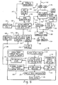
Figure 6 contains an operational flow chart of an exemplary laser altimeter and
a block diagram schematic of a system disposed on-board an aircraft and utilizing the
laser altimeter for profiling objects on the terrain forward of the aircraft during flight for
use in the guidance and control of the aircraft.
-
Figures 7A-7D illustrate various views of an enclosed housing for an alternate
non-scanning laser altimeter embodiment in accordance with the principles of the present
invention.
DETAILED DESCRIPTION OF THE INVENTION
-
Figure 1 is an illustration of an aircraft 10, which may be an UAV, for
example, on-board which a cross-track laser altimeter (not shown) is disposed. In Figure
1, the aircraft 10 is shown flying over terrain 12 which may include ground objects
projecting above the ground level in the flight path designated by the arrowed line 14.
The on-board laser altimeter transmits pulsed laser beams on the order of 2 milliradians,
for example, designated by the arrowed lines 16, from the aircraft 10 towards the ground
or terrain 12. As will become more evident from the following description, the laser
altimeter scans the pulsed laser beams 16 back and forth across a path 17 substantially
perpendicular to the ground track 18 of the aircraft which is shown more clearly in the
simple sketch of Figure 2. This scanning is known as cross-track scanning, which results
in the name cross-track laser altimeter. The laser altimeter uses a time of flight technique
in a real time environment for gathering AGL range data of terrain and objects above the
terrain suitable for aircraft flight navigation, control and data analysis. This technique
may also be used without a scanner for straight, line of sight range or distance
measurement of objects above ground level.
-
In a forward looking view configuration of the laser altimeter, the pulsed
beams 16 are transmitted at a predetermined angle, like on the order of 15°-45° to the
flight path 14 of the aircraft 10, for example, so that a range or distance to ground objects
in advance of the aircraft may be determined to augment flight controls of the aircraft for
collision avoidance, for example. In a downward looking view mode, the pulsed beams
16 are transmitted substantially perpendicular to the ground 12 to determined the
instantaneous AGL height. As the aircraft 10 moves forward in time, the pulsed beams 16
are scanned across the ground track 18 in a serpentine or sinusoidal pattern so that a two
dimensional terrain/object profile is swept by this cross scanning to the ground track 18.
As the aircraft progresses in time, a 3 dimensional, real-time spatial data set is created by
the present embodiment of the invention. For each position of scanned beam 16 in time,
position information is logged, time of flight of the laser pulse is recorded, and a
ground/object height profile data set assembled. The accumulated data from the
sinusoidal sweep of the laser scanner contains position information of objects on the
ground relative to the body axis of the aircraft 10.
-
Combining this information with GPS and inertial navigation information
obtained from aircraft avionics permits the geo-location of land features, man-made or
naturally occurring, and the detection and definition of safe flight volumes (SFVs) 20
which are defined for the present embodiment as three dimensional spaces forward and/or
below the aircraft 10 containing no obstructions (see Figure 1). The GPS and inertial data
are also used by the present embodiment to compensate for bank or pitch attitude angles
of the aircraft 10. The foregoing described information may be used to provide inputs to a
flight control system of the aircraft 10 in real-time to avoid collisions with ground
features that may represent a potential flight hazard at a future point in time as the aircraft
10 progresses forward. In addition, the ground height profile data sets may be used to
interrogate terrain features such as valleys or mountains. This laser altimeter technology
presents a significant advancement over radar altimeters as the ground registered data
contains a higher level of resolution due to the narrow beam of the laser. The present
system may be configured in a mono-static or bi-static laser altimeter approach for
scanning or non-scanning applications. All of these aspects will be explained in greater
detail herein below.
-
Figure 3 illustrates an exemplary embodiment of a cross-track laser altimeter
30 suitable for use on-board the aircraft 10 of Figures 1 and 2. The embodiment of Figure
3 comprises a mono-static configuration of optical paths, but may be modified to a bi-static
configuration as will become apparent from the following description without
deviating from the broad principles of the present invention. Referring to Figure 3, a laser
source 32 generates laser pulses at a predetermined rate, like in the range of
approximately 8K-10K pulses per second (PPS), for example, over an optical path 34.
The laser pulses may be linearly polarized with a pulse width on the order of 0.8
nanoseconds, for example. The laser source 32 may comprise a passively Q switched
autonomously operated microchip laser of the type manufactured by Northrup Gruman,
PolySci, bearing model no. DEM 1064, for example. While this laser source generates the
laser beam substantially at a wavelength of approximately 1064 nanometers (nm), it is
understood that laser beams of other wavelengths may be used in the present embodiment
just as well. For example, the laser source 32 may generate laser beams at an eye safe
wavelength which may be on the order of 1.5 micrometers.
-
A collimating lens 36 may be disposed in the path 34. The pulsed laser beam
emitted from the laser source 32 expands to approximately 4 millimeters (mm) before
being collimated by the lens 36 which passes the collimated beam to a polarizing beam
splitting cube 38. A small portion of the pulsed laser beam is split off in the cube 38 and
directed over an optical path 40 to a light detector 42, which may be an avalanche
photodetector, for example, which generates a start pulse over signal line 44 in response
thereto. An optical filter element 46 may be disposed in the optical path 40 to pass light
substantially at the wavelength of the generated laser beam. The balance of the laser beam
is passed through the cube 38 and directed along an optical path 48 to a quarter-wave
optical element 50 in which the beam is converted to circular polarization. In the present
embodiment, a fold mirror 52 is disposed in the path 48 to direct the circular polarized
beam from path 48 to a beam expander 54 that has been folded into a penta-prism
architecture as will be more fully described in connection with the embodiment of Figure
4 supra. The expanded beam, which may be magnified by a predetermined magnification,
like approximately 10X in diameter, for example, leaves the expander 54 along an optical
path 57 and enters a scanner 56, which may be a resonant scanner, for example.
-
The resonant scanner 56 may be configured to sweep the beam along a
downward path which is at an angle to the flight path of the aircraft. The downward angle
may be adjustable between 15° to 45°, for example, for a forward looking view. The
beam designated by the arrowed lines 16 is emitted from the bottom of the aircraft or
UAV 10 through a flush window 58 at the downward angle to the flight path. With the
beam directed at the downward angle, it is swept back and forth at a rate of 100 Hz or
approximately 200 lines per second via the resonant scanner 56 in the cross-track
direction from +/- 10 degrees to up to +/- 30 degrees in relation to the ground track of the
aircraft as shown in Figure 2. Echo return signals reenter the laser altimeter 30 through
window 58 and are directed back to the cube 38 along the same optical paths as used for
the transmitted pulses, i.e. mono-static configuration, except that the echo or return pulses
are reconverted to linear polarization in element 50 in a reverse linear polarization to the
transmitted pulse. At the cube 38, the return pulses are re-directed along path 40, through
the optical filter 46 to the avalanche photodiode detector 42 which produces return or stop
pulses over line 44 in response thereto.
-
Signal line 44 is coupled to a chronometer 60 which, in one embodiment, may
be driven by a time-of-flight (TOF) clock 62. The time of flight for each return pulse is
determined in chronometer 60 based on the advancement of an internal clock driven by
the TOF clock pulses between corresponding start and stop pulses from line 44. The
resulting digital TOF code of the internal clock may be recorded in the chronometer 60.
Alternatively, the chronometer 60 may include a capacitor which is charged to a voltage
between the start and stop pulses. The resulting voltage across the capacitor at the stop
pulse is converted to a digital code which may be 16 bits, for example, by an analog-to-digital
converter (A/D). The resulting digital TOF code of the A/D may be recorded in the
chronometer 60 which may be of the type manufactured by E-O Devices, bearing model
no. ECH-2, for example.
-
In either embodiment, range to an object is then determined from the digital
TOF data recorded in the chronometer 60. The TOF data is provided to a data
concentrator 64 over signal lines 66 along with a scan position signal over line 68 from
the resonant scanner 56. The data concentrator 64 determines the range for each echo
return from the corresponding TOF data thereof and gathers the range and position data
for all of the points (returns) along each line sweep to form return data profiles from
which above ground objects forward of the aircraft may be determined. For the present
embodiment, range accuracy for each point is on the order of 6 inches or better.
Information regarding the aircraft location (lat/lon), via an on-board GPS receiver, and
inertial state via an on-board INS computer, is also provided to the data concentrator 64
for the return data profiles. From the collected data, the data concentrator 64 may
compute compensated height of ground objects based on aircraft roll and/or pitch attitude,
for example. The return data profiles are output from the concentrator 64 over line 70,
preferably to the aircraft bus from which it may be obtained from the other systems of the
aircraft as will become more evident from the description found herein below.
-
While the embodiment of Figure 3 comprises a mono-static optical path
configuration, it is understood by all those skilled in the pertinent art, that such an
embodiment may be modified to permit a bi-static optical path configuration without
deviating from the broad principles of the present invention. For example, in a bi-static
configuration, the laser source 32 may provide the pulsed laser beams along one path to
the beam expander 54 and resonant scanner 56 and echo returns received from the
scanner 56 and expander 54 may be directed along a separate optical path to filter 46 and
detector 42. In such an embodiment, certain elements of the mono-static configuration,
like the beam splitter cube 38, for example, may not be needed and the optical paths may
take the form of fiber optic cables, for example.
-
Figure 4 is an illustration of an exemplary packaging of the laser altimeter
embodiment in an enclosed housing 72 having outside side dimensions of 74 and 76,
which may be approximately six inches or 15 centimeters each, for example. Reference
numerals for the elements already described for the embodiment illustrated in Figure 3
will be kept the same. Referring to Figure 4, within the housing 72, the optical elements
32, 36, 38, 50 and 52 are mounted to an optical bench (not shown) and fixedly aligned
along their respective optical paths 34 and 48. In this embodiment, the elements 42 and
46 are fixedly aligned and coupled together with element 38 in a common assembly. As
noted above the beam expander 54 may be folded into a penta-prism configuration. In this
configuration, the circularly polarized beam reflected by the fold mirror 52 enters a plano-convex
lens 78 and is expanded thereby. The expanding beam is directed to a first fold
mirror 80 which reflects the expanding beam to a second fold mirror 82 which again
reflects the expanding beam to another plano-convex lens 84. Note that the beam
continues to expand in diameter until it reaches the second plano-convex lens 84 wherein
it is re-collimated and directed to a mirrored element 86 of the resonant scanner 56. The
optical elements of the beam expander 54 and resonant scanner 56 may be mounted to the
optical bench and fixedly aligned to provide the optical paths as described hereabove and
shown in Figure 4.
-
The mirrored element 86 of the resonant scanner 56 may be of the type
described in the co-pending U.S. patent application no. 10/056,199, filed January 24,
2002, entitled "Silicon Wafer Based Rotatable Mirror" and assigned to the same assignee
as the instant application, which co-pending application being incorporated by reference
herein for providing the mirrored element in greater detail. In the present embodiment,
the mirrored element 86 may comprise a brass backplate for attaching the element 86 to
an electro-mechanical resonator unit 88 which may be of the push bar solenoid type
manufactured by LaseSys Corp., under the model no. URS-E-100, for example. The
mirrored element 86 via the brass backplate may be mounted to the resonator unit 88 by a
plurality of spring loaded mounting arms 90 and is operated by a pair of voice coils in the
unit 88 to resonate or oscillate back and forth along the path of the arrowed line 92, for
example.
-
When housing 72 is mounted to the aircraft, the resonant scanner and mirror
element are configurable in the housing 72 such that the pulsed laser beams 16 are
reflected from the mirrored element 86 through the window 58 in the housing 72 and
scanned along paths forward and downward at a predetermined angle to the flight path of
the aircraft, wherein the pulsed laser beam paths are caused to be line swept in a cross-track
motion in relation to the flight of the aircraft as described herein above.
Accordingly, the mirror element 86 receives returns of the pulsed laser beams from the
terrain and objects on the terrain forward the aircraft and reflects the returns back to the
optical elements of the laser altimeter for downstream processing thereof.
-
In the embodiment of Figure 4, a printed circuit (PC) board 94 may be
mounted to the resonant scanner 56 and contain the circuits for determining the position
of the scanner 56, TOF clock 62, the chronometer 60 and the data concentrator 64, for
example. Power for the laser source 32 may be brought into the housing 72 through an
electrical connector 96 over power lines 98. Also, power for the PC board circuits, GPS
signals and INS signals for the data concentrator 64 may be brought into the housing 72
through the connector 96 over lines 100 and the data output from the data concentrator 64
may exit the housing 72 over lines 100 as well.
-
Accordingly, the entire laser altimeter 30 may be packaged in a very small
enclosed housing 72 which may be 15 cm on each side 74 and 76 with a depth dimension
102 which may be approximately 3.5 in. or 8.75 cm, for example. The enclosed housing
72 of the present embodiment is shown in different isometric views in Figures 5A and 5B.
Referring to Figure 5B, the top of the housing 72 is fully enclosed and sealed with a plate
104. In Figure 5A, the windowed bottom 106 of housing 72 may be flush mounted to a
bottom skin surface of the aircraft 10 using mounting pads 108 which project out from the
bottoms of the sides of the housing 72. Holes are provided in the pads 108 for securing
the housing 72 to the aircraft skin using screws or rivets, for example. An opening may be
provided in the aircraft skin aligned with the windowed area 58 to allow the pulsed laser
beams and their echo returns to pass from and be received by the laser altimeter 30.
-
An exemplary operation of the laser altimeter 30 and how the return data
profiles generated and output therefrom interface with other aircraft avionics will now be
described in connection with a block flow chart shown in Figure 6. Referring to Figures 3
and 6, in block 110, the laser source 32 fires laser pulses at a rate of 8K-10K pps, for
example. In block 112, each exiting laser pulse is detected by the photo-detector 42 via
cube 38 and filter 46. Each detection produces a start or initial pulse which causes the
chronometer 60 to count in block 114 based on the TOF clock which may have a clock
rate on the order of 1x10⁹ pps, for example. When a return or echo pulse is received by
the photo-detector 42 in block 116, the count of the chronometer 60 is registered as a
TOF datum for the corresponding pulse in block 118. Thereafter, in block 120, the data
concentrator 64 generates a range from the TOF datum of each return or echo based on
aircraft position via an on-board GPS receiver and compensated for inertial states of the
aircraft, block 122. Each return pulse data profile comprises the position of the pulse in
the scan obtained from the resonant scanner 56, block 124, and the compensated range
thereof, for example. Preferably the data profiles are generated sequentially in an order
corresponding to each line sweep of the pulsed laser beam and may be generated in real
time as the corresponding return echoes are being produced. Accordingly, in block 126, a
sequential stream of return data profiles is output from the laser altimeter 30 over line
128, preferably in real time at a rate of approximately 8K-10K data points per second, i.e.
as they are being generated.
-
The stream of return data profiles over line 128 may be provided to an active
obstacle sensing unit designated by block 130 which gathers and assembles the data
profiles of a predetermined number of consecutive line sweeps to form composite data of
a three dimensional (3-D) spatial image or data set of a first predetermined area of the
ground scan. If the laser altimeter 30 directs its line scans forward of the aircraft, then the
predetermined area will be forward of the aircraft. In the present embodiment, the sensing
unit 130 assembles the data profiles of the most recent predetermined number of
consecutive line sweeps. Accordingly, as the aircraft moves along its flight path, the
spatial data set of the first predetermined area changes like a sliding window with aircraft
movement, for example. Preferably, data profiles of consecutive line sweeps are always
gathered and assembled by the unit 130 from the data stream to form a real time 3-D
image of the first predetermined area which includes data of terrain contours and object
profiles on the terrain. This assembled image is referred to herein as the cross-track scan
image of the laser altimeter 30 and is used in the determination of the safe flight volume
(SFV) 20 defined herein above in connection with Figure 1. The ground/object profile
data set of the scan image corresponding to the first predetermined area assembled by unit
130 is then output to the other aircraft avionics via the aircraft bus 132, preferably using a
flight control data concentrator.
-
In the present embodiment, this ground/object image data set, which contains
a higher level of resolution than radar derived data sets due to the narrow beam of the
laser, is used by the aircraft avionics to provide inputs to the flight control system of the
aircraft in real-time to avoid ground obstacles that may represent a potential flight hazard
at a future point in time as the aircraft progresses forward. More specifically, the high
resolution image scan profile data sets may be provided to a data concentrator 146 and
used therein to augment/enhance the digital terrain contour data sets of a data base which
may be stored on board the aircraft 10 in a memory 134, for example. This will become
more evident from the following description.
-
A GPS receiver 140 is disposed on-board the aircraft and receives signals from
the associated GPS satellite network by an antenna 142, and therefrom determines the
instantaneous latitude and longitude (lat/lon) position of the aircraft 10. The GPS receiver
140 generates a position signal representative of the aircraft position over signal line 144
which may be coupled to the laser altimeter 30 for use in assembling the return data
profiles. For example, an instantaneous aircraft position may be provided in the data
stream with the data profiles of each line sweep. Accordingly, the sense unit 130 may
utilize the return data profiles along with the associated instantaneous aircraft position
data to establish a geographical location and latitude and longitude boundaries of each
first predetermined area which is also passed along to the data concentrator 146.
-
In turn, the data concentrator 146 may utilize the geographical location and
latitude and longitude boundaries of each first predetermined area to access the database
of memory 134 via signal lines 147 to retrieve terrain contour data comprising terrain
contour data of a second predetermined area of terrain substantially consistent with the
geographic boundaries of the first predetermined area. Consequently, the terrain data set
retrieved from memory 134 may be substantially congruent in area and geometry to the
scan area data set assembled by unit 130. The two data sets are compared together in the
data concentrator 146 to identify above ground object profiles and other terrain features
of the first predetermined areas that are not in the terrain database of memory 134. The
data concentrator 146 is also operative to integrate the data sets of the first and second
predetermined areas to provide more detailed information of the terrain features and
objects on the terrain to other aircraft avionics for use in the guidance and control of the
aircraft as will become more evident from the following description.
-
This more detailed composite terrain/object information, which may be
updated and augmented in real-time, may be used to safely optimize the aircraft height
above ground data which is used along with other flight information to define the SFV in
block 148. Each defined SFV data is provided to a flight management computer 150.
Moreover, the integrated composite data set of above ground object profiles detected in
block 146 may be provided to the computer 150 over signal lines 152 for use in an
intelligent decision authority by the flight director by knowing in advance what potential
obstacles are left or right of the flight path of the aircraft before a change in flight path is
input. Also, advanced warning of changes in the object profiles or heights above ground
may be determined in computer 150 from the data set of above ground objects and such
changes may be directed to the aircraft flight control director for autonomous control.
-
If the aircraft 10 is a UAV, then prosecution of a desired mission change to the
UAV is communicated to a mission function 154 coupled to the flight management
computer 150 by commands through a satellite communication data link 156 including
antenna 158, a laser communications module 160 including a CW laser receiver 162
and/or a pulsed laser receiver 164, an RF receiver, or other communication methods, for
example. Upon acceptance of the command at the UAV, the flight management
computer (FMC) 150 can interrogate the environment, planning and executing flight
control settings to avoid contact with other ground objects. For example, the FMC 150
commands the Engine Control Unit (ECU) 166 and Flight Dynamics Control Unit (CU)
168 as necessary to satisfy the commanded mission relative to the GPS position which it
receives from receiver 140, and the INS state which it receives from the an INS computer
170. Vehicle flight control laws are satisfied to maintain the mission command or request
within the context of the Safe Flight Volume defined in block 148 and vehicle stability
limits. The cross-track profiling system may either provide the FMC 150 with a new Safe
Flight Volume each time the aircraft approaches the boundary of the current SFV or may
provide a continuously updated SFV. The frequency of SFV update is based primarily on
the aircraft speed and threat warning level of proximity. Moreover, the volume of SFV
may be periodically updated and enlarged or shrunk depending on aircraft speed,
maneuverability, altitude, density of objects, and height above ground determinations.
-
Other data measurements determined by on-board avionics systems may be
included by the data concentrator 146 in establishing the SFV. For example, a traffic alert
and collision avoidance system or TCAS 172, which may be of the type manufactured by
Goodrich Avionic Systems and referred to as SKYWATCH® , for example, may
determine other aircraft within a volume of space surrounding the aircraft. Such data may
be communicated to the data concentrator 146 over the aircraft bus 132 to take into
account such target aircraft when establishing the SFV. Another example is an active
laser obstacle and air data system 174, which may be of the type described in the co-pending
U.S. patent application no. 09/946,057, filed September 4, 2001, entitled
"Combined LOAS and LIDAR System", and assigned to the same assignee as the instant
application, the co-pending application being incorporated by reference herein for
providing greater details of the structure and operation thereof. The system 174 detects
obstacles surrounding the aircraft 10 and provides data of the position thereof. Such
obstacle data also may be provided over the aircraft bus 132 to the data concentrator 146
for use in defining the SFV. Yet another example is an active laser wind speed sensor
176, which may be of the type described in the co-pending U.S. patent application no.
09/946,048, filed September 4, 2001, entitled "System and Method Of Measuring Flow
Velocity in Three Axes", and assigned to the same assignee as the instant application, the
co-pending application being incorporated by reference herein for providing greater
details of the structure and operation thereof. The sensor 176 senses the wind speed or
velocity surrounding the aircraft and provides such data to flight controls 178 to assist in
determining navigation for obstacle/terrain avoidance.
-
Further, since the cross-track profiling system is capable of producing a range
accuracy of +/- 6 inches (15 cm) or better, a concealed target ID detector unit 180 is
included and operates to identify a target concealed by a common object. More
specifically, when an aircraft flies over the common object on the terrain, like tree foliage
, for example, a target under the canopy of the tree can not generally be seen from a plan
view of the common object by the aircraft, and is therefore, considered concealed by the
ground object. In the present embodiment, the unit 180 receives the return data profiles
from the laser altimeter 30 over signal line 128, for example, and assembles the data
profiles of a predetermined number of consecutive line sweeps forward the aircraft to
form composite data of a 3-D scan image of the common object and target concealed
thereby. The unit 180 assembles and forms the 3-D scan image for each of a plurality of
different approach flight paths. This is possible due to the detection and timing of
multiple laser radar returns from a single or common ground location. As the laser
altimeter 30 sweeps the pulsed laser beam side to side, multiple returns may be generated
by the foliage of trees, the ground, and objects between the ground and tree canopy, for
example. Thus, by flying different flight vectors over the same ground location which
may be determined by the GPS receiver 140, a dataset of elevation and position geo-located
to a master ground reference such as a map, for example, may be constructed by
the unit 180. Accordingly, each formed 3-D image provides a forward view orientation of
the common object and target concealed thereby.
-
Unit 180 is further operative to integrate the different viewed 3-D images to
form a comprehensive 3-D image of the common object which reveals the concealed
target. This is due to the view orientation changing relative to the common object or
foliage permitting detection of a portion of the concealed target in each flight direction or
vector, the target being obscured or partially obscured from view in each of the different
flight directions. When the views are combined in unit 180, the partially obscured target
from the different views may be integrated and reconstructed into a complete or near
complete image from which the unit 180 may identify the target. By tracking the common
ground location or common object with aircraft lat/lon coordinates obtained from a signal
generated from the GPS receiver 140, for example, and assembling and processing laser
return data profiles based thereon, a comprehensive 3-D image of all the data collected
may be constructed in unit 180. By sorting the data of the data stream 128 based on range
or altitude, the data can be parsed to show only returns below the tree canopy revealing
the concealed target, such as a tank or people, for example. This technique is useful in
search and rescue operations of downed military pilots or uncovering terrorist cells
operating out of remote jungle regions, for example.
-
As indicated above, another aspect of the present invention includes a non-scanning
laser altimeter embodiment which includes much the same elements as
described in connection with the scanning embodiment of Figure 3 absent the resonant
scanner 56. In this embodiment, the pulsed laser beam may pass directly from the beam
expander 54, out the window 58, and directed in a forward and downward path towards
the terrain below. Alternatively, a fold mirror may replace the scanner 56 to direct the
beam from the expander 54 through the window 58 and downward from the aircraft
along a path on the terrain forward the aircraft. The fold mirror may be steerable to direct
the laser beams along different paths along the terrain, one of which being the ground
track of the aircraft, for example. In either embodiment, the time of flight of the laser
pulse or range is determined by the chronometer 60 as an above ground level
measurement and provided to the flight management computer 150 (see Figure 6),
preferably over the aircraft bus 132. This measurement may be compensated for aircraft
roll and pitch attitude in the data concentrator 64 as described herein above or, in the
alternative, corrected for slant range angle in the flight management computer 150 to
compensate for roll and pitch of the aircraft. As described above, the data concentrator 64
outputs a stream of return data profiles over line 128 to the active obstacle sensing unit
130.
-
However, in the non-scanning laser altimeter embodiment, the stream of return
data profiles over line 128 does not represent a cross-track scan, but rather represents the
terrain and objects on the terrain along a ground path consistent with the flight path of the
aircraft. The unit 130 gathers and assembles a predetermined number of successive data
profiles to form composite data of a three dimensional (3-D) spatial image or data set of a
first predetermined ground path. If the non-scanning laser altimeter directs its laser beams
forward of the aircraft, then the predetermined path will be forward of the aircraft. In the
present embodiment, the sensing unit 130 assembles the data profiles of the most recent
predetermined number of successive data profiles. Accordingly, as the aircraft moves
along its flight path, the spatial data set of the first predetermined path changes like a
sliding window with aircraft movement, for example. Preferably, data profiles of
successive data profiles are always gathered and assembled by the unit 130 from the data
stream to form a real time 3-D image of the first predetermined path which includes data
of terrain contours and object profiles in the terrain path. The ground/object profile data
set of the scan path corresponding to the first predetermined path assembled by unit 130
is then output to the other aircraft avionics via the aircraft bus 132, for example, for
further processing therein.
-
A suitable housing 190 for the non-scanning laser altimeter embodiment is
shown in various views in Figures 7A-7D. Figures 7A, 7B, and 7C shown the housing
190 in top, side and profile views, respectively, and Figure 7D shows the housing 190 in
an isometric view. Note that the elements of the laser altimeter may be sealed within the
housing 190 by a top plate 192 which is affixed to the housing by a plurality of screws,
for example. An electrical connector 194 is disposed at one side of the housing 190 for
providing connections for electrical power and input and output signals therethrough. A
windowed area 196 is disposed at the bottom of the housing for passing the laser beams
from the housing and receiving echoes therefrom.
-
Referring to Figures 7A-7D, the housing 190 is approximately 7 inches or 17.5
cm in length, 2.25 in. or 5.6 cm in width and 2.5 in. or 6.25 cm in height, and includes an
approximate 0.5 in or 1.25 cm lip 198 around the periphery of bottom plate thereof
through which holes are provided to secure the housing 190 to the bottom skin surface of
the aircraft by screws or rivets, for example. An opening is provided in the bottom skin
surface aligned with the windowed area 196 for passing the laser beams 16 from the
aircraft as shown in Figure 1.
-
While the present invention has been described herein above through the use
of various embodiments, it is understood that these embodiments are provided merely by
way of example and are not intended to be limiting to the invention in any way, shape or
form. Rather, the present invention should be construed in breadth and broad scope by the
recitation of the claims appended hereto.