EP1440671A2 - An actuating device for catheters - Google Patents
An actuating device for catheters Download PDFInfo
- Publication number
- EP1440671A2 EP1440671A2 EP03029555A EP03029555A EP1440671A2 EP 1440671 A2 EP1440671 A2 EP 1440671A2 EP 03029555 A EP03029555 A EP 03029555A EP 03029555 A EP03029555 A EP 03029555A EP 1440671 A2 EP1440671 A2 EP 1440671A2
- Authority
- EP
- European Patent Office
- Prior art keywords
- slider
- slide
- toothing
- travel
- casing
- Prior art date
- Legal status (The legal status is an assumption and is not a legal conclusion. Google has not performed a legal analysis and makes no representation as to the accuracy of the status listed.)
- Granted
Links
- 230000033001 locomotion Effects 0.000 claims abstract description 44
- 230000007246 mechanism Effects 0.000 claims abstract description 15
- 230000005540 biological transmission Effects 0.000 claims abstract 5
- 230000000295 complement effect Effects 0.000 claims description 5
- 230000002093 peripheral effect Effects 0.000 claims description 4
- 230000015572 biosynthetic process Effects 0.000 claims description 3
- MEYZYGMYMLNUHJ-UHFFFAOYSA-N tunicamycin Natural products CC(C)CCCCCCCCCC=CC(=O)NC1C(O)C(O)C(CC(O)C2OC(C(O)C2O)N3C=CC(=O)NC3=O)OC1OC4OC(CO)C(O)C(O)C4NC(=O)C MEYZYGMYMLNUHJ-UHFFFAOYSA-N 0.000 description 14
- 230000000694 effects Effects 0.000 description 7
- 238000006073 displacement reaction Methods 0.000 description 6
- 230000009471 action Effects 0.000 description 3
- 238000000034 method Methods 0.000 description 3
- 230000004323 axial length Effects 0.000 description 2
- 230000009286 beneficial effect Effects 0.000 description 2
- 238000010276 construction Methods 0.000 description 2
- 230000008878 coupling Effects 0.000 description 2
- 238000010168 coupling process Methods 0.000 description 2
- 238000005859 coupling reaction Methods 0.000 description 2
- 230000009977 dual effect Effects 0.000 description 2
- 238000005755 formation reaction Methods 0.000 description 2
- 238000002513 implantation Methods 0.000 description 2
- 238000011065 in-situ storage Methods 0.000 description 2
- 230000002411 adverse Effects 0.000 description 1
- 230000003321 amplification Effects 0.000 description 1
- 238000002399 angioplasty Methods 0.000 description 1
- 230000008901 benefit Effects 0.000 description 1
- 239000011248 coating agent Substances 0.000 description 1
- 238000000576 coating method Methods 0.000 description 1
- 238000007887 coronary angioplasty Methods 0.000 description 1
- 238000011010 flushing procedure Methods 0.000 description 1
- 239000000463 material Substances 0.000 description 1
- 238000003199 nucleic acid amplification method Methods 0.000 description 1
- 230000003252 repetitive effect Effects 0.000 description 1
- 210000003813 thumb Anatomy 0.000 description 1
Images


Classifications
-
- A—HUMAN NECESSITIES
- A61—MEDICAL OR VETERINARY SCIENCE; HYGIENE
- A61F—FILTERS IMPLANTABLE INTO BLOOD VESSELS; PROSTHESES; DEVICES PROVIDING PATENCY TO, OR PREVENTING COLLAPSING OF, TUBULAR STRUCTURES OF THE BODY, e.g. STENTS; ORTHOPAEDIC, NURSING OR CONTRACEPTIVE DEVICES; FOMENTATION; TREATMENT OR PROTECTION OF EYES OR EARS; BANDAGES, DRESSINGS OR ABSORBENT PADS; FIRST-AID KITS
- A61F2/00—Filters implantable into blood vessels; Prostheses, i.e. artificial substitutes or replacements for parts of the body; Appliances for connecting them with the body; Devices providing patency to, or preventing collapsing of, tubular structures of the body, e.g. stents
- A61F2/95—Instruments specially adapted for placement or removal of stents or stent-grafts
- A61F2/9517—Instruments specially adapted for placement or removal of stents or stent-grafts handle assemblies therefor
-
- A—HUMAN NECESSITIES
- A61—MEDICAL OR VETERINARY SCIENCE; HYGIENE
- A61M—DEVICES FOR INTRODUCING MEDIA INTO, OR ONTO, THE BODY; DEVICES FOR TRANSDUCING BODY MEDIA OR FOR TAKING MEDIA FROM THE BODY; DEVICES FOR PRODUCING OR ENDING SLEEP OR STUPOR
- A61M25/00—Catheters; Hollow probes
- A61M25/01—Introducing, guiding, advancing, emplacing or holding catheters
- A61M25/0105—Steering means as part of the catheter or advancing means; Markers for positioning
- A61M25/0113—Mechanical advancing means, e.g. catheter dispensers
Definitions
- the present invention relates to devices for actuating catheters according to the preamble of Claim 1.
- catheters described in the documents in question are to a major extent designed to be used for placing and splaying out in situ stents, such as stents for angioplasty, in particular stents of the self-expanding type.
- the object of the present invention is to provide a device for actuating catheters that will be able to overcome the drawbacks referred to previously and to meet the aforesaid need to allow the criteria with which the operation is carried out to be left totally to the operator.
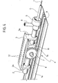
- the reference number 1 designates as a whole a device which can be used for actuating a catheter (not illustrated as a whole) comprising two parts, upon which-in the stage of use of the catheter itself-it is necessary to impart a relative movement.
- the catheter in question may consist of a catheter for implantation and splaying-out in situ of stents of the self-expanding type.
- An extended illustration of the characteristics of stents of this nature and of the corresponding catheters is provided in the documents of the known art cited in the introductory part of the present description.
- the function of the device 1 illustrated herein is to enable the sheath or tunic G to perform, with respect to the element T, a travel of recession in the direction of the arrow designated by R in Figure 2.
- the solution described in what follows envisages in fact that the sheath or tunic G will perform a movement of recession with respect to the element T, which is kept in a position that is substantially fixed with respect to the casing of the device 1, with simple kinematic variants (within the reach of a person skilled in the sector) the solution described herein can be adapted so as to obtain the complementary result, enabling the tubular element T to advance with respect to the sheath G, which is kept in a position substantially fixed with respect to the casing of the device 1, or else to cause the travel of relative displacement in the direction of the arrow R to be obtained as a result of a combined movement both of the sheath or tunic G and of the element T.
- the configuration of the distal end of the catheter could be such as to envisage an at least partly complementary arrangement: in either case, the details of construction of the distal end of the catheter are in themselves irrelevant for the purposes of understanding and implementing the solution described herein, the possibilities of use of which are altogether general.
- sheath G is represented herein in a cutaway view so as to highlight how the travel of recession R is performed. It is in fact altogether evident that the sheath G extends with substantial continuity, coating the element T throughout its length up to the distal end of the catheter (not visible in the annexed drawings).
- the device 1 has a containment casing having a generically elongated shape, represented herein with a dashed line, with the exception of the end wall, designated by 1a.
- the figures of the attached drawings illustrate a device 1 with a casing having a shape that substantially may be likened to a parallelepiped.
- the shape of the aforesaid casing can be of any type whatsoever.
- this shape can be defined according to ergonomic criteria so as to enable a convenient grip and manipulation of the device 1 on the part of the operator who must use the device 1.
- the device 1 has one front end, the one in which the sheath G set on top of the element T is represented, and one rear end, opposite to the preceding one.
- the end wall 1a (or any other part of the casing of the device 1) carries a guide element, such as a bushing 1b functioning as supporting element for the element T.
- a guide element such as a bushing 1b functioning as supporting element for the element T.
- the element T is fixed to the guide element 1b so as to be in effect fixed to the casing of the device 1.
- This connection is evidently designed to facilitate the operation of catheterization, performed according to known criteria (for example, resorting to the known techniques, such as "over the wire” technique or "rapid exchange” technique).
- the slide 2 is basically constituted by a tubular element (preferentially made, like the other parts of the device 1, of a plastic material compatible with use in the medical or surgical fields, in particular in the sterile field), which is fitted on the element T so as to be able to slide longitudinally within the device 1 along an axis X1 corresponding in effect to the axis of the element T, which extends longitudinally within the casing of the device 1.
- a tubular element preferentially made, like the other parts of the device 1, of a plastic material compatible with use in the medical or surgical fields, in particular in the sterile field
- Fixing of the front end of the tubular slide T to the sheath G is made in a position corresponding to a ring nut 5, to which there is usually associated a connection element 6 for flushing the catheter.
- Movement of the slide 2 along the axis X1 is rendered regular by the presence of a wheel, and preferably two wheels 7 mounted on hub parts 8, which project laterally from the body of the slide 2.
- the overall structure of the slide 2 illustrated herein may thus approximately be likened to the structure of a wheel-barrow or cart.
- the wheel or wheels 7 runs (run) in grooves 9 provided along the end wall 1a of the wall of the casing.
- the wheels 7 are in actual fact gearwheels, provided with an external toothing 7a designed to co-operate with a corresponding rack toothing, provided along the groove or grooves 9.
- the slider 3 consists of a board which is able to move along a slit 1c provided in the top wall of the casing 1.
- the operator who actuates the catheter is able, for example, to grip the casing of the device 1 and to rest his thumb on the slider 3, maintained in the position illustrated in Figure 1, the aim being to control gradually the recession of the slider 3 itself, as schematically illustrated in Figure 2.
- the slider 3 in actual fact has a gantry-shaped or ⁇ -shaped structure of which the board mentioned previously forms the web part.
- This web part carries at its end two side tab parts 3a and 3b, provided at their distal ends with openings 10 having a diameter slightly greater than the external diameter of the body of the slide 2.
- the slider 3 can thus be fitted on the slide 2 so as to be mobile with respect to the slide 2 itself in the direction of the axis X1.
- this movement is performed between an advanced position, represented in Figure 1, and a retracted position, represented in Figure 2.
- These two positions are basically identified by bearing, respectively with the side part 3b and the side part 3a, upon a central prismatic core 11 of the slide 2. From the core 11 there branch off laterally the pins 8, on which the gearwheels 7 are mounted.
- the guides 12 may substantially be likened to the guides 9, with the evident difference that their respective channel formations are open in opposite directions, towards one another.
- the gearwheel or gearwheels 7 constitutes (constitute) the central element of the speed-change mechanism aimed at causing, in different portions of the travel of movement in the direction of the arrow R, the drive ratio between the slider 3 and the slide 2 to assume at least two distinct values.
- This second effect is particularly beneficial because it reduces the effort that the operator needs to make to overcome the friction initially opposed by the sheath or tunic G to the movement of recession.
- the speed-change mechanism described starts to operate with unit drive ratio, in the sense that, receding further in the direction of the rear end of the device 1, the slider 3 pulls along with it the slide 2 by adopting, in this case, a unit drive ratio, so that the amount of travel and rate of displacement of the slider 3 and of the slide 2 are identical to one another.
- the aforesaid condition of direct coupling between the slider 3 and the slide 2 is usually maintained up to completion of the travel of recession of the sheath G.
- the solution described herein can be developed by enabling the speed-change mechanism of the device-instead of having just two possible drive ratios (i.e., the first 50% demultiplication and the second direct-drive ratio) - to envisage a greater number of different speed ratios.
- the aforesaid speed-change mechanism will envisage a third step of operation with a speed-multiplication ratio, i.e., in conditions such that the movement of the slide 2 (and consequently the movement of retraction of the sheath G) will occur at a speed higher than the speed imparted by the operator upon the slider 3.
- such a device would perform, instead of the function described previously (demultiplication of the speed imposed by the operator, with the slide 2 and the sheath G that move with a speed equal to half that applied to the slider 3 by the operator), an exactly opposite function of multiplication (with the part 3a and the sheath G connected thereto, which move at a speed twice that of the speed imposed by the operator on the pin or pins 8).
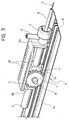
- the slider 3 is constituted in practice by a sort of carriage which is able to move along the casing of the device under the action exerted by the operator by acting upon a tab 13 projecting on the outside of the casing itself.
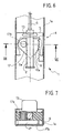
- the carriage of the slider carries with it a toothed sector 17, which meshes, with its external toothing 17a, with the toothing or rack 9 provided on the wall 1a of the casing.
- the toothed sector 17 (having for example an angular opening of approximately 50°) has a grooved central pin 17b, which has a dual function.
- the pin 17b functions as a gearwheel that meshes with a respective toothing or rack 2a provided on one side of the slide 2, made simply as a prismatic guide that slides longitudinally through and with respect to the slider 3.
- the radius of the external toothing 17a of the toothed sector 17 is evidently greater than the radius of the toothing constituted by the external grooves of the pin 17b.
- the overall effect achieved will be a recession of the sheath G, connected to the slide 2, by an amount given by the difference between the recession of the slider 3 and the relative advance of the slide 2 with respect to the slider 3 itself.
- the amount of this relative advance is determined by the ratio between the radius of the toothing 17a and the radius of the grooved pin 17b, thus being selectable within a wide range of variation.
Abstract
- a slide (2) which can be connected to one (G) between the first part (T) and the second part (G) of the catheter;
- a slider (3), which can be actuated for moving the slide (2) and performing the aforesaid travel of relative movement; and
- a speed-change mechanism (7, 9, 12), which is set between the slider (3) and the slide (2) and is able to perform transmission of the movement between the slider (3) and the slide (2).
Description
- The present invention relates to devices for actuating catheters according to the preamble of
Claim 1. - The corresponding known art is exemplified by documents such as US-B-6 391 051, US-B-6 375 676, US-B-6 238 402, US-B-6 146 415, US-A-6 019 778, US-A-5 201 757, and also WO-A-00/10486 and DE-A-198 19 634.
- The catheters described in the documents in question are to a major extent designed to be used for placing and splaying out in situ stents, such as stents for angioplasty, in particular stents of the self-expanding type.
- With a certain degree of simplification, but with substantial adherence to the actual situation, it may be stated that, in the solutions considered above, the relative movement designed to disengage the stent from the element or elements that the keep it in a radially contracted condition is left practically completely-above all as regards the speed for carrying the operation out-to the control of the operator.
- The ever increasing clinical experience developed in the use of stents of this nature demonstrates, however, that this solution is not altogether free from drawbacks.
- It is found, for example, that the action of splaying out the stent - performed gradually at one end of the stent and then involving the stent as a whole-must usually be performed in its initial steps in a delicate and gradual way. Precisely in these initial steps, the operator must, however, overcome quite a high initial force of friction, represented by the need to overcome the resistance opposed by the means of containment of the stent. Usually, these consist of a tubular tunic fitted on the stent that must be retracted by causing it to slide axially on the stent so as to uncover and gradually free the stent itself.
- Consequently, it may happen that the force applied by the operator in the initial step of the operation of splaying-out, in a way commensurate with the need to start the movement of retraction of the tunic with respect to the stent, will be excessive in the subsequent steps of splaying-out. All this entails possible adverse effects, above all when the stent in question is a stent for coronary angioplasty of small axial length, for example about ten millimetres.
- In the case of stents of a substantial axial length (for instance, certain peripheral stents), it may instead happen that the movement of disengagement of the tunic from the stent will end up being executed at an excessively slow speed.
- More in general, there is felt the need to provide a guide for the operator in carrying out the operation of splaying out the stent precisely by the device for actuating the catheter, thus preventing the criteria whereby the operation is carried out from being entrusted altogether to the operator.
- The object of the present invention is to provide a device for actuating catheters that will be able to overcome the drawbacks referred to previously and to meet the aforesaid need to allow the criteria with which the operation is carried out to be left totally to the operator.
- According to the present invention, this object is achieved thanks to a device having the characteristics referred to specifically in the ensuing claims.
- It will be appreciated that in the definition of the invention, reference is made herein to actuating catheters understood in a general sense. Even though the present invention has been developed with particular attention paid to its possible use for actuating catheters for the application of stents, and in particular self-expanding stents, it may be used to advantage together with catheters of any type in which it is in any case necessary, for use of the catheter, to perform a relative movement of a number of parts of the catheter itself.
- The invention will now be described, purely by way of non-limiting example, with reference to the annexed drawings, in which:
- Figures 1 and 2 illustrate, in two perspective views that are substantially equivalent to one another, two different possible positions of operation of a device according to the invention;
- Figures 3, 4 and 5 illustrate, at a slightly enlarged scale, some details of the device of Figures 1 and 2, represented also in this case in different possible positions of operation;
- Figure 6 illustrates a possible variant embodiment of the invention; and
- Figure 7 is a cross-sectional view according to the line VII-VII of Figure 6.
- In the figures of the annexed drawings, the
reference number 1 designates as a whole a device which can be used for actuating a catheter (not illustrated as a whole) comprising two parts, upon which-in the stage of use of the catheter itself-it is necessary to impart a relative movement. - Just to provide an example, and with reference to the field of use of the
device 1 currently considered as being preferential, the catheter in question may consist of a catheter for implantation and splaying-out in situ of stents of the self-expanding type. An extended illustration of the characteristics of stents of this nature and of the corresponding catheters is provided in the documents of the known art cited in the introductory part of the present description. - As regards the purposes of the present application, in what follows it will be assumed that the parts of the catheter upon which it is necessary to impart a relative movement are constituted by:
- a filiform guide element T, consisting typically of a microtube, which is in turn designed to slide on the so-called guide wire of the catheter itself; and
- a sheath or tunic G mounted on the element T so as to be able to slide longitudinally along,the element T itself.
- In the course of the ensuing description it will be assumed that the relative movement in question must take place between a first relative position, in which the sheath or tunic G occupies an advanced position with respect to the element T, and a second position in which, as a result of a movement of recession with respect to the element T, the sheath G recedes and uncovers, enabling its splaying-out, a self-expanding stent fitted to the distal end of the element T.
- All this occurs, as has already been said, according to criteria that are widely known in the art and hence such as not to require a detailed description herein.
- For the present purpose, the function of the
device 1 illustrated herein is to enable the sheath or tunic G to perform, with respect to the element T, a travel of recession in the direction of the arrow designated by R in Figure 2. - Persons skilled in the art will appreciate immediately the fact that the aforesaid movement is to be viewed basically as a relative movement between the element T and the sheath or tunic G.
- Whilst the solution described in what follows envisages in fact that the sheath or tunic G will perform a movement of recession with respect to the element T, which is kept in a position that is substantially fixed with respect to the casing of the
device 1, with simple kinematic variants (within the reach of a person skilled in the sector) the solution described herein can be adapted so as to obtain the complementary result, enabling the tubular element T to advance with respect to the sheath G, which is kept in a position substantially fixed with respect to the casing of thedevice 1, or else to cause the travel of relative displacement in the direction of the arrow R to be obtained as a result of a combined movement both of the sheath or tunic G and of the element T. - Previously, implicit reference was made to a situation in which it is assumed that the stent (not illustrated) is fitted on the element T and there withheld in a radially contracted position by the sheath or tunic G, so that the stent will expand as it disengages from the sheath or tunic G.
- The configuration of the distal end of the catheter could be such as to envisage an at least partly complementary arrangement: in either case, the details of construction of the distal end of the catheter are in themselves irrelevant for the purposes of understanding and implementing the solution described herein, the possibilities of use of which are altogether general.
- It will moreover be appreciated that the sheath G is represented herein in a cutaway view so as to highlight how the travel of recession R is performed. It is in fact altogether evident that the sheath G extends with substantial continuity, coating the element T throughout its length up to the distal end of the catheter (not visible in the annexed drawings).
- In the example of embodiment illustrated herein (which, it must be recalled, is nothing more than an example), it is envisaged that the
device 1 has a containment casing having a generically elongated shape, represented herein with a dashed line, with the exception of the end wall, designated by 1a. - In a specific way, the figures of the attached drawings illustrate a
device 1 with a casing having a shape that substantially may be likened to a parallelepiped. Provided that certain, essential functional needs are respected, such as the possibility for the operator to gain access to the control members of the device, the shape of the aforesaid casing can be of any type whatsoever. In particular, this shape can be defined according to ergonomic criteria so as to enable a convenient grip and manipulation of thedevice 1 on the part of the operator who must use thedevice 1. - In the example of embodiment illustrated herein, the
device 1 has one front end, the one in which the sheath G set on top of the element T is represented, and one rear end, opposite to the preceding one. - In an area corresponding to the aforesaid rear end, the
end wall 1a (or any other part of the casing of the device 1) carries a guide element, such as a bushing 1b functioning as supporting element for the element T. It will be appreciated that usually the element T is fixed to theguide element 1b so as to be in effect fixed to the casing of thedevice 1. This connection is evidently designed to facilitate the operation of catheterization, performed according to known criteria (for example, resorting to the known techniques, such as "over the wire" technique or "rapid exchange" technique). - In basic terms, the solution described herein envisages the presence in the
device 1 of three elements: - a
slide 2, connected to the sheath G so as to enable it to be drawn along in the travel of recession in the direction of the arrow R; - a
slider 3, constituted by an element accessible from outside thecasing 1, designed to enable the operator to control the movement of recession of theslide 2, to which the sheath G is connected; and - a speed-
change mechanism 4, kinematically set between theslide 2 and theslider 3 so as to provide at least two different drive ratios during the movement that causes theslide 2 to draw along with it the sheath G in the travel of recession in the direction of the arrow R. - In the example of embodiment illustrated herein, the
slide 2 is basically constituted by a tubular element (preferentially made, like the other parts of thedevice 1, of a plastic material compatible with use in the medical or surgical fields, in particular in the sterile field), which is fitted on the element T so as to be able to slide longitudinally within thedevice 1 along an axis X1 corresponding in effect to the axis of the element T, which extends longitudinally within the casing of thedevice 1. - Fixing of the front end of the tubular slide T to the sheath G is made in a position corresponding to a
ring nut 5, to which there is usually associated aconnection element 6 for flushing the catheter. - Movement of the
slide 2 along the axis X1 is rendered regular by the presence of a wheel, and preferably twowheels 7 mounted onhub parts 8, which project laterally from the body of theslide 2. The overall structure of theslide 2 illustrated herein may thus approximately be likened to the structure of a wheel-barrow or cart. - The wheel or
wheels 7 runs (run) ingrooves 9 provided along theend wall 1a of the wall of the casing. For reasons that will emerge more clearly from what follows, thewheels 7 are in actual fact gearwheels, provided with anexternal toothing 7a designed to co-operate with a corresponding rack toothing, provided along the groove orgrooves 9. - In the exemplary embodiment illustrated herein, the
slider 3 consists of a board which is able to move along a slit 1c provided in the top wall of thecasing 1. In this way, the operator who actuates the catheter is able, for example, to grip the casing of thedevice 1 and to rest his thumb on theslider 3, maintained in the position illustrated in Figure 1, the aim being to control gradually the recession of theslider 3 itself, as schematically illustrated in Figure 2. - Under closer examination, the
slider 3 in actual fact has a gantry-shaped or Π-shaped structure of which the board mentioned previously forms the web part. This web part carries at its end twoside tab parts openings 10 having a diameter slightly greater than the external diameter of the body of theslide 2. - As may be immediately noted from the figures, the
slider 3 can thus be fitted on theslide 2 so as to be mobile with respect to theslide 2 itself in the direction of the axis X1. - In particular, this movement is performed between an advanced position, represented in Figure 1, and a retracted position, represented in Figure 2. These two positions are basically identified by bearing, respectively with the
side part 3b and theside part 3a, upon a centralprismatic core 11 of theslide 2. From thecore 11 there branch off laterally thepins 8, on which thegearwheels 7 are mounted. - Designating by 3a and 3b the side parts of the
slider 3 facing, respectively, thering nut 5, where the sheath G is connected to theslide 2 and the bushing 16, where the element T is fixed: - the advanced position of the
slider 3 is reached when theelement 3b is bearing upon the prismatic core 11 (see Figure 1); and - the retracted position of the slider is instead
reached when the
element 3a is bearing upon the same prismatic element 11 (see Figure 2). - On the face of the
board 3 of the slider facing the wheel orwheels 7 there are made one or tworack guides 12. Theguides 12 may substantially be likened to theguides 9, with the evident difference that their respective channel formations are open in opposite directions, towards one another. - The main difference is, however, represented by the fact that, as will be appreciated better from the enlarged views of Figures 3 to 5, the rack or each
rack 12 extends only at the rear end of the board part of theslider 3, whilst advancing towards the front end of theboard 3 itself, the channel formations with theracks 12 assume simply the appearance of smooth-walled guide tracks which, in a preferred way, move away from the wheel orwheels 7, disengaging completely therefrom theexternal ring gear 7a. - The gearwheel or
gearwheels 7 constitutes (constitute) the central element of the speed-change mechanism aimed at causing, in different portions of the travel of movement in the direction of the arrow R, the drive ratio between theslider 3 and theslide 2 to assume at least two distinct values. - In particular, when the
slider 3 is in the advanced position illustrated in Figure 1, the gearwheel orgearwheels 7 is (are) found with its (their)external ring gear 7a meshing, respectively: - with a
rack 9 provided in theend wall 1a of thecasing 1; and - with a
rack 12 provided on the bottom wall of theboard part 3 of theslider 1. - In these conditions, between the
slider 3 and theslide 2 there exists a drive ratio 1:2 in the sense that each unit length travelled by theslider 3 results in a homologous displacement of theslide 2 by an amount equal exactly to half of the distance travelled by the slider 3: this fact is evident since the pin or pins 8 is (are) found in effect half way between theracks - These conditions of operation are usually determined when, once the distal end of the catheter has been localized on the implantation site, there begins the operation of splaying out the stent by causing the sheath G to slide gradually, so disengaging the stent accordingly.
- The presence of the aforesaid drive ratio-in the sense of a demultiplication-causes the movement imparted by the operator by acting on the board of the
slider 3 to be subjected to demultiplication. - This fact has a dual beneficial effect:
- in the first place, the movement of retraction of the sheath or tunic G with respect to the element T is rendered extremely gradual, further increasing the delicacy with which this movement is brought about by the operator; and
- in the second place, the demultiplication of the
amount of displacement results in an amplification (in
practice, in a doubling) of the tensile force exerted
by the
slide 2 on the sheath G with respect to the homologous force exerted by the operator on the board part of theslider 3. - This second effect is particularly beneficial because it reduces the effort that the operator needs to make to overcome the friction initially opposed by the sheath or tunic G to the movement of recession.
- The conditions of kinematic coupling just described, with the ratio of demultiplication of the speed of displacement described previously, is maintained for a fair extent of the subsequent movement of recession of the slider 3 (see Figure 4), until the condition represented in Figure 5 is reached.
- This is a condition in which, simultaneously:
- the
side element 3a of theslider 3 is brought to bear upon theprismatic core 11 of theslide 2; and - the wheel or
wheels 7 is/are disengaged with theirexternal toothing 7a from the rack or racks 12 provided on the bottom face of the board part of theslider 3. - Once these conditions have been reached, the speed-change mechanism described starts to operate with unit drive ratio, in the sense that, receding further in the direction of the rear end of the
device 1, theslider 3 pulls along with it theslide 2 by adopting, in this case, a unit drive ratio, so that the amount of travel and rate of displacement of theslider 3 and of theslide 2 are identical to one another. - In these conditions, given the same speed of displacement backwards of the
slider 3 effected by the operator, the movement of recession of the sheath G (controlled by theslide 2, to which the sheath G is attached by means of the ring nut 5) is far more rapid than occurred previously, i.e., when the drive mechanism located between theslider 3 and theslide 2 applied the ratio of demultiplication described previously. - The aforesaid condition of direct coupling between the
slider 3 and theslide 2 is usually maintained up to completion of the travel of recession of the sheath G. - As already mentioned previously, the solution described herein can be developed by enabling the speed-change mechanism of the device-instead of having just two possible drive ratios (i.e., the first 50% demultiplication and the second direct-drive ratio) - to envisage a greater number of different speed ratios.
- For example, above all in view of its use with stents having quite considerable longitudinal dimensions, it is possible to consider that, in addition to a first step of operation with a speed-demultiplication ratio and a second step of direct drive, the aforesaid speed-change mechanism will envisage a third step of operation with a speed-multiplication ratio, i.e., in conditions such that the movement of the slide 2 (and consequently the movement of retraction of the sheath G) will occur at a speed higher than the speed imparted by the operator upon the
slider 3. - Once again, as an alternative or in addition to a speed-change mechanism with discrete ratios, it is possible to use, in the framework of a device of the type described, a speed-change device having a ratio that is variable in a continuous way.
- These possible variant embodiments prove particularly attractive in the case where the aim is to enable the criteria with which the operation of splaying out the stent is performed to be subtracted, at least in part, from the direct control of the operator, the aim being to enable the operation in question - performed according to criteria in effect imposed by the actuating device of the catheter - to be performed in a repetitive way, determined according to uniform modalities, by different operators.
- Consequently, it is understandable that the solution described herein may be implemented by resorting to speed-change mechanisms of any type known in the art and/or by modifying the functions of the various elements described previously.
- For example, with reference to the same device structure illustrated in the annexed drawings, it is possible to hypothesize a variant embodiment in which the
slide 2 and theslider 3 reverse their respective roles, envisaging that: - the sheath or tunic G will be connected, instead
of to the
slide 2, to thepart 3a; and - the pin or pins 8, and not the
board part 3, will be associated to the slider designed to be actuated by the operator. - In the first stage of operation, such a device would perform, instead of the function described previously (demultiplication of the speed imposed by the operator, with the
slide 2 and the sheath G that move with a speed equal to half that applied to theslider 3 by the operator), an exactly opposite function of multiplication (with thepart 3a and the sheath G connected thereto, which move at a speed twice that of the speed imposed by the operator on the pin or pins 8). - Yet another variant embodiment is illustrated in Figures 6 and 7, where parts that are identical or functionally equivalent to the ones described previously have been designated by the same reference numbers.
- In the variant illustrated in Figures 6 and 7, the
slider 3 is constituted in practice by a sort of carriage which is able to move along the casing of the device under the action exerted by the operator by acting upon atab 13 projecting on the outside of the casing itself. - The carriage of the slider carries with it a
toothed sector 17, which meshes, with itsexternal toothing 17a, with the toothing orrack 9 provided on thewall 1a of the casing. - The toothed sector 17 (having for example an angular opening of approximately 50°) has a grooved
central pin 17b, which has a dual function. - Firstly, as a pin, it extends through the body of the
slider 3 and causes thesector 17 to be drawn along by theslider 3 whilst being able to rotate with respect thereto. - Secondly, with its peripheral toothing, the
pin 17b functions as a gearwheel that meshes with a respective toothing orrack 2a provided on one side of theslide 2, made simply as a prismatic guide that slides longitudinally through and with respect to theslider 3. - The radius of the
external toothing 17a of thetoothed sector 17 is evidently greater than the radius of the toothing constituted by the external grooves of thepin 17b. - Consequently, when the
slider 3 is retracted (movement from the top downwards, as viewed in Figure 6), the engagement of thetoothing 17a with therack 9 causes thetoothed sector 17 to turn (in a counterclockwise direction, as viewed in Figure 6), so causing a relative advance of theslide 2 with respect to the body of theslider 3. - However, since the
slider 3 in turn recedes under the action of the operator, the overall effect achieved will be a recession of the sheath G, connected to theslide 2, by an amount given by the difference between the recession of theslider 3 and the relative advance of theslide 2 with respect to theslider 3 itself. The amount of this relative advance is determined by the ratio between the radius of thetoothing 17a and the radius of thegrooved pin 17b, thus being selectable within a wide range of variation. - It will moreover be appreciated that the individual details of embodiment described and illustrated herein with reference to a specific example of embodiment may be freely transposed also to the other examples of embodiment.
- For this reason, without prejudice the inventive principle, the details of construction and the embodiments may vary widely with respect to what is described and illustrated herein, without thereby departing from the scope of the present invention.
Claims (14)
- An actuating device for catheters comprising at least one first part (T) and one second part (G), which are able to perform a travel (R) of relative movement, characterized in that comprises:a slide (2) which can be connected to one (G) of said first part (T) and said second part (G) of the catheter;a slider (3), which can be actuated for moving said slide (2) and performing said travel of relative movement; anda speed-change mechanism (4), which is set between said slider (3) and said slide (2).
- The device according to Claim 1, characterized in that said speed-change mechanism is able to perform the transmission of the movement between said slider (3) and said slide (2) with at least two drive ratios that are different in successive parts of said travel of relative movement.
- The device according to Claim 2, characterized in that said speed-change mechanism (4) comprises:a member for transmission of motion (7), which co-operates with said slider (3) and said slide (2) for a part of said travel of relative movement until one given position of said travel of relative movement is reached; it being possible for said member for transmission of motion (7) to be disengaged (12) from at least one between said slider (3) and said slide (2) until said given position of said travel of relative movement is reached; andcomplementary contrast elements (3a, 11) carried by said slider (3) and by said slide (2), said complementary elements coming to bear upon one another substantially in a position corresponding to said given position of said travel of relative movement, so as to obtain a ratio of drawing between said slider (3) and said slide (2).
- The device according to any one of the preceding claims, characterized in that said speed-change mechanism (4) comprises at least one rotating body (7; 17) carried by one (2 respectively 3) between said slider (3) and said slide (2) and having a toothing (7a; 17b) which is able to engage a respective toothing (12; 2a) provided in the other (3 respectively 2) between said slider (3) and said slide (2); said at least one rotating body (7; 17) likewise operating in a relationship of meshing with a further toothing (9) carried by a part of casing (1a) of said actuating device.
- The device according to Claim 3 and Claim 4, characterized in that, when said given position of said travel of relative movement is reached, the toothing (7a; 17a) of said at least one rotating body (7; 17) disengages from at least one (12) between said respective toothing (12) and said further toothing (9).
- The device according to Claim 4, characterized in that said at least one rotating body is a wheel (7) carried by one (2) between said slider (3) and said slide (2) and having a peripheral toothing (7a), which is able to engage both said respective toothing (12) provided in the other (3) between said slider (3) and said slide (2) and said further toothing (9) carried by a part of casing (1a) of said actuating device.
- The device according to Claim 4, characterized in that said at least one rotating body (17) is a toothed sector carried by one (3) between said slider (3) and said slide (2) and having a peripheral toothing (17b) that meshes with said further toothing (9) carried by a part of casing (1a) of said actuating device; said toothed sector (17) being pivoted on a toothed pin (17b), which is able to engage a respective toothing (2a) provided in the other (2) between said slider (3) and said slide (2).
- The device according to any one of the preceding claims, characterized in that said speed-change mechanism (4) comprises at least one element of transmission of motion in the form of a wheel (7) carried by said slide (2), said wheel (7) co-operating with a part of casing (1a) of said device so as to guide the movement of said slide (2).
- The device according to any one of the preceding claims, characterized in that said slide (2) is constituted by an elongated body with a central core (11), and said slider (3) has a general gantry-shaped conformation with an actuation board and side parts (3a, 3b) slidably fitted on said elongated body of the slide.
- The device according to Claim 3 and Claim 9, characterized in that said complementary contrast elements are constituted by said core (11) of the slide and by one (3a) of said side parts of said slider.
- The device according to Claim 1, characterized in that it comprises a casing (1a) and in that said slider (3) is constituted by a body that is able to move longitudinally with respect to said casing (1a) with said slide (2) slidably mounted with respect to said body of the slider (3).
- The device according to Claim 7 and Claim 11, characterized in that said toothed sector (17) is pivoted on the body of the slider (3) by means of said toothed pin (17b), which meshes with said respective toothing (2a) provided on said slide.
- The device according to a of Claims 11 or 12, characterized in that associated to said slider (3) is a projecting formation (13) which can be used for moving said slider (3).
- The device according to any one of the preceding claims, characterized in that it comprises a casing with a slit (1a) to enable sliding for at least part (13) of said slider (3), said slit enabling access to said slider (3) in a relationship of drawing along in movement.
Applications Claiming Priority (2)
| Application Number | Priority Date | Filing Date | Title |
|---|---|---|---|
| ITTO20030037 | 2003-01-24 | ||
| IT000037A ITTO20030037A1 (en) | 2003-01-24 | 2003-01-24 | CATHETER DRIVE DEVICE. |
Publications (3)
| Publication Number | Publication Date |
|---|---|
| EP1440671A2 true EP1440671A2 (en) | 2004-07-28 |
| EP1440671A3 EP1440671A3 (en) | 2005-02-02 |
| EP1440671B1 EP1440671B1 (en) | 2011-08-31 |
Family
ID=32587915
Family Applications (1)
| Application Number | Title | Priority Date | Filing Date |
|---|---|---|---|
| EP03029555A Expired - Lifetime EP1440671B1 (en) | 2003-01-24 | 2003-12-22 | An actuating device for catheters |
Country Status (5)
| Country | Link |
|---|---|
| US (1) | US7278998B2 (en) |
| EP (1) | EP1440671B1 (en) |
| AT (1) | ATE522184T1 (en) |
| ES (1) | ES2371867T3 (en) |
| IT (1) | ITTO20030037A1 (en) |
Cited By (24)
| Publication number | Priority date | Publication date | Assignee | Title |
|---|---|---|---|---|
| WO2007005799A1 (en) | 2005-06-30 | 2007-01-11 | Abbott Laboratories | Delivery system for a medical device |
| WO2007085373A1 (en) * | 2006-01-25 | 2007-08-02 | Jotec Gmbh | Insertion system for stents, comprising tension-compression kinematics |
| CN100435758C (en) * | 2006-04-13 | 2008-11-26 | 大连大学医学院生物医学研究所 | Centrosymmetric conjugation type equidistant constrictor for cylindrical net support |
| US7780716B2 (en) | 2003-09-02 | 2010-08-24 | Abbott Laboratories | Delivery system for a medical device |
| US7794489B2 (en) | 2003-09-02 | 2010-09-14 | Abbott Laboratories | Delivery system for a medical device |
| EP2250975A1 (en) * | 2009-05-13 | 2010-11-17 | Sorin Biomedica Cardio S.r.l. | Device for the in situ delivery of heart valves |
| US7935141B2 (en) | 2005-08-17 | 2011-05-03 | C. R. Bard, Inc. | Variable speed stent delivery system |
| US7993392B2 (en) | 2006-12-19 | 2011-08-09 | Sorin Biomedica Cardio S.R.L. | Instrument and method for in situ deployment of cardiac valve prostheses |
| US8057539B2 (en) | 2006-12-19 | 2011-11-15 | Sorin Biomedica Cardio S.R.L. | System for in situ positioning of cardiac valve prostheses without occluding blood flow |
| US8062344B2 (en) | 2001-04-30 | 2011-11-22 | Angiomed Gmbh & Co. Medizintechnik Kg | Variable speed self-expanding stent delivery system and luer locking connector |
| US8100958B2 (en) | 2007-02-22 | 2012-01-24 | Jotec Gmbh | Device for delivering a self-expanding stent in a vessel of the body |
| US8114154B2 (en) | 2007-09-07 | 2012-02-14 | Sorin Biomedica Cardio S.R.L. | Fluid-filled delivery system for in situ deployment of cardiac valve prostheses |
| US8353953B2 (en) | 2009-05-13 | 2013-01-15 | Sorin Biomedica Cardio, S.R.L. | Device for the in situ delivery of heart valves |
| US8470015B2 (en) | 2008-09-16 | 2013-06-25 | Jotec Gmbh | Insertion system for deployment of catheter-based stent devices |
| US8486128B2 (en) | 2003-09-02 | 2013-07-16 | Abbott Laboratories | Delivery system for a medical device |
| US8500789B2 (en) | 2007-07-11 | 2013-08-06 | C. R. Bard, Inc. | Device for catheter sheath retraction |
| US8808367B2 (en) | 2007-09-07 | 2014-08-19 | Sorin Group Italia S.R.L. | Prosthetic valve delivery system including retrograde/antegrade approach |
| US8808346B2 (en) | 2006-01-13 | 2014-08-19 | C. R. Bard, Inc. | Stent delivery system |
| US9078779B2 (en) | 2006-08-07 | 2015-07-14 | C. R. Bard, Inc. | Hand-held actuator device |
| US9168105B2 (en) | 2009-05-13 | 2015-10-27 | Sorin Group Italia S.R.L. | Device for surgical interventions |
| US9801745B2 (en) | 2010-10-21 | 2017-10-31 | C.R. Bard, Inc. | System to deliver a bodily implant |
| US10058313B2 (en) | 2011-05-24 | 2018-08-28 | Sorin Group Italia S.R.L. | Transapical valve replacement |
| WO2019109981A1 (en) * | 2017-12-07 | 2019-06-13 | 苏州恒瑞宏远医疗科技有限公司 | Self-expanding woven stent and conveying device thereof |
| US11026822B2 (en) | 2006-01-13 | 2021-06-08 | C. R. Bard, Inc. | Stent delivery system |
Families Citing this family (36)
| Publication number | Priority date | Publication date | Assignee | Title |
|---|---|---|---|---|
| US7635342B2 (en) * | 2001-05-06 | 2009-12-22 | Stereotaxis, Inc. | System and methods for medical device advancement and rotation |
| EP1404253B1 (en) | 2001-07-06 | 2008-12-03 | Angiomed GmbH & Co. Medizintechnik KG | Delivery system having a pusher assembly for a self-expanding stent, and a rapid-exchange configuration |
| GB0123633D0 (en) | 2001-10-02 | 2001-11-21 | Angiomed Ag | Stent delivery system |
| JP4757187B2 (en) | 2003-01-15 | 2011-08-24 | アンジオメト・ゲーエムベーハー・ウント・コンパニー・メディツィンテクニク・カーゲー | Tube surgery equipment |
| JP2010504820A (en) * | 2006-09-28 | 2010-02-18 | クック・インコーポレイテッド | Apparatus and method for repairing a thoracic aortic aneurysm |
| US7935082B2 (en) * | 2007-09-27 | 2011-05-03 | Biosense Webster, Inc. | Control handle with device advancing mechanism |
| US20090105713A1 (en) * | 2007-10-09 | 2009-04-23 | William Cook, Europe Aps | Deployment handle for an implant deployment device |
| US9061119B2 (en) | 2008-05-09 | 2015-06-23 | Edwards Lifesciences Corporation | Low profile delivery system for transcatheter heart valve |
| GB0810749D0 (en) | 2008-06-11 | 2008-07-16 | Angiomed Ag | Catherter delivery device |
| US9750625B2 (en) | 2008-06-11 | 2017-09-05 | C.R. Bard, Inc. | Catheter delivery device |
| US8858613B2 (en) | 2010-09-20 | 2014-10-14 | Altura Medical, Inc. | Stent graft delivery systems and associated methods |
| US9439652B2 (en) | 2009-08-24 | 2016-09-13 | Qualimed Innovative Medizinprodukte Gmbh | Implantation device with handle and method of use thereof |
| US9999531B2 (en) | 2009-08-24 | 2018-06-19 | Qualimed Innovative Medizinprodukte Gmbh | Variable scale stent deployment device |
| US20120238806A1 (en) | 2009-08-24 | 2012-09-20 | Quali-Med Gmbh | Implantation system with handle and catheter and method of use thereof |
| EP2559403B1 (en) | 2009-12-01 | 2016-05-04 | Altura Medical, Inc. | Modular endograft devices |
| US9326872B2 (en) | 2010-08-17 | 2016-05-03 | W. L. Gore & Associates, Inc. | Forced deployment sequence handle assembly with independent actuating mechanism |
| EP2640324B1 (en) * | 2010-11-17 | 2015-02-18 | Boston Scientific Scimed, Inc. | Stent delivery system |
| WO2012118638A1 (en) * | 2011-02-28 | 2012-09-07 | Cook Medical Technologies Llc | Short throw centered handle for stent delivery system |
| WO2012166467A1 (en) * | 2011-05-27 | 2012-12-06 | Stryker Corporation | Assembly for percutaneously inserting an implantable medical device, steering the device to a target location and deploying the device |
| US10376362B2 (en) | 2012-04-05 | 2019-08-13 | Medtronic Vascular Galway | Valve introducers with adjustable deployment mechanism and implantation depth gauge |
| WO2014026173A1 (en) | 2012-08-10 | 2014-02-13 | Cragg Andrew H | Stent delivery systems and associated methods |
| US9539130B2 (en) | 2012-10-29 | 2017-01-10 | Cook Medical Technologies Llc | Low profile stepped delivery system |
| US9737426B2 (en) | 2013-03-15 | 2017-08-22 | Altura Medical, Inc. | Endograft device delivery systems and associated methods |
| US10016292B2 (en) | 2014-04-18 | 2018-07-10 | Covidien Lp | Stent delivery system |
| US9554930B2 (en) | 2014-04-25 | 2017-01-31 | Cook Medical Technologies Llc | Powered medical device deployment system |
| US11504236B2 (en) | 2015-03-13 | 2022-11-22 | Medtronic Vascular, Inc. | Delivery device for prosthetic heart valve with capsule adjustment device |
| US10327899B2 (en) | 2015-03-13 | 2019-06-25 | Medtronic Vascular, Inc. | Delivery device for prosthetic heart valve with capsule adjustment device |
| US10758349B2 (en) * | 2015-03-13 | 2020-09-01 | Medtronic Vascular, Inc. | Delivery device for prosthetic heart valve with capsule adjustment device |
| US11351048B2 (en) | 2015-11-16 | 2022-06-07 | Boston Scientific Scimed, Inc. | Stent delivery systems with a reinforced deployment sheath |
| US10307276B2 (en) * | 2016-07-18 | 2019-06-04 | Cook Medical Technologies Llc | Pistol stent delivery device and method of operating same |
| CN108066882B (en) * | 2017-12-08 | 2020-09-01 | 杨硕菲 | Cardiovascular operation intubate propeller of high stability |
| JP7245682B2 (en) * | 2018-03-30 | 2023-03-24 | Sbカワスミ株式会社 | medical device |
| US10441449B1 (en) | 2018-05-30 | 2019-10-15 | Vesper Medical, Inc. | Rotary handle stent delivery system and method |
| US10449073B1 (en) | 2018-09-18 | 2019-10-22 | Vesper Medical, Inc. | Rotary handle stent delivery system and method |
| CN109482848B (en) * | 2019-01-16 | 2024-02-02 | 广西桂林正升环保科技有限责任公司 | Demoulding vehicle |
| US11219541B2 (en) | 2020-05-21 | 2022-01-11 | Vesper Medical, Inc. | Wheel lock for thumbwheel actuated device |
Citations (7)
| Publication number | Priority date | Publication date | Assignee | Title |
|---|---|---|---|---|
| US5201757A (en) | 1992-04-03 | 1993-04-13 | Schneider (Usa) Inc. | Medial region deployment of radially self-expanding stents |
| DE19819634A1 (en) | 1998-05-05 | 1999-11-11 | Jomed Implantate Gmbh | Device for removing protective sleeve from a self expanding stent |
| US6019778A (en) | 1998-03-13 | 2000-02-01 | Cordis Corporation | Delivery apparatus for a self-expanding stent |
| WO2000010486A1 (en) | 1998-08-24 | 2000-03-02 | Jomed Implantate Gmbh | Implanting device for self-expanding stents |
| US6146415A (en) | 1999-05-07 | 2000-11-14 | Advanced Cardiovascular Systems, Inc. | Stent delivery system |
| US6238402B1 (en) | 1996-11-27 | 2001-05-29 | Boston Scientific Corporation | Pull back stent delivery system with pistol grip retraction handle |
| US6375676B1 (en) | 1999-05-17 | 2002-04-23 | Advanced Cardiovascular Systems, Inc. | Self-expanding stent with enhanced delivery precision and stent delivery system |
Family Cites Families (11)
| Publication number | Priority date | Publication date | Assignee | Title |
|---|---|---|---|---|
| US5620459A (en) * | 1992-04-15 | 1997-04-15 | Microsurge, Inc. | Surgical instrument |
| US6371963B1 (en) * | 1998-11-17 | 2002-04-16 | Scimed Life Systems, Inc. | Device for controlled endoscopic penetration of injection needle |
| FR2797761B1 (en) * | 1999-08-24 | 2002-03-22 | Novatech Inc | DEVICE FOR PROVIDING RELEASE IN A HUMAN OR ANIMAL CONDUIT OF AN OBJECT, IN PARTICULAR A PROSTHESIS, AND IMPLANTATION SYSTEM COMPRISING A CATHETER AND SUCH A DEVICE |
| US6602280B2 (en) * | 2000-02-02 | 2003-08-05 | Trivascular, Inc. | Delivery system and method for expandable intracorporeal device |
| US6527779B1 (en) * | 2000-07-10 | 2003-03-04 | Endotex Interventional Systems, Inc. | Stent delivery device |
| US7276044B2 (en) * | 2001-05-06 | 2007-10-02 | Stereotaxis, Inc. | System and methods for advancing a catheter |
| US6599296B1 (en) * | 2001-07-27 | 2003-07-29 | Advanced Cardiovascular Systems, Inc. | Ratcheting handle for intraluminal catheter systems |
| US6755854B2 (en) * | 2001-07-31 | 2004-06-29 | Advanced Cardiovascular Systems, Inc. | Control device and mechanism for deploying a self-expanding medical device |
| US6939352B2 (en) * | 2001-10-12 | 2005-09-06 | Cordis Corporation | Handle deployment mechanism for medical device and method |
| US7052511B2 (en) * | 2002-04-04 | 2006-05-30 | Scimed Life Systems, Inc. | Delivery system and method for deployment of foreshortening endoluminal devices |
| US20040006380A1 (en) * | 2002-07-05 | 2004-01-08 | Buck Jerrick C. | Stent delivery system |
-
2003
- 2003-01-24 IT IT000037A patent/ITTO20030037A1/en unknown
- 2003-12-22 ES ES03029555T patent/ES2371867T3/en not_active Expired - Lifetime
- 2003-12-22 AT AT03029555T patent/ATE522184T1/en not_active IP Right Cessation
- 2003-12-22 EP EP03029555A patent/EP1440671B1/en not_active Expired - Lifetime
-
2004
- 2004-01-21 US US10/761,950 patent/US7278998B2/en active Active
Patent Citations (8)
| Publication number | Priority date | Publication date | Assignee | Title |
|---|---|---|---|---|
| US5201757A (en) | 1992-04-03 | 1993-04-13 | Schneider (Usa) Inc. | Medial region deployment of radially self-expanding stents |
| US6238402B1 (en) | 1996-11-27 | 2001-05-29 | Boston Scientific Corporation | Pull back stent delivery system with pistol grip retraction handle |
| US6391051B2 (en) | 1996-11-27 | 2002-05-21 | Scimed Life Systems, Inc. | Pull back stent delivery system with pistol grip retraction handle |
| US6019778A (en) | 1998-03-13 | 2000-02-01 | Cordis Corporation | Delivery apparatus for a self-expanding stent |
| DE19819634A1 (en) | 1998-05-05 | 1999-11-11 | Jomed Implantate Gmbh | Device for removing protective sleeve from a self expanding stent |
| WO2000010486A1 (en) | 1998-08-24 | 2000-03-02 | Jomed Implantate Gmbh | Implanting device for self-expanding stents |
| US6146415A (en) | 1999-05-07 | 2000-11-14 | Advanced Cardiovascular Systems, Inc. | Stent delivery system |
| US6375676B1 (en) | 1999-05-17 | 2002-04-23 | Advanced Cardiovascular Systems, Inc. | Self-expanding stent with enhanced delivery precision and stent delivery system |
Cited By (39)
| Publication number | Priority date | Publication date | Assignee | Title |
|---|---|---|---|---|
| US8062344B2 (en) | 2001-04-30 | 2011-11-22 | Angiomed Gmbh & Co. Medizintechnik Kg | Variable speed self-expanding stent delivery system and luer locking connector |
| US8486128B2 (en) | 2003-09-02 | 2013-07-16 | Abbott Laboratories | Delivery system for a medical device |
| US8382813B2 (en) | 2003-09-02 | 2013-02-26 | Abbott Laboratories | Delivery system for a medical device |
| US7780716B2 (en) | 2003-09-02 | 2010-08-24 | Abbott Laboratories | Delivery system for a medical device |
| US7794489B2 (en) | 2003-09-02 | 2010-09-14 | Abbott Laboratories | Delivery system for a medical device |
| US7799065B2 (en) | 2003-09-02 | 2010-09-21 | Abbott Laboratories | Delivery system for a medical device |
| WO2007005799A1 (en) | 2005-06-30 | 2007-01-11 | Abbott Laboratories | Delivery system for a medical device |
| US7935141B2 (en) | 2005-08-17 | 2011-05-03 | C. R. Bard, Inc. | Variable speed stent delivery system |
| US9675486B2 (en) | 2006-01-13 | 2017-06-13 | C.R. Bard, Inc. | Stent delivery system |
| US11026822B2 (en) | 2006-01-13 | 2021-06-08 | C. R. Bard, Inc. | Stent delivery system |
| US8808346B2 (en) | 2006-01-13 | 2014-08-19 | C. R. Bard, Inc. | Stent delivery system |
| US7985250B2 (en) | 2006-01-25 | 2011-07-26 | Jotec Gmbh | Insertion system for stents, comprising tension-compression kinematics |
| WO2007085373A1 (en) * | 2006-01-25 | 2007-08-02 | Jotec Gmbh | Insertion system for stents, comprising tension-compression kinematics |
| CN100435758C (en) * | 2006-04-13 | 2008-11-26 | 大连大学医学院生物医学研究所 | Centrosymmetric conjugation type equidistant constrictor for cylindrical net support |
| US10993822B2 (en) | 2006-08-07 | 2021-05-04 | C. R. Bard, Inc. | Hand-held actuator device |
| US9078779B2 (en) | 2006-08-07 | 2015-07-14 | C. R. Bard, Inc. | Hand-held actuator device |
| US7993392B2 (en) | 2006-12-19 | 2011-08-09 | Sorin Biomedica Cardio S.R.L. | Instrument and method for in situ deployment of cardiac valve prostheses |
| US9056008B2 (en) | 2006-12-19 | 2015-06-16 | Sorin Group Italia S.R.L. | Instrument and method for in situ development of cardiac valve prostheses |
| US8470024B2 (en) | 2006-12-19 | 2013-06-25 | Sorin Group Italia S.R.L. | Device for in situ positioning of cardiac valve prosthesis |
| US8057539B2 (en) | 2006-12-19 | 2011-11-15 | Sorin Biomedica Cardio S.R.L. | System for in situ positioning of cardiac valve prostheses without occluding blood flow |
| US8070799B2 (en) | 2006-12-19 | 2011-12-06 | Sorin Biomedica Cardio S.R.L. | Instrument and method for in situ deployment of cardiac valve prostheses |
| US8100958B2 (en) | 2007-02-22 | 2012-01-24 | Jotec Gmbh | Device for delivering a self-expanding stent in a vessel of the body |
| US11026821B2 (en) | 2007-07-11 | 2021-06-08 | C. R. Bard, Inc. | Device for catheter sheath retraction |
| US10206800B2 (en) | 2007-07-11 | 2019-02-19 | C.R. Bard, Inc. | Device for catheter sheath retraction |
| US8500789B2 (en) | 2007-07-11 | 2013-08-06 | C. R. Bard, Inc. | Device for catheter sheath retraction |
| US9421115B2 (en) | 2007-07-11 | 2016-08-23 | C. R. Bard, Inc. | Device for catheter sheath retraction |
| US8486137B2 (en) | 2007-09-07 | 2013-07-16 | Sorin Group Italia S.R.L. | Streamlined, apical delivery system for in situ deployment of cardiac valve prostheses |
| US8114154B2 (en) | 2007-09-07 | 2012-02-14 | Sorin Biomedica Cardio S.R.L. | Fluid-filled delivery system for in situ deployment of cardiac valve prostheses |
| US8808367B2 (en) | 2007-09-07 | 2014-08-19 | Sorin Group Italia S.R.L. | Prosthetic valve delivery system including retrograde/antegrade approach |
| US8475521B2 (en) | 2007-09-07 | 2013-07-02 | Sorin Group Italia S.R.L. | Streamlined delivery system for in situ deployment of cardiac valve prostheses |
| US8470015B2 (en) | 2008-09-16 | 2013-06-25 | Jotec Gmbh | Insertion system for deployment of catheter-based stent devices |
| US9168105B2 (en) | 2009-05-13 | 2015-10-27 | Sorin Group Italia S.R.L. | Device for surgical interventions |
| US8403982B2 (en) | 2009-05-13 | 2013-03-26 | Sorin Group Italia S.R.L. | Device for the in situ delivery of heart valves |
| US8353953B2 (en) | 2009-05-13 | 2013-01-15 | Sorin Biomedica Cardio, S.R.L. | Device for the in situ delivery of heart valves |
| EP2250975A1 (en) * | 2009-05-13 | 2010-11-17 | Sorin Biomedica Cardio S.r.l. | Device for the in situ delivery of heart valves |
| US9801745B2 (en) | 2010-10-21 | 2017-10-31 | C.R. Bard, Inc. | System to deliver a bodily implant |
| US10952879B2 (en) | 2010-10-21 | 2021-03-23 | C. R. Bard, Inc. | System to deliver a bodily implant |
| US10058313B2 (en) | 2011-05-24 | 2018-08-28 | Sorin Group Italia S.R.L. | Transapical valve replacement |
| WO2019109981A1 (en) * | 2017-12-07 | 2019-06-13 | 苏州恒瑞宏远医疗科技有限公司 | Self-expanding woven stent and conveying device thereof |
Also Published As
| Publication number | Publication date |
|---|---|
| EP1440671A3 (en) | 2005-02-02 |
| ES2371867T3 (en) | 2012-01-10 |
| EP1440671B1 (en) | 2011-08-31 |
| ATE522184T1 (en) | 2011-09-15 |
| US7278998B2 (en) | 2007-10-09 |
| ITTO20030037A1 (en) | 2004-07-25 |
| US20040153137A1 (en) | 2004-08-05 |
Similar Documents
| Publication | Publication Date | Title |
|---|---|---|
| EP1440671B1 (en) | An actuating device for catheters | |
| US11766344B2 (en) | Deployment handle for a medical device deployment system | |
| CA2541120C (en) | Medical device delivery system | |
| US11419744B2 (en) | Rotary sheath withdrawal system and method | |
| US9662235B2 (en) | Handle for delivering medical device | |
| DE60207065T2 (en) | Device for introducing a self-expanding stent | |
| JP6441475B2 (en) | Furniture parts pull back device | |
| US8281846B2 (en) | Curtain | |
| DE112009001940B4 (en) | Synchronization / stabilization system and self-moving mechanism for drawer applications | |
| EP1915113A1 (en) | Variable speed stent delivery system | |
| JP6649270B2 (en) | Method for manufacturing deployment handle of medical device deployment system | |
| WO2008034793A1 (en) | Hand-held actuator device | |
| EP2111826A1 (en) | Insertion device with a release device for releasing an object held by a catheter and release device of an insertion device | |
| DE102005004622A1 (en) | Endoscope with longitudinally guided everting tube | |
| JP6580265B2 (en) | Retraction device for movable furniture parts | |
| CA3096876A1 (en) | Rotary handle stent delivery system and method | |
| CN215307079U (en) | Transmission device of support imbedding device | |
| EP0920344A1 (en) | Operating device for a stylet unit | |
| EP3694375B1 (en) | Retraction device and method for opening and closing a movable furniture part | |
| US11672954B2 (en) | Guidewire | |
| US20210379333A1 (en) | Catheter device | |
| EP4054692A1 (en) | Catheter device | |
| WO2023107926A1 (en) | Delivery systems for endoluminal prostheses and methods of use | |
| JP6577985B2 (en) | Drum and sliding door structure | |
| WO2023215700A1 (en) | System for telescoping members through an elongate tube |
Legal Events
| Date | Code | Title | Description |
|---|---|---|---|
| PUAI | Public reference made under article 153(3) epc to a published international application that has entered the european phase |
Free format text: ORIGINAL CODE: 0009012 |
|
| AK | Designated contracting states |
Kind code of ref document: A2 Designated state(s): AT BE BG CH CY CZ DE DK EE ES FI FR GB GR HU IE IT LI LU MC NL PT RO SE SI SK TR |
|
| AX | Request for extension of the european patent |
Extension state: AL LT LV MK |
|
| RAP1 | Party data changed (applicant data changed or rights of an application transferred) |
Owner name: SORIN BIOMEDICA CARDIO S.R.L. |
|
| PUAL | Search report despatched |
Free format text: ORIGINAL CODE: 0009013 |
|
| AK | Designated contracting states |
Kind code of ref document: A3 Designated state(s): AT BE BG CH CY CZ DE DK EE ES FI FR GB GR HU IE IT LI LU MC NL PT RO SE SI SK TR |
|
| AX | Request for extension of the european patent |
Extension state: AL LT LV MK |
|
| 17P | Request for examination filed |
Effective date: 20050415 |
|
| AKX | Designation fees paid |
Designated state(s): AT BE BG CH CY CZ DE DK EE ES FI FR GB GR HU IE IT LI LU MC NL PT RO SE SI SK TR |
|
| GRAP | Despatch of communication of intention to grant a patent |
Free format text: ORIGINAL CODE: EPIDOSNIGR1 |
|
| GRAS | Grant fee paid |
Free format text: ORIGINAL CODE: EPIDOSNIGR3 |
|
| GRAA | (expected) grant |
Free format text: ORIGINAL CODE: 0009210 |
|
| AK | Designated contracting states |
Kind code of ref document: B1 Designated state(s): AT BE BG CH CY CZ DE DK EE ES FI FR GB GR HU IE IT LI LU MC NL PT RO SE SI SK TR |
|
| REG | Reference to a national code |
Ref country code: GB Ref legal event code: FG4D Ref country code: CH Ref legal event code: EP |
|
| REG | Reference to a national code |
Ref country code: IE Ref legal event code: FG4D |
|
| REG | Reference to a national code |
Ref country code: DE Ref legal event code: R096 Ref document number: 60338237 Country of ref document: DE Effective date: 20111027 |
|
| REG | Reference to a national code |
Ref country code: CH Ref legal event code: NV Representative=s name: ISLER & PEDRAZZINI AG |
|
| REG | Reference to a national code |
Ref country code: NL Ref legal event code: VDEP Effective date: 20110831 |
|
| REG | Reference to a national code |
Ref country code: ES Ref legal event code: FG2A Ref document number: 2371867 Country of ref document: ES Kind code of ref document: T3 Effective date: 20120110 |
|
| PG25 | Lapsed in a contracting state [announced via postgrant information from national office to epo] |
Ref country code: FI Free format text: LAPSE BECAUSE OF FAILURE TO SUBMIT A TRANSLATION OF THE DESCRIPTION OR TO PAY THE FEE WITHIN THE PRESCRIBED TIME-LIMIT Effective date: 20110831 Ref country code: NL Free format text: LAPSE BECAUSE OF FAILURE TO SUBMIT A TRANSLATION OF THE DESCRIPTION OR TO PAY THE FEE WITHIN THE PRESCRIBED TIME-LIMIT Effective date: 20110831 Ref country code: SE Free format text: LAPSE BECAUSE OF FAILURE TO SUBMIT A TRANSLATION OF THE DESCRIPTION OR TO PAY THE FEE WITHIN THE PRESCRIBED TIME-LIMIT Effective date: 20110831 |
|
| PLBI | Opposition filed |
Free format text: ORIGINAL CODE: 0009260 |
|
| REG | Reference to a national code |
Ref country code: AT Ref legal event code: MK05 Ref document number: 522184 Country of ref document: AT Kind code of ref document: T Effective date: 20110831 |
|
| PG25 | Lapsed in a contracting state [announced via postgrant information from national office to epo] |
Ref country code: SI Free format text: LAPSE BECAUSE OF FAILURE TO SUBMIT A TRANSLATION OF THE DESCRIPTION OR TO PAY THE FEE WITHIN THE PRESCRIBED TIME-LIMIT Effective date: 20110831 Ref country code: GR Free format text: LAPSE BECAUSE OF FAILURE TO SUBMIT A TRANSLATION OF THE DESCRIPTION OR TO PAY THE FEE WITHIN THE PRESCRIBED TIME-LIMIT Effective date: 20111201 Ref country code: AT Free format text: LAPSE BECAUSE OF FAILURE TO SUBMIT A TRANSLATION OF THE DESCRIPTION OR TO PAY THE FEE WITHIN THE PRESCRIBED TIME-LIMIT Effective date: 20110831 Ref country code: CY Free format text: LAPSE BECAUSE OF FAILURE TO SUBMIT A TRANSLATION OF THE DESCRIPTION OR TO PAY THE FEE WITHIN THE PRESCRIBED TIME-LIMIT Effective date: 20110831 |
|
| 26 | Opposition filed |
Opponent name: BOSTON SCIENTIFIC CORPORATION Effective date: 20120126 |
|
| PG25 | Lapsed in a contracting state [announced via postgrant information from national office to epo] |
Ref country code: BE Free format text: LAPSE BECAUSE OF FAILURE TO SUBMIT A TRANSLATION OF THE DESCRIPTION OR TO PAY THE FEE WITHIN THE PRESCRIBED TIME-LIMIT Effective date: 20110831 |
|
| REG | Reference to a national code |
Ref country code: DE Ref legal event code: R026 Ref document number: 60338237 Country of ref document: DE Effective date: 20120126 |
|
| PG25 | Lapsed in a contracting state [announced via postgrant information from national office to epo] |
Ref country code: CZ Free format text: LAPSE BECAUSE OF FAILURE TO SUBMIT A TRANSLATION OF THE DESCRIPTION OR TO PAY THE FEE WITHIN THE PRESCRIBED TIME-LIMIT Effective date: 20110831 Ref country code: SK Free format text: LAPSE BECAUSE OF FAILURE TO SUBMIT A TRANSLATION OF THE DESCRIPTION OR TO PAY THE FEE WITHIN THE PRESCRIBED TIME-LIMIT Effective date: 20110831 |
|
| PG25 | Lapsed in a contracting state [announced via postgrant information from national office to epo] |
Ref country code: PT Free format text: LAPSE BECAUSE OF FAILURE TO SUBMIT A TRANSLATION OF THE DESCRIPTION OR TO PAY THE FEE WITHIN THE PRESCRIBED TIME-LIMIT Effective date: 20120102 Ref country code: RO Free format text: LAPSE BECAUSE OF FAILURE TO SUBMIT A TRANSLATION OF THE DESCRIPTION OR TO PAY THE FEE WITHIN THE PRESCRIBED TIME-LIMIT Effective date: 20110831 Ref country code: EE Free format text: LAPSE BECAUSE OF FAILURE TO SUBMIT A TRANSLATION OF THE DESCRIPTION OR TO PAY THE FEE WITHIN THE PRESCRIBED TIME-LIMIT Effective date: 20110831 |
|
| PG25 | Lapsed in a contracting state [announced via postgrant information from national office to epo] |
Ref country code: DK Free format text: LAPSE BECAUSE OF FAILURE TO SUBMIT A TRANSLATION OF THE DESCRIPTION OR TO PAY THE FEE WITHIN THE PRESCRIBED TIME-LIMIT Effective date: 20110831 |
|
| PLAX | Notice of opposition and request to file observation + time limit sent |
Free format text: ORIGINAL CODE: EPIDOSNOBS2 |
|
| PG25 | Lapsed in a contracting state [announced via postgrant information from national office to epo] |
Ref country code: MC Free format text: LAPSE BECAUSE OF NON-PAYMENT OF DUE FEES Effective date: 20111231 |
|
| PLAF | Information modified related to communication of a notice of opposition and request to file observations + time limit |
Free format text: ORIGINAL CODE: EPIDOSCOBS2 |
|
| PLBB | Reply of patent proprietor to notice(s) of opposition received |
Free format text: ORIGINAL CODE: EPIDOSNOBS3 |
|
| RAP2 | Party data changed (patent owner data changed or rights of a patent transferred) |
Owner name: CID S.P.A. |
|
| PG25 | Lapsed in a contracting state [announced via postgrant information from national office to epo] |
Ref country code: LU Free format text: LAPSE BECAUSE OF NON-PAYMENT OF DUE FEES Effective date: 20111222 |
|
| PG25 | Lapsed in a contracting state [announced via postgrant information from national office to epo] |
Ref country code: BG Free format text: LAPSE BECAUSE OF FAILURE TO SUBMIT A TRANSLATION OF THE DESCRIPTION OR TO PAY THE FEE WITHIN THE PRESCRIBED TIME-LIMIT Effective date: 20111130 |
|
| REG | Reference to a national code |
Ref country code: GB Ref legal event code: 732E Free format text: REGISTERED BETWEEN 20130627 AND 20130703 |
|
| PG25 | Lapsed in a contracting state [announced via postgrant information from national office to epo] |
Ref country code: TR Free format text: LAPSE BECAUSE OF FAILURE TO SUBMIT A TRANSLATION OF THE DESCRIPTION OR TO PAY THE FEE WITHIN THE PRESCRIBED TIME-LIMIT Effective date: 20110831 |
|
| PG25 | Lapsed in a contracting state [announced via postgrant information from national office to epo] |
Ref country code: HU Free format text: LAPSE BECAUSE OF FAILURE TO SUBMIT A TRANSLATION OF THE DESCRIPTION OR TO PAY THE FEE WITHIN THE PRESCRIBED TIME-LIMIT Effective date: 20110831 |
|
| REG | Reference to a national code |
Ref country code: DE Ref legal event code: R100 Ref document number: 60338237 Country of ref document: DE |
|
| PLCK | Communication despatched that opposition was rejected |
Free format text: ORIGINAL CODE: EPIDOSNREJ1 |
|
| PLBN | Opposition rejected |
Free format text: ORIGINAL CODE: 0009273 |
|
| STAA | Information on the status of an ep patent application or granted ep patent |
Free format text: STATUS: OPPOSITION REJECTED |
|
| 27O | Opposition rejected |
Effective date: 20140515 |
|
| REG | Reference to a national code |
Ref country code: DE Ref legal event code: R100 Ref document number: 60338237 Country of ref document: DE Effective date: 20140515 |
|
| REG | Reference to a national code |
Ref country code: FR Ref legal event code: PLFP Year of fee payment: 13 |
|
| REG | Reference to a national code |
Ref country code: FR Ref legal event code: PLFP Year of fee payment: 14 |
|
| REG | Reference to a national code |
Ref country code: FR Ref legal event code: PLFP Year of fee payment: 15 |
|
| PGFP | Annual fee paid to national office [announced via postgrant information from national office to epo] |
Ref country code: IT Payment date: 20221111 Year of fee payment: 20 Ref country code: IE Payment date: 20221011 Year of fee payment: 20 Ref country code: GB Payment date: 20221103 Year of fee payment: 20 Ref country code: FR Payment date: 20221110 Year of fee payment: 20 Ref country code: DE Payment date: 20221025 Year of fee payment: 20 |
|
| PGFP | Annual fee paid to national office [announced via postgrant information from national office to epo] |
Ref country code: ES Payment date: 20230110 Year of fee payment: 20 Ref country code: CH Payment date: 20230101 Year of fee payment: 20 |
|
| REG | Reference to a national code |
Ref country code: DE Ref legal event code: R071 Ref document number: 60338237 Country of ref document: DE |
|
| REG | Reference to a national code |
Ref country code: CH Ref legal event code: PL |
|
| REG | Reference to a national code |
Ref country code: ES Ref legal event code: FD2A Effective date: 20240102 |
|
| REG | Reference to a national code |
Ref country code: GB Ref legal event code: PE20 Expiry date: 20231221 |
|
| PG25 | Lapsed in a contracting state [announced via postgrant information from national office to epo] |
Ref country code: GB Free format text: LAPSE BECAUSE OF EXPIRATION OF PROTECTION Effective date: 20231221 |
|
| PG25 | Lapsed in a contracting state [announced via postgrant information from national office to epo] |
Ref country code: ES Free format text: LAPSE BECAUSE OF EXPIRATION OF PROTECTION Effective date: 20231223 |
|
| PG25 | Lapsed in a contracting state [announced via postgrant information from national office to epo] |
Ref country code: GB Free format text: LAPSE BECAUSE OF EXPIRATION OF PROTECTION Effective date: 20231221 Ref country code: ES Free format text: LAPSE BECAUSE OF EXPIRATION OF PROTECTION Effective date: 20231223 |
|
| REG | Reference to a national code |
Ref country code: IE Ref legal event code: MK9A |