EP1430834A2 - Shieldable needle device with leaf spring driven shield - Google Patents
Shieldable needle device with leaf spring driven shield Download PDFInfo
- Publication number
- EP1430834A2 EP1430834A2 EP03078951A EP03078951A EP1430834A2 EP 1430834 A2 EP1430834 A2 EP 1430834A2 EP 03078951 A EP03078951 A EP 03078951A EP 03078951 A EP03078951 A EP 03078951A EP 1430834 A2 EP1430834 A2 EP 1430834A2
- Authority
- EP
- European Patent Office
- Prior art keywords
- housing
- tip guard
- lateral extension
- needle
- drive mechanism
- Prior art date
- Legal status (The legal status is an assumption and is not a legal conclusion. Google has not performed a legal analysis and makes no representation as to the accuracy of the status listed.)
- Granted
Links
- 230000000717 retained effect Effects 0.000 claims abstract description 6
- 239000008280 blood Substances 0.000 claims description 32
- 210000004369 blood Anatomy 0.000 claims description 32
- 238000004806 packaging method and process Methods 0.000 claims description 5
- 210000004204 blood vessel Anatomy 0.000 description 7
- 239000012530 fluid Substances 0.000 description 6
- 238000001990 intravenous administration Methods 0.000 description 6
- 238000000034 method Methods 0.000 description 6
- 206010052428 Wound Diseases 0.000 description 5
- 208000027418 Wounds and injury Diseases 0.000 description 5
- 230000000712 assembly Effects 0.000 description 4
- 238000000429 assembly Methods 0.000 description 4
- 230000001681 protective effect Effects 0.000 description 4
- 230000004913 activation Effects 0.000 description 3
- 238000010276 construction Methods 0.000 description 3
- 238000001802 infusion Methods 0.000 description 3
- 238000004519 manufacturing process Methods 0.000 description 3
- 238000005070 sampling Methods 0.000 description 3
- 206010069803 Injury associated with device Diseases 0.000 description 2
- 239000000853 adhesive Substances 0.000 description 2
- 230000001070 adhesive effect Effects 0.000 description 2
- 238000005452 bending Methods 0.000 description 2
- 210000003811 finger Anatomy 0.000 description 2
- 238000003780 insertion Methods 0.000 description 2
- 230000037431 insertion Effects 0.000 description 2
- 239000000463 material Substances 0.000 description 2
- 239000007769 metal material Substances 0.000 description 2
- 239000004033 plastic Substances 0.000 description 2
- 239000012815 thermoplastic material Substances 0.000 description 2
- 241001631457 Cannula Species 0.000 description 1
- 230000005540 biological transmission Effects 0.000 description 1
- 238000010241 blood sampling Methods 0.000 description 1
- 238000004891 communication Methods 0.000 description 1
- 201000010099 disease Diseases 0.000 description 1
- 208000037265 diseases, disorders, signs and symptoms Diseases 0.000 description 1
- 229940079593 drug Drugs 0.000 description 1
- 239000003814 drug Substances 0.000 description 1
- 239000002920 hazardous waste Substances 0.000 description 1
- 208000015181 infectious disease Diseases 0.000 description 1
- 229920001169 thermoplastic Polymers 0.000 description 1
- 239000004416 thermosoftening plastic Substances 0.000 description 1
- 210000003813 thumb Anatomy 0.000 description 1
- 210000003462 vein Anatomy 0.000 description 1
Images


Classifications
-
- A—HUMAN NECESSITIES
- A61—MEDICAL OR VETERINARY SCIENCE; HYGIENE
- A61M—DEVICES FOR INTRODUCING MEDIA INTO, OR ONTO, THE BODY; DEVICES FOR TRANSDUCING BODY MEDIA OR FOR TAKING MEDIA FROM THE BODY; DEVICES FOR PRODUCING OR ENDING SLEEP OR STUPOR
- A61M25/00—Catheters; Hollow probes
- A61M25/01—Introducing, guiding, advancing, emplacing or holding catheters
- A61M25/06—Body-piercing guide needles or the like
- A61M25/0612—Devices for protecting the needle; Devices to help insertion of the needle, e.g. wings or holders
- A61M25/0637—Butterfly or winged devices, e.g. for facilitating handling or for attachment to the skin
-
- A—HUMAN NECESSITIES
- A61—MEDICAL OR VETERINARY SCIENCE; HYGIENE
- A61B—DIAGNOSIS; SURGERY; IDENTIFICATION
- A61B5/00—Measuring for diagnostic purposes; Identification of persons
- A61B5/15—Devices for taking samples of blood
- A61B5/150007—Details
- A61B5/150015—Source of blood
- A61B5/15003—Source of blood for venous or arterial blood
-
- A—HUMAN NECESSITIES
- A61—MEDICAL OR VETERINARY SCIENCE; HYGIENE
- A61B—DIAGNOSIS; SURGERY; IDENTIFICATION
- A61B5/00—Measuring for diagnostic purposes; Identification of persons
- A61B5/15—Devices for taking samples of blood
- A61B5/150007—Details
- A61B5/150206—Construction or design features not otherwise provided for; manufacturing or production; packages; sterilisation of piercing element, piercing device or sampling device
- A61B5/150259—Improved gripping, e.g. with high friction pattern or projections on the housing surface or an ergonometric shape
-
- A—HUMAN NECESSITIES
- A61—MEDICAL OR VETERINARY SCIENCE; HYGIENE
- A61B—DIAGNOSIS; SURGERY; IDENTIFICATION
- A61B5/00—Measuring for diagnostic purposes; Identification of persons
- A61B5/15—Devices for taking samples of blood
- A61B5/150007—Details
- A61B5/150374—Details of piercing elements or protective means for preventing accidental injuries by such piercing elements
- A61B5/150381—Design of piercing elements
- A61B5/150389—Hollow piercing elements, e.g. canulas, needles, for piercing the skin
-
- A—HUMAN NECESSITIES
- A61—MEDICAL OR VETERINARY SCIENCE; HYGIENE
- A61B—DIAGNOSIS; SURGERY; IDENTIFICATION
- A61B5/00—Measuring for diagnostic purposes; Identification of persons
- A61B5/15—Devices for taking samples of blood
- A61B5/150007—Details
- A61B5/150374—Details of piercing elements or protective means for preventing accidental injuries by such piercing elements
- A61B5/150381—Design of piercing elements
- A61B5/150473—Double-ended needles, e.g. used with pre-evacuated sampling tubes
-
- A—HUMAN NECESSITIES
- A61—MEDICAL OR VETERINARY SCIENCE; HYGIENE
- A61B—DIAGNOSIS; SURGERY; IDENTIFICATION
- A61B5/00—Measuring for diagnostic purposes; Identification of persons
- A61B5/15—Devices for taking samples of blood
- A61B5/150007—Details
- A61B5/150374—Details of piercing elements or protective means for preventing accidental injuries by such piercing elements
- A61B5/150381—Design of piercing elements
- A61B5/150503—Single-ended needles
-
- A—HUMAN NECESSITIES
- A61—MEDICAL OR VETERINARY SCIENCE; HYGIENE
- A61B—DIAGNOSIS; SURGERY; IDENTIFICATION
- A61B5/00—Measuring for diagnostic purposes; Identification of persons
- A61B5/15—Devices for taking samples of blood
- A61B5/150007—Details
- A61B5/150374—Details of piercing elements or protective means for preventing accidental injuries by such piercing elements
- A61B5/150534—Design of protective means for piercing elements for preventing accidental needle sticks, e.g. shields, caps, protectors, axially extensible sleeves, pivotable protective sleeves
- A61B5/150541—Breakable protectors, e.g. caps, shields or sleeves, i.e. protectors separated destructively, e.g. by breaking a connecting area
- A61B5/150564—Protectors removed by pulling or pushing
-
- A—HUMAN NECESSITIES
- A61—MEDICAL OR VETERINARY SCIENCE; HYGIENE
- A61B—DIAGNOSIS; SURGERY; IDENTIFICATION
- A61B5/00—Measuring for diagnostic purposes; Identification of persons
- A61B5/15—Devices for taking samples of blood
- A61B5/150007—Details
- A61B5/150374—Details of piercing elements or protective means for preventing accidental injuries by such piercing elements
- A61B5/150534—Design of protective means for piercing elements for preventing accidental needle sticks, e.g. shields, caps, protectors, axially extensible sleeves, pivotable protective sleeves
- A61B5/150572—Pierceable protectors, e.g. shields, caps, sleeves or films, e.g. for hygienic purposes
-
- A—HUMAN NECESSITIES
- A61—MEDICAL OR VETERINARY SCIENCE; HYGIENE
- A61B—DIAGNOSIS; SURGERY; IDENTIFICATION
- A61B5/00—Measuring for diagnostic purposes; Identification of persons
- A61B5/15—Devices for taking samples of blood
- A61B5/150007—Details
- A61B5/150374—Details of piercing elements or protective means for preventing accidental injuries by such piercing elements
- A61B5/150534—Design of protective means for piercing elements for preventing accidental needle sticks, e.g. shields, caps, protectors, axially extensible sleeves, pivotable protective sleeves
- A61B5/150633—Protective sleeves which are axially extensible, e.g. sleeves connected to, or integrated in, the piercing or driving device; pivotable protective sleeves
- A61B5/150641—Protective sleeves which are axially extensible, e.g. sleeves connected to, or integrated in, the piercing or driving device; pivotable protective sleeves comprising means to impede repositioning of protection sleeve from covering to uncovering position
- A61B5/150656—Protective sleeves which are axially extensible, e.g. sleeves connected to, or integrated in, the piercing or driving device; pivotable protective sleeves comprising means to impede repositioning of protection sleeve from covering to uncovering position semi-automatically triggered, i.e. in which the triggering of the protective sleeve requires a deliberate action by the user, e.g. manual release of spring-biased extension means
-
- A—HUMAN NECESSITIES
- A61—MEDICAL OR VETERINARY SCIENCE; HYGIENE
- A61B—DIAGNOSIS; SURGERY; IDENTIFICATION
- A61B5/00—Measuring for diagnostic purposes; Identification of persons
- A61B5/15—Devices for taking samples of blood
- A61B5/150007—Details
- A61B5/150374—Details of piercing elements or protective means for preventing accidental injuries by such piercing elements
- A61B5/150534—Design of protective means for piercing elements for preventing accidental needle sticks, e.g. shields, caps, protectors, axially extensible sleeves, pivotable protective sleeves
- A61B5/150694—Procedure for removing protection means at the time of piercing
- A61B5/150717—Procedure for removing protection means at the time of piercing manually removed
-
- A—HUMAN NECESSITIES
- A61—MEDICAL OR VETERINARY SCIENCE; HYGIENE
- A61B—DIAGNOSIS; SURGERY; IDENTIFICATION
- A61B5/00—Measuring for diagnostic purposes; Identification of persons
- A61B5/15—Devices for taking samples of blood
- A61B5/150007—Details
- A61B5/15074—Needle sets comprising wings, e.g. butterfly type, for ease of handling
-
- A—HUMAN NECESSITIES
- A61—MEDICAL OR VETERINARY SCIENCE; HYGIENE
- A61B—DIAGNOSIS; SURGERY; IDENTIFICATION
- A61B5/00—Measuring for diagnostic purposes; Identification of persons
- A61B5/15—Devices for taking samples of blood
- A61B5/153—Devices specially adapted for taking samples of venous or arterial blood, e.g. with syringes
-
- A—HUMAN NECESSITIES
- A61—MEDICAL OR VETERINARY SCIENCE; HYGIENE
- A61M—DEVICES FOR INTRODUCING MEDIA INTO, OR ONTO, THE BODY; DEVICES FOR TRANSDUCING BODY MEDIA OR FOR TAKING MEDIA FROM THE BODY; DEVICES FOR PRODUCING OR ENDING SLEEP OR STUPOR
- A61M25/00—Catheters; Hollow probes
- A61M25/01—Introducing, guiding, advancing, emplacing or holding catheters
- A61M25/06—Body-piercing guide needles or the like
- A61M25/0612—Devices for protecting the needle; Devices to help insertion of the needle, e.g. wings or holders
- A61M25/0618—Devices for protecting the needle; Devices to help insertion of the needle, e.g. wings or holders having means for protecting only the distal tip of the needle, e.g. a needle guard
- A61M25/0625—Devices for protecting the needle; Devices to help insertion of the needle, e.g. wings or holders having means for protecting only the distal tip of the needle, e.g. a needle guard with a permanent connection to the needle hub, e.g. a guiding rail, a locking mechanism or a guard advancement mechanism
-
- A—HUMAN NECESSITIES
- A61—MEDICAL OR VETERINARY SCIENCE; HYGIENE
- A61B—DIAGNOSIS; SURGERY; IDENTIFICATION
- A61B5/00—Measuring for diagnostic purposes; Identification of persons
- A61B5/15—Devices for taking samples of blood
- A61B5/150007—Details
- A61B5/150374—Details of piercing elements or protective means for preventing accidental injuries by such piercing elements
- A61B5/150534—Design of protective means for piercing elements for preventing accidental needle sticks, e.g. shields, caps, protectors, axially extensible sleeves, pivotable protective sleeves
- A61B5/15058—Joining techniques used for protective means
- A61B5/150587—Joining techniques used for protective means by friction fit
-
- A—HUMAN NECESSITIES
- A61—MEDICAL OR VETERINARY SCIENCE; HYGIENE
- A61M—DEVICES FOR INTRODUCING MEDIA INTO, OR ONTO, THE BODY; DEVICES FOR TRANSDUCING BODY MEDIA OR FOR TAKING MEDIA FROM THE BODY; DEVICES FOR PRODUCING OR ENDING SLEEP OR STUPOR
- A61M5/00—Devices for bringing media into the body in a subcutaneous, intra-vascular or intramuscular way; Accessories therefor, e.g. filling or cleaning devices, arm-rests
- A61M5/178—Syringes
- A61M5/31—Details
- A61M5/32—Needles; Details of needles pertaining to their connection with syringe or hub; Accessories for bringing the needle into, or holding the needle on, the body; Devices for protection of needles
- A61M5/3205—Apparatus for removing or disposing of used needles or syringes, e.g. containers; Means for protection against accidental injuries from used needles
- A61M5/321—Means for protection against accidental injuries by used needles
- A61M5/3243—Means for protection against accidental injuries by used needles being axially-extensible, e.g. protective sleeves coaxially slidable on the syringe barrel
- A61M5/3245—Constructional features thereof, e.g. to improve manipulation or functioning
- A61M2005/3247—Means to impede repositioning of protection sleeve from needle covering to needle uncovering position
- A61M2005/3249—Means to disalign the needle tip and the distal needle passage of a needle protection sleeve
-
- A—HUMAN NECESSITIES
- A61—MEDICAL OR VETERINARY SCIENCE; HYGIENE
- A61M—DEVICES FOR INTRODUCING MEDIA INTO, OR ONTO, THE BODY; DEVICES FOR TRANSDUCING BODY MEDIA OR FOR TAKING MEDIA FROM THE BODY; DEVICES FOR PRODUCING OR ENDING SLEEP OR STUPOR
- A61M5/00—Devices for bringing media into the body in a subcutaneous, intra-vascular or intramuscular way; Accessories therefor, e.g. filling or cleaning devices, arm-rests
- A61M5/178—Syringes
- A61M5/31—Details
- A61M5/32—Needles; Details of needles pertaining to their connection with syringe or hub; Accessories for bringing the needle into, or holding the needle on, the body; Devices for protection of needles
- A61M5/3205—Apparatus for removing or disposing of used needles or syringes, e.g. containers; Means for protection against accidental injuries from used needles
- A61M5/321—Means for protection against accidental injuries by used needles
- A61M5/3243—Means for protection against accidental injuries by used needles being axially-extensible, e.g. protective sleeves coaxially slidable on the syringe barrel
- A61M5/3245—Constructional features thereof, e.g. to improve manipulation or functioning
- A61M2005/3247—Means to impede repositioning of protection sleeve from needle covering to needle uncovering position
- A61M2005/325—Means obstructing the needle passage at distal end of a needle protection sleeve
-
- A—HUMAN NECESSITIES
- A61—MEDICAL OR VETERINARY SCIENCE; HYGIENE
- A61M—DEVICES FOR INTRODUCING MEDIA INTO, OR ONTO, THE BODY; DEVICES FOR TRANSDUCING BODY MEDIA OR FOR TAKING MEDIA FROM THE BODY; DEVICES FOR PRODUCING OR ENDING SLEEP OR STUPOR
- A61M5/00—Devices for bringing media into the body in a subcutaneous, intra-vascular or intramuscular way; Accessories therefor, e.g. filling or cleaning devices, arm-rests
- A61M5/178—Syringes
- A61M5/31—Details
- A61M5/32—Needles; Details of needles pertaining to their connection with syringe or hub; Accessories for bringing the needle into, or holding the needle on, the body; Devices for protection of needles
- A61M5/3205—Apparatus for removing or disposing of used needles or syringes, e.g. containers; Means for protection against accidental injuries from used needles
- A61M5/321—Means for protection against accidental injuries by used needles
- A61M5/3243—Means for protection against accidental injuries by used needles being axially-extensible, e.g. protective sleeves coaxially slidable on the syringe barrel
- A61M5/3257—Semi-automatic sleeve extension, i.e. in which triggering of the sleeve extension requires a deliberate action by the user, e.g. manual release of spring-biased extension means
-
- A—HUMAN NECESSITIES
- A61—MEDICAL OR VETERINARY SCIENCE; HYGIENE
- A61M—DEVICES FOR INTRODUCING MEDIA INTO, OR ONTO, THE BODY; DEVICES FOR TRANSDUCING BODY MEDIA OR FOR TAKING MEDIA FROM THE BODY; DEVICES FOR PRODUCING OR ENDING SLEEP OR STUPOR
- A61M5/00—Devices for bringing media into the body in a subcutaneous, intra-vascular or intramuscular way; Accessories therefor, e.g. filling or cleaning devices, arm-rests
- A61M5/178—Syringes
- A61M5/31—Details
- A61M5/32—Needles; Details of needles pertaining to their connection with syringe or hub; Accessories for bringing the needle into, or holding the needle on, the body; Devices for protection of needles
- A61M5/3205—Apparatus for removing or disposing of used needles or syringes, e.g. containers; Means for protection against accidental injuries from used needles
- A61M5/321—Means for protection against accidental injuries by used needles
- A61M5/3243—Means for protection against accidental injuries by used needles being axially-extensible, e.g. protective sleeves coaxially slidable on the syringe barrel
- A61M5/3275—Means for protection against accidental injuries by used needles being axially-extensible, e.g. protective sleeves coaxially slidable on the syringe barrel being connected to the needle hub or syringe by radially deflectable members, e.g. longitudinal slats, cords or bands
Definitions
- the present invention relates to safety needle devices for safe and convenient handling of needles. More particularly, the present invention relates to a shieldable needle device having a forward moving safety shield for protection from a used needle tip.
- Disposable medical devices having medical needles are used for administering medication or withdrawing fluid from the body of a patient.
- Such disposable medical devices typically include blood-collecting needles, fluid handling needles and assemblies thereof.
- Current medical practice requires that fluid containers and needle assemblies used in such devices be inexpensive and readily disposable. Consequently, existing blood collection devices typically employ some form of durable, reusable holder on which detachable and disposable medical needles and fluid collection tubes may be mounted.
- a blood collection device of this nature may be assembled prior to use and then disassembled after use.
- these blood collection devices allow repeated use of a relatively expensive holder upon replacement of relatively inexpensive medical needles and/or fluid collection tubes. In addition to reducing the cost of collecting blood specimens, these blood collection devices help minimize the production of hazardous waste material.
- a blood collection device or intravenous (IV) infusion device typically includes a needle cannula having a proximal end, a pointed distal end, and a lumen extending therebetween.
- the proximal end of the needle cannula is securely mounted in a plastic hub defining a central passage that communicates with the lumen extending through the needle cannula.
- a thin, flexible thermoplastic tube is connected to the hub and communicates with the lumen of the needle cannula.
- the end of the plastic tube remote from the needle cannula may include a fixture for connecting the needle cannula to a blood collection tube or other receptacle. The specific construction of the fixture will depend upon the characteristics of the receptacle to which the fixture is to be connected.
- needle assemblies In order to reduce the risk of incurring an accidental needle-stick wound, protection of used needle cannulas becomes important. With concern about infection and transmission of diseases, methods and devices to enclose or cover the used needle cannula have become very important and in great demand in the medical field. For example, needle assemblies commonly employ a safety shield that can be moved into shielding engagement with a used needle cannula to minimize risk of an accidental needle stick.
- U.S. Patent No. 4,892,521 to Laico et al. discloses a telescoping protective cover, which utilizes a pair of guide members to extend a telescoping tip guard to a shielding position.
- the guide members are diametrically located and function to guide the tip guard to the protective position and may be spring biased.
- U.S. Patent No. 5,423,766 to DiCesare discloses a safety shield including a tip guard that is slideably movable along the needle from a proximal position to a distal position.
- the safety shield utilizes a spring tether which is connected to a guard and an anchor. The tether is deflected into a loop with the guard and anchor preventing the tether from springing open.
- the present invention is directed to a shieldable needle device including a housing, a needle cannula, a tip guard and a flexibly resilient drive mechanism.
- the housing includes a first lateral extension and a second lateral extension which are interconnected at a rearward end to form a hub portion.
- the needle cannula includes a forward end and a rearward end, and extends from the hub portion of the housing.
- the tip guard is axially movable along the needle cannula between a retracted position where the forward end of the needle cannula is exposed and an extended position where the tip guard protectively surrounds the forward end of the needle cannula.
- the drive mechanism is provided for biasing the tip guard to the extended position, and includes a first end anchored to the housing between the first lateral extension and the second lateral extension, and a second end anchored to the tip guard.
- the drive mechanism is capable of being retained in a biased state between the first lateral extension and the second lateral extension when the tip guard is in the retracted position.
- the drive mechanism is a leaf spring, or a coiled spring wound between the first lateral extension and the second lateral extension.
- the drive mechanism preferably includes a mechanism, such as a locking lug, which is capable of frictional or abutting engagement with the housing for retaining the drive mechanism in a biased state between the first lateral extension and the second lateral extension when the tip guard is in the retracted position.
- a release latch may be provided for releasing the locking lug from engagement with the housing, thereby causing the drive mechanism to release energy and bias the tip guard to the extended position.
- the first lateral extension of the housing includes a first lateral wing and the second lateral extension of the housing includes a second lateral wing, with the first and second lateral wings forming a pair of generally planar wings extending from opposing sides of the housing to form a wingset, which is particularly adapted for connection to a blood collection set.
- the present invention is directed to a shieldable needle wingset for blood collection, which includes a needle device as described above, and also includes a fixture for connecting the wingset to a receptacle, and a flexible tube connected between the fixture and the wingset.
- FIG. 1 is a perspective view of a blood collection set including a shieldable needle device, in accordance with the present invention, shown in a retracted or sampling state;
- FIG. 2 is a perspective view of the needle device of FIG. 1 shown in a fully shielded state
- FIG. 3 is a cross-sectional view taken along line III-III of FIG. 1 with the needle device in a sampling state;
- FIG. 4 is a cross-sectional view taken along line IV-IV of FIG. 2 with the needle device in a fully shielded state;
- FIG. 5 is a side cross-sectional view of a shieldable needle device in an alternate embodiment of the present invention with a wound coil spring, with the needle device in a sampling state;
- FIG. 6 is a side cross-sectional view of the alternate shieldable needle device of FIG. 5 with the needle device in a fully shielded state;
- FIG. 7 is a perspective view of a tip guard for use in an alternate embodiment of the present invention.
- FIG. 8 is an enlarged cross-sectional view of the alternate tip guard of FIG. 7 shown extended over the puncture tip of the needle cannula;
- FIG. 9 is a perspective view of an additional tip guard for use in a further embodiment of the present invention.
- FIG. 10 is an enlarged cross-sectional view of the alternate tip guard of FIG. 10 shown extended over the puncture tip of the needle cannula;
- FIG. 11 is a perspective view of a needle device in accordance with a further embodiment of the present invention.
- FIG. 12 is a side cross-sectional view of the needle device in FIG. 11;
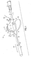
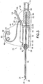
- FIG. 13 is a perspective view of a needle device in accordance with yet a further embodiment.
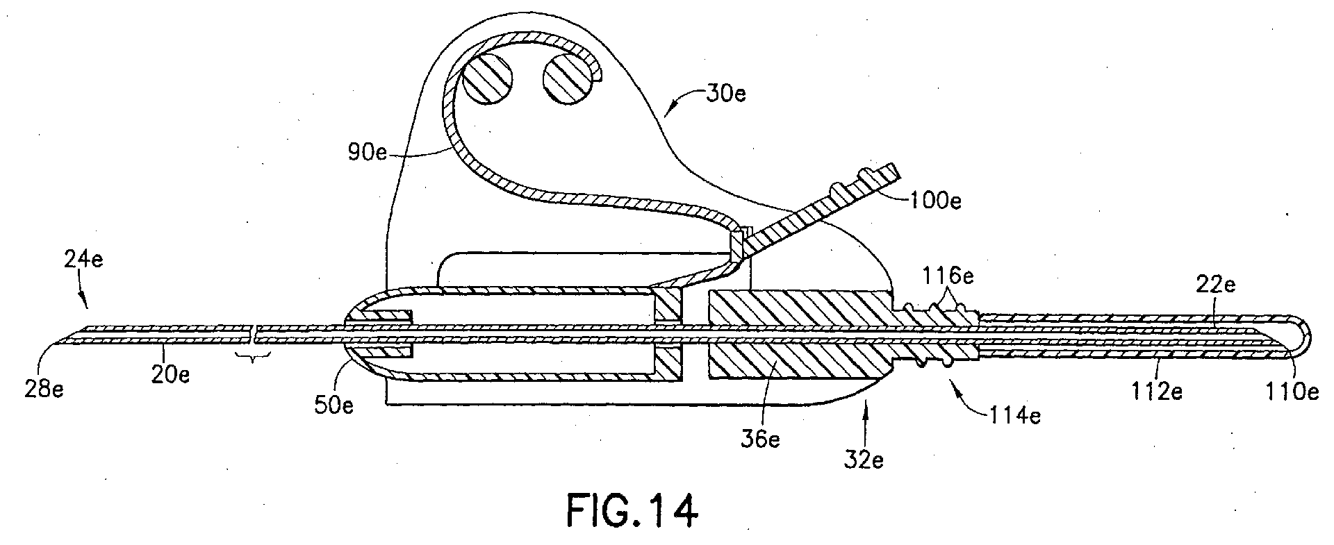
- FIG. 14 is a side cross-sectional view of the needle device of FIG. 13.
- FIG. 1 illustrates a blood collection set in the form of a wingset including a shieldable needle device, in accordance with the present invention and the related features.
- the present invention is generally described in terms of a shieldable needle device.
- FIG. 1 illustrates the shieldable needle device in the form of a blood collection set 10 including a shieldable needle device 12 .
- the shieldable needle device of the present invention may be used with or incorporate other medical devices used in connection with a needle, such as a hypodermic syringe assembly, a hypodermic needle, a double-ended needle assembly for blood collection, an intravenous infusion set, or other handling devices or medical device assemblies that contain piercing elements.
- blood collection set 10 includes a shieldable needle device 12 , a flexible tube 14 extending from needle device 12 , a fixture 16 mounted to tube 14, and a packaging cover 18 removably mounted to portions of needle device 12 opposite tube 14, such as through frictional engagement.
- Shieldable needle device 12 of blood collection set 10 is shown in detail in FIGS. 2 and 3 and includes a needle cannula 20 , a housing 30 , a tip guard assembly 50 and a flexibly resilient drive mechanism 90 .
- Needle cannula 20 includes a rearward end or proximal end 22 and a forward end or opposing distal end 24 , with lumen 26 extending through needle cannula 20 from proximal end 22 to distal end 24 .
- Distal end 24 of needle cannula 20 is beveled to define a sharp puncture tip 28 , such as an intravenous puncture tip. Puncture tip 28 is provided for insertion into a patient's blood vessel, such as a vein, and is therefore designed to provide ease of insertion and minimal discomfort during venipuncture.
- Needle device 12 further includes housing 30 .
- Housing 30 is a unitary structure, desirably molded from a thermoplastic material.
- Housing 30 generally includes a rearward end or proximal end 32 , and an opposing forward end or distal end 34.
- a hub 36 is providing at proximal end 32 of housing 30, with an internal passageway 38 extending therethrough.
- Hub 36 is desirably a generally tubular-shaped structure.
- First lateral extension 40 and second lateral extension 42 extend from opposing lateral sides of hub 36 , generally in an upward manner, toward distal end 34 of housing 30 , thereby forming a dorsal fin-shaped structure.
- First lateral extension 40 and second lateral extension 42 are spaced from each other, and are preferably planar structures that are parallelly-spaced.
- first lateral extension 40 and second lateral extension 42 are interconnected to each other through a connector 44 , which is located within the dorsal fin-shaped structure of the lateral extensions.
- An additional connector 46 may also be provided, as shown in FIGS. 3 and 4, which provides additional structural integrity and provides for mounting of the drive mechanism, which will be discussed in more detail herein.
- Housing 30 may further include a first lateral wing 130 extending from the first lateral extension 40 , and a second lateral wing 132 extending from the second lateral extension 42 .
- first lateral wing 130 and second lateral wing 132 extend from first lateral extension 40 and second lateral extension 42 , respectively, at an angle of about 90°.
- First lateral wing 130 and second lateral wing 132 provide housing 30 and needle device 12 as a butterfly-type wingset assembly with a pair of generally planar wings extending from opposing sides for assisting in positioning and placement of needle device and blood collection set 10 during blood collection procedures.
- first lateral wing 130 and second lateral wing 132 are generally planar or flat, which provides an effective surface to lie against the skin of a patient during use.
- First cutaway portion 134 may be provided between first lateral wing 130 and first lateral extension 40
- second cutaway portion 136 may be provided between second lateral wing 132 and second lateral extension 42 .
- Needle cannula 20 is positioned within internal passageway 38 of hub 36 of housing 30 , and extends from forward end 34 of housing 30 .
- needle cannula 20 and housing 30 are separate parts which are fixedly attached and secured through an appropriate medical grade adhesive or the like.
- Housing 30 may further include a nub 48 extending from the rearward or proximal end 32 for attachment with flexible tube 14.
- Needle device 12 further includes tip guard assembly 50, which is movable along needle cannula 20 between a first rearward or retracted position adjacent housing 30 , and a second forward or extended position adjacent puncture tip 28 , as will be described in more detail herein.
- the tip guard assembly 50 may be any assembly capable of telescoping along needle cannula 20 to a position shielding the tip of the needle.
- the tip guard assembly 50 may be of a unitary, one-piece construction, or may be of a two-piece construction.
- Tip guard assembly 50 includes a housing 52 , which is a unitary structure, desirably molded from a thermoplastic material, including a rearward or proximal end 54 , a forward or distal end 56 , and an internal passage 58 extending between a proximal opening 60 and a distal opening 62 .
- Distal end 56 includes an annular wall 64 extending within internal passage 58 from proximal end 54 .
- Annular wall 64 creates a distal pocket 66 extending annularly around annular wall 64 at distal end 56.
- tip guard assembly 50 In a retracted position, tip guard assembly 50 is positioned along needle cannula 20 between first lateral extension 40 and second lateral extension 42 of housing 30 adjacent distal end 34 . Proximal end 54 of tip guard assembly 50 may abut hub 36 of housing 30 , or may be spaced therefrom.
- Drive mechanism 90 provides for activation of the safety shielding feature of shieldable needle device 12 through axial movement of tip guard assembly 50 along needle cannula 20 from the retracted position within housing 30 to an extended position adjacent puncture tip 28 , as will be described in more detail herein.
- Drive mechanism 90 is an elongated flexibly resilient structure.
- “flexibly resilient” refers to a structure which is able to bend easily, and which is able to easily resume its original shape after bending.
- Drive mechanism 90 may be constructed of any material capable of providing such properties, and is desirably constructed of a polymeric or metallic material.
- drive mechanism 90 may include any profile, such as a round, wire-like profile, or a ribbon-like profile.
- drive mechanism 90 is a leaf spring, which is in a biased state when retained in a bent position and automatically resumes its original shape when released.
- Drive mechanism 90 includes a first end 92 and a second end 94.
- First end 92 is anchored to housing 30, such as through an attachment with connector 44 between first lateral extension 40 and second lateral extension 42 at a point between the dorsal fin-shaped structure. Such an attachment may be provided through an appropriate medical grade adhesive or the like.
- Drive mechanism 90 extends from first end 92 to second end 94 at a location between first lateral extension 40 and second lateral extension 42 .
- drive mechanism 90 extends from the first end 92 attached to connector 44 in a direction toward distal end 34 of housing 30 , and is bent rearwardly toward proximal end 32 of housing 30 , such as around a second connector 46 .
- Such bent structure provides drive mechanism 90 with a biasing force, due to the flexible resilient nature of drive mechanism 90 .
- the second end 94 of drive mechanism 90 is attached to tip guard assembly 50, desirably at proximal end 54 thereof.
- Drive mechanism 90 is of a sufficient length to fully extend when tip guard assembly 50 is in an extended position encompassing the distal end 24 of needle cannula 20.
- Drive mechanism 90 further includes a mechanism for retaining drive mechanism 90 in a biased state between first lateral extension 40 and second lateral extension 42 when tip guard assembly 50 is in the retracted position.
- a lockout lug 96 is desirably provided adjacent second end 94 of drive mechanism 90 .
- Lockout lug 96 includes an edge portion 98 which provides for abutting engagement with a portion of housing 30 for retaining drive mechanism 90 in a biased state, such as in a bent or coiled state, when tip guard assembly 50 is in the retracted position.
- housing 30 may include first cutaway portion 134 and second cutaway portion 136 , providing between first lateral wing 130 and first lateral extension 40 and second lateral wing 132 and second lateral extension 42 , respectively.
- first cutaway portion 134 and second cutaway portion 136 may include profile for frictional engagement with lockout lug 96 , such as a notch 138 , as shown in FIGS. 2 and 3.
- Edge portion 98 of lockout lug 96 abuts the edge surface of notch 138 , thereby maintaining drive mechanism 90 in a biased state.
- First and second cutaway portions 134, 136 further provide a means for lockout lug 96 to pass through housing 30 when tip guard assembly 50 is propelled from the retracted position to the extended position through the biasing force of drive mechanism 90 , as will be discussed in more detail herein.
- housing 30 may include interior passages or channels on opposing internal surfaces thereof, acting in a similar manner as first and second cutaway portions 134, 136 for permitting lockout lug 96 to pass through housing 30 during such movement.
- Second end 94 of drive mechanism 90 may further include a release latch 100 , for releasing lockout lug 96 from abutting engagement with notch 138 .
- Release latch 100 may be an extension portion which is integrally formed with or separately attached to drive mechanism 90 .
- release latch 100 may extend from tip guard assembly 50 as a portion which is integrally formed therewith or separately attached thereto. With such an arrangement, second end 94 of drive mechanism 90 may be attached to release latch 100 , providing for ease of release of locking lug 96 from notch 138 .
- Release latch 100 desirably includes a surface having a profile for accommodating a user's finger, such as ribs or bumps 102.
- Blood collection set 10 can be packaged substantially in the condition shown in FIG. 1, with drive mechanism 90 in a biased state. Prior to use, blood collection set 10 is removed from its package. Fixture 16 may then be connected to an appropriate receptacle for providing fluid communication with lumen 26 through needle cannula 20 .
- blood collection set 10 is provided with needle device 12 assembled and including flexible tube 14 extending from needle device 12 and connected to fixture 16 . After removing blood collection set 10 from its package, it can be assembled with other appropriate medical equipment for use. For example, a non-patient needle assembly and a needle holder may be connected to blood collection set 10 through fixture 16 .
- blood collection set 10 To prepare for use of blood collection set 10 , the user grasps blood collection set 10 at needle device 12, with first lateral extension 40 and second lateral entension 42 acting as a surface for grasping between a user's finger and thumb. Packaging cover 18 is then grasped and urged distally in a direction of arrow 150 to disengage from needle cannula 20 , thereby exposing puncture tip 28 of needle cannula 20 .
- the medical practitioner can then urge puncture tip 28 at distal end 24 of needle cannula 20 into a targeted blood vessel of a patient.
- First and second lateral wings 130, 132 are maintained flush against the patient's skin during such procedure, thereby ensuring that needle device 12 is inserted in the proper orientation within the vessel.
- needle cannula 20 is withdrawn from the patient, and activation of the safety feature of needle device 12 can be accomplished.
- release latch 100 is activated by exerting downward pressure in a direction of arrow 152 .
- Such force causes lockout lug 96 to become disengaged from notch 138 , thereby eliminating the abutting relationship of edge portion 98 of lockout lug 96 within notch 138 .
- drive mechanism 90 Prior to being released, drive mechanism 90 is bent as shown in FIG. 3, and is therefore in a biased state. After release of lockout lug 96 from notch 138 , drive mechanism 90 is free to exert a biasing force. Such release of drive mechanism 90 from its retained position causes it to unbend due to the flexibly resilient nature of drive mechanism 90 .
- second end 94 of drive mechanism 90 is fixedly attached to tip guard assembly 50 , and since tip guard assembly 50 is axially movable along needle cannula 20 , such movement and unbending creates a biasing force between drive mechanism 90 and tip guard assembly 50 , which causes tip guard assembly 50 to axially move away from housing 30 toward distal end 24 of needle cannula 20 such that it slides or glides along needle cannula 20 toward distal end 24 due to the biasing force of drive mechanism 90 .
- lockout lug 96 passes through housing 30 at first cutaway portion 134 and second cutaway portion 136 .
- tip guard assembly 50 After tip guard assembly 50 is moved along needle cannula 20 to the distal end 24 , puncture tip 28 of needle cannula 20 passes entirely through the distal opening 62 within distal end 56 and into the internal passage 58 .
- the biasing force of drive mechanism 90 causes tip guard assembly 50 to then be slightly offset from its longitudinal axis, thereby causing puncture tip 28 to be trapped within distal pocket 66 between housing 52 and annular wall 64 , as shown in FIG. 4 Thus, a return movement of tip guard assembly 50 is prevented.
- drive mechanism 90 has a length that will prevent movement of tip guard assembly 50 distally beyond needle cannula 20 . Hence, puncture tip 28 of needle cannula 20 is safely shielded. Blood collection set 10 may then be appropriately discarded.
- activation of the safety feature may be accomplished while venipuncture is maintained, that is while puncture tip 28 of needle cannula 20 is maintained within the blood vessel of the patient.
- release latch 100 can be activated while puncture tip 28 is within the patient's blood vessel, thereby axially moving tip guard assembly 50 axially along needle cannula 20 . Since puncture tip 28 is within the patient's blood vessel, such distal movement of tip guard assembly 50 will terminate when housing 52 of tip guard assembly 50 contacts the skin of the patient near the puncture site. Upon removal of puncture tip 28 from the patient's blood vessel, tip guard assembly 50 will continue in its axial movement toward the distal end 24 of needle cannula 20 due to the bias exerted through drive mechanism 90 . Such axial movement results in tip guard assembly 50 shielding puncture tip 28 of needle cannula 20 .
- FIGS. 5-14 depict further embodiments of the present invention that include many components which are substantially identical to the components of FIGS. 1-4. Accordingly, similar components performing similar functions will be numbered identically to those components of FIGS. 1-4, except that a suffix "a” will be used to identify those similar components in FIGS. 5 and 6, a suffix "b” will be used to identify those similar components in FIGS. 7 and 8, a suffix "c” will be used to identify those similar components in FIGS. 9 and 10, a suffix “d” will be used to identify those similar components in FIGS. 11 and 12, and a suffix "e” will be used to identify those similar components in FIGS. 13 and 14.
- needle device 12a works in a similar manner as the device described in connection with the embodiment of FIGS. 1-4, with the exception that drive mechanism 90a is coiled as a wound spring as opposed to being bent around a bend as a leaf spring.
- drive mechanism 90a is coiled as a wound spring as opposed to being bent around a bend as a leaf spring.
- first end 92a is connected to connector 44a with drive mechanism 90a wound about connector 44a , thereby creating energy within drive mechanism 90a for establishing a biasing force against tip guard assembly 50a attached at second end 94a .
- drive mechanism 90a When release latch 100a is released, drive mechanism 90a unwinds and becomes uncoiled, thereby releasing it's energy and forcing tip guard assembly 50a to a shielding or extended position about puncture tip 28a .
- only a single point of connection is desirably provided between the first and second lateral extensions of housing 30a , such as at connector 44a .
- a bushing 140a is desirably provided about connector 44a, as a point of attachment between drive mechanism 90a and housing 30a, with bushing 140a permitting unwinding of drive mechanism 90a around connector 44a.
- tip guard assembly 50b is provided as a one-piece assembly including a rearward or proximal end 54b and a forward or distal end 56b , with top extent 68b defining the top portion of tip guard assembly 50b for extending longitudinally along a portion of the needle cannula between proximal end 54b and distal end 56b .
- Top extent 68b bends downwardly at distal end 56b to form front end wall 70b .
- spring leg 78b which extends back toward the distal end 56b of tip guard assembly 50b , with lockout leg 84b bending upward and backward to form an end wall, as seen in FIG.
- Proximal end 54b of tip guard assembly 50b includes proximal opening 60b, while distal end 56b of tip guard assembly 50b includes distal opening 62b extending through front end wall 70b.
- Proximal opening 60b and distal opening 62b are provided for accommodating the needle cannula extending therethrough.
- the bends in lockout leg 84b enable secure protective engagement with puncture tip 28b of the needle cannula and further enable smooth axial sliding movement of tip guard assembly 50b along the needle cannula.
- FIGS. 9 and 10 depict a further tip guard assembly 50c for use in connection with the present invention, in the form of a two-piece assembly.
- tip guard assembly 50c includes housing 52c having a proximal end 54c and a distal end 56c, with a portion of internal passage 58c adjacent distal end 56c defining an enlarged clip receptacle 74c.
- a clip mounting post 76c extends downwardly from housing 52c at a location near proximal end 54c of housing 52c.
- a clip 72c is unitarily stamped and formed from a resiliently deflectable metallic material.
- Clip 72c includes a planar spring leg 78c with a proximal end 80c and an opposed distal end 82c.
- a mounting aperture 86c extends through spring leg 78c at a location near proximal end 80c.
- the mounting aperture has a diameter approximately equal to or slightly less than the diameter of mounting post 76c of housing 52c. As such, mounting post 76c can be forced through the mounting aperture when the axis of mounting post 76c and the axis of mounting aperture 86c are substantially co-linear.
- a lockout leg 84c extends angularly from distal end 82c of spring leg 78c.
- Lockout leg 84c is bent back toward proximal end 80c of clip 72c. The bends in lockout leg 84c enable secure protective engagement with puncture tip 28c of needle cannula 20c and further enable smooth axial sliding movement of tip guard assembly 50c along needle cannula 20c.
- needle assembly of the present invention has been described in terms of an embodiment for use in connection with a blood collection system, it is further contemplated that the needle assembly could be used with other medical procedures, such as in conjunction with a conventional intravenous infusion set, a hypodermic needle assembly, or a double ended needle assembly for blood collection, all of which are well-known in the art for use with needle devices.
- FIGS. 11 and 12 depict safety needle device 12d for attachment to conventional medical devices, such as conventional needle holders for blood collection, syringes, and the like.
- the safety needle device 12 includes a needle cannula 20 , a housing 30 , and a tip guard assembly 50 , as set forth in the embodiment described above.
- the safety needle device 12d is an independent component for attachment to a medical device, such as a hypodermic syringe.
- housing 30d acts as a base housing for providing such attachment.
- housing 30d includes means for attachment with a medical device, such as a hypodermic syringe, at proximal end 32d .
- a medical device such as a hypodermic syringe
- housing 30d may include a threaded end at the proximal end 32d thereof.
- housing 30d includes a female luer fitting 104d and a luer flange 106d at the proximal end thereof.
- Female luer fitting 104d includes an inner tapered surface 108d .
- Such an arrangement provides for attachment with a luer collar, such as a syringe luer collar.
- Such a luer fitting enables safety needle device 12d to be sold as a sterile needle device for use with a conventional medical device adapted for use with a luer fitting. Since the safety needle device 12d of FIGS. 11 and 12 is intended for use with a syringe or the like, first and second lateral wings 130 and 132 , such as those shown in FIGS. 1 and 2, are not necessarily provided.
- safety needle device 12e is provided as an independent component in the form of a double-ended needle assembly for attachment to a needle holder, as is known for use in connection with blood sampling procedures.
- needle cannula 20e is in the form of double-ended needle, including puncture tip 28e as an intravenous puncture tip at distal end 24e thereof, and a non-patient puncture tip 110e at proximal end 22e thereof.
- Needle cannula 20e extends through hub 36e of housing 30e.
- Proximal end 22e of needle cannula 20e desirably includes an elastomeric sleeve 112e covering non-patient puncture tip 110e.
- Housing 30e desirably includes means for attachment to a separate needle holder (not shown).
- housing 30e may include a threaded end 114e at the proximal end 32e thereof.
- threaded end 114e comprises male threads 116e for mounting needle device 12e on a standard needle holder.
- needle device 12e is desirably packaged as shown in FIG. 13, including packaging cover 18e covering distal end 24e of needle cannula 20e , and further including a second packaging cover 120e covering proximal end 22e of needle cannula 20e .
Abstract
Description
Claims (16)
- A shieldable needle device comprising:a housing including a first lateral extension and a second lateral extension, said first lateral extension and said second lateral extension interconnected at a rearward end of said housing forming a hub portion;a needle cannula including a forward end and a rearward end, said needle cannula extending from said hub portion of said housing;a tip guard axially movable along said needle cannula between a retracted position where said forward end of said needle cannula is exposed and an extended position where said tip guard protectively surrounds said forward end of said needle cannula; anda flexibly resilient drive mechanism for biasing said tip guard to said extended position including a first end anchored to said housing between said first lateral extension and said second lateral extension, and a second end anchored to said tip guard, said drive mechanism capable of being retained in a biased state between said first lateral extension and said second lateral extension when said tip guard is in said retracted position.
- A shieldable needle device as in claim 1, wherein said drive mechanism comprises a leaf spring.
- A shieldable needle device as in claim 1, wherein said drive mechanism comprises a coiled spring wound between said first lateral extension and said second lateral extension.
- A shieldable needle device as in claim 1, wherein said drive mechanism includes a locking lug adjacent said second end thereof, said locking lug capable of frictional engagement with said housing for retaining said drive mechanism in a biased state between said first lateral extension and said second lateral extension when said tip guard is in said retracted position.
- A shieldable needle device as in claim 4, further comprising a release latch for releasing said locking lug from frictional engagement with said housing, thereby causing said drive mechanism to bias said tip guard to said extended position.
- A shieldable needle device as in claim 5, wherein said release latch includes a surface having a profile for accommodating a user's finger.
- A shieldable needle device as in claim 5, wherein said release latch extends from said tip guard, and said drive mechanism is attached to said release latch at said locking lug.
- A shieldable needle device as in claim 1, wherein said first lateral extension of said housing includes a first lateral wing and said second lateral extension of said housing includes a second lateral wing, said first lateral wing and said second lateral wing forming a pair of generally planar wings extending from opposing sides of said housing.
- A shieldable needle device as in claim 1, wherein said housing is adapted for connection to a blood collection set.
- A shieldable needle device as in claim 1, wherein said housing further includes means for attachment with a hypodermic syringe.
- A shieldable needle device as in claim 1, including a packaging cover extending over said needle cannula.
- A shieldable needle wingset for blood collection comprising:a fixture for connecting the wingset to a receptacle;a flexible tube having opposed first and second ends, said first end of said flexible tube being connected to said fixture;a wingset housing mounted to said second end of said flexible tube, said wingset housing including a first lateral section having a first lateral wing and a first dorsal fin, and a second lateral section having a second lateral wing and a second dorsal fin, said first lateral section and said second lateral section interconnected at a rearward end of said wingset housing forming a hub portion;a needle cannula including a forward end and a rearward end, said needle cannula extending from said hub portion of said wingset housing;a tip guard axially movable along said needle cannula between a retracted position where said forward end of said needle cannula is exposed and an extended position where said tip guard protectively surrounds said forward end of said needle cannula; anda leaf spring for biasing said tip guard to said extended position including a first end anchored to said wingset housing between said first dorsal fin and said second dorsal fin, and a second end anchored to said tip guard, said leaf spring capable of being retained in a biased state between said first dorsal fin and said second dorsal fin when said tip guard is in said retracted position.
- A shieldable needle wingset as in claim 12, wherein said leaf spring is wound into a coiled spring about a bar extending between said first lateral extension and said second lateral extension.
- A shieldable needle wingset as in claim 12, wherein said leaf spring includes a locking lug adjacent said second end thereof, said locking lug capable of frictional engagement with said housing for retaining said leaf spring in a biased state between said first dorsal fin and said second dorsal fin when said tip guard is in said retracted position.
- A shieldable needle wingset as in claim 14, further comprising a release latch for releasing said locking lug from frictional engagement with said housing, thereby causing said leaf spring to bias said tip guard to said extended position.
- A shieldable needle wingset as in claim 15, wherein said release latch includes a surface having a profile for accommodating a user's finger.
Priority Applications (1)
| Application Number | Priority Date | Filing Date | Title |
|---|---|---|---|
| EP10178727.3A EP2266462B1 (en) | 2002-12-19 | 2003-12-17 | Shieldable needle device with leaf spring driven shield |
Applications Claiming Priority (2)
| Application Number | Priority Date | Filing Date | Title |
|---|---|---|---|
| US43563402P | 2002-12-19 | 2002-12-19 | |
| US435634P | 2002-12-19 |
Related Child Applications (2)
| Application Number | Title | Priority Date | Filing Date |
|---|---|---|---|
| EP10178727.3A Division EP2266462B1 (en) | 2002-12-19 | 2003-12-17 | Shieldable needle device with leaf spring driven shield |
| EP10178727.3 Division-Into | 2010-09-23 |
Publications (3)
| Publication Number | Publication Date |
|---|---|
| EP1430834A2 true EP1430834A2 (en) | 2004-06-23 |
| EP1430834A3 EP1430834A3 (en) | 2005-11-30 |
| EP1430834B1 EP1430834B1 (en) | 2013-02-20 |
Family
ID=32393631
Family Applications (2)
| Application Number | Title | Priority Date | Filing Date |
|---|---|---|---|
| EP03078951A Expired - Lifetime EP1430834B1 (en) | 2002-12-19 | 2003-12-17 | Shieldable needle device with leaf spring driven shield |
| EP10178727.3A Expired - Lifetime EP2266462B1 (en) | 2002-12-19 | 2003-12-17 | Shieldable needle device with leaf spring driven shield |
Family Applications After (1)
| Application Number | Title | Priority Date | Filing Date |
|---|---|---|---|
| EP10178727.3A Expired - Lifetime EP2266462B1 (en) | 2002-12-19 | 2003-12-17 | Shieldable needle device with leaf spring driven shield |
Country Status (6)
| Country | Link |
|---|---|
| US (1) | US7422573B2 (en) |
| EP (2) | EP1430834B1 (en) |
| JP (1) | JP4464124B2 (en) |
| CN (1) | CN1309346C (en) |
| BR (1) | BR0306073A (en) |
| ES (2) | ES2611493T3 (en) |
Cited By (7)
| Publication number | Priority date | Publication date | Assignee | Title |
|---|---|---|---|---|
| EP1632179A1 (en) * | 2004-09-02 | 2006-03-08 | Nipro Corporation | Lancet with needle protector |
| WO2014077831A1 (en) * | 2012-11-15 | 2014-05-22 | Becton, Dickinson And Company | Passive double drive member activated safety blood collection device |
| CN104665844A (en) * | 2013-11-27 | 2015-06-03 | 周文正 | Painless lancet |
| US9456775B2 (en) | 2013-09-06 | 2016-10-04 | Millaghi Medical, Inc. | Passive safety I.V. blood collection catheter |
| US9861784B2 (en) | 2013-12-03 | 2018-01-09 | Becton, Dickinson And Company | Blood collection device with double pivot shields |
| WO2021001450A1 (en) * | 2019-07-02 | 2021-01-07 | B. Braun Melsungen Ag | Blood collectable peripheral intravenous catheter assemblies and related methods |
| WO2022250536A1 (en) * | 2021-05-25 | 2022-12-01 | Crea Ip B.V. | Cannula tip protector |
Families Citing this family (24)
| Publication number | Priority date | Publication date | Assignee | Title |
|---|---|---|---|---|
| US20070016226A1 (en) * | 2005-07-13 | 2007-01-18 | Bio Medic Data Systems, Inc. | Implanter |
| JP4994775B2 (en) | 2006-10-12 | 2012-08-08 | 日本コヴィディエン株式会社 | Needle point protector |
| US8439870B2 (en) | 2008-09-10 | 2013-05-14 | B. Braun Medical Inc. | Safety needle assembly and methods |
| US8512295B2 (en) | 2010-08-19 | 2013-08-20 | West Pharmaceutical Services, Inc. | Rigid needle shield |
| USD666711S1 (en) * | 2011-01-17 | 2012-09-04 | Poly Medicure Limited | Safety needle clip |
| US9238104B2 (en) | 2011-02-28 | 2016-01-19 | Injectimed, Inc. | Needle guard |
| US8764711B2 (en) | 2011-02-28 | 2014-07-01 | Injectimed, Inc. | Needle guard |
| US8486024B2 (en) | 2011-04-27 | 2013-07-16 | Covidien Lp | Safety IV catheter assemblies |
| WO2012170805A2 (en) * | 2011-06-09 | 2012-12-13 | Knee Creations, Llc | Instruments and devices for subchondral joint repair |
| WO2013048768A1 (en) | 2011-09-26 | 2013-04-04 | Covidien Lp | Safety iv catheter and needle assembly |
| EP2760520A1 (en) | 2011-09-26 | 2014-08-06 | Covidien LP | Safety catheter |
| WO2013056223A1 (en) | 2011-10-14 | 2013-04-18 | Covidien Lp | Safety iv catheter assembly |
| ES2779624T3 (en) | 2011-11-07 | 2020-08-18 | Safety Syringes Inc | Needle guard with contact trigger activation |
| WO2013134508A1 (en) * | 2012-03-07 | 2013-09-12 | Medical Components, Inc. | Huber needle assembly |
| WO2014121119A1 (en) | 2013-02-01 | 2014-08-07 | Nxstage Medical, Inc. | Safe cannulation devices, methods, and systems |
| CU24259B1 (en) | 2013-10-10 | 2017-06-05 | Medical Components Inc | HUBER NEEDLE ASSEMBLY WITH SAFETY CAPTURE DEVICE |
| BR112017003765B1 (en) | 2014-08-29 | 2022-05-17 | Medical Components, Inc | Huber safety needle set |
| USD804022S1 (en) | 2015-02-27 | 2017-11-28 | Medical Components, Inc. | Huber safety needle |
| USD804021S1 (en) | 2015-02-27 | 2017-11-28 | Medical Components, Inc. | Huber safety needle |
| ITUB20159438A1 (en) * | 2015-12-23 | 2017-06-23 | Bnp S R L | SINGLE-USE SAFETY BUTTERFLY NEEDLE |
| EP3429661A1 (en) * | 2016-03-18 | 2019-01-23 | Medical Components, Inc. | Huber safety needle |
| USD828653S1 (en) * | 2016-12-14 | 2018-09-11 | Brandon Penland | Treatment applicator |
| US10569069B2 (en) | 2016-12-14 | 2020-02-25 | Combat Comb, Llc | Applicator for treatments applied to animal skin |
| IT202000017761A1 (en) | 2020-07-22 | 2022-01-22 | Bnp S R L | DISPOSABLE SAFETY BUTTERFLY NEEDLE |
Citations (3)
| Publication number | Priority date | Publication date | Assignee | Title |
|---|---|---|---|---|
| US4892521A (en) | 1988-08-03 | 1990-01-09 | Lincoln Mills, Inc. | Protective cover for hypodermic needle |
| US5423766A (en) | 1994-08-26 | 1995-06-13 | Becton, Dickinson And Company | Safety shield having spring tether |
| EP1132103A1 (en) | 2000-03-07 | 2001-09-12 | Becton Dickinson and Company | Passive safety device |
Family Cites Families (56)
| Publication number | Priority date | Publication date | Assignee | Title |
|---|---|---|---|---|
| US2725058A (en) * | 1952-12-29 | 1955-11-29 | Arthur S Rathkey | Intravenous needle |
| US4139009A (en) * | 1976-11-23 | 1979-02-13 | Marcial Alvarez | Hypodermic needle assembly with retractable needle cover |
| US4735618A (en) * | 1987-07-20 | 1988-04-05 | Henry E. Szachowicz, Jr. | Protective enclosure for hypodermic syringe |
| US4867746A (en) * | 1988-05-23 | 1989-09-19 | Becton, Dickinson And Company | Needle shield |
| US4909794A (en) * | 1988-06-24 | 1990-03-20 | Habley Medical Technology Corporation | Combination retractable needle cannula and cannula lock for a medication carpule |
| US4911706A (en) * | 1988-10-14 | 1990-03-27 | Regents Of The University Of Minnesota | Automatic needle cover |
| US4998922A (en) * | 1990-02-23 | 1991-03-12 | Kuracina Thomas C | Safety syringe cap minimizing needle-stick probability |
| US5067946A (en) * | 1990-04-10 | 1991-11-26 | Semen Zhadanov | Injury resistant needle device |
| US5558651A (en) * | 1990-04-20 | 1996-09-24 | Becton Dickinson And Company | Apparatus and method for a needle tip cover |
| US5059184A (en) * | 1990-05-03 | 1991-10-22 | Dyke Timothy J | Hypodermic needle apparatus |
| US5051109A (en) * | 1990-07-16 | 1991-09-24 | Simon Alexander Z | Protector for catheter needle |
| US5176655A (en) * | 1990-11-08 | 1993-01-05 | Mbo Laboratories, Inc. | Disposable medical needle and catheter placement assembly having full safety enclosure means |
| US5108376A (en) * | 1990-11-14 | 1992-04-28 | Safetyject | Retractable intravenous needle assembly |
| US5152751A (en) * | 1990-12-04 | 1992-10-06 | Kozlowski David J | Hypodermic needle safety shield |
| US5256152A (en) * | 1991-10-29 | 1993-10-26 | Marks Lloyd A | Safety needle and method of using same |
| US5215534A (en) * | 1991-12-02 | 1993-06-01 | Lawrence De Harde | Safety syringe system |
| US5242418A (en) * | 1992-05-22 | 1993-09-07 | Weinstein James D | Protective means for a needle or similar cannula medical device |
| US5538508A (en) * | 1992-07-31 | 1996-07-23 | Steyn; Ricardo S. | Needle protective device |
| US5295972A (en) * | 1992-08-04 | 1994-03-22 | Metatech Corporation | Hypodermic syringe with protective cap |
| US5250031A (en) * | 1992-12-14 | 1993-10-05 | The George Washington University | Locking needle cover |
| US5425720A (en) * | 1993-01-27 | 1995-06-20 | Rogalsky; Alena | Medical needle unit |
| US5549570A (en) * | 1993-01-27 | 1996-08-27 | Rogalsky; Alena | Medical needle unit |
| US5348544A (en) * | 1993-11-24 | 1994-09-20 | Becton, Dickinson And Company | Single-handedly actuatable safety shield for needles |
| US5334158A (en) * | 1993-12-20 | 1994-08-02 | Mclees Donald J | Automatic needle tip guard for standard hypodermic needles |
| US5746718A (en) * | 1994-07-05 | 1998-05-05 | Steyn; Ricardo Sheath Oxford | Needle protective device |
| US5584818A (en) * | 1994-08-22 | 1996-12-17 | Morrison; David | Safety hypodermic needle and shielding cap assembly |
| US5925020A (en) * | 1994-11-22 | 1999-07-20 | Becton, Dickinson And Company | Needle point barrier |
| CA2168615A1 (en) * | 1995-03-07 | 1996-09-08 | Timothy J. Erskine | Catheter-advancement actuated needle retraction system |
| US5569202A (en) * | 1995-06-07 | 1996-10-29 | Johnson & Johnson Medical, Inc. | Catheter needle tip protector |
| US5746215A (en) * | 1996-11-01 | 1998-05-05 | U.S. Medical Instruments, Inc. | IV infusion or collection device with extendable and retractable needle |
| US5779679A (en) * | 1997-04-18 | 1998-07-14 | Shaw; Thomas J. | Winged IV set with retractable needle |
| US5810784A (en) * | 1997-08-15 | 1998-09-22 | Tamaro; Frank A. | Safety cap assembly for needles and catheters |
| US6117108A (en) * | 1997-08-20 | 2000-09-12 | Braun Melsungen Ag | Spring clip safety IV catheter |
| US5919168A (en) | 1997-08-25 | 1999-07-06 | Wheeler; Alton D. | Injection needle protection |
| US5910132A (en) * | 1998-01-06 | 1999-06-08 | B. Braun Medical Inc. | Safety IV catheter guard |
| US5951525A (en) * | 1998-02-10 | 1999-09-14 | Specialized Health Products, Inc. | Manual safety medical needle apparatus and methods |
| US5951522A (en) * | 1998-11-05 | 1999-09-14 | Millennium Medical Distribution | Hypodermic needle safety enclosure |
| US6210371B1 (en) * | 1999-03-30 | 2001-04-03 | Retractable Technologies, Inc. | Winged I.V. set |
| JP2002191695A (en) * | 2000-10-20 | 2002-07-09 | Mitsubishi Pencil Co Ltd | Needle tip part cover member, assembly method of injection needle with needle tip part cover member, injection needle with needle guard member and syringe with needle guard member |
| US20020120215A1 (en) * | 2001-01-05 | 2002-08-29 | Crawford Jamieson William Maclean | Blood collection set with retractable needle |
| US6855127B2 (en) * | 2001-01-25 | 2005-02-15 | Nipro Corporation | Needle assembly |
| CN101390768A (en) * | 2001-12-28 | 2009-03-25 | 贝克顿迪肯森公司 | Medical needle assemblies |
| CN1269537C (en) * | 2002-03-19 | 2006-08-16 | 贝克顿迪肯森公司 | Needle assembly |
| US6926700B2 (en) * | 2002-03-19 | 2005-08-09 | Becton, Dickinson And Company | Needle assembly |
| AU2003201336A1 (en) * | 2002-03-19 | 2003-10-16 | Becton, Dickinson And Company | Needle assembly |
| CA2422516A1 (en) * | 2002-03-19 | 2003-09-19 | Becton, Dickinson And Company | Needle device |
| AU2003201341A1 (en) * | 2002-03-20 | 2003-10-16 | Becton, Dickinson And Company | Needle assembly |
| CA2422307A1 (en) | 2002-03-20 | 2003-09-20 | Stefanie Livanos | Blood collection device |
| DE60300692T2 (en) * | 2002-03-21 | 2006-05-04 | Becton Dickinson And Co. | Needle safety device with a wing |
| US6835190B2 (en) * | 2002-04-17 | 2004-12-28 | Smiths Medical Asd, Inc. | Retractable safety infusion needle |
| DE60303415T2 (en) | 2002-05-15 | 2006-08-24 | Becton Dickinson And Co. | Needle protector |
| US7018344B2 (en) * | 2003-01-21 | 2006-03-28 | Becton, Dickinson And Company | Retractable needle shielding device |
| US7041066B2 (en) * | 2003-03-13 | 2006-05-09 | Becton, Dickinson & Company | Needle assembly |
| US7144388B2 (en) * | 2003-12-01 | 2006-12-05 | Becton Dickinson And Company | Selectively passive shieldable medical needle device |
| US7150725B2 (en) * | 2003-12-17 | 2006-12-19 | Becton Dickinson And Company | Passive activated safety blood collection set |
| US20070100296A1 (en) * | 2005-10-31 | 2007-05-03 | Becton, Dickinson And Company | Single-handedly actuatable shield for needles |
-
2003
- 2003-12-15 US US10/736,213 patent/US7422573B2/en active Active
- 2003-12-17 EP EP03078951A patent/EP1430834B1/en not_active Expired - Lifetime
- 2003-12-17 ES ES10178727.3T patent/ES2611493T3/en not_active Expired - Lifetime
- 2003-12-17 ES ES03078951T patent/ES2407356T3/en not_active Expired - Lifetime
- 2003-12-17 EP EP10178727.3A patent/EP2266462B1/en not_active Expired - Lifetime
- 2003-12-18 JP JP2003421642A patent/JP4464124B2/en not_active Expired - Lifetime
- 2003-12-19 BR BR0306073-0A patent/BR0306073A/en not_active IP Right Cessation
- 2003-12-19 CN CNB2003101239026A patent/CN1309346C/en not_active Expired - Lifetime
Patent Citations (3)
| Publication number | Priority date | Publication date | Assignee | Title |
|---|---|---|---|---|
| US4892521A (en) | 1988-08-03 | 1990-01-09 | Lincoln Mills, Inc. | Protective cover for hypodermic needle |
| US5423766A (en) | 1994-08-26 | 1995-06-13 | Becton, Dickinson And Company | Safety shield having spring tether |
| EP1132103A1 (en) | 2000-03-07 | 2001-09-12 | Becton Dickinson and Company | Passive safety device |
Cited By (12)
| Publication number | Priority date | Publication date | Assignee | Title |
|---|---|---|---|---|
| EP1632179A1 (en) * | 2004-09-02 | 2006-03-08 | Nipro Corporation | Lancet with needle protector |
| WO2014077831A1 (en) * | 2012-11-15 | 2014-05-22 | Becton, Dickinson And Company | Passive double drive member activated safety blood collection device |
| EP3246057A3 (en) * | 2012-11-15 | 2018-02-14 | Becton, Dickinson and Company | Passive double drive member activated safety blood collection device |
| US10524710B2 (en) | 2012-11-15 | 2020-01-07 | Becton, Dickinson And Company | Passive double drive member activated safety blood collection device |
| US11564604B2 (en) | 2012-11-15 | 2023-01-31 | Becton, Dickinson And Company | Passive double drive member activated safety blood collection device |
| US9456775B2 (en) | 2013-09-06 | 2016-10-04 | Millaghi Medical, Inc. | Passive safety I.V. blood collection catheter |
| US10758167B2 (en) | 2013-09-06 | 2020-09-01 | Mmi, Llc | Passive safety I.V. blood collection catheter |
| CN104665844A (en) * | 2013-11-27 | 2015-06-03 | 周文正 | Painless lancet |
| US9861784B2 (en) | 2013-12-03 | 2018-01-09 | Becton, Dickinson And Company | Blood collection device with double pivot shields |
| WO2021001450A1 (en) * | 2019-07-02 | 2021-01-07 | B. Braun Melsungen Ag | Blood collectable peripheral intravenous catheter assemblies and related methods |
| WO2022250536A1 (en) * | 2021-05-25 | 2022-12-01 | Crea Ip B.V. | Cannula tip protector |
| NL2028279B1 (en) * | 2021-05-25 | 2022-12-08 | Crea Ip B V | Cannula tip protector |
Also Published As
| Publication number | Publication date |
|---|---|
| EP2266462B1 (en) | 2016-10-19 |
| ES2407356T3 (en) | 2013-06-12 |
| JP4464124B2 (en) | 2010-05-19 |
| CN1309346C (en) | 2007-04-11 |
| EP1430834B1 (en) | 2013-02-20 |
| EP1430834A3 (en) | 2005-11-30 |
| CN1515227A (en) | 2004-07-28 |
| JP2004195239A (en) | 2004-07-15 |
| EP2266462A1 (en) | 2010-12-29 |
| BR0306073A (en) | 2004-12-07 |
| ES2611493T3 (en) | 2017-05-09 |
| US20040167477A1 (en) | 2004-08-26 |
| US7422573B2 (en) | 2008-09-09 |
Similar Documents
| Publication | Publication Date | Title |
|---|---|---|
| EP1430834B1 (en) | Shieldable needle device with leaf spring driven shield | |
| US8133207B2 (en) | Passive activated safety blood collection set | |
| EP1362608B1 (en) | Shieldable needle device | |
| US6936036B2 (en) | Blood collection agency | |
| JP5083929B2 (en) | Retractable needle shield | |
| US6623461B1 (en) | Forward shielding safety device | |
| EP1537890A1 (en) | Medical needle device with automatic shielding | |
| US11564604B2 (en) | Passive double drive member activated safety blood collection device | |
| EP1374772A1 (en) | Manual safety device for a medical needle | |
| EP1293162A2 (en) | Needle for blood sampling with a safety shield | |
| US20030181869A1 (en) | Needle assembly | |
| EP1346740B1 (en) | Needle device |
Legal Events
| Date | Code | Title | Description |
|---|---|---|---|
| PUAI | Public reference made under article 153(3) epc to a published international application that has entered the european phase |
Free format text: ORIGINAL CODE: 0009012 |
|
| AK | Designated contracting states |
Kind code of ref document: A2 Designated state(s): AT BE BG CH CY CZ DE DK EE ES FI FR GB GR HU IE IT LI LU MC NL PT RO SE SI SK TR |
|
| AX | Request for extension of the european patent |
Extension state: AL LT LV MK |
|
| PUAL | Search report despatched |
Free format text: ORIGINAL CODE: 0009013 |
|
| AK | Designated contracting states |
Kind code of ref document: A3 Designated state(s): AT BE BG CH CY CZ DE DK EE ES FI FR GB GR HU IE IT LI LU MC NL PT RO SE SI SK TR |
|
| AX | Request for extension of the european patent |
Extension state: AL LT LV MK |
|
| 17P | Request for examination filed |
Effective date: 20060228 |
|
| AKX | Designation fees paid |
Designated state(s): DE ES FR GB IT |
|
| 17Q | First examination report despatched |
Effective date: 20071116 |
|
| GRAP | Despatch of communication of intention to grant a patent |
Free format text: ORIGINAL CODE: EPIDOSNIGR1 |
|
| GRAS | Grant fee paid |
Free format text: ORIGINAL CODE: EPIDOSNIGR3 |
|
| GRAP | Despatch of communication of intention to grant a patent |
Free format text: ORIGINAL CODE: EPIDOSNIGR1 |
|
| GRAA | (expected) grant |
Free format text: ORIGINAL CODE: 0009210 |
|
| AK | Designated contracting states |
Kind code of ref document: B1 Designated state(s): DE ES FR GB IT |
|
| REG | Reference to a national code |
Ref country code: GB Ref legal event code: FG4D |
|
| REG | Reference to a national code |
Ref country code: DE Ref legal event code: R096 Ref document number: 60343306 Country of ref document: DE Effective date: 20130418 |
|
| REG | Reference to a national code |
Ref country code: ES Ref legal event code: FG2A Ref document number: 2407356 Country of ref document: ES Kind code of ref document: T3 Effective date: 20130612 |
|
| PLBE | No opposition filed within time limit |
Free format text: ORIGINAL CODE: 0009261 |
|
| STAA | Information on the status of an ep patent application or granted ep patent |
Free format text: STATUS: NO OPPOSITION FILED WITHIN TIME LIMIT |
|
| 26N | No opposition filed |
Effective date: 20131121 |
|
| REG | Reference to a national code |
Ref country code: DE Ref legal event code: R097 Ref document number: 60343306 Country of ref document: DE Effective date: 20131121 |
|
| REG | Reference to a national code |
Ref country code: FR Ref legal event code: PLFP Year of fee payment: 13 |
|
| REG | Reference to a national code |
Ref country code: FR Ref legal event code: PLFP Year of fee payment: 14 |
|
| REG | Reference to a national code |
Ref country code: FR Ref legal event code: PLFP Year of fee payment: 15 |
|
| PGFP | Annual fee paid to national office [announced via postgrant information from national office to epo] |
Ref country code: IT Payment date: 20221122 Year of fee payment: 20 Ref country code: GB Payment date: 20221116 Year of fee payment: 20 Ref country code: FR Payment date: 20221123 Year of fee payment: 20 Ref country code: DE Payment date: 20220616 Year of fee payment: 20 |
|
| PGFP | Annual fee paid to national office [announced via postgrant information from national office to epo] |
Ref country code: ES Payment date: 20230102 Year of fee payment: 20 |
|
| REG | Reference to a national code |
Ref country code: DE Ref legal event code: R071 Ref document number: 60343306 Country of ref document: DE |
|
| REG | Reference to a national code |
Ref country code: ES Ref legal event code: FD2A Effective date: 20231227 |
|
| REG | Reference to a national code |
Ref country code: GB Ref legal event code: PE20 Expiry date: 20231216 |
|
| PG25 | Lapsed in a contracting state [announced via postgrant information from national office to epo] |
Ref country code: GB Free format text: LAPSE BECAUSE OF EXPIRATION OF PROTECTION Effective date: 20231216 |
|
| PG25 | Lapsed in a contracting state [announced via postgrant information from national office to epo] |
Ref country code: ES Free format text: LAPSE BECAUSE OF EXPIRATION OF PROTECTION Effective date: 20231218 |
|
| PG25 | Lapsed in a contracting state [announced via postgrant information from national office to epo] |
Ref country code: GB Free format text: LAPSE BECAUSE OF EXPIRATION OF PROTECTION Effective date: 20231216 Ref country code: ES Free format text: LAPSE BECAUSE OF EXPIRATION OF PROTECTION Effective date: 20231218 |