EP1428567A1 - Exhaust emission control apparatus for internal combustion engine - Google Patents
Exhaust emission control apparatus for internal combustion engine Download PDFInfo
- Publication number
- EP1428567A1 EP1428567A1 EP03027858A EP03027858A EP1428567A1 EP 1428567 A1 EP1428567 A1 EP 1428567A1 EP 03027858 A EP03027858 A EP 03027858A EP 03027858 A EP03027858 A EP 03027858A EP 1428567 A1 EP1428567 A1 EP 1428567A1
- Authority
- EP
- European Patent Office
- Prior art keywords
- nox catalyst
- amount
- nitrogen oxides
- internal combustion
- combustion engine
- Prior art date
- Legal status (The legal status is an assumption and is not a legal conclusion. Google has not performed a legal analysis and makes no representation as to the accuracy of the status listed.)
- Granted
Links
- 238000002485 combustion reaction Methods 0.000 title claims abstract description 63
- MWUXSHHQAYIFBG-UHFFFAOYSA-N nitrogen oxide Inorganic materials O=[N] MWUXSHHQAYIFBG-UHFFFAOYSA-N 0.000 claims abstract description 573
- 239000003054 catalyst Substances 0.000 claims abstract description 186
- 239000003638 chemical reducing agent Substances 0.000 claims description 90
- 239000000446 fuel Substances 0.000 claims description 49
- 238000000034 method Methods 0.000 claims description 31
- 238000002347 injection Methods 0.000 claims description 24
- 239000007924 injection Substances 0.000 claims description 24
- 239000013618 particulate matter Substances 0.000 claims description 22
- XTQHKBHJIVJGKJ-UHFFFAOYSA-N sulfur monoxide Chemical compound S=O XTQHKBHJIVJGKJ-UHFFFAOYSA-N 0.000 claims description 13
- QVGXLLKOCUKJST-UHFFFAOYSA-N atomic oxygen Chemical compound [O] QVGXLLKOCUKJST-UHFFFAOYSA-N 0.000 claims description 12
- 229910052760 oxygen Inorganic materials 0.000 claims description 12
- 239000001301 oxygen Substances 0.000 claims description 12
- 239000003795 chemical substances by application Substances 0.000 claims description 11
- 231100000572 poisoning Toxicity 0.000 claims description 5
- 230000000607 poisoning effect Effects 0.000 claims description 5
- TXKMVPPZCYKFAC-UHFFFAOYSA-N disulfur monoxide Inorganic materials O=S=S TXKMVPPZCYKFAC-UHFFFAOYSA-N 0.000 claims description 4
- 230000003247 decreasing effect Effects 0.000 abstract description 17
- 230000006866 deterioration Effects 0.000 abstract description 9
- 229910052815 sulfur oxide Inorganic materials 0.000 description 17
- RAHZWNYVWXNFOC-UHFFFAOYSA-N Sulphur dioxide Chemical compound O=S=O RAHZWNYVWXNFOC-UHFFFAOYSA-N 0.000 description 8
- 238000010276 construction Methods 0.000 description 4
- 238000010586 diagram Methods 0.000 description 4
- 230000007423 decrease Effects 0.000 description 3
- 238000005516 engineering process Methods 0.000 description 3
- 239000007789 gas Substances 0.000 description 3
- BASFCYQUMIYNBI-UHFFFAOYSA-N platinum Chemical compound [Pt] BASFCYQUMIYNBI-UHFFFAOYSA-N 0.000 description 3
- 230000002265 prevention Effects 0.000 description 3
- 238000011144 upstream manufacturing Methods 0.000 description 3
- UGFAIRIUMAVXCW-UHFFFAOYSA-N Carbon monoxide Chemical compound [O+]#[C-] UGFAIRIUMAVXCW-UHFFFAOYSA-N 0.000 description 2
- 229910002091 carbon monoxide Inorganic materials 0.000 description 2
- 238000004891 communication Methods 0.000 description 2
- 230000006835 compression Effects 0.000 description 2
- 238000007906 compression Methods 0.000 description 2
- 229930195733 hydrocarbon Natural products 0.000 description 2
- 150000002430 hydrocarbons Chemical class 0.000 description 2
- 239000010970 precious metal Substances 0.000 description 2
- IJGRMHOSHXDMSA-UHFFFAOYSA-N Atomic nitrogen Chemical compound N#N IJGRMHOSHXDMSA-UHFFFAOYSA-N 0.000 description 1
- 230000001276 controlling effect Effects 0.000 description 1
- 238000012986 modification Methods 0.000 description 1
- 230000004048 modification Effects 0.000 description 1
- 238000007254 oxidation reaction Methods 0.000 description 1
- 229910052697 platinum Inorganic materials 0.000 description 1
- 238000000746 purification Methods 0.000 description 1
- 230000001105 regulatory effect Effects 0.000 description 1
- 239000000243 solution Substances 0.000 description 1
- 230000001629 suppression Effects 0.000 description 1
Images


Classifications
-
- F—MECHANICAL ENGINEERING; LIGHTING; HEATING; WEAPONS; BLASTING
- F01—MACHINES OR ENGINES IN GENERAL; ENGINE PLANTS IN GENERAL; STEAM ENGINES
- F01N—GAS-FLOW SILENCERS OR EXHAUST APPARATUS FOR MACHINES OR ENGINES IN GENERAL; GAS-FLOW SILENCERS OR EXHAUST APPARATUS FOR INTERNAL COMBUSTION ENGINES
- F01N3/00—Exhaust or silencing apparatus having means for purifying, rendering innocuous, or otherwise treating exhaust
- F01N3/08—Exhaust or silencing apparatus having means for purifying, rendering innocuous, or otherwise treating exhaust for rendering innocuous
- F01N3/0807—Exhaust or silencing apparatus having means for purifying, rendering innocuous, or otherwise treating exhaust for rendering innocuous by using absorbents or adsorbents
- F01N3/0828—Exhaust or silencing apparatus having means for purifying, rendering innocuous, or otherwise treating exhaust for rendering innocuous by using absorbents or adsorbents characterised by the absorbed or adsorbed substances
- F01N3/0842—Nitrogen oxides
-
- B—PERFORMING OPERATIONS; TRANSPORTING
- B01—PHYSICAL OR CHEMICAL PROCESSES OR APPARATUS IN GENERAL
- B01D—SEPARATION
- B01D53/00—Separation of gases or vapours; Recovering vapours of volatile solvents from gases; Chemical or biological purification of waste gases, e.g. engine exhaust gases, smoke, fumes, flue gases, aerosols
- B01D53/34—Chemical or biological purification of waste gases
- B01D53/92—Chemical or biological purification of waste gases of engine exhaust gases
- B01D53/94—Chemical or biological purification of waste gases of engine exhaust gases by catalytic processes
- B01D53/9495—Controlling the catalytic process
-
- F—MECHANICAL ENGINEERING; LIGHTING; HEATING; WEAPONS; BLASTING
- F01—MACHINES OR ENGINES IN GENERAL; ENGINE PLANTS IN GENERAL; STEAM ENGINES
- F01N—GAS-FLOW SILENCERS OR EXHAUST APPARATUS FOR MACHINES OR ENGINES IN GENERAL; GAS-FLOW SILENCERS OR EXHAUST APPARATUS FOR INTERNAL COMBUSTION ENGINES
- F01N3/00—Exhaust or silencing apparatus having means for purifying, rendering innocuous, or otherwise treating exhaust
- F01N3/08—Exhaust or silencing apparatus having means for purifying, rendering innocuous, or otherwise treating exhaust for rendering innocuous
- F01N3/0807—Exhaust or silencing apparatus having means for purifying, rendering innocuous, or otherwise treating exhaust for rendering innocuous by using absorbents or adsorbents
- F01N3/0814—Exhaust or silencing apparatus having means for purifying, rendering innocuous, or otherwise treating exhaust for rendering innocuous by using absorbents or adsorbents combined with catalytic converters, e.g. NOx absorption/storage reduction catalysts
-
- F—MECHANICAL ENGINEERING; LIGHTING; HEATING; WEAPONS; BLASTING
- F01—MACHINES OR ENGINES IN GENERAL; ENGINE PLANTS IN GENERAL; STEAM ENGINES
- F01N—GAS-FLOW SILENCERS OR EXHAUST APPARATUS FOR MACHINES OR ENGINES IN GENERAL; GAS-FLOW SILENCERS OR EXHAUST APPARATUS FOR INTERNAL COMBUSTION ENGINES
- F01N3/00—Exhaust or silencing apparatus having means for purifying, rendering innocuous, or otherwise treating exhaust
- F01N3/08—Exhaust or silencing apparatus having means for purifying, rendering innocuous, or otherwise treating exhaust for rendering innocuous
- F01N3/0807—Exhaust or silencing apparatus having means for purifying, rendering innocuous, or otherwise treating exhaust for rendering innocuous by using absorbents or adsorbents
- F01N3/0821—Exhaust or silencing apparatus having means for purifying, rendering innocuous, or otherwise treating exhaust for rendering innocuous by using absorbents or adsorbents combined with particulate filters
-
- F—MECHANICAL ENGINEERING; LIGHTING; HEATING; WEAPONS; BLASTING
- F02—COMBUSTION ENGINES; HOT-GAS OR COMBUSTION-PRODUCT ENGINE PLANTS
- F02D—CONTROLLING COMBUSTION ENGINES
- F02D41/00—Electrical control of supply of combustible mixture or its constituents
- F02D41/02—Circuit arrangements for generating control signals
- F02D41/021—Introducing corrections for particular conditions exterior to the engine
- F02D41/0235—Introducing corrections for particular conditions exterior to the engine in relation with the state of the exhaust gas treating apparatus
- F02D41/024—Introducing corrections for particular conditions exterior to the engine in relation with the state of the exhaust gas treating apparatus to increase temperature of the exhaust gas treating apparatus
-
- F—MECHANICAL ENGINEERING; LIGHTING; HEATING; WEAPONS; BLASTING
- F02—COMBUSTION ENGINES; HOT-GAS OR COMBUSTION-PRODUCT ENGINE PLANTS
- F02D—CONTROLLING COMBUSTION ENGINES
- F02D41/00—Electrical control of supply of combustible mixture or its constituents
- F02D41/02—Circuit arrangements for generating control signals
- F02D41/021—Introducing corrections for particular conditions exterior to the engine
- F02D41/0235—Introducing corrections for particular conditions exterior to the engine in relation with the state of the exhaust gas treating apparatus
- F02D41/027—Introducing corrections for particular conditions exterior to the engine in relation with the state of the exhaust gas treating apparatus to purge or regenerate the exhaust gas treating apparatus
- F02D41/0275—Introducing corrections for particular conditions exterior to the engine in relation with the state of the exhaust gas treating apparatus to purge or regenerate the exhaust gas treating apparatus the exhaust gas treating apparatus being a NOx trap or adsorbent
-
- F—MECHANICAL ENGINEERING; LIGHTING; HEATING; WEAPONS; BLASTING
- F02—COMBUSTION ENGINES; HOT-GAS OR COMBUSTION-PRODUCT ENGINE PLANTS
- F02D—CONTROLLING COMBUSTION ENGINES
- F02D41/00—Electrical control of supply of combustible mixture or its constituents
- F02D41/02—Circuit arrangements for generating control signals
- F02D41/021—Introducing corrections for particular conditions exterior to the engine
- F02D41/0235—Introducing corrections for particular conditions exterior to the engine in relation with the state of the exhaust gas treating apparatus
- F02D41/027—Introducing corrections for particular conditions exterior to the engine in relation with the state of the exhaust gas treating apparatus to purge or regenerate the exhaust gas treating apparatus
- F02D41/029—Introducing corrections for particular conditions exterior to the engine in relation with the state of the exhaust gas treating apparatus to purge or regenerate the exhaust gas treating apparatus the exhaust gas treating apparatus being a particulate filter
-
- F—MECHANICAL ENGINEERING; LIGHTING; HEATING; WEAPONS; BLASTING
- F01—MACHINES OR ENGINES IN GENERAL; ENGINE PLANTS IN GENERAL; STEAM ENGINES
- F01N—GAS-FLOW SILENCERS OR EXHAUST APPARATUS FOR MACHINES OR ENGINES IN GENERAL; GAS-FLOW SILENCERS OR EXHAUST APPARATUS FOR INTERNAL COMBUSTION ENGINES
- F01N2430/00—Influencing exhaust purification, e.g. starting of catalytic reaction, filter regeneration, or the like, by controlling engine operating characteristics
- F01N2430/08—Influencing exhaust purification, e.g. starting of catalytic reaction, filter regeneration, or the like, by controlling engine operating characteristics by modifying ignition or injection timing
- F01N2430/085—Influencing exhaust purification, e.g. starting of catalytic reaction, filter regeneration, or the like, by controlling engine operating characteristics by modifying ignition or injection timing at least a part of the injection taking place during expansion or exhaust stroke
-
- F—MECHANICAL ENGINEERING; LIGHTING; HEATING; WEAPONS; BLASTING
- F01—MACHINES OR ENGINES IN GENERAL; ENGINE PLANTS IN GENERAL; STEAM ENGINES
- F01N—GAS-FLOW SILENCERS OR EXHAUST APPARATUS FOR MACHINES OR ENGINES IN GENERAL; GAS-FLOW SILENCERS OR EXHAUST APPARATUS FOR INTERNAL COMBUSTION ENGINES
- F01N2570/00—Exhaust treating apparatus eliminating, absorbing or adsorbing specific elements or compounds
- F01N2570/04—Sulfur or sulfur oxides
-
- F—MECHANICAL ENGINEERING; LIGHTING; HEATING; WEAPONS; BLASTING
- F02—COMBUSTION ENGINES; HOT-GAS OR COMBUSTION-PRODUCT ENGINE PLANTS
- F02D—CONTROLLING COMBUSTION ENGINES
- F02D2250/00—Engine control related to specific problems or objectives
- F02D2250/36—Control for minimising NOx emissions
-
- F—MECHANICAL ENGINEERING; LIGHTING; HEATING; WEAPONS; BLASTING
- F02—COMBUSTION ENGINES; HOT-GAS OR COMBUSTION-PRODUCT ENGINE PLANTS
- F02D—CONTROLLING COMBUSTION ENGINES
- F02D41/00—Electrical control of supply of combustible mixture or its constituents
- F02D41/30—Controlling fuel injection
- F02D41/38—Controlling fuel injection of the high pressure type
- F02D41/40—Controlling fuel injection of the high pressure type with means for controlling injection timing or duration
- F02D41/402—Multiple injections
-
- Y—GENERAL TAGGING OF NEW TECHNOLOGICAL DEVELOPMENTS; GENERAL TAGGING OF CROSS-SECTIONAL TECHNOLOGIES SPANNING OVER SEVERAL SECTIONS OF THE IPC; TECHNICAL SUBJECTS COVERED BY FORMER USPC CROSS-REFERENCE ART COLLECTIONS [XRACs] AND DIGESTS
- Y02—TECHNOLOGIES OR APPLICATIONS FOR MITIGATION OR ADAPTATION AGAINST CLIMATE CHANGE
- Y02T—CLIMATE CHANGE MITIGATION TECHNOLOGIES RELATED TO TRANSPORTATION
- Y02T10/00—Road transport of goods or passengers
- Y02T10/10—Internal combustion engine [ICE] based vehicles
- Y02T10/12—Improving ICE efficiencies
Definitions
- the present invention relates to a technology for controlling or purifying exhaust emissions of an internal combustion engine, and more particularly to an exhaust emission control apparatus including a particulate filter and an NOx occlusive agent.
- the temperature of the particulate filter is raised in the exhaust emission control apparatus including the particulate filter and the NOx catalyst, however, not only the temperature of the particulate filter but also the temperature of the NOx catalyst might rise in some cases. As a result, there might be the case that the NOx occluded in the NOx catalyst is discharged into the atmosphere without being purified.
- the NOx catalyst occludes not only the NOx contained in the exhaust but also sulfur oxides (SOx) therein, so when the amount of occlusion of the sulfur oxides increases, there takes place so-called sulfur oxide poisoning in which the NOx occlusion capability of the NOx catalyst is reduces.
- SOx sulfur oxides
- the present invention has been made in view of the above-mentioned problems, and has its object to provide a technology which is capable of suppressing, in an exhaust emission control apparatus for an internal combustion engine including an NOx catalyst, deterioration in exhaust emissions when the temperature of the NOx catalyst is raised.
- an exhaust emission control apparatus for an internal combustion engine with an NOx catalyst disposed on an exhaust passage is primarily characterized in that when the temperature of the NOx catalyst need be raised, the amount of nitrogen oxides occluded in the NOx catalyst is decreased in advance to the raising of the temperature of the NOx catalyst.
- the NOx catalyst operates to occlude the nitrogen oxides in an exhaust when the air fuel ratio of the exhaust flowing into the NOx catalyst is lean, and discharge and reduce the occluded nitrogen oxides when the oxygen concentration of the exhaust flowing into the NOx catalyst is reduced.
- the temperature of the NOx catalyst as stated above may sometimes be raised to even a relatively high temperature range (for example, about 500 °C - 700 °C.)
- the reasons for the nitrogen oxides being discharged from the NOx catalyst when the temperature of the NOx catalyst is raised are generally considered to be the following.
- the nitrogen oxides chemically adsorbed by the NOx catalyst among those occluded in the NOx catalyst are thermally decomposed and discharged from the NOx catalyst by raising the temperature thereof, or the nitrogen oxides physically adsorbed by the NOx catalyst are vaporized and discharged from the NOx catalyst by raising the temperature thereof.
- the exhaust emission control apparatus for an internal combustion engine decreases the amount of nitrogen oxides occluded in the NOx catalyst before the temperature of the NOx catalyst is raised.
- the amount of nitrogen oxides occluded in the NOx catalyst is decreased before the temperature rise of the NOx catalyst, the amount of nitrogen oxides discharged from the NOx catalyst upon the temperature of the NOx catalyst being raised will decrease, thus resulting in that the exhaust emissions of the internal combustion engine do not deteriorate easily.
- a method of supplying a reducing agent such as fuel to the NOx catalyst before the temperature of the NOx catalyst is raised can be exemplified as a method of decreasing the amount of nitrogen oxides occluded in the NOx catalyst.
- the reducing agent may be supplied at an amount more than that in ordinary time before the temperature of the NOx catalyst is raised.
- an exhaust emission control apparatus for an internal combustion engine includes: a first reducing agent supplying section for supplying a reducing agent to an NOx catalyst when an amount of nitrogen oxides occluded in the NOx catalyst becomes more than or equal to a predetermined amount; and a second reducing agent supplying section for supplying an amount of reducing agent more than that supplied by the first reducing agent supplying section to the NOx catalyst before the temperature of the NOx catalyst is raised.
- the second reducing agent supplying section supplies the reducing agent to the NOx catalyst at an amount more than that supplied by the first reducing agent supplying section before the temperature of the NOx catalyst is raised, the amount of nitrogen oxides reduced and purified by the NOx catalyst before the temperature of the NOx catalyst is raised increases, as a consequence of which the amount of nitrogen oxides discharged from the NOx catalyst when the temperature of the NOx catalyst is raised can be further decreased.
- the second reducing agent supplying section may increase the amount of reducing agent to be supplied in accordance with the increasing amount of nitrogen oxides occluded in the NOx catalyst at the time when it becomes necessary to raise the temperature of the NOx catalyst.
- the nitrogen oxides discharged from the NOx catalyst when the temperature of the NOx catalyst is raised can be decreased in a reliable manner.
- the following methods are exemplified as a method of supplying a reducing agent (fuel) to the NOx catalyst. That is, sub-injection such as VIGOM injection, POST injection, etc., from a fuel injection valve of the internal combustion engine may be made on the intake stroke, the expansion stroke or the exhaust stroke, etc. Alternatively, a reducing agent may be added to the exhaust from a reducing agent addition valve, which is disposed on the exhaust passage of the internal combustion engine.
- the first reducing agent supplying section and the second reducing agent supplying section according to the present invention may be achieved by switching between amounts of fuel to be injected as sub-injection from the fuel injection valve, or by switching between amounts of reducing agent to be added from the reducing agent addition valve.
- one of the first and second reducing agent supplying sections is achieved by injecting fuel from the fuel injection valve as sub-injection, and the other thereof may be achieved by adding a reducing agent from the reducing agent addition valve.
- an estimating section may estimate the amount of nitrogen oxides occluded in the NOx catalyst, so that when the amount of nitrogen oxides estimated by the estimating section is less than a predetermined amount, the amount of nitrogen oxides occluded in the NOx catalyst is not decreased.
- the amount of nitrogen oxides occluded in the NOx catalyst is limited, the amount of nitrogen oxides occluded in the NOx catalyst is not decreased before the temperature of the NOx catalyst is raised. As a result, it is possible to harmonize the prevention of deterioration in the exhaust emissions and the reduction of fuel consumption with each other.
- the raising of the temperature of the NOx catalyst may be permitted only when the amount of nitrogen oxides occluded in the NOx catalyst is limited, e.g., at the time when the amount of nitrogen oxides occluded in the NOx catalyst is less than a predetermined amount.
- Fig. 1 is a view that shows the schematic construction of an internal combustion engine to which the present invention is applied
- Fig. 2 is a block diagram that shows an exhaust emission control apparatus for an internal combustion engine according to an embodiment of the present invention.
- the internal combustion engine which is shown in Fig. 1 and generally designated at reference numeral 1, is an internal combustion engine of compression ignition type (diesel engine) including four cylinders 2.
- a plurality of fuel injection valves 3 are mounted on the cylinders 2, respectively, of the internal combustion engine 1 for directly injecting fuel into the corresponding cylinders 2.
- the fuel injection valves 3 are in communication with a fuel pump 6 through a common rail chamber 4 and a fuel supply tube 5.
- the NOx catalyst 9 may be constructed as follows. That is, one example comprises a particulate filter having an NOx occlusive agent and a precious metal catalyst (e.g., platinum (Pt), etc.) carried thereon. Another example comprises an NOx catalyst of occlusion and reduction type including a combination of an NOx occlusive agent and a precious metal catalyst, and a particulate filter arranged in series with the occlusion and reduction type NOx catalyst. In this case, either one of the occlusion and reduction type NOx catalyst and the particulate filter may be arranged at a location upstream of the other.
- a precious metal catalyst e.g., platinum (Pt), etc.
- An oxygen concentration sensor 10 is mounted on the exhaust passage 8 at a location downstream of the NOx catalyst 9 for generating an electric signal corresponding to the oxygen concentration of the exhaust discharged from the cylinders 2 into the exhaust passage 8.
- a reducing agent addition valve 14 is mounted on an exhaust port 13 of one of the four cylinders 2 of the internal combustion engine 1, and is in communication with the fuel pump 6 through a fuel supply tube 15.
- An electronic control unit (ECU) 19 is provided together with the internal combustion engine 1 as constructed in this manner.
- the ECU 19 comprises an arithmetic logic operational circuit including a CPU, a ROM, a RAM, a backup RAM, etc.
- the above-mentioned oxygen concentration sensor 10 and a crank position sensor 17, which is mounted on the internal combustion engine 1 for sensing the rotational angle or crank position of the crankshaft of the internal combustion engine 1 to generate a corresponding electrical output signal, are electrically connected to the ECU 19.
- the fuel injection valves 3, an exhaust gas recirculation (EGR) valve 12 and the reducing agent addition valve 14 are electrically connected to the ECU 19 so that the ECU 19 can control the fuel injection valves 3, the exhaust gas recirculation valve 12 and the reducing agent addition valve 14 in an appropriate manner.
- EGR exhaust gas recirculation
- the ECU 19 executes arithmetic calculations of inputs of output signals from a variety of kinds of sensors, as well as arithmetic calculations of the engine rotational speed, the amount of fuel injected, the fuel injection timing, etc., in a basic routine to be executed at regular intervals.
- the various kinds of signals input to the ECU 19 and various control values obtained by the calculations of the ECU 19 in the basic routine are temporarily stored in the RAM of the ECU 19.
- the ECU 19 performs interrupt processing with signal inputs from the variety of sensors, switches, the elapse of a predetermined time, a signal input from the crank position sensor 17, etc., being made as a trigger. In such interrupt processing, the ECU 19 reads out various control values from the RAM, and controls the fuel injection valve 3 in accordance with the control values thus read out.
- the ECU 19 executes, as interrupt processing based on the crank position sensor 17 or interrupt processing at regular intervals, rich spike control or temperature raising control as described below.
- the ECU 19 intermittently supplies a reducing agent in the form of fuel to the exhaust at a location upstream of the NOx catalyst 9, so that the oxygen concentration of the exhaust flowing into the NOx catalyst 9 is controlled to alternately provide a rich atmosphere and a lean atmosphere in a repeated manner, as shown in Fig. 3.
- the rich spike control execution condition (1) the operation time of the internal combustion engine 1 from the end of execution of the last rich spike control (preferably, the time duration for which the internal combustion engine 1 has been operated at a lean air fuel ratio) is longer than or equal to a predetermined time; (2) the integrated or accumulated value of the amount of fuel injected from the end of execution of the last rich spike control is more than or equal to a predetermined value; and (3) the integrated or accumulated value of the amount of intake air supplied to the engine from the end of execution of the last rich spike control is more than or equal to a predetermined value.
- the following methods are exemplified as a method of supplying a reducing agent in the form of fuel to the exhaust at a location upstream of the NOx catalyst 9. That is, sub-injection such as VIGOM injection, PILOT injection, etc., from each fuel injection valve 3 is carried out, or fuel is intermittently added to the exhaust from the reducing agent addition valve 14.
- sub-injection such as VIGOM injection, PILOT injection, etc.
- fuel is intermittently added to the exhaust from the reducing agent addition valve 14.
- the following description will be made by referring to a method of intermittently adding fuel to the exhaust from the reducing agent addition valve 14, which constitutes a reducing agent supplying section 504 in Fig. 2.
- the exhaust flowing into the NOx catalyst 9 comprises a gas of a low oxygen concentration containing a reducing agent in the form of fuel.
- the nitrogen oxides (NOx) occluded in the NOx catalyst 9 are discharged therefrom and react with the fuel in the exhaust so as to be reduced to nitrogen (N 2 ).
- N 2 nitrogen
- the nitrogen oxide reducing section 501 in this embodiment is constituted by the ECU 19 adapted to execute the rich spike control, and the reducing agent addition valve 14, as shown in Fig. 2.
- the ECU 19 operates to add fuel to the exhaust from the reducing agent addition valve 14 so as to oxidize the fuel in the NOx catalyst 9, whereby the temperature of the NOx catalyst 9 is raised by using the heat generated upon oxidization of the fuel.
- the following conditions are exemplified as the temperature raising control execution condition. That is, (1) the amount of sulfur oxides (SOx) occluded in the NOx occlusive agent, which constitutes the NOx catalyst 9, is more than or equal to a predetermined amount; and (2) the amount of particulate matter (PM) collected by the particulate filter, which constitutes the NOx catalyst 9, is more than or equal to a predetermined amount.
- SOx sulfur oxides
- PM particulate matter
- the sulfur oxides (SOx) occluded in the NOx occlusive agent are thermally decomposed from the NOx occlusive agent to react with reducing components such as hydrocarbons (HCs), carbon monoxide (CO), etc., contained in the exhaust to be reduced to sulfur dioxide (SO 2 ) and the like, or the PM collected in the particulate filter are combusted and removed.
- reducing components such as hydrocarbons (HCs), carbon monoxide (CO), etc.
- NOx are occluded in the NOx catalyst 9 upon execution of the above-mentioned temperature raising control, a part of the NOx occluded in the NOx catalyst 9 may sometimes be discharged therefrom without being reduced, as shown in Fig. 4.
- the nitrogen oxides chemically adsorbed by the NOx catalyst 9 among those occluded in the NOx catalyst 9 are thermally decomposed to be discharged from the NOx catalyst 9 by raising the temperature thereof, or the nitrogen oxides physically adsorbed by the NOx catalyst 9 are vaporized to be discharged from the NOx catalyst 9 by raising the temperature thereof, or the oxygen concentration of the exhaust is reduced by adding the reducing agent to the exhaust in the temperature raising control.
- the ECU 19 executes the rich spike control in advance of executing the temperature raising control, whereby the amount of the NOx occluded in the NOx catalyst 9 is decreased.
- the ECU 19 increases the amount of reducing agent (fuel) to be supplied in comparison with the rich spike control at the ordinary time (hereinafter called “ordinary-time rich spike control”), whereby the amount of NOx occlusion in the NOx catalyst 9 is decreased as much as possible.
- the following methods are exemplified as a method of implementing the before-temperature-rise rich spike control. That is, sub-injection such as VIGOM injection, PILOT injection, etc., from the fuel injection valves 3 is carried out, or fuel is intermittently added to the exhaust from the reducing agent addition valve 14. In this embodiment, description will be made by referring to a method of intermittently adding fuel to the exhaust from the reducing agent addition valve 14.
- sub-injection such as VIGOM injection, PILOT injection, etc.
- the reducing agent addition valve 14 constitutes, together with the ECU 19, a first reducing agent supplying section 504a in the ordinary-time rich spike control, whereas the reducing agent addition valve 14 constitutes, together with the ECU 19, a second reducing agent supplying section 504b in the before-temperature-rise rich spike control.
- the following methods are exemplified as a method of adding an amount of reducing agent in the before-temperature-rise rich spike control more than that in the ordinary-time rich spike control. That is, (1) a reducing agent addition interval T 2 in the before-temperature-rise rich spike control is made shorter than a reducing agent addition interval T 1 in the ordinary-time rich spike control (see Fig. 5); or (2) a reducing agent addition amount L 2 to be added one time in the before-temperature-rise rich spike control is made more than a reducing agent addition amount L 1 to be added one time in the ordinary-time rich spike control (see Fig.
- a reducing agent addition time t 2 for which the reducing agent is added one time, in the before-temperature-rise rich spike control is made more than a reducing agent addition time t 1 , for which the reducing agent is added one time, in the ordinary-time rich spike control (see Fig. 7).
- the reducing agent addition amount in the before-temperature-rise rich spike control is made more than the reducing agent addition amount in the ordinary-time rich spike control, the amount of reducing agent may become excessive with respect to the amount of NOx occluded in the NOx catalyst 9.
- a surplus amount of reducing agent which does not contribute to the reduction and purification of NOx, contributes to raising the temperature of the NOx catalyst 9, and hence the reducing agent in the form of fuel is not discharged into the atmosphere as it is.
- a predetermined amount of reducing agent is added to the reducing agent addition amount in the ordinary-time rich spike control, or an amount of reducing agent is added to the reducing agent addition amount in the ordinary-time rich spike control in accordance with the amount of NOx occluded in the NOx catalyst 9.
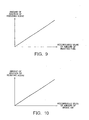
- the following methods exemplified as a method of deciding an amount of addition of the reducing agent when an amount of reducing agent is added to the reducing agent addition amount in the ordinary-time rich spike control in accordance with the amount of NOx occluded in the NOx catalyst 9. That is, (1) the amount of addition is increased in accordance with the increasing operation time of the internal combustion engine 1 from the end of execution of the last rich spike control (see Fig. 8); or (2) the amount of addition is increased in accordance with the increasing integrated or accumulated value of the amount of injected fuel from the end of execution of the last rich spike control (see Fig. 9); or (3) the amount of addition is increased in accordance with the increasing integrated or accumulated value of the amount of intake air supplied to the engine from the end of execution of the last rich spike control (see Fig. 10).
- the rich spike control is prevented from being executed, as a result of which it is possible to harmonize the prevention of deterioration in the exhaust emissions and the reduction of fuel consumption with each other.
- the amount of NOx occluded in the NOx catalyst 9 at the start of the temperature raising control decreases, so that the amount of NOx inadvertently discharged from the NOx catalyst 9 when the temperature of the NOx catalyst 9 is raised under the temperature raising control is decreased. Accordingly, the deterioration of the exhaust emissions can be suppressed at the time of executing the temperature raising control.
- Fig. 11 is a flow chart showing a temperature raising control routine which is stored in advance in the ROM of the ECU19. This temperature raising control routine is executed by the ECU 19 as interrupt processing with the elapse of a predetermined time, the input of a pulse signal from the crank position sensor 17 or the like being made as a trigger.
- step S1001 the ECU 19 determines whether the temperature raising control execution condition holds. That is, the ECU 19 determines whether the amount of sulfur oxides (SOx) occluded in the NOx occlusive agent, which constitutes the NOx catalyst 9, is more than or equal to a predetermined amount; or whether the amount of particulate matter (PM) collected in the particulate filter, which constitutes the NOx catalyst 9, is more than or equal to a predetermined amount.
- SOx sulfur oxides
- PM particulate matter
- the ECU 19 determines that the temperature raising control execution condition does not hold, and terminates the execution of this routine.
- the ECU 19 determines that the temperature raising control execution condition holds, and the control flow advances to step S1002.
- step S1002 the ECU 19 executes the before-temperature-rise rich spike control as stated above.
- the processing in step S1002 corresponds to a nitrogen oxides reducing step in this embodiment.
- step S1003 the ECU 19 starts executing the temperature raising control.
- step S1004 the ECU 19 determines whether a temperature raising control execution termination condition holds.
- the following conditions are exemplified as the temperature raising control execution termination condition. That is, (1) the time elapsed from the start of execution of the temperature raising control is longer than or equal to a predetermined time; and (2) the amount of particulate matter (PM) collected in the particulate filter constituting the NOx catalyst 9 is less than a predetermined amount.
- step S1004 When it is determined in step S1004 that the temperature raising control execution termination condition does not hold, the ECU 19 repeatedly executes the process in the step S1004 until the temperature raising control execution termination condition holds.
- step S1004 When it is determined in step S1004 that the temperature raising control execution termination condition holds, the control flow of the ECU 19 advances to step S1005, and terminates the execution of the temperature raising control.
- step S1003 the processes from step S1003 to step S1005 correspond to a temperature raising step in this embodiment.
- the ECU 19 executes the temperature raising control routine in this manner, so that the amount of NOx occluded in the NOx catalyst 9 is decreased before the temperature raising control on the NOx catalyst 9 is executed. As a result, when the temperature raising control on the NOx catalyst 9 is executed, the amount of NOx inadvertently discharged from the NOx catalyst 9 is decreased, thereby suppressing the deterioration of the exhaust emissions at the time of executing the temperature raising control.
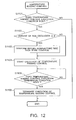
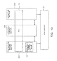
- Fig. 13 shows a block diagram of an exhaust emission control apparatus for an internal combustion engine in such a case.
- step S1102 the ECU 19 determines whether the amount of NOx occluded in the NOx catalyst 9 is more than or equal to a predetermined amount ⁇ .
- the amount of NOx occluded in the NOx catalyst 9 may be estimated by an estimating section 503 shown in Fig. 13 from the operation time of the internal combustion engine 1 from the end of execution of the last rich spike control, or the integrated or accumulated value of the amount of fuel injected from the end of execution of the last rich spike control, or the integrated or accumulated value of the amount of intake air from the end of execution of the last rich spike control.
- the estimating section 503 in this embodiment is constituted by the ECU 19.
- the processing in step S1102 includes an estimating step in this embodiment.
- step S1102 When it is determined in step S1102 that the amount of NOx occluded in the NOx catalyst 9 is more than or equal to the predetermined amount ⁇ , the ECU 19 executes the before-temperature-rise rich spike control in step S1103, and thereafter further executes the temperature raising control in step S1104 and the following steps. On the other hand, when it is determined in step S1102 that the amount of NOx occluded in the NOx catalyst 9 is less than the predetermined amount ⁇ , the ECU 19 executes the temperature raising control in step S1104 and the following steps while skipping the step S1103.
- the process in step S1103 corresponds to a nitrogen oxides reducing step in this embodiment, and the processes from step S1104 to step S1106 correspond to a temperature raising step in this embodiment.
- control flow may be carried out as follows. That is, it is determined again that the amount of NOx occluded the NOx catalyst 9 is more than or equal to the predetermined amount ⁇ after execution of the before-temperature-rise rich spike control in step S1103. Only when the amount of NOx occluded in the NOx catalyst 9 is less than the predetermined amount ⁇ , the temperature raising control in step S1104 and the following steps is executed, whereas when the amount of NOx occluded in the NOx catalyst 9 is more than or equal to the predetermined amount ⁇ , the before-temperature-rise rich spike control in step S1103 is performed continuously.
- the operation of the temperature raising section 502 may be permitted by means of an operation control section 505 on the condition that the amount of nitrogen oxides estimated by the estimating section 503 is less than the predetermined value.
- the operation control section 505 in this embodiment is constituted by the ECU 19.
- the execution of the temperature raising control is permitted when the amount of NOx occluded in the NOx catalyst 9 is less than the predetermined amount, whereas when the amount of NOx occluded in the NOx catalyst 9 is more than or equal to the predetermined amount, the execution of the temperature raising control is not permitted as long as the before-temperature-rise rich spike control is not executed.
- the present invention is also applicable to an internal combustion engine of spark ignition type (gasoline engine), and in this case, the fuel injection valves 3 may inject fuel directly into the cylinders 2, or they may inject fuel into the intake passage 7.
- the amount of nitrogen oxides discharged from the NOx catalyst when the temperature of the NOx catalyst is raised can be decreased, thereby making it possible to suppress the deterioration of the exhaust emissions upon raising the temperature of the NOx catalyst.
Abstract
Description
Claims (16)
- An exhaust emission control apparatus for an internal combustion engine characterized by:an NOx catalyst(9) disposed in an exhaust passage(8) of said internal combustion engine;a temperature raising section(502) for raising the temperature of said NOx catalyst(9); anda nitrogen oxides reducing section(501) for reducing an amount of nitrogen oxides occluded in said NOx catalyst(9) before said temperature raising section(502) is operated to raise the temperature of said NOx catalyst(9).
- The exhaust emission control apparatus for an internal combustion engine as set forth in claim 1, characterized in that said nitrogen oxides reducing section(501) comprises a reducing agent supplying section(504) for supplying a reducing agent to said NOx catalyst(9).
- The exhaust emission control apparatus for an internal combustion engine as set forth in claim 2, characterized in that said reducing agent supplying section(504) supplies said reducing agent to said NOx catalyst(9) by performing the sub-injection of fuel on at least one of an intake stroke, an expansion stroke and an exhaust stroke of said internal combustion engine.
- The exhaust emission control apparatus for an internal combustion engine as set forth in claim 2, characterized in that said reducing agent supplying section(504) supplies said reducing agent to said NOx catalyst(9) by adding said reducing agent to an exhaust from a reducing agent addition valve(14) disposed on said exhaust passage(8) of said internal combustion engine.
- The exhaust emission control apparatus for an internal combustion engine as set forth in claim 1, characterized by an estimating section(503) for estimating the amount of nitrogen oxides occluded in said NOx catalyst(9),
wherein when the amount of nitrogen oxides estimated by said estimating section(503) is less than a predetermined amount, said nitrogen oxides reducing section(501) does not reduce the amount of said nitrogen oxides occluded in said NOx catalyst(9). - An exhaust emission control apparatus for an internal combustion engine characterized by:an NOx catalyst(9) disposed in an exhaust passage(8) of said internal combustion engine;a temperature raising section(502) for raising the temperature of said NOx catalyst(9);a first reducing agent supplying section(504a) for supplying a reducing agent to said NOx catalyst(9) when an amount of nitrogen oxides occluded in said NOx catalyst(9) becomes more than or equal to a predetermined amount; anda second reducing agent supplying section(504b) for supplying an amount of said reducing agent more than that supplied by said first reducing agent supplying section(504a) to said NOx catalyst(9) before said temperature raising section(502) is operated to raise the temperature of said NOx catalyst(9).
- The exhaust emission control apparatus for an internal combustion engine as set forth in claim 6, characterized in that said second reducing agent supplying section(504b) increases the amount of reducing agent to be supplied in accordance with the increasing amount of nitrogen oxides occluded in said NOx catalyst(9).
- An exhaust emission control apparatus for an internal combustion engine characterized by:an NOx catalyst(9) disposed in an exhaust passage(8) of said internal combustion engine;a temperature raising section(502) for raising the temperature of said NOx catalyst(9);an estimating section(503) for estimating an amount of nitrogen oxides occluded in said NOx catalyst(9); andan operation control section(505) adapted to permit an operation of said temperature raising section(502) when the amount of nitrogen oxides estimated by said estimating section(503) is less than a predetermined amount.
- The exhaust emission control apparatus for an internal combustion engine as set forth in any one of claims 1 through 8, characterized in that said temperature raising section(502) raises the temperature of said NOx catalyst(9) when poisoning of said NOx catalyst(9) due to sulfur oxide is removed.
- The exhaust emission control apparatus for an internal combustion engine as set forth in any one of claims 1 through 8, characterized in that said NOx catalyst(9) comprises:wherein said temperature raising section(502) raises the temperature of said NOx catalyst(9) when said particulate matter collected by said particulate filter is removed.an NOx occlusive agent being operable to occlude said nitrogen oxides in an exhaust when the air fuel ratio of the exhaust flowing into the NOx catalyst(9) is lean, and discharge and reduce the occluded nitrogen oxides when the oxygen concentration of the exhaust flowing into the NOx catalyst(9) is reduced ; anda particulate filter for collecting particulate matter in said exhaust;
- An exhaust emission control method for an internal combustion engine characterized by:a temperature raising step(S1003∼S1005) for raising the temperature of an NOx catalyst(9) disposed in an exhaust passage(8) of said internal combustion engine; andan nitrogen oxides reducing step(S1002) for reducing an amount of nitrogen oxides occluded in said NOx catalyst(9) before said temperature raising step(S1003∼S1005).
- The exhaust emission control method for an internal combustion engine as set forth in claim 11, characterized in that in said nitrogen oxides reducing step(S1002), the amount of nitrogen oxides occluded in said NOx catalyst(9) is reduced by supplying a reducing agent to said NOx catalyst(9).
- The exhaust emission control method for an internal combustion engine as set forth in claim 11, characterized by an estimating step(S1102) for estimating the amount of nitrogen oxides occluded in said NOx catalyst(9) before said nitrogen oxides reducing step(S1103),
wherein said nitrogen oxides reducing step(S1103) is not performed when the amount of nitrogen oxides estimated in said estimating step(S1102) is less than a predetermined amount. - An exhaust emission control method for an internal combustion engine characterized by:wherein an amount of reducing agent supplied to said NOx catalyst(9) is increased in said nitrogen oxides reducing step(S1002) before said temperature raising step(S1003∼S1005).a temperature raising step(S1003∼S1005) for raising the temperature of an NOx catalyst(9) disposed in an exhaust passage(8) of said internal combustion engine; anda nitrogen oxides reducing step(S1002) for reducing an amount of nitrogen oxides occluded in said NOx catalyst(9) by supplying a reducing agent to said NOx catalyst(9) when the amount of nitrogen oxides occluded in said NOx catalyst(9) becomes more than or equal to a predetermined amount;
- The exhaust emission control method for an internal combustion engine as set forth in claim 14, characterized in that the amount of reducing agent is increased in accordance with the increasing amount of said nitrogen oxides occluded in said NOx catalyst(9) in said nitrogen oxides reducing step(S1002) before said temperature raising step(S1003∼S1005).
- An exhaust emission control method for an internal combustion engine characterized by:an estimating step(S1102) for estimating an amount of nitrogen oxides occluded in an NOx catalyst(9) disposed in an exhaust passage(8) of said internal combustion engine; anda temperature raising step(S1104∼S1106) for raising the temperature of said NOx catalyst(9) on the condition that the amount of nitrogen oxides estimated in said estimating step(S1102) is less than a predetermined amount.
Applications Claiming Priority (2)
| Application Number | Priority Date | Filing Date | Title |
|---|---|---|---|
| JP2002358555 | 2002-12-10 | ||
| JP2002358555A JP4385593B2 (en) | 2002-12-10 | 2002-12-10 | Exhaust gas purification device for internal combustion engine |
Publications (2)
| Publication Number | Publication Date |
|---|---|
| EP1428567A1 true EP1428567A1 (en) | 2004-06-16 |
| EP1428567B1 EP1428567B1 (en) | 2009-08-05 |
Family
ID=32322089
Family Applications (1)
| Application Number | Title | Priority Date | Filing Date |
|---|---|---|---|
| EP03027858A Expired - Lifetime EP1428567B1 (en) | 2002-12-10 | 2003-12-04 | Exhaust emission control apparatus for internal combustion engine |
Country Status (4)
| Country | Link |
|---|---|
| US (1) | US7111456B2 (en) |
| EP (1) | EP1428567B1 (en) |
| JP (1) | JP4385593B2 (en) |
| DE (1) | DE60328657D1 (en) |
Families Citing this family (29)
| Publication number | Priority date | Publication date | Assignee | Title |
|---|---|---|---|---|
| JP3858752B2 (en) * | 2002-04-25 | 2006-12-20 | トヨタ自動車株式会社 | Exhaust gas purification device for internal combustion engine |
| US7845162B2 (en) * | 2005-06-20 | 2010-12-07 | Cummins Filtration Ip, Inc | Apparatus, system, and method for diverting fluid |
| DE102005062120B4 (en) * | 2005-12-23 | 2016-06-09 | Robert Bosch Gmbh | Method and device for monitoring an exhaust aftertreatment system |
| US8195378B2 (en) * | 2008-07-28 | 2012-06-05 | Cummins Inc. | Emissions reductions through multiple fuel injection events |
| JP5067478B2 (en) * | 2009-05-15 | 2012-11-07 | トヨタ自動車株式会社 | Exhaust gas purification device for internal combustion engine |
| KR101339523B1 (en) | 2010-03-15 | 2013-12-10 | 도요타지도샤가부시키가이샤 | Exhaust purification system of internal combustion engine |
| CA2750738C (en) | 2010-03-15 | 2014-04-29 | Toyota Jidosha Kabushiki Kaisha | Exhaust purification system of internal combustion engine |
| EP2460987B1 (en) | 2010-04-01 | 2016-08-17 | Toyota Jidosha Kabushiki Kaisha | Exhaust gas purification method for internal combustion engine |
| CN102985647B (en) | 2010-07-28 | 2015-06-03 | 丰田自动车株式会社 | Exhaust purification apparatus for internal combustion engine |
| ES2554637T3 (en) | 2010-08-30 | 2015-12-22 | Toyota Jidosha Kabushiki Kaisha | Exhaust gas purification device for internal combustion engine |
| BRPI1014484B1 (en) | 2010-08-30 | 2020-08-11 | Toyota Jidosha Kabushiki Kaisha | INTERNAL COMBUSTION ENGINE EXHAUST PURIFICATION SYSTEM |
| CN103154455B (en) | 2010-10-04 | 2015-07-15 | 丰田自动车株式会社 | Exhaust gas purifying device for internal combustion engine |
| JP5168410B2 (en) | 2010-10-04 | 2013-03-21 | トヨタ自動車株式会社 | Exhaust gas purification device for internal combustion engine |
| JP5131393B2 (en) | 2010-10-18 | 2013-01-30 | トヨタ自動車株式会社 | Exhaust gas purification device for internal combustion engine |
| EP2484876B8 (en) | 2010-12-06 | 2016-09-14 | Toyota Jidosha Kabushiki Kaisha | Exhaust gas purification method for internal combustion engine |
| JP5182428B2 (en) | 2010-12-20 | 2013-04-17 | トヨタ自動車株式会社 | Exhaust gas purification device for internal combustion engine |
| JP5131389B2 (en) | 2010-12-24 | 2013-01-30 | トヨタ自動車株式会社 | Exhaust gas purification device for internal combustion engine |
| CN102753794B (en) | 2011-02-07 | 2015-05-13 | 丰田自动车株式会社 | Exhaust-gas purifying device for internal-combustion engine |
| EP2503120B1 (en) * | 2011-02-10 | 2016-09-14 | Toyota Jidosha Kabushiki Kaisha | Nox purification method of an exhaust-gas purifying system for internal-combustion engine |
| JP5152417B2 (en) | 2011-03-17 | 2013-02-27 | トヨタ自動車株式会社 | Exhaust gas purification device for internal combustion engine |
| WO2012140784A1 (en) | 2011-04-15 | 2012-10-18 | トヨタ自動車株式会社 | Exhaust cleaner for internal combustion engine |
| JP5354104B1 (en) | 2011-11-07 | 2013-11-27 | トヨタ自動車株式会社 | Exhaust gas purification device for internal combustion engine |
| JP5288055B1 (en) | 2011-11-09 | 2013-09-11 | トヨタ自動車株式会社 | Exhaust gas purification device for internal combustion engine |
| US9175590B2 (en) | 2011-11-30 | 2015-11-03 | Toyota Jidosha Kabushiki Kaisha | Exhaust purification system of internal combustion engine |
| WO2013080330A1 (en) | 2011-11-30 | 2013-06-06 | トヨタ自動車株式会社 | Exhaust purification device for internal combustion engine |
| ES2629482T3 (en) | 2012-02-07 | 2017-08-10 | Toyota Jidosha Kabushiki Kaisha | Exhaust gas purification device for internal combustion engine |
| JP5673861B2 (en) * | 2013-02-05 | 2015-02-18 | トヨタ自動車株式会社 | Exhaust gas purification device for internal combustion engine |
| CN104204434B (en) * | 2013-02-20 | 2016-12-07 | 丰田自动车株式会社 | The emission-control equipment of internal combustion engine |
| JP2017194022A (en) * | 2016-04-21 | 2017-10-26 | トヨタ自動車株式会社 | Control device for exhaust emission control device |
Citations (4)
| Publication number | Priority date | Publication date | Assignee | Title |
|---|---|---|---|---|
| US5657625A (en) | 1994-06-17 | 1997-08-19 | Mitsubishi Jidosha Kogyo Kabushiki Kaisha | Apparatus and method for internal combustion engine control |
| EP0862941A2 (en) * | 1997-03-04 | 1998-09-09 | Toyota Jidosha Kabushiki Kaisha | An exhaust gas purification device for an internal combustion engine |
| EP0892158A2 (en) * | 1997-07-19 | 1999-01-20 | Volkswagen Aktiengesellschaft | Method and device to monitor the desulphurization of NOx storage catalytic converters |
| EP1108876A2 (en) * | 1999-12-16 | 2001-06-20 | Toyota Jidosha Kabushiki Kaisha | Internal combustion engine |
Family Cites Families (12)
| Publication number | Priority date | Publication date | Assignee | Title |
|---|---|---|---|---|
| JP2722987B2 (en) | 1992-09-28 | 1998-03-09 | トヨタ自動車株式会社 | Exhaust gas purification device for internal combustion engine |
| JP3440654B2 (en) | 1994-11-25 | 2003-08-25 | トヨタ自動車株式会社 | Exhaust gas purification device |
| JP3899534B2 (en) | 1995-08-14 | 2007-03-28 | トヨタ自動車株式会社 | Exhaust gas purification method for diesel engine |
| JP3067685B2 (en) * | 1997-03-31 | 2000-07-17 | 三菱自動車工業株式会社 | Exhaust purification system for spark ignition type direct injection type internal combustion engine |
| US6367246B1 (en) * | 1997-04-24 | 2002-04-09 | Toyota Jidosha Kabushiki Kaisha | Exhaust gas purification device for internal combustion engine |
| US5974788A (en) * | 1997-08-29 | 1999-11-02 | Ford Global Technologies, Inc. | Method and apparatus for desulfating a nox trap |
| US6233925B1 (en) * | 1998-08-28 | 2001-05-22 | Toyota Jidosha Kabushiki Kaisha | Exhaust discharge control device for internal combustion engine |
| JP3680650B2 (en) * | 1999-01-25 | 2005-08-10 | トヨタ自動車株式会社 | Exhaust gas purification device for internal combustion engine |
| JP3632483B2 (en) * | 1999-02-05 | 2005-03-23 | マツダ株式会社 | Engine control device |
| JP3487209B2 (en) | 1999-02-23 | 2004-01-13 | トヨタ自動車株式会社 | Exhaust gas purification device for internal combustion engine |
| JP2001303980A (en) | 2000-04-27 | 2001-10-31 | Toyota Motor Corp | Exhaust emission control device of internal combustion engine |
| JP2003065042A (en) | 2001-08-30 | 2003-03-05 | Toyota Motor Corp | Exhaust emission control device for internal combustion engine |
-
2002
- 2002-12-10 JP JP2002358555A patent/JP4385593B2/en not_active Expired - Fee Related
-
2003
- 2003-12-01 US US10/724,154 patent/US7111456B2/en not_active Expired - Lifetime
- 2003-12-04 DE DE60328657T patent/DE60328657D1/en not_active Expired - Lifetime
- 2003-12-04 EP EP03027858A patent/EP1428567B1/en not_active Expired - Lifetime
Patent Citations (4)
| Publication number | Priority date | Publication date | Assignee | Title |
|---|---|---|---|---|
| US5657625A (en) | 1994-06-17 | 1997-08-19 | Mitsubishi Jidosha Kogyo Kabushiki Kaisha | Apparatus and method for internal combustion engine control |
| EP0862941A2 (en) * | 1997-03-04 | 1998-09-09 | Toyota Jidosha Kabushiki Kaisha | An exhaust gas purification device for an internal combustion engine |
| EP0892158A2 (en) * | 1997-07-19 | 1999-01-20 | Volkswagen Aktiengesellschaft | Method and device to monitor the desulphurization of NOx storage catalytic converters |
| EP1108876A2 (en) * | 1999-12-16 | 2001-06-20 | Toyota Jidosha Kabushiki Kaisha | Internal combustion engine |
Also Published As
| Publication number | Publication date |
|---|---|
| JP2004190551A (en) | 2004-07-08 |
| US7111456B2 (en) | 2006-09-26 |
| JP4385593B2 (en) | 2009-12-16 |
| DE60328657D1 (en) | 2009-09-17 |
| US20040107694A1 (en) | 2004-06-10 |
| EP1428567B1 (en) | 2009-08-05 |
Similar Documents
| Publication | Publication Date | Title |
|---|---|---|
| EP1428567B1 (en) | Exhaust emission control apparatus for internal combustion engine | |
| US7506502B2 (en) | Exhaust gas purifying system for internal combustion engine | |
| KR100658818B1 (en) | Exhaust purifying apparatus and exhaust purifying method for internal combustion engine | |
| US7607290B2 (en) | Exhaust purifying apparatus for internal combustion engine | |
| US7886521B2 (en) | Diagnosis device of exhaust purification catalyst | |
| EP2559876A1 (en) | Exhaust gas purification device, and control method for exhaust gas purification device | |
| EP1326010A2 (en) | Exhaust gas purification apparatus and process for internal combustion engine | |
| JP4174685B1 (en) | Exhaust gas purification device for internal combustion engine | |
| US7827783B2 (en) | Exhaust gas purifying apparatus for internal combustion engine | |
| EP1725747B1 (en) | Exhaust purifying apparatus for internal combustion engine | |
| RU2645101C1 (en) | Emission control system and emission control method for internal combustion engine | |
| JP5761255B2 (en) | Exhaust gas purification device for internal combustion engine | |
| EP1515014B1 (en) | Exhaust purifying apparatus of internal combustion engine | |
| EP1471219B1 (en) | Exhaust gas cleaning system and SOx poisoning recovery method for internal combustion engine | |
| US8020375B2 (en) | Exhaust gas purification system for internal combustion engine | |
| EP1512848B1 (en) | Exhaust purifying apparatus and method for purifying exhaust gas | |
| JP4489504B2 (en) | Diesel engine exhaust purification system | |
| JP4069043B2 (en) | Exhaust gas purification device for internal combustion engine | |
| JP2005240682A (en) | Exhaust emission control device for internal combustion engine | |
| US20220186643A1 (en) | Exhaust purification system of internal combustion engine | |
| WO2013136470A1 (en) | Exhaust gas purification device for internal combustion engine | |
| JP2005127286A (en) | Exhaust emission cleaning device for internal combustion engine | |
| JP2005076509A (en) | Exhaust emission control device for internal combustion engine |
Legal Events
| Date | Code | Title | Description |
|---|---|---|---|
| PUAI | Public reference made under article 153(3) epc to a published international application that has entered the european phase |
Free format text: ORIGINAL CODE: 0009012 |
|
| 17P | Request for examination filed |
Effective date: 20031222 |
|
| AK | Designated contracting states |
Kind code of ref document: A1 Designated state(s): AT BE BG CH CY CZ DE DK EE ES FI FR GB GR HU IE IT LI LU MC NL PT RO SE SI SK TR |
|
| AX | Request for extension of the european patent |
Extension state: AL LT LV MK |
|
| 17Q | First examination report despatched |
Effective date: 20040729 |
|
| AKX | Designation fees paid |
Designated state(s): DE FR GB |
|
| GRAP | Despatch of communication of intention to grant a patent |
Free format text: ORIGINAL CODE: EPIDOSNIGR1 |
|
| GRAS | Grant fee paid |
Free format text: ORIGINAL CODE: EPIDOSNIGR3 |
|
| GRAA | (expected) grant |
Free format text: ORIGINAL CODE: 0009210 |
|
| AK | Designated contracting states |
Kind code of ref document: B1 Designated state(s): DE FR GB |
|
| REG | Reference to a national code |
Ref country code: GB Ref legal event code: FG4D |
|
| REF | Corresponds to: |
Ref document number: 60328657 Country of ref document: DE Date of ref document: 20090917 Kind code of ref document: P |
|
| PLBE | No opposition filed within time limit |
Free format text: ORIGINAL CODE: 0009261 |
|
| STAA | Information on the status of an ep patent application or granted ep patent |
Free format text: STATUS: NO OPPOSITION FILED WITHIN TIME LIMIT |
|
| 26N | No opposition filed |
Effective date: 20100507 |
|
| REG | Reference to a national code |
Ref country code: GB Ref legal event code: 746 Effective date: 20120917 |
|
| REG | Reference to a national code |
Ref country code: DE Ref legal event code: R084 Ref document number: 60328657 Country of ref document: DE Effective date: 20120924 |
|
| REG | Reference to a national code |
Ref country code: FR Ref legal event code: PLFP Year of fee payment: 13 |
|
| REG | Reference to a national code |
Ref country code: FR Ref legal event code: PLFP Year of fee payment: 14 |
|
| REG | Reference to a national code |
Ref country code: FR Ref legal event code: PLFP Year of fee payment: 15 |
|
| PGFP | Annual fee paid to national office [announced via postgrant information from national office to epo] |
Ref country code: FR Payment date: 20211109 Year of fee payment: 19 Ref country code: GB Payment date: 20211028 Year of fee payment: 19 Ref country code: DE Payment date: 20211102 Year of fee payment: 19 |
|
| REG | Reference to a national code |
Ref country code: DE Ref legal event code: R119 Ref document number: 60328657 Country of ref document: DE |
|
| GBPC | Gb: european patent ceased through non-payment of renewal fee |
Effective date: 20221204 |
|
| PG25 | Lapsed in a contracting state [announced via postgrant information from national office to epo] |
Ref country code: GB Free format text: LAPSE BECAUSE OF NON-PAYMENT OF DUE FEES Effective date: 20221204 Ref country code: DE Free format text: LAPSE BECAUSE OF NON-PAYMENT OF DUE FEES Effective date: 20230701 |
|
| PG25 | Lapsed in a contracting state [announced via postgrant information from national office to epo] |
Ref country code: FR Free format text: LAPSE BECAUSE OF NON-PAYMENT OF DUE FEES Effective date: 20221231 |