EP1422713A2 - Hard disk drive storage system - Google Patents
Hard disk drive storage system Download PDFInfo
- Publication number
- EP1422713A2 EP1422713A2 EP03013055A EP03013055A EP1422713A2 EP 1422713 A2 EP1422713 A2 EP 1422713A2 EP 03013055 A EP03013055 A EP 03013055A EP 03013055 A EP03013055 A EP 03013055A EP 1422713 A2 EP1422713 A2 EP 1422713A2
- Authority
- EP
- European Patent Office
- Prior art keywords
- hard disk
- disk drive
- connector
- storage system
- data
- Prior art date
- Legal status (The legal status is an assumption and is not a legal conclusion. Google has not performed a legal analysis and makes no representation as to the accuracy of the status listed.)
- Withdrawn
Links
Images


Classifications
-
- G—PHYSICS
- G11—INFORMATION STORAGE
- G11B—INFORMATION STORAGE BASED ON RELATIVE MOVEMENT BETWEEN RECORD CARRIER AND TRANSDUCER
- G11B33/00—Constructional parts, details or accessories not provided for in the other groups of this subclass
- G11B33/12—Disposition of constructional parts in the apparatus, e.g. of power supply, of modules
- G11B33/125—Disposition of constructional parts in the apparatus, e.g. of power supply, of modules the apparatus comprising a plurality of recording/reproducing devices, e.g. modular arrangements, arrays of disc drives
- G11B33/126—Arrangements for providing electrical connections, e.g. connectors, cables, switches
-
- G—PHYSICS
- G11—INFORMATION STORAGE
- G11B—INFORMATION STORAGE BASED ON RELATIVE MOVEMENT BETWEEN RECORD CARRIER AND TRANSDUCER
- G11B17/00—Guiding record carriers not specifically of filamentary or web form, or of supports therefor
- G11B17/22—Guiding record carriers not specifically of filamentary or web form, or of supports therefor from random access magazine of disc records
- G11B17/225—Guiding record carriers not specifically of filamentary or web form, or of supports therefor from random access magazine of disc records wherein the disks are transferred from a fixed magazine to a fixed playing unit using a moving carriage
-
- G—PHYSICS
- G11—INFORMATION STORAGE
- G11B—INFORMATION STORAGE BASED ON RELATIVE MOVEMENT BETWEEN RECORD CARRIER AND TRANSDUCER
- G11B25/00—Apparatus characterised by the shape of record carrier employed but not specific to the method of recording or reproducing, e.g. dictating apparatus; Combinations of such apparatus
- G11B25/04—Apparatus characterised by the shape of record carrier employed but not specific to the method of recording or reproducing, e.g. dictating apparatus; Combinations of such apparatus using flat record carriers, e.g. disc, card
- G11B25/043—Apparatus characterised by the shape of record carrier employed but not specific to the method of recording or reproducing, e.g. dictating apparatus; Combinations of such apparatus using flat record carriers, e.g. disc, card using rotating discs
-
- G—PHYSICS
- G11—INFORMATION STORAGE
- G11B—INFORMATION STORAGE BASED ON RELATIVE MOVEMENT BETWEEN RECORD CARRIER AND TRANSDUCER
- G11B33/00—Constructional parts, details or accessories not provided for in the other groups of this subclass
- G11B33/12—Disposition of constructional parts in the apparatus, e.g. of power supply, of modules
- G11B33/125—Disposition of constructional parts in the apparatus, e.g. of power supply, of modules the apparatus comprising a plurality of recording/reproducing devices, e.g. modular arrangements, arrays of disc drives
- G11B33/127—Mounting arrangements of constructional parts onto a chassis
- G11B33/128—Mounting arrangements of constructional parts onto a chassis of the plurality of recording/reproducing devices, e.g. disk drives, onto a chassis
-
- G—PHYSICS
- G06—COMPUTING; CALCULATING OR COUNTING
- G06F—ELECTRIC DIGITAL DATA PROCESSING
- G06F3/00—Input arrangements for transferring data to be processed into a form capable of being handled by the computer; Output arrangements for transferring data from processing unit to output unit, e.g. interface arrangements
- G06F3/06—Digital input from, or digital output to, record carriers, e.g. RAID, emulated record carriers or networked record carriers
- G06F2003/0697—Digital input from, or digital output to, record carriers, e.g. RAID, emulated record carriers or networked record carriers device management, e.g. handlers, drivers, I/O schedulers
-
- G—PHYSICS
- G06—COMPUTING; CALCULATING OR COUNTING
- G06F—ELECTRIC DIGITAL DATA PROCESSING
- G06F3/00—Input arrangements for transferring data to be processed into a form capable of being handled by the computer; Output arrangements for transferring data from processing unit to output unit, e.g. interface arrangements
- G06F3/06—Digital input from, or digital output to, record carriers, e.g. RAID, emulated record carriers or networked record carriers
- G06F3/0601—Interfaces specially adapted for storage systems
Definitions
- the invention generally pertains to storage systems, and more specifically, to hard disk drive storage systems.
- Storage systems or autochangers, are commonly used to store data cartridges at known locations and to retrieve the desired data cartridges so that data may be written to and/or read from the data cartridges. Accordingly, large volumes of computer-readable data can be stored on numerous data cartridges and accessed by one or more computers connected to the storage system (e.g., over a network).
- Such storage systems may include one or more storage magazines and cartridge read/write devices.
- the storage magazines serve as a storage location for the data cartridges, and the read/write device(s) provide access to the data stored on the data cartridges.
- the storage system may also include a controller operatively associated with a picker assembly as well as a drive system for moving the picker assembly among the data cartridges stored in the storage system.
- the controller receives an instruction to access a certain data cartridge, the controller causes the drive system to move the picker assembly to the location of the desired data cartridge. Then, the picker assembly retrieves the data cartridge and delivers it to the read/write device. The picker assembly may also be operated to return the data cartridge to the storage magazine following the read/write operation.
- Typical data cartridges have relatively slow access times. For example, once the data cartridge has been delivered to the read/write device, it may take another 4 to 6 minutes to position the read/write head before the read/write operation can begin.
- Hard disk drives have much faster access times. For example, positioning the read/write head provided with a typical hard disk drive may take only about 10 to 15 ms before the read/write operation can begin.
- hard disk drives have generally been more expensive than data cartridges. But recently, the cost of hard disk drives is approaching the cost of data cartridges, and therefore hard disk drives are becoming more common for mass storage solutions than they have been in the past. For example, hard disk drives are typically provided for RAID (i.e., random array of independent disks) storage systems.
- RAID random array of independent disks
- hard disk drives used in RAID storage systems are always connected, even when not in use.
- Hard disk drives provided in an "always-connected" system are subject to wear and tear (e.g., from heat) or even permanent damage or data loss (e.g., during a power surge).
- extensive cabling is required to link each of the hard disk drives in such a system.
- One embodiment of a hard disk drive storage system comprises a library, at least one storage device mounted in the library, and at least one connector mounted in the library. At least one hard disk drive is receivable in the at least one storage device and alternately receivable adjacent the at least one connector.
- a picker assembly is movably mounted in the library, the picker assembly delivering the at least one hard disk drive between the at least one storage device and the at least one connector.
- An embodiment of a method for accessing data from a plurality of hard disk drives in a storage system comprises storing the plurality of hard disk drives in the storage system, transporting one of the plurality of hard disk drives to a connector in the storage system, connecting the transported hard disk drive to the connector for a read/write operation, and disconnecting the connected hard disk drive from the connector following the read/write operation.
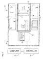
- a hard disk drive storage system 10 is shown and described herein according to embodiments of the invention as it may be used to store large volumes of computer-readable data on a number of hard disk drives 12.
- One or more users may link to the storage system 10 (FIG. 1) from a computer 15 (e.g., over a network, direct connection, etc.) via suitable control circuitry,(e.g., controller 19).
- the hard disk drive storage system 10 may comprise a library 14 having a number of storage devices 16 (e.g., storage magazines) and at least one data-access device 18 mounted therein.
- the storage devices 16 and the data-access device 18 may be arranged in any suitable configuration, such as the generally U-shaped configuration shown in FIG. 1.
- the library 12 is shown with the storage devices 16 and the data-access device 18 arranged in a particular configuration in FIG. 1, other suitable configurations are also contemplated as being within the scope of the invention.
- the number of storage devices 16 and data-access devices 18 provided in the library 12 may depend upon various design considerations. Such considerations may include, but are not limited to, the frequency with which data is accessed. Other considerations may include the physical dimensions of the library 12.
- the library 12 may also be provided with a picker assembly 28.
- the picker assembly 28 is adapted to engage one of the hard disk drives 12, to withdraw the hard disk drive 12 (e.g., from one of the storage devices 16), to transport the hard disk drive 12 within the library 12, and to eject the data cartridge 20 at the intended destination (e.g., the data-access device 18).
- a guide system 24 may be mounted in the library 14 and defines a displacement path 26 adjacent the storage devices 16 and the data-access device 18.
- the guide system 24 may comprise a rail having a gear track mounted thereto.
- other embodiments of the guide system 24 are also contemplated as being within the scope of the invention and may be readily provided by one skilled in the art after having become familiar with the teachings of the present invention.
- the picker assembly 28 is operatively associated with the guide system 24 and is movable along the displacement path 26 to access the hard disk drives 12 in the library 14.
- the picker assembly 28 may comprise an actuator assembly 30 having a drive motor operatively associated with a gear assembly.
- the gear assembly may engage the gear track on the guide system 24 and move the picker assembly 28 on the guide system 24 in the library 14.
- a suitable controller 19 is operatively associated with the picker assembly 28 to transport the hard disk drives 12 within the library 14, for example, between the data-access device 18 and the storage devices 16.
- the picker assembly 28 is shown in positions 17, 17', and 17" in FIG. 1.
- the picker assembly 28 is shown positioned adjacent the storage devices 16 at positions 17 and 17", and is shown positioned adjacent the data-access device 18 at position 17'.
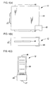
- the picker assembly 28 may comprise a housing 34 that defines a cavity 36 sized to receive the hard disk drive 12.
- a plunge mechanism or "thumb assembly” 38 is slidably mounted to the housing 34 so that the thumb assembly 38 may be moved toward and away from the cartridge access end 40 of the housing 34, generally in the directions indicated by arrows 41 and 42, respectively.
- the hard disk drive 12 may comprise a housing 44.
- One or more guide members 46, 47 may be mounted to or integrally formed with the housing 44 of the hard disk drive 12.
- the guide members 46, 47 cooperate with mating storage device guides 52 (FIG. 5) that may be provided on the storage device 16 to align the hard disk drive 12 when it is being inserted and withdrawn therefrom. Accordingly, the hard disk drive 12 may be readily inserted in and withdrawn from the storage device 16 without binding.
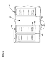
- FIG. 5 An embodiment of the storage device 16 is shown in FIG. 5, wherein the storage device is a storage magazine.
- the storage device 16 may comprise a housing 51 having a number of storage chambers 50 formed therein, each sized to receive at least one of the hard disk drives 12.
- the storage device 16 is removable from the library 14. According to such an embodiment, one of the storage devices 16 may be readily removed and replaced with another storage device 16.
- the storage device 16 may comprise guides 52 that cooperate with the guide members 46, 47 to align the hard disk drives 12 therein.
- the guides 52 may comprise recesses or channels that are formed in the housing 51.
- the guides 52 may comprise a rail (e.g., a cylinder or rod).
- the guides 52 may be any suitable shape so as to cooperate with the guide member 46, 47 mounted to the hard disk drives 12. In any event, the guide members 46, 47 readily slide along the guides 52 to guide the hard disk drive 12 into the storage chamber 50 formed therein.
- the guide members 46, 47 may be mounted in any suitable position on the hard disk drive 12.
- the guide members 46, 47 may be provided on the sides of the hard disk drive 12.
- the mating guides 52, 56 may be provided on the sidewalls or partitions in the storage device 16 and the data-access device 18.
- the guide members 46, 47 are preferably made of a stiff material (e.g., a hard plastic or metal), the guide members 46, 47 may be manufactured from any suitable material.
- the guide members 46, 47 may be any suitable shape.
- the guide members 46, 47 may be "fins” or “blades”, such as those shown in FIG. 4(a) through FIG. 4(c).
- the guide members 46, 47 may be substantially "T-shaped", or may form circular openings that cooperate with cylindrical guides in the storage devices 16 and the data-access device 18.
- the hard disk drive 12 may also comprise a connector 22 mounted to the housing 44, as shown in FIG. 4(a) through FIG. 4(b).
- the connector 22 provides a link from the hard disk drive 12 to the data-access device 18 (e.g., mating connector 20).
- the connectors 20 on the data-access device 18 may be linked to a controller 19 or directly to the user's computer (e.g., over a network). Accordingly, the hard disk drive 12 may be linked to the user's computer when the hard disk drive 12 is connected to the data-access device 18.
- the connector 22 may be any suitable connector.
- the connector 22 may comprise multiple connections or pins, including pins for data transfer, power, and ground.
- the connector 22 may be a "hot swappable" connector so that the hard disk drive 12 can be readily connected without having to power down the data-access device 18.
- the connector 22 may be a readily-available single connector attachment (SCA) such as those used in RAID storage systems. SCA connectors provide the conventional 68-pin data connection, 4-pin power connection, and configuration jumpers on a single 80-pin connector.
- SCA single connector attachment
- the hard disk drive 12 may also comprise a bracket member 48 mounted to (or integrally formed as part of) the housing 44.
- the bracket member 48 cooperates with the thumb assembly 38 on the picker assembly 28 so that the thumb assembly 38 engages the bracket member to withdraw the hard disk drive 12 from the data-access device 18 and the storage device 16.
- the bracket member 48 may instead be a notch formed in the housing 44 of the hard disk drive 12 that cooperates with the thumb assembly 38 on the picker assembly 28.
- the picker assembly 28 comprises an alternative retrieval mechanism
- a suitable alternative to the bracket member 48 may also be provided to cooperate therewith.
- the hard disk drive 12 may be provided with machine-readable indicia 49 (e.g., a bar code label). It is understood that the machine-readable indicia 49 may comprise any suitable indicia, and is not limited to the bar code label shown and described herein. For example, the machine-readable indicia 49 may comprise a transponder. In any event, the machine-readable indicia 49 may be read with a suitable reader and control circuitry and used to identify the data cartridges 12 in the library 14.
- machine-readable indicia 49 e.g., a bar code label
- the machine-readable indicia 49 may comprise any suitable indicia, and is not limited to the bar code label shown and described herein.
- the machine-readable indicia 49 may comprise a transponder.
- the machine-readable indicia 49 may be read with a suitable reader and control circuitry and used to identify the data cartridges 12 in the library 14.
- the machine-readable indicia 49 is a bar code label
- a bar code scanner may be provided on the picker assembly 28 so that the bar code labels can be read from the hard disk drives 12 as the picker assembly 28 is moved along the displacement path 26 in the library 14.
- inductive readers may be provided adjacent the transponder in each the storage devices 16 and in the data-access device 18 to activate and read the information from the transponder.
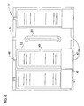
- the data-access device 18 may comprise a backplane 58 having one or more connectors 20 mounted thereto.
- the number of connectors 20 mounted on the backplane may vary according to design considerations. For example, more connectors 20 provided on the backplane 58 allow more hard disk drives 12 to be simultaneously accessed.
- the connectors 20 are each linked to a power source (not shown) which provides electrical power to the hard disk drive 12 when it is linked to the connector 20 at the data-access device 18.
- the connectors 20 also provide a data transfer connection (e.g., through control circuitry 19) that can be used to perform the read/write operations requested by the user(s).
- the data-access device 18 may also comprise a housing 54.
- the housing 54 may be manufactured similarly to the housing 46 of the storage device 16. Indeed, in some embodiments the data-access device 18 may be removable from the library 14 (e.g., so that it can be easily replaced).
- the guides 56 function similarly to the guides 52 in the storage devices 16 to align the hard disk drive 12 when it is inserted therein.
- the guides 56 align the connector 22 on the hard disk drive 12 with the connector 20 mounted on the backplane 58 of the data-access device 18 so that the connectors 20, 22 can be linked to one another.
- the guides 56 may be any suitable shape to cooperate with the guide member 46, 47 on the hard disk drives 12.
- the hard disk drive storage system 10 may be operated as follows, according to one embodiment of the invention.
- the controller (not shown) signals the picker assembly 28 to retrieve one of the hard disk drives 12 from one of the storage devices 16.
- the picker assembly 28 is moved along the displacement path 26 on the positioning rail 24 so that it is adjacent the selected data cartridge 12 in the storage device 16. Although a data-access device 18 is shown in FIG. 7, the operation of the picker assembly 28 to retrieve one of the hard disk drives 12 from the storage device 16 is similar for purposes of illustration.
- the plunge mechanism 38 is moved in the direction of arrow 41 until it engages the hard disk drive 12.
- the arrangement of the plunge mechanism 38 is such that it engages the bracket member 48 on the hard disk drive 12 when the plunge mechanism 38 is at or near its fully-extended position.
- the plunge mechanism 38 reverses direction, generally as shown by arrow 42 in FIG. 7. Accordingly, the engaged hard disk drive 12 is withdrawn from the storage device 16 and is received in the cartridge-receiving cavity 36 defined by the housing 40 of the picker assembly 28. The plunge mechanism 38 continues to retract until the hard disk drive 12 is received within the cartridge-receiving cavity 36 of the picker assembly 28 by an amount sufficient to allow the picker assembly 28 to move to another location in the library 14.
- the picker assembly 28 is moved to the data-access device 18.
- the picker assembly 28 then ejects the hard disk drive 12 by moving the plunge mechanism 38 in the direction of arrow 41, as shown in FIG. 7.
- the guide members 46, 48 on the hard disk drive 12 cooperate with the guides 56 formed in the data-access device 18 to align the hard disk drive 12 therein.
- the plunge mechanism 38 continues to move in the direction of arrow 41 as the connector 22 on the hard disk drive 12 contacts the connector 20 on the backplane 58 of the data-access device 18 and then links thereto (e.g., by pressing together) so that the hard disk drive 12 is ready for the read/write operation.
- the picker assembly 28 may be used to retrieve and/or return other hard disk drives 12 in the storage system 10. Following the read/write operation, the picker assembly 28 may be returned to the data-access device 18 and positioned adjacent the hard disk drive 12 (i.e., when it has been moved elsewhere in the library 14). The picker assembly 28 may then be operated to engage the hard disk drive 12 from the data-access device 18, as previously described. As the hard disk drive 12 is being withdrawn from the data-access device 18, the connectors 20, 22 disengage from one another. The plunge mechanism 38 continues to retract until the hard disk drive 12 is received within the cartridge-receiving cavity 36 of the picker assembly 28 by an amount sufficient to allow the picker assembly 28 to move to another location in the library 14. The picker assembly 28 may then be operated to return the hard disk drive 12 to the storage device 16.
- the hard disk drives 12 for use with the hard disk drive storage system 10 of the present invention provide the users with fast access to their data. Also advantageously, the hard disk drives 12 are physically disconnected when not in use, reducing wear and tear and/or permanent damage or data loss that may occur if the hard disk drives 12 were always connected. In addition, the hard disk drive storage system 10 requires less cabling than an "always-connected" system.
Abstract
Description
- The invention generally pertains to storage systems, and more specifically, to hard disk drive storage systems.
- Storage systems, or autochangers, are commonly used to store data cartridges at known locations and to retrieve the desired data cartridges so that data may be written to and/or read from the data cartridges. Accordingly, large volumes of computer-readable data can be stored on numerous data cartridges and accessed by one or more computers connected to the storage system (e.g., over a network).
- Such storage systems may include one or more storage magazines and cartridge read/write devices. The storage magazines serve as a storage location for the data cartridges, and the read/write device(s) provide access to the data stored on the data cartridges. The storage system may also include a controller operatively associated with a picker assembly as well as a drive system for moving the picker assembly among the data cartridges stored in the storage system.
- As an illustration, if the controller receives an instruction to access a certain data cartridge, the controller causes the drive system to move the picker assembly to the location of the desired data cartridge. Then, the picker assembly retrieves the data cartridge and delivers it to the read/write device. The picker assembly may also be operated to return the data cartridge to the storage magazine following the read/write operation.
- Typical data cartridges have relatively slow access times. For example, once the data cartridge has been delivered to the read/write device, it may take another 4 to 6 minutes to position the read/write head before the read/write operation can begin. Hard disk drives have much faster access times. For example, positioning the read/write head provided with a typical hard disk drive may take only about 10 to 15 ms before the read/write operation can begin.
- Until recently, hard disk drives have generally been more expensive than data cartridges. But recently, the cost of hard disk drives is approaching the cost of data cartridges, and therefore hard disk drives are becoming more common for mass storage solutions than they have been in the past. For example, hard disk drives are typically provided for RAID (i.e., random array of independent disks) storage systems.
- The hard disk drives used in RAID storage systems are always connected, even when not in use. Hard disk drives provided in an "always-connected" system are subject to wear and tear (e.g., from heat) or even permanent damage or data loss (e.g., during a power surge). In addition, extensive cabling is required to link each of the hard disk drives in such a system.
- One embodiment of a hard disk drive storage system, according to the present invention, comprises a library, at least one storage device mounted in the library, and at least one connector mounted in the library. At least one hard disk drive is receivable in the at least one storage device and alternately receivable adjacent the at least one connector. A picker assembly is movably mounted in the library, the picker assembly delivering the at least one hard disk drive between the at least one storage device and the at least one connector.
- An embodiment of a method for accessing data from a plurality of hard disk drives in a storage system comprises storing the plurality of hard disk drives in the storage system, transporting one of the plurality of hard disk drives to a connector in the storage system, connecting the transported hard disk drive to the connector for a read/write operation, and disconnecting the connected hard disk drive from the connector following the read/write operation.
- Illustrative and presently preferred embodiments of the invention are shown in the drawings, in which:
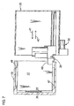
- FIG. 1 is a plan view of one embodiment of a hard disk drive storage system;
- FIG. 2 is a perspective view of one embodiment of a picker assembly for use with the hard disk drive storage system shown in FIG. 1;
- FIG. 3 is a perspective view of the picker assembly shown in FIG. 2 having a side member removed to show a plunge mechanism therein;
- FIGS. 4(a) through 4(c) show (a) a side elevation view, (b) a plan view, and (c) a front elevation view of one embodiment of a hard disk drive, respectively;
- FIG. 5 is a partial front view of one embodiment of a storage magazine;
- FIG. 6 is a front view of one embodiment of a data-access device; and
- FIG. 7 is a simplified, side elevation of a picker assembly adjacent a hard disk drive illustrating operation of the picker assembly according to one embodiment of the invention.
-
- A hard disk
drive storage system 10 is shown and described herein according to embodiments of the invention as it may be used to store large volumes of computer-readable data on a number ofhard disk drives 12. One or more users may link to the storage system 10 (FIG. 1) from a computer 15 (e.g., over a network, direct connection, etc.) via suitable control circuitry,(e.g., controller 19). The hard diskdrive storage system 10 may comprise alibrary 14 having a number of storage devices 16 (e.g., storage magazines) and at least one data-access device 18 mounted therein. Thestorage devices 16 and the data-access device 18 may be arranged in any suitable configuration, such as the generally U-shaped configuration shown in FIG. 1. - It is noted that although the
library 12 is shown with thestorage devices 16 and the data-access device 18 arranged in a particular configuration in FIG. 1, other suitable configurations are also contemplated as being within the scope of the invention. In addition, the number ofstorage devices 16 and data-access devices 18 provided in thelibrary 12 may depend upon various design considerations. Such considerations may include, but are not limited to, the frequency with which data is accessed. Other considerations may include the physical dimensions of thelibrary 12. - The
library 12 may also be provided with apicker assembly 28. Generally, thepicker assembly 28 is adapted to engage one of thehard disk drives 12, to withdraw the hard disk drive 12 (e.g., from one of the storage devices 16), to transport thehard disk drive 12 within thelibrary 12, and to eject thedata cartridge 20 at the intended destination (e.g., the data-access device 18). - A
guide system 24 may be mounted in thelibrary 14 and defines adisplacement path 26 adjacent thestorage devices 16 and the data-access device 18. In one embodiment, theguide system 24 may comprise a rail having a gear track mounted thereto. However, other embodiments of theguide system 24 are also contemplated as being within the scope of the invention and may be readily provided by one skilled in the art after having become familiar with the teachings of the present invention. - The
picker assembly 28 is operatively associated with theguide system 24 and is movable along thedisplacement path 26 to access thehard disk drives 12 in thelibrary 14. For example, thepicker assembly 28 may comprise anactuator assembly 30 having a drive motor operatively associated with a gear assembly. The gear assembly may engage the gear track on theguide system 24 and move thepicker assembly 28 on theguide system 24 in thelibrary 14. - A
suitable controller 19 is operatively associated with thepicker assembly 28 to transport thehard disk drives 12 within thelibrary 14, for example, between the data-access device 18 and thestorage devices 16. For purposes of illustration, thepicker assembly 28 is shown inpositions picker assembly 28 is shown positioned adjacent thestorage devices 16 atpositions access device 18 at position 17'. - One embodiment of a
picker assembly 28 that may be used according to the teachings of the invention is shown in more detail in FIG. 2, and is also shown in FIG. 3 with a side panel 32 removed therefrom. Thepicker assembly 28 may comprise ahousing 34 that defines acavity 36 sized to receive thehard disk drive 12. A plunge mechanism or "thumb assembly" 38 is slidably mounted to thehousing 34 so that thethumb assembly 38 may be moved toward and away from thecartridge access end 40 of thehousing 34, generally in the directions indicated byarrows - It is noted that a wide range of other picker assemblies, now known or that may be developed in the future, are also contemplated as being within the scope of the invention. Consequently, the present invention should not be regarded as being limited to use with the
particular picker assembly 28 shown and described herein. - An embodiment of one of the
hard disk drives 12 that may be provided for use with the hard diskdrive storage system 10 of the present invention is shown in more detail in FIG. 4(a) through FIG. 4(c). Thehard disk drive 12 may comprise ahousing 44. One ormore guide members housing 44 of thehard disk drive 12. - The
guide members storage device 16 to align thehard disk drive 12 when it is being inserted and withdrawn therefrom. Accordingly, thehard disk drive 12 may be readily inserted in and withdrawn from thestorage device 16 without binding. - An embodiment of the
storage device 16 is shown in FIG. 5, wherein the storage device is a storage magazine. According to such an embodiment, thestorage device 16 may comprise ahousing 51 having a number ofstorage chambers 50 formed therein, each sized to receive at least one of the hard disk drives 12. In one preferred embodiment, thestorage device 16 is removable from thelibrary 14. According to such an embodiment, one of thestorage devices 16 may be readily removed and replaced with anotherstorage device 16. - As noted above, the
storage device 16 may compriseguides 52 that cooperate with theguide members guides 52 may comprise recesses or channels that are formed in thehousing 51. Alternatively, theguides 52 may comprise a rail (e.g., a cylinder or rod). Of course, theguides 52 may be any suitable shape so as to cooperate with theguide member guide members guides 52 to guide thehard disk drive 12 into thestorage chamber 50 formed therein. - The
guide members hard disk drive 12. For example, theguide members hard disk drive 12. In such an embodiment, the mating guides 52, 56 may be provided on the sidewalls or partitions in thestorage device 16 and the data-access device 18. - Although the
guide members guide members guide members guide members guide members storage devices 16 and the data-access device 18. - The
hard disk drive 12 may also comprise aconnector 22 mounted to thehousing 44, as shown in FIG. 4(a) through FIG. 4(b). Theconnector 22 provides a link from thehard disk drive 12 to the data-access device 18 (e.g., mating connector 20). Theconnectors 20 on the data-access device 18 may be linked to acontroller 19 or directly to the user's computer (e.g., over a network). Accordingly, thehard disk drive 12 may be linked to the user's computer when thehard disk drive 12 is connected to the data-access device 18. - The
connector 22 may be any suitable connector. In one embodiment, theconnector 22 may comprise multiple connections or pins, including pins for data transfer, power, and ground. In addition, theconnector 22 may be a "hot swappable" connector so that thehard disk drive 12 can be readily connected without having to power down the data-access device 18. For example, theconnector 22 may be a readily-available single connector attachment (SCA) such as those used in RAID storage systems. SCA connectors provide the conventional 68-pin data connection, 4-pin power connection, and configuration jumpers on a single 80-pin connector. However, it is understood that other embodiments of theconnector 22 are also contemplated as being within the scope of the invention. - The
hard disk drive 12 may also comprise abracket member 48 mounted to (or integrally formed as part of) thehousing 44. Thebracket member 48 cooperates with thethumb assembly 38 on thepicker assembly 28 so that thethumb assembly 38 engages the bracket member to withdraw thehard disk drive 12 from the data-access device 18 and thestorage device 16. However, other embodiments are also contemplated as being within the scope of the present invention. For example, thebracket member 48 may instead be a notch formed in thehousing 44 of thehard disk drive 12 that cooperates with thethumb assembly 38 on thepicker assembly 28. Where thepicker assembly 28 comprises an alternative retrieval mechanism, a suitable alternative to thebracket member 48 may also be provided to cooperate therewith. - Optionally, the
hard disk drive 12 may be provided with machine-readable indicia 49 (e.g., a bar code label). It is understood that the machine-readable indicia 49 may comprise any suitable indicia, and is not limited to the bar code label shown and described herein. For example, the machine-readable indicia 49 may comprise a transponder. In any event, the machine-readable indicia 49 may be read with a suitable reader and control circuitry and used to identify thedata cartridges 12 in thelibrary 14. For example, where the machine-readable indicia 49 is a bar code label, a bar code scanner may be provided on thepicker assembly 28 so that the bar code labels can be read from the hard disk drives 12 as thepicker assembly 28 is moved along thedisplacement path 26 in thelibrary 14. Alternatively, where the machine-readable indicia is a transponder, inductive readers may be provided adjacent the transponder in each thestorage devices 16 and in the data-access device 18 to activate and read the information from the transponder. - An embodiment of the data-
access device 18 is shown in more detail in FIG. 6. The data-access device 18 may comprise a backplane 58 having one ormore connectors 20 mounted thereto. The number ofconnectors 20 mounted on the backplane may vary according to design considerations. For example,more connectors 20 provided on the backplane 58 allow more hard disk drives 12 to be simultaneously accessed. - The
connectors 20 are each linked to a power source (not shown) which provides electrical power to thehard disk drive 12 when it is linked to theconnector 20 at the data-access device 18. Theconnectors 20 also provide a data transfer connection (e.g., through control circuitry 19) that can be used to perform the read/write operations requested by the user(s). - The data-
access device 18 may also comprise ahousing 54. Thehousing 54 may be manufactured similarly to thehousing 46 of thestorage device 16. Indeed, in some embodiments the data-access device 18 may be removable from the library 14 (e.g., so that it can be easily replaced). - The
guides 56 function similarly to theguides 52 in thestorage devices 16 to align thehard disk drive 12 when it is inserted therein. In addition, theguides 56 align theconnector 22 on thehard disk drive 12 with theconnector 20 mounted on the backplane 58 of the data-access device 18 so that theconnectors guides 56 may be any suitable shape to cooperate with theguide member - The hard disk
drive storage system 10 may be operated as follows, according to one embodiment of the invention. When a user connected to the hard disk drive storage system 10 (e.g., via a networked computer) requests a read/write operation, the controller (not shown) signals thepicker assembly 28 to retrieve one of the hard disk drives 12 from one of thestorage devices 16. - The
picker assembly 28 is moved along thedisplacement path 26 on thepositioning rail 24 so that it is adjacent the selecteddata cartridge 12 in thestorage device 16. Although a data-access device 18 is shown in FIG. 7, the operation of thepicker assembly 28 to retrieve one of the hard disk drives 12 from thestorage device 16 is similar for purposes of illustration. Once thepicker assembly 28 is properly positioned in thelibrary 14, theplunge mechanism 38 is moved in the direction ofarrow 41 until it engages thehard disk drive 12. The arrangement of theplunge mechanism 38 is such that it engages thebracket member 48 on thehard disk drive 12 when theplunge mechanism 38 is at or near its fully-extended position. - After the
hard disk drive 12 has been engaged by theplunge mechanism 38, theplunge mechanism 38 reverses direction, generally as shown byarrow 42 in FIG. 7. Accordingly, the engagedhard disk drive 12 is withdrawn from thestorage device 16 and is received in the cartridge-receivingcavity 36 defined by thehousing 40 of thepicker assembly 28. Theplunge mechanism 38 continues to retract until thehard disk drive 12 is received within the cartridge-receivingcavity 36 of thepicker assembly 28 by an amount sufficient to allow thepicker assembly 28 to move to another location in thelibrary 14. - Once the
hard disk drive 12 has been retrieved, thepicker assembly 28 is moved to the data-access device 18. Thepicker assembly 28 then ejects thehard disk drive 12 by moving theplunge mechanism 38 in the direction ofarrow 41, as shown in FIG. 7. Theguide members hard disk drive 12 cooperate with theguides 56 formed in the data-access device 18 to align thehard disk drive 12 therein. Theplunge mechanism 38 continues to move in the direction ofarrow 41 as theconnector 22 on thehard disk drive 12 contacts theconnector 20 on the backplane 58 of the data-access device 18 and then links thereto (e.g., by pressing together) so that thehard disk drive 12 is ready for the read/write operation. - During the read/write operation, the
picker assembly 28 may be used to retrieve and/or return other hard disk drives 12 in thestorage system 10. Following the read/write operation, thepicker assembly 28 may be returned to the data-access device 18 and positioned adjacent the hard disk drive 12 (i.e., when it has been moved elsewhere in the library 14). Thepicker assembly 28 may then be operated to engage thehard disk drive 12 from the data-access device 18, as previously described. As thehard disk drive 12 is being withdrawn from the data-access device 18, theconnectors plunge mechanism 38 continues to retract until thehard disk drive 12 is received within the cartridge-receivingcavity 36 of thepicker assembly 28 by an amount sufficient to allow thepicker assembly 28 to move to another location in thelibrary 14. Thepicker assembly 28 may then be operated to return thehard disk drive 12 to thestorage device 16. - It is readily apparent that the hard disk drives 12 for use with the hard disk
drive storage system 10 of the present invention provide the users with fast access to their data. Also advantageously, the hard disk drives 12 are physically disconnected when not in use, reducing wear and tear and/or permanent damage or data loss that may occur if the hard disk drives 12 were always connected. In addition, the hard diskdrive storage system 10 requires less cabling than an "always-connected" system.
Claims (10)
- A hard disk drive storage system (10), comprising:a library (14);at least one storage device (16) mounted in said library;at least one connector (20) mounted in said library;at least one hard disk drive (12) receivable in said at least one storage device and alternately receivable adjacent said at least one connector; anda picker assembly (28) movably mounted in said library, said picker assembly delivering said at least one hard disk drive between said at least one storage device and said at least one connector.
- The storage system (10) of claim 1, wherein said picker assembly (28) is operable to connect a mating connector (22) of said hard disk drive (12) to said at least one connector (20).
- The storage system (10) of claim 1, wherein said picker assembly (28) is operable to disconnect a mating connector (22) of said hard disk drive (12) from said at least one connector (20).
- The storage system (10) of claim 1, further comprising a data-access device (18) having said at least one connector (20) mounted thereto.
- The storage system (10) of claim 1, further comprising at least one guide member (46, 47) mounted to each of said at least one hard disk drive (12).
- The storage system (10) of claim 5, further comprising a storage device guide (52), said at least one guide member (46, 47) cooperating with said storage device guide to align said hard disk drive (12) in said at least one storage device (16).
- The storage system (10) of claim 5, further comprising a connector guide (56), said at least one guide member (46, 47) mounted to said at least one hard disk drive (12) cooperating with said connector guide to align said at least one hard disk drive with said at least one connector (20).
- A method for accessing data from a plurality of hard disk drives (12) in a storage system (10), comprising:storing the plurality of hard disk drives in the storage system;transporting one of the plurality of hard disk drives to a connector (20) in the storage system;connecting the transported hard disk drive to the connector for a read/write operation; anddisconnecting the connected hard disk drive from the connector following the read/write operation.
- The method of claim 8, further comprising providing electrical power to the transported hard disk drive (12) after connecting the transported hard disk drive to the connector (20).
- The method of claim 8, further comprising providing a data connection to the transported hard disk drive (12) after connecting the transported hard disk drive to the connector (20).
Applications Claiming Priority (2)
| Application Number | Priority Date | Filing Date | Title |
|---|---|---|---|
| US303415 | 1989-01-30 | ||
| US10/303,415 US6909570B2 (en) | 2002-11-25 | 2002-11-25 | Hard disk drive storage system |
Publications (2)
| Publication Number | Publication Date |
|---|---|
| EP1422713A2 true EP1422713A2 (en) | 2004-05-26 |
| EP1422713A3 EP1422713A3 (en) | 2005-12-28 |
Family
ID=32229929
Family Applications (1)
| Application Number | Title | Priority Date | Filing Date |
|---|---|---|---|
| EP03013055A Withdrawn EP1422713A3 (en) | 2002-11-25 | 2003-06-10 | Hard disk drive storage system |
Country Status (3)
| Country | Link |
|---|---|
| US (1) | US6909570B2 (en) |
| EP (1) | EP1422713A3 (en) |
| JP (1) | JP2004178791A (en) |
Cited By (16)
| Publication number | Priority date | Publication date | Assignee | Title |
|---|---|---|---|---|
| EP1531467A2 (en) * | 2003-10-31 | 2005-05-18 | Tandberg Data ASA | Configurable storage system with swappable tape magazines and hard-disk magazines |
| EP1850932A2 (en) * | 2005-02-04 | 2007-11-07 | Multimedia Games Inc. | Configurable gaming machine and method for configuring games in a gaming machine |
| DE102007011714A1 (en) * | 2007-03-09 | 2008-09-11 | Fujitsu Siemens Computers Gmbh | Memory plug-in component for server rack, has freely accessible front side with memory duct for receiving drive, which is arranged in inner area of memory plug-in component |
| WO2009079449A2 (en) * | 2007-12-18 | 2009-06-25 | Teradyne, Inc. | Disk drive testing |
| US8687349B2 (en) | 2010-07-21 | 2014-04-01 | Teradyne, Inc. | Bulk transfer of storage devices using manual loading |
| US9779780B2 (en) | 2010-06-17 | 2017-10-03 | Teradyne, Inc. | Damping vibrations within storage device testing systems |
| US10725091B2 (en) | 2017-08-28 | 2020-07-28 | Teradyne, Inc. | Automated test system having multiple stages |
| US10775408B2 (en) | 2018-08-20 | 2020-09-15 | Teradyne, Inc. | System for testing devices inside of carriers |
| US10845410B2 (en) | 2017-08-28 | 2020-11-24 | Teradyne, Inc. | Automated test system having orthogonal robots |
| US10948534B2 (en) | 2017-08-28 | 2021-03-16 | Teradyne, Inc. | Automated test system employing robotics |
| US10983145B2 (en) | 2018-04-24 | 2021-04-20 | Teradyne, Inc. | System for testing devices inside of carriers |
| US11226390B2 (en) | 2017-08-28 | 2022-01-18 | Teradyne, Inc. | Calibration process for an automated test system |
| US11754596B2 (en) | 2020-10-22 | 2023-09-12 | Teradyne, Inc. | Test site configuration in an automated test system |
| US11754622B2 (en) | 2020-10-22 | 2023-09-12 | Teradyne, Inc. | Thermal control system for an automated test system |
| US11867749B2 (en) | 2020-10-22 | 2024-01-09 | Teradyne, Inc. | Vision system for an automated test system |
| US11899042B2 (en) | 2020-10-22 | 2024-02-13 | Teradyne, Inc. | Automated test system |
Families Citing this family (24)
| Publication number | Priority date | Publication date | Assignee | Title |
|---|---|---|---|---|
| US6957291B2 (en) * | 2001-03-29 | 2005-10-18 | Quantum Corporation | Removable disk storage array emulating tape library having backup and archive capability |
| US7505261B2 (en) * | 2004-03-18 | 2009-03-17 | Hewlett-Packard Development Company, L.P. | Electrical-optical signal conversion for automated storage systems |
| US20080126214A1 (en) * | 2005-10-26 | 2008-05-29 | Ballard Curtis C | Ordering supplies from an operator control panel of storage apparatus |
| US8549912B2 (en) | 2007-12-18 | 2013-10-08 | Teradyne, Inc. | Disk drive transport, clamping and testing |
| US7945424B2 (en) | 2008-04-17 | 2011-05-17 | Teradyne, Inc. | Disk drive emulator and method of use thereof |
| US8238099B2 (en) | 2008-04-17 | 2012-08-07 | Teradyne, Inc. | Enclosed operating area for disk drive testing systems |
| US8160739B2 (en) | 2008-04-17 | 2012-04-17 | Teradyne, Inc. | Transferring storage devices within storage device testing systems |
| US8041449B2 (en) | 2008-04-17 | 2011-10-18 | Teradyne, Inc. | Bulk feeding disk drives to disk drive testing systems |
| US8305751B2 (en) | 2008-04-17 | 2012-11-06 | Teradyne, Inc. | Vibration isolation within disk drive testing systems |
| US7848106B2 (en) | 2008-04-17 | 2010-12-07 | Teradyne, Inc. | Temperature control within disk drive testing systems |
| US8095234B2 (en) | 2008-04-17 | 2012-01-10 | Teradyne, Inc. | Transferring disk drives within disk drive testing systems |
| US8117480B2 (en) | 2008-04-17 | 2012-02-14 | Teradyne, Inc. | Dependent temperature control within disk drive testing systems |
| US20090262455A1 (en) | 2008-04-17 | 2009-10-22 | Teradyne, Inc. | Temperature Control Within Disk Drive Testing Systems |
| US8102173B2 (en) | 2008-04-17 | 2012-01-24 | Teradyne, Inc. | Thermal control system for test slot of test rack for disk drive testing system with thermoelectric device and a cooling conduit |
| CN102112887B (en) | 2008-06-03 | 2015-06-10 | 泰拉丁公司 | Processing storage devices |
| US8116079B2 (en) | 2009-07-15 | 2012-02-14 | Teradyne, Inc. | Storage device testing system cooling |
| US8466699B2 (en) | 2009-07-15 | 2013-06-18 | Teradyne, Inc. | Heating storage devices in a testing system |
| US8687356B2 (en) | 2010-02-02 | 2014-04-01 | Teradyne, Inc. | Storage device testing system cooling |
| US7920380B2 (en) | 2009-07-15 | 2011-04-05 | Teradyne, Inc. | Test slot cooling system for a storage device testing system |
| US8547123B2 (en) | 2009-07-15 | 2013-10-01 | Teradyne, Inc. | Storage device testing system with a conductive heating assembly |
| US7995349B2 (en) | 2009-07-15 | 2011-08-09 | Teradyne, Inc. | Storage device temperature sensing |
| US8628239B2 (en) | 2009-07-15 | 2014-01-14 | Teradyne, Inc. | Storage device temperature sensing |
| US9001456B2 (en) | 2010-08-31 | 2015-04-07 | Teradyne, Inc. | Engaging test slots |
| US9459312B2 (en) | 2013-04-10 | 2016-10-04 | Teradyne, Inc. | Electronic assembly test system |
Citations (2)
| Publication number | Priority date | Publication date | Assignee | Title |
|---|---|---|---|---|
| EP0944076A1 (en) * | 1998-03-20 | 1999-09-22 | Hewlett-Packard Company | Mounting system for cartridge engaging mechanism |
| EP1026688A2 (en) * | 1999-02-02 | 2000-08-09 | Siemens Information and Communication Networks Inc. | Removable integrated multiple internal disk drive subsystem |
Family Cites Families (12)
| Publication number | Priority date | Publication date | Assignee | Title |
|---|---|---|---|---|
| US4453188A (en) * | 1981-04-10 | 1984-06-05 | Amlyn Corporation | Disk drive |
| US4685095A (en) * | 1984-07-11 | 1987-08-04 | Filenet Corporation | Optical storage and retrieval device |
| US5041924A (en) * | 1988-11-30 | 1991-08-20 | Quantum Corporation | Removable and transportable hard disk subsystem |
| US5235474A (en) * | 1991-10-28 | 1993-08-10 | Advanced Digital Information Corporation | Apparatus and method for automatic storage of computer data |
| US5576911A (en) * | 1994-10-25 | 1996-11-19 | Sony Corporation | Cartridge locking mechanism and interface |
| US6480350B1 (en) * | 1999-09-24 | 2002-11-12 | Michael J. Malone | Hard disk drive selector |
| US6305959B1 (en) * | 1999-12-30 | 2001-10-23 | Iomega Corporation | Electrical connector with lock |
| EP1235222A2 (en) * | 2001-02-15 | 2002-08-28 | Plasmon LMS, Inc. | System for hard disk drive library |
| US6754768B2 (en) * | 2001-04-26 | 2004-06-22 | International Business Machines Corporation | Library of hard disk drives with transparent emulating interface |
| US6512962B2 (en) * | 2001-04-26 | 2003-01-28 | International Business Machines Corporation | Cabling picker in a library of stationary memory devices |
| US6711580B2 (en) * | 2001-10-01 | 2004-03-23 | International Business Machines Corporation | Data management system, apparatus, and method to use buffered file marks |
| EP1956475A3 (en) * | 2002-02-05 | 2008-08-27 | Asaca Corporation | Data storage system |
-
2002
- 2002-11-25 US US10/303,415 patent/US6909570B2/en not_active Expired - Lifetime
-
2003
- 2003-06-10 EP EP03013055A patent/EP1422713A3/en not_active Withdrawn
- 2003-11-17 JP JP2003386120A patent/JP2004178791A/en active Pending
Patent Citations (2)
| Publication number | Priority date | Publication date | Assignee | Title |
|---|---|---|---|---|
| EP0944076A1 (en) * | 1998-03-20 | 1999-09-22 | Hewlett-Packard Company | Mounting system for cartridge engaging mechanism |
| EP1026688A2 (en) * | 1999-02-02 | 2000-08-09 | Siemens Information and Communication Networks Inc. | Removable integrated multiple internal disk drive subsystem |
Cited By (20)
| Publication number | Priority date | Publication date | Assignee | Title |
|---|---|---|---|---|
| EP1531467A2 (en) * | 2003-10-31 | 2005-05-18 | Tandberg Data ASA | Configurable storage system with swappable tape magazines and hard-disk magazines |
| EP1531467A3 (en) * | 2003-10-31 | 2007-11-21 | Tandberg Data ASA | Configurable storage system with swappable tape magazines and hard-disk magazines |
| EP1850932A2 (en) * | 2005-02-04 | 2007-11-07 | Multimedia Games Inc. | Configurable gaming machine and method for configuring games in a gaming machine |
| EP1850932A4 (en) * | 2005-02-04 | 2009-08-19 | Multimedia Games Inc | Configurable gaming machine and method for configuring games in a gaming machine |
| DE102007011714A1 (en) * | 2007-03-09 | 2008-09-11 | Fujitsu Siemens Computers Gmbh | Memory plug-in component for server rack, has freely accessible front side with memory duct for receiving drive, which is arranged in inner area of memory plug-in component |
| DE102007011714B4 (en) * | 2007-03-09 | 2009-01-08 | Fujitsu Siemens Computers Gmbh | Memory plug-in component for a server rack |
| WO2009079449A2 (en) * | 2007-12-18 | 2009-06-25 | Teradyne, Inc. | Disk drive testing |
| WO2009079449A3 (en) * | 2007-12-18 | 2009-11-05 | Teradyne, Inc. | Disk drive testing |
| US9779780B2 (en) | 2010-06-17 | 2017-10-03 | Teradyne, Inc. | Damping vibrations within storage device testing systems |
| US8687349B2 (en) | 2010-07-21 | 2014-04-01 | Teradyne, Inc. | Bulk transfer of storage devices using manual loading |
| US10725091B2 (en) | 2017-08-28 | 2020-07-28 | Teradyne, Inc. | Automated test system having multiple stages |
| US10845410B2 (en) | 2017-08-28 | 2020-11-24 | Teradyne, Inc. | Automated test system having orthogonal robots |
| US10948534B2 (en) | 2017-08-28 | 2021-03-16 | Teradyne, Inc. | Automated test system employing robotics |
| US11226390B2 (en) | 2017-08-28 | 2022-01-18 | Teradyne, Inc. | Calibration process for an automated test system |
| US10983145B2 (en) | 2018-04-24 | 2021-04-20 | Teradyne, Inc. | System for testing devices inside of carriers |
| US10775408B2 (en) | 2018-08-20 | 2020-09-15 | Teradyne, Inc. | System for testing devices inside of carriers |
| US11754596B2 (en) | 2020-10-22 | 2023-09-12 | Teradyne, Inc. | Test site configuration in an automated test system |
| US11754622B2 (en) | 2020-10-22 | 2023-09-12 | Teradyne, Inc. | Thermal control system for an automated test system |
| US11867749B2 (en) | 2020-10-22 | 2024-01-09 | Teradyne, Inc. | Vision system for an automated test system |
| US11899042B2 (en) | 2020-10-22 | 2024-02-13 | Teradyne, Inc. | Automated test system |
Also Published As
| Publication number | Publication date |
|---|---|
| US20040100716A1 (en) | 2004-05-27 |
| JP2004178791A (en) | 2004-06-24 |
| EP1422713A3 (en) | 2005-12-28 |
| US6909570B2 (en) | 2005-06-21 |
Similar Documents
| Publication | Publication Date | Title |
|---|---|---|
| US6909570B2 (en) | Hard disk drive storage system | |
| US5377121A (en) | Automated storage library having inventory at picker level | |
| US6031798A (en) | Library control of media capacity scaling and library component attributes | |
| EP0375182B1 (en) | Optical disk insertion apparatus | |
| EP0558252A1 (en) | Automated storage system with array of storage cells | |
| US5966366A (en) | Cartridge engagement system for optical disk cartridges having a positionable carriage | |
| US9053741B2 (en) | Storage cartridge and cartridge drive | |
| KR100346666B1 (en) | Retrieval of serpentine pattern data using a memory device of a tape cartridge | |
| US8868866B2 (en) | Configurable tape loader with internal hard-disk | |
| WO2013039644A1 (en) | Push-push eject disk drive chassis | |
| CN101395667A (en) | Management of data cartridges in multiple-cartridge cells in an automated data storage library | |
| EP2189982B1 (en) | Housing cell, and magazine | |
| US6532203B1 (en) | Cartridge engagement system for optical disk cartridges | |
| EP1291864B1 (en) | Transporting data cartridges | |
| JP5495283B2 (en) | Cartridge removal method | |
| US20040088482A1 (en) | Systems for storing data | |
| CN1841540B (en) | Library apparatus and hand mechanism for library apparatus | |
| WO2004006243A1 (en) | One and three quarters inch form factor tape cartridge autoloader | |
| US8179630B2 (en) | Storage slot for portable data storage cartridges | |
| GB2361349A (en) | A picker mechanism for an electronic data storage library | |
| US20100058374A1 (en) | Placement of data storage cartridges in single cartridge slots and in multi-cartridge deep slot cells of an automated data storage library | |
| US8488269B2 (en) | Library apparatus | |
| US20050105208A1 (en) | Media selection systems and methods | |
| EP1235222A2 (en) | System for hard disk drive library | |
| JP3720080B2 (en) | Cartridge delivery device |
Legal Events
| Date | Code | Title | Description |
|---|---|---|---|
| PUAI | Public reference made under article 153(3) epc to a published international application that has entered the european phase |
Free format text: ORIGINAL CODE: 0009012 |
|
| AK | Designated contracting states |
Kind code of ref document: A2 Designated state(s): AT BE BG CH CY CZ DE DK EE ES FI FR GB GR HU IE IT LI LU MC NL PT RO SE SI SK TR |
|
| AX | Request for extension of the european patent |
Extension state: AL LT LV MK |
|
| PUAL | Search report despatched |
Free format text: ORIGINAL CODE: 0009013 |
|
| AK | Designated contracting states |
Kind code of ref document: A3 Designated state(s): AT BE BG CH CY CZ DE DK EE ES FI FR GB GR HU IE IT LI LU MC NL PT RO SE SI SK TR |
|
| AX | Request for extension of the european patent |
Extension state: AL LT LV MK |
|
| RIC1 | Information provided on ipc code assigned before grant |
Ipc: 7G 11B 17/22 B Ipc: 7G 11B 20/20 A |
|
| 17P | Request for examination filed |
Effective date: 20060413 |
|
| AKX | Designation fees paid |
Designated state(s): DE FR GB |
|
| 17Q | First examination report despatched |
Effective date: 20060606 |
|
| STAA | Information on the status of an ep patent application or granted ep patent |
Free format text: STATUS: THE APPLICATION IS DEEMED TO BE WITHDRAWN |
|
| 18D | Application deemed to be withdrawn |
Effective date: 20080219 |