CROSS-REFERENCES
-
This is a continuation-in-part of application Serial No. 08/475,681, filed on June 7,
1995, which is a continuation-in-part of application Serial No. 08/441,788, filed on May 16,
1995, which is a continuation-in-part of application Serial No. 08/299,987, filed September 1,
1994, which is a continuation of application Serial No. 08/047,879, filed April 15, 1993, now
abandoned, which is a continuation of application Serial No. 07/941,863 filed on September 8,
1992, now abandoned, which is a continuation of application Serial No. 07/647,463 filed on
January 28, 1991, now abandoned.
FIELD OF THE INVENTION
-
The invention relates generally to medical equipment used in the surgical treatment of
disease, and more particularly to a system and method for medical instrument navigation by
optically tracking the positions of instruments used during surgery or other treatments in
relation to a patient's anatomy.
BACKGROUND OF THE INVENTION
-
Image guided stereotaxy is widely used in the field of neurosurgery. It involves the
quantitative determination of anatomical positions based on scan data taken from a CT, MRI
or other scanning procedures to obtain three-dimensional scan data. Typically, the image scan
data is placed in a computer to provide a three-dimensional database that may be variously
used to provide graphic information. Essentially, such information is useful in surgical
procedures and enables viewing a patient's anatomy in a graphics display.
-
The use of image guided stereotactic head frames is commonplace. For example, see
U.S. Patent No. 4,608,977 issued September 2, 1986 and entitled, System Using Computed
Tomography as for Selective Body Treatment. Such structures employ a head fixation device
typically with some form of indexing to acquire referenced data representative of scan slices
through the head. The scan data so acquired is quantified relative to the head frame to identify
individual slices. A probe or surgical instrument may then be directed to an anatomical feature
in the head by mechanical connection to the head frame based on scan data representations.
Three-dimensional scan data has been employed to relate positions in a patient's anatomy to
other structures so as to provide a composite graphics display. For example, a mechanically
linked space pointer (analogous to a pencil) attached to the end of an encoded mechanical
linkage might be directed at a patient's anatomy and its position quantified relative to the
stereotactic scan data. The space pointer might be oriented to point at an anatomical target
and so displayed using computer graphics techniques. Such apparatus has been proposed,
using an articulated space pointer with a mechanical linkage. In that regard, see an article
entitled "An Articulated Neurosurgical Navigational System Using MRI and CT Images,"
IEEE Transactions on Biomedical Engineering, Volume 35, No. 2, February 1988 (Kosugi, et
al.) incorporated by reference herein.
-
The above-described systems have at least two disadvantages of note. First, the head
frame and the articulated space pointer are mechanically connected to an apparatus used to
measure and calculate the position of the probe or pointer. Consequently, although a
relatively high number of degrees of freedom can be provided to the pointer (or other tool
coupled to the pointer), the mechanical linkage may still restrict the possible ranges of motion
available to the clinician. Furthermore, the linkages may be large and obtrusive, and can be
difficult to sterilize.
-
Second, although the apparatus tracks the position of the space pointer in relation to
the patient's anatomy, the clinician is still free to move about the patient and operate from any
desired position. This is not reflected by the data produced by the device. Accordingly,
although a "pointer's eye" view of the surgical field can be provided, if the clinician is
operating from any of various other angles, then any graphical representation of the surgical
field may be disorienting, confusing, or not representative of the "surgeon's eye" view.
Although the system's point-of-view might be selected and altered manually, this is not an
optimum solution, as it requires additional steps to be taken by the clinician or an assistant.
-
In light of the above considerations, the need for relating external treatment apparatus
or surgical viewing directions to a specific target arises in several aspects. For example, the
need arises in relation to the treatment of internal anatomical targets, specifically to position
and maintain such targets with respect to a surgical instrument such as a probe, a microscope
with a specific direction and orientation of view, or an X-ray treatment beam associated with a
large external apparatus. Thus, a need exists for methods for aligning a surgical instrument,
probe, or beam not attached by any mechanical linkage, to impact specific anatomical targets
via a path selected to avoid injury to other critical anatomical structures. A further need exists
for the capability to show the operating clinician a view of the patient's anatomy and the
surgical tool from a perspective that is natural to the clinician, and not disorienting or
confusing. Further, there is a need for an economic, compact, and wireless system and method
to track instruments in clinical applications.
SUMMARY OF THE INVENTION
-
Generally, in accordance herewith, an optical camera apparatus functions in
cooperation with a computer system and a specially configured surgical instrument. In an
embodiment of the invention, the camera system is positioned to detect a clinical field of view
and to detect index markers on a surgical instrument, a patient, and/or a surgeon. The
markers are tracked by the camera apparatus. The image scan data (such as from a CT or MR
scan of the patient's anatomy) and data specifying the position of the instrument and the
surgeon are transformed relative to the patient's anatomy and the camera coordinate system,
thereby aligning the scan data, patient position and orientation data, instrument position and
orientation data, and surgeon position and orientation data for selectable simultaneous viewing
on a computer display.
-
Various exemplary embodiments are given of the use of lines, arrays of points,
geometric patterns and figures, lines of light, and other optically detectable marker
configurations to identify the position and orientation of a surgical instrument, a patient, and a
surgeon. The disclosed embodiments have the advantage of being wireless and optically
coupled to the camera tracking system. Moreover, they can be relatively economical and
lightweight in comparison to the mechanically coupled tracking devices described in the
background section above. Once the positions of the instrument, patient, and surgeon have
been determined with respect to a common coordinate system, a simulated view of the
instrument and the patient can be provided on a display device in a manner that is comfortable
and convenient to the surgeon. In an embodiment of the invention, the simulated view is
overlaid with an actual live video display to further orient the surgeon.
BRIEF DESCRIPTION OF THE DRAWINGS
-
In the drawings, which constitute a part of this specification, embodiments are
exhibited in various forms, and are set forth specifically:
- FIGURE 1 schematically illustrates a system for optically tracking instruments
and other objects in a surgical field in accordance with the present invention;
- FIGURE 2, which includes FIGURES 2A, 2B, 2C, 2D, 2E, 2F, 2G, and 2H,
illustrates various configurations of optically detectable geometric objects and patterns
associated with objects to be tracked in accordance with the system of FIGURE 1;
- FIGURE 3, which includes FIGURES 3A, 3B, 3C, 3D, 3E, and 3F, illustrates
various optically detectable objects attached to instruments in accordance with the present
invention;
- FIGURE 4, which includes FIGURES 4A, 4B, and 4C, illustrates additional
alternative embodiments of optically detectable objects in accordance with the present
invention;
- FIGURE 5 schematically shows several combinations of graphics, video, and
reconstructed representations derived from optically tracking of a surgical field;
- FIGURE 6 schematically shows a battery-powered optically tracked instrument
for use in accordance with the present invention;
- FIGURE 7 illustrates the functions performed in the combined processing of
tracking, videos, and/or image data in a display in accordance with the present invention;
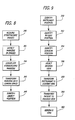
- FIGURE 8 is a flowchart showing the sequence of steps performed in tracking
an optically detectable object; and
- FIGURE 9 is a flowchart illustrating the sequence of steps performed in
generating a display when a surgical instrument, a patient, and a surgeon are all tracked by a
system in accordance with the invention.
-
DETAILED DESCRIPTION OF THE INVENTION
-
Referring initially to FIGURE 1, an embodiment of a system according to the invention
is shown schematically as including a camera system 10 that has a field of view that includes
multiple elements. The elements can include a surgical field for surgical application or a
treatment field for therapy applications. Part of the patient's body 22 may or may not be in the
camera field. Mounted to the patient within the camera field are several optically detectable
objects such as markers 24, 26, and 28, which are mounted directly on the patient, or
alternatively, identifiers 30, 32, 34, and 36 connected to a structure 38 that is rigidly
connected to the patient's body 22.
-
The markers 24, 26, and 28 or the identifiers 30, 32, 34, and 36 may be light-emitting,
light-reflecting, or otherwise optically differentially detectable geometric structures, patterns,
or elements. They may comprise, for example, light-emitting diodes ("LEDs") capable of
emitting infrared, visible, or other wavelengths of light; reflectors, such as mirrors, reflective
paint, reflective sheeting or tape, reflective dispersions, and so on. The markers or identifiers
may be fabricated in any of various shapes including discs, annular plates or rings, domes,
hemispheres, spheres, triangles, squares, cubes, diamonds, or combinations thereof. It has
been found that circular stick-down circles, domes or spheres are usable in this application.
-
The identifier 36 may include a reflective surface of triangular shape, for example, that
is detectable in spatial position and orientation by the camera system 10. In this way, the
patient's position and orientation can be detected with respect to the coordinate system of the
camera system 10; this procedure will be discussed in further detail below.
-
The camera system 10 comprises one or more cameras, each of which can be selected
from optical cameras of various known types. In FIGURE 1, three cameras are shown as part
of the camera system 10. In the disclosed embodiment, a right-mounted camera 12 and a left-mounted
camera 16 are capable of resolving two-dimensional images. The dashed lines 40
illustrate the field of view of the right-mounted camera 12; the left-mounted camera 16 has a
similar (but displaced) field of view. The cameras provide optical camera data to processor 42
related to optically detectable objects in the common field-of-view of the cameras included in
the camera system 10. For example, for the multiple-camera system 10 including cameras 12
and 16, stereoscopic or three-dimensional position data on the optically detectable object
positions in the coordinate camera system can be derived by the processor 42. Thus, in
accordance with the invention, the positions and orientations of objects within the camera
system field of view can be determined rapidly by the processor 42 and sent to a computer 44.
As will be discussed in further detail below, the computer 44 has software to represent the
positions and orientations of those objects in camera coordinates and display the objects in
various representations on a display means 46 as desired by the clinician.
-
Considering now the structure of the camera system 10, a lateral support 18 for the
cameras 12 and 16 is fixed by a coupler 20 to a rigid reference R, such as the ceiling, wall, or
floor of a room. Also shown in FIGURE 1 are light sources 50 and 52, which in the disclosed
embodiment are mounted in proximity to cameras 12 and 16, respectively. These light sources
can send light outward as for example along a path represented by a dashed line 54 to be
reflected off of a reflective optically detectable object such the marker 24 on the patient's body
22. Reflected light then returns along a path such as that represented by a dashed line 56, and
is detected by the camera 12.
-
If the marker 24 and other markers and identifiers in the field include reflective
surfaces, points, lines, or regions, then these structures can be represented as camera data in a
three-dimensional coordinate system fixed with respect to the camera system 10. For
example, in one embodiment of the invention, the light sources 50 and 52 are be pulsed
clusters ofLEDs in the infrared (IR) frequency range, and cameras 12 and 16 have selective
IR filters matched to the IR source wave length. Thereby, a good signal-to-noise of reflected
light to ambient light is achievable, and good discrimination of the markers and other
identifiers (such as markers 24, 26, and 28 and identifiers 30, 32, 34, and 36) is possible.
-
Alternatively, ambient lighting conditions can be used to enable cameras 12 and 16 to
detect the markers and identifiers. If the marker 24, for example, is a brightly colored (white,
green, red, etc.) disc, sphere, or other shape that stands out in contrast to whatever is visible in
the background, then the marker's position can be detected by the cameras. For example, if
the identifier 30 is bright white, and the surface of head clamp structure 38 is dark or black,
then the identifier 30 can be discriminated by the camera system 10.
-
As stated above, one or more cameras may be used in the camera system 10. As is
well known in the art, two or more cameras will yield stereoscopic data on objects in the
clinical field of view in relation to the camera frame of reference or in camera coordinates.
-
In an alternative embodiment of the invention, some or all of the optically detectable
identifiers (such as identifiers 30, 32, and 34) may comprise light sources themselves. For
example, the identifiers may be LEDs or other powered light sources such as lamps, possibly
enclosed in diffusing globes. The light elements of identifiers 30, 32, and 34 can be triggered
by and synchronized with cameras 12 and 16. In this embodiment, electronic shutters in the
cameras can be used to enable the camera detectors at just the time when elements 30, 32, and
34 illuminate, thereby increasing the signal-to-noise ratio.
-
Also shown in FIGURE 1 is a surgical instrument 60. The instrument can be of any
known surgical type, including but not limited to probes, cutting devices, suction tubes,
endoscopes, electronic probes, and other tools. Attached to the instrument 60 is at least one
optically detectable element 62, which can comprise various geometric structures that are
detectable and recognizable by cameras 12 and 16. For example, in the embodiment disclosed
in FIGURE 1, a rod indicator 64 is shown in a fixed relationship with a spherical indicator 66.
-
As discussed above, these indicators 64 and 66 can comprise reflective material, bright
or colored surfaces, or light-emitting elements which are detected by cameras 12 and 16. The
three-dimensional position and orientation of the element 62 can then be calculated using the
camera data processor 42 and the computer 44. The orientation and position of the
instrument 60 can thereby be determined. A calibration or pre-fixed position of the element 62
with respect to the instrument 60 may be performed before surgery or intraoperatively (see,
for example, several of the products of Radionics, Burlington, Massachusetts). As with the
other markers and indicators, if indicators 62 and 66 are light emitting, they can be connected
to the processor 42 (dashed line), and synchronized to strobing of the camera system 10.
-
In addition, light- detectable indicators 70, 72, and 74 are shown on a surgeon 76. In
the disclosed embodiment, the indicators 70, 72, and 74 are attached to a headband 78 worn
by the surgeon 76. This optical detectable array can then be tracked by the camera system 10
along with the patient's body 22 and the instrument 60. The camera data processed in the
processor 42 and assimilated in the computer 44 can thereby track in three-dimensional space
relative to the camera system 10 the positions of all elements and their relative orientations.
Thus, for example, when the indicators 70, 72, and 74 are light-emitting, the processor 42 can
be connected to the surgeon's headband 78 (dashed line) to synchronize the indicators' signals.
-
By tracking the surgeon via the headband 78, image data can be provided to the
surgeon 76 via an optical headset 80 worn by the surgeon. For example, in the disclosed
embodiment, the optical headset 80 is a binocular magnifier with built-in image-splitting
elements. Graphic data from the processor 42, originating from image scan data 48
pre-scanned from the patient, can be sent into the viewing elements of the headset 80 to
update the surgeon 76 with location data correlated to the surgeon's viewing position. For
example, from the surgeon's eye view, as represented by the position defined by indicators 70,
72, and 74, a reconstructed image of CT or MRI data taken previously and provided to the
computer 44 can be displayed via the headset 80, thereby permitting the surgeon to see a
"reconstructed" view from the direction of his physical perspective. The computer 44 can
assimilate historic image data 48 and convert it to reconstructed planar images and send that
information to a display element 46, which thereafter can be "piped" or transmitted to the
headset 80 for the surgeon's use.
-
Alternatively, the headset 80 can comprise at least one video camera 82 capable of
viewing the surgical field from the surgeon's direction. Information from the video camera 82
can be sent (via the dashed line) to the processor 42 and the computer 44 and onto the display
46. Once again, that information can then be reconstructed and displayed via a split screen
prism in the surgeon's field-of-view via his headset 80. The surgeon's view information can be
oriented in a suitable direction by the tracking of the indicators 70, 72, and 74 with the camera
system 10, as discussed above. Thus, the video information displayed in the headset 80 can be
rendered from stereotactic camera coordinates.
-
The processor 42, in one embodiment of the invention, is a dedicated processor for
electronic data from the camera system 10. The processor 42 is also capable of synchronously
controlling the light emitters 50 and 52, if needed to illuminate the optically detectable markers
or indicators on the patient 22, the head holder structure 38, the instrument 60, or the surgeon
76. Data from the processor 42 is sent to the computer 44, where it is then analyzed in three-dimensional
camera-based coordinates. Image data 48 can be in memory of the computer 44
or otherwise transferred to computer 44, as for example optical disk, magnetic tape, etc. The
visualization of camera data and image scan data (CT, MR, PET, ultrasound, etc.) is
accomplished via the display 46, which in various embodiments can be a CRT, liquid crystal
display, heads-up display, or other display device.
-
The visual image presented by the display 46 represents the position of the instrument
60 in terms of orientation, tip position, and other characteristics with respect to the image scan
data 48 in a variety of ways. For examples, see documentation for the OTS product of
Radionics, Burlington, Massachusetts. Specifically, cataloging slices, probe view, in-probe
reconstructions, three-dimensional wedge views, and other views of the instrument 60 relative
to the patient 22 can be represented on the display 46. Also, the surgeon's view, via
registration of the visual headset 80 (by identifying the indicators 70, 72, and 74 as described
above) can also be shown on the display 46. Although the instrument 60 is schematically
shown as a pointed instrument in FIGURE 1, it should be noted that an instrument 60 for use
with the present invention can be nearly any surgical instrument or device, such as a
microscope, an endoscope, a cutting instrument, an ultrasonic imaging probe, or a treatment
device such as an X-ray collimation device for a linear accelerator (LINAC). There are many
other possibilities, as well.
-
The objects in this field of view of the camera system 10 can be tracked in the three-dimensional
coordinate space of the camera system 10. The instrument 60 can be calibrated
relative to the patient 22 in a variety of ways (see the OTS Tracking System of Radionics,
Burlington, Massachusetts for examples). In one embodiment of the invention, during a
calibration procedure, the instrument 60 is touched to a plurality of fiducial markers placed on
the patient 22 (for example, the markers 24, 26, and 28), natural landmarks on the patient's
skin, surface swabbing of the patient's anatomy, a reference to real-time imaging data (for
example ultrasound, MRI, CT, etc.) in the situation where the structure 38 is connected or
associated with such an imaging apparatus, and so on. As stated, the processor 42 (or the
computer 44) uses such data in a calibration step so that the position of the instrument 60 is in
a known position and orientation relative to the patient 22 or the structure 38 affixed to the
patient 22, or even with respect to apparatus elsewhere in the room such as a linear
accelerator, an image scanner, or an apparatus on a surgeon (the headband 78, for example).
-
Referring now to FIGURE 2, various embodiments of patterns, shapes, and objects for
the optically detectable elements that can be used on, for example, the instrument 60
(FIGURE 1) or the patient 22, the surgeon 76, a microscope, or other surgical device not
shown. In FIGURE 2A, the surgical instrument 60 is rendered schematically. Although the
instrument 60 is depicted in the embodiment set forth in FIGURE 2, it should be noted that
similar or identical configurations can be used on the patient 22, the structure 38, the surgeon
76, or any other implement to be tracked. In the disclosed embodiment, the instrument 60 has
a surgical axis (dashed line 84) and a focal point, end point, isocenter, or other characteristic
point 86. It can have other independent axes such as those illustrated by dashed lines 85 and
87 to describe its orientation if it is, for example, a rigid body. In FIGURE 2A, a geometric
object 88, specifically a triangle, is attached to the instrument 60 by a connector 90. In the
illustrated embodiment, the connector 90 is a rigid coupling and is in a predetermined
relationship with the instrument 60; alternatively, it could be in an arbitrary relationship with
the instrument 60 and subject to calibration. The geometric object 88 bears a bright portion
92 (the hatched area) on its surface. The bright portion 92 of the surface of the geometric
object 88 may comprise reflective paint, reflective film, a brightly colored surface in a
particular color spectrum, or an illuminated field. The camera system 10 is represented here
only schematically, but could comprise the elements described in FIGURE 1, including
cameras, light sources, a processor, a computers, image data, and a display, among other
items. Further, it should be noted that although the geometric object 88 and its bright portion
92 are specifically described and shown as triangular in configuration, many other shapes are
possible and equally operative in the context of the invention, which is not so limited.
-
The position and orientation of the instrument 60 can be determined by tracking the
position and orientation of the geometric object 88. In various forms, the instrument 60 may
be a rigid body of complex shape. Its position, for example, may be characterized by axes
such as 84, 85, and 87, and its orientation around an axis 84 may be characterized by a
rotation angle indicated by an arrow 83. By calibrating the geometric object 88 to the
instrument 60, this rotation angle 83 and the position and orientation of the axes 84, 85, and
87 may be tracked relative to the coordinate system of the camera system 10. This can be
done by rigid body transformations which are well known to those skilled in matrix
mathematics. Thus, for example, if the instrument 60 is an endoscope or a microscope for
which the axis 84 represents a viewing direction, the characteristic point 86 is a point desired
to be viewed in the surgical field, and angle, and if the axes 85 and 87 represent the orientation
of the viewing field relative to the patient's coordinate system or the coordinate system of
image scan data, then tracking the geometric object 88 will provide position and orientation
tracking of the endoscopic or microscopic field of view.
-
Detecting the edges of the bright portion 92 in the three-dimensional coordinate
system relative to the camera system 10 enables the direction and orientation of the geometric
object 88 to be determined. By calibrating or precalibrating the orientation of the geometric
object 88 relative to the instrument 60, specifically its axis 84 and characteristic point 86
(including other axes such as axes 85 and 87, if necessary), tracking of the instrument 60 can
be accomplished (see for example the OTS Optical Tracking System of Radionics, Burlington,
Massachusetts). The camera system 10, the processor 42, and the computer 44 (FIGURE 1)
are adapted to detect edges such as a line 94 between the bright portion 92 and the remainder
of the geometric object 88, as well as the other respective edges of the triangle or geometric
shape. This may be accomplished by differential detection of the shaded area of the triangle
versus the perimeter band, which may not be of reflective, brightly colored, or illuminating
optically detectable material. Edge detection of geometric shapes can be done by well-known
segmentation or detection algorithms in the processor 42 or the computer 44. Three non-collinear
points define a plane; additional data can be used to define position and orientation
within the plane.
-
Referring now to FIGURE 2B, another type of index structure is shown. The index
structure comprises a four-sided geometric shape 96 having a shaded band 98 which may be of
reflective or bright material. Inside is a relatively dark area 100 which may be of
non-reflective material. Alternatively, the roles of the shaded band 98 and dark area 100 could
be reversed. The camera system 10 detects this object and the linear edges of the band 98 or
the dark area 100. This establishes the position and orientation of the shape 96. As with the
other index structures disclosed herein, the shape 96 is attached by a connector 102 to the
instrument 60.
-
Such a shape 96 could be easily made. The differentially reflective areas (i.e., the
shaded band 98 and the dark area 100) can be sprayed on, etched, or deposited on by a
masking process; any of these procedures would be inexpensive and lead to very sharp linear
borders between the two regions. These borders can then be detected by the camera system
10 via linear discrimination algorithms in the processor 42 and the computer 44 (FIGURE 1).
If the shape 96 is a parallelogram or a square, the orientation of the plane of the shape 96 can
easily be determined by vector cross-product calculations of the linear positions of the borders
in three-dimensional space with the edges of the object. As with all the examples in FIGURE
2, the connector 102 is optional; if the shape 96 is integrally part of the tool or instrument 60,
viz. part of its handle, then an explicit connector 102 would not be needed.
-
Referring to FIGURE 2C, the instrument 60 has attached to it an optically detectable
shape 104 in the form of a solid or a plate. On it are various geometric patterns 106, 108, and
110, which may be, for example, reflective patches or painted areas on a black background.
These structures by their respective shapes and orientation encode the position and orientation
of the shape 104. The patterns can be circles, domes, spheres, or ellipsoids which are
detectable by the camera system 10. The shape 104 may be flat or curved, according to needs.
In an embodiment of the invention, one of the patterns, e.g. pattern 110, has a more linear
structure which is distinguishable from curvilinear shapes such as shapes 106 and 108 also
identifiable by the camera system 10. In this embodiment, the pattern 108 has an annular
shape with a hole 112 in the middle to distinguish it from a dot-shaped pattern 106. The
combination can uniquely identify and locate the shape 104, and therefore the instrument 60,
in its orientation and position. The various patterns 106, 108, and 110 can be distinguished
from each other, from the background, and from other types of surgical instruments by their
reflectivity, color, position, and geometry to give a unique signature or knapping to the
instrument 60. For example, the tool could be a special forceps, and the shape 104 with its
distinguishing optical characteristics, could be known to the camera system 10 and its
associated computer system 44 to be a particular type of forceps. Similarly, other specific
tools can have different optically detectable signature structures.
-
Referring to FIGURE 2D, a flat detectable shape 114 is shown. The shape 114 has
orthogonal bar patterns 116 and 118, which could be again reflective tape on a black
background of the shape 114. These patterns are recognizable and distinguishable by
detecting the borders, such as a line 120 between the patterns 116 and 118 and the
background. Linear structures are easily detectable by camera systems and pattern recognition
software. The camera system 10 could easily scan such a geometric linear pattern in
distinguishing the linear bar patterns, thereby determining the orientation of the patterns 116
and 118 as orthogonal and in a given spatial three-dimensional position. The orientation of the
shape 114 and its position in space can be determined in the coordinates of the camera system
10. A fixed relationship between the instrument 60 and the shape 114 via a connector 122 can
then be used to identify the position and orientation of the instrument 60 in all of its
movements within the field of view of the camera system 10.
-
FIGURE 2E shows yet another embodiment of the present invention with shows a
linear rod 124 and a spherical object 126 coupled together. For instance, a reflective surface
129 on the rod 124 (shaded in the drawing) could be taped or painted onto the rod 124. On
the end of the rod, the spherical object 126 bearing reflective tape or paint is, in the disclosed
embodiment, coaxial with the painted surface 128 of the rod 124. The camera system 10 is
capable of recognizing the linear form of the rod 124 and the center of the spherical object
126. Accordingly, a detection algorithm in the computer 44 (FIGURE 1) could determine the
linear configuration and central axis of the rod 124, and the centroid point of the spherical
object 126, thereby determining a vector direction along the axis of the rod 124 and a uniquely
identified endpoint at the spherical object 126. The rod 124 and the spherical object 126 are
joined by a connector 129 to the instrument 60, thereby specifying the position and orientation
of the instrument 60 with respect to the camera system 10.
-
Referring to FIGURE 2F, another example of the present invention comprises a
longitudinal rod 130 with a reflective linear surface 132 (shaded) and an orthogonal rod 134
with two reflective segments 136 and 138 (shaded). These linear structures again are
detectable by the camera system 10, thereby determining the orientation of the plane defined
by the longitudinal rod 130 and the orthogonal rod 134. As described above, this is
information is then used to determine the orientation and movement of the instrument 60,
which is coupled to the rods 132 and 134 via a connector 139, in three-dimensional space..
-
FIGURE 2G shows yet another example of rod-like structures in a triangle 140. The
shaded linear segments 142, 144, and 146 lie at the edges of the triangle 140 and define the
plane and orientation of the triangle 140. The triangle 140 is attached to the instrument 60 by
a connector 148, and the instrument is tracked as described above.
-
Referring to FIGURE 2H, a similar V-shaped structure 150 comprising identifiable leg
segments 152 and 154 (shaded) provides a similar position and orientation vector analogous to
the previous examples.
-
FIGURE 3 presents several further embodiments of the present invention that are
useful in certain applications. In FIGURE 3A, a plate 160 or similar structure has detectable
areas 162, 164, and 166 (shaded). A connector 168 couples the plate 160 to the instrument
60. In one embodiment of the invention, the plate 160, with its identifiable multiple areas, is a
disposable sterile-packed device which can be detachably coupled to the connector 168. The
detectable areas 162, 164, and 166 can be, for example, reflective disks that are adhesively
affixed to the plate 160 in particular positions that are recognizable and indexed by the camera
system 10 in conjunction with the processor 42 and the computer 44 (FIGURE 1). The
concept of a disposable, single use, sterile-packed, optically detected index marker such as that
shown in FIGURE 3A has several advantages over non-disposable, more expensive devices.
The plate 160 can be coupled to the connector 168 in a pre-calibrated or a non-precalibrated
orientation. If calibrated, it will have a known relationship to the instrument 60 and any focal
points, features, or directions thereof. If non-precalibrated, the plate 160 could simply be
"stuck" onto the connector 168 and used in an intraoperative calibration procedure to
determine translations, rotations, and other transformations of the plate 160 and instrument 60
prior to defining the movement and relative orientation of the instrument 60. The process of
intraoperatively calibrating positions, directions, and orientations of the instrument 60 is
facilitated by an intraoperative calibration holder (not shown; see the products of Radionics,
Burlington, Massachusetts).
-
Referring to FIGURE 3B, another plate-like index structure is shown. A plate 170 is
attached to the instrument 60 by a connector 172. On the surface of the plate 170, there are
dome-shaped structures 174 and 176. In the disclosed embodiment of the invention, the
dome-shaped structures 174 and 176 comprise embedded illumination devices (e.g., LEDs).
Alternatively, the dome-shaped structures can include surface-mounted illumination devices,
or can simply be made from reflective material. The dome-shaped structures 174 and 176 are
then detectable by the camera system 10, as described above. If the dome-shaped structures
have spherical or convex surfaces, then the camera system 10 can detect their surfaces and
average the three-dimensional positions of the surface points to identify a centroid which may,
for example, be the center of a sphere or a hemisphere. Accordingly, there can be several of
these spherical or dome-shaped structures on the plate 170 in a pattern or array. The
structures can be in a linear array, on the comers of a triangle, on the comers of a square, or in
a multiple indexed array to provide position, orientation, and transformation information to a
system according to the invention.
-
Referring to FIGURE 3C, yet another plate-like index structure in accordance with the
present invention is shown. A plate 180 is attached to the instrument 60 in a similar fashion to
that described above. On the surface of the plate 180 are reflective patterns 182 and 184, here
in the form of diamonds or other multi-sided objects. Such patterns are identifiable by the
camera system 10 and its analysis system to discriminate them from other objects in the field,
just as is done in all the previous examples. For example, in the disclosed embodiment, the
patterns 182 and 184 are square or diamond-shaped patches of reflective paint or tape;
alternatively, they could be brightly colored surfaces with different colors to be detected by the
camera system 10. Multiple arrays or groups of such diamond-shaped patterns with
differential reflective and non-reflective areas are possible to facilitate discrimination by the
camera system 10. For example, a background surface 186 on the plate 180 may be of
opaque, black character so that the linear edges between the patterns 182 and 184 and that
surface 186, for example, have a sharp optical delineation. This makes it simpler for the
camera system 10 and its processor 42, and computer 44 to detect such an edge. If the edge is
straight, then detection along the lined contour can readily be performed by well-known
analysis methods. This can give precise linear directions which in turn can define the vector
and positional orientation of the entire plate 180, and thus the orientation of the instrument 60,
with high accuracy.
-
Referring now to FIGURE 3D, yet another plate-like index structure is shown. A plate
190 is shown in a somewhat triangular or trapezoidal shape. It has on it linear structures 191
and 192, which may be reflective edges or other patterns laid down or fastened to the surface
plate 190. The linear structures 191 and 192 provide contrast for optical discrimination by
being highly reflective or very brightly colored surfaces that are detectable by and analyzable
by the camera system 10, as described above. The linear borders on both sides of the
structures 191 and 192 make possible linear discrimination analysis of these surfaces and also,
by mutual information theory, an easily recognizable pattern. In this case, the pattern is a
non-parallel linear or V-shaped pattern of the elements 191 and 192. Such a V-shaped pattern
corresponds to and defines two vectors, which in turn can define the plane and orientation of
the plate 190, and thus the instrument 60.
-
In FIGURE 3E, the instrument 60 is provided with three spherical elements 193, 194,
and 195 in a linear configuration, each of which is made to be reflective or light-emitting.
Three centroids corresponding to the spherical elements 193, 194, and 195 can then be
determined, and the position and orientation of the instrument 60 follows.
-
In the embodiment of FIGURE 3F, the instrument 60 bears three spherical elements
196, 197, and 198 in a triangular configuration, each of which is reflective, light-emitting, or
otherwise optically detectable. The centroids of the three spherical elements 196, 197, and
198 are determinable by the system; the centroids define a plane that specifies the orientation
of the instrument 60.
-
Turning now to FIGURE 4, in FIGURE 4A a solid three-dimensional optically
detectable structure is attached to the instrument 60 or comprises part of the instrument 60
itself. The structure includes a rod 200 which is attached by coupler 202 to a sphere 204. The
rod 200 and the sphere 204 comprise reflective or distinctly colored material detectable by the
camera system 10. The reflective rod 200 has the advantage that from all directions it has a
similar linear shape, the edges of which are discriminated by the camera system 10 and
detected by linear edge detection. A centroid axis 206 can therefore be calculated for the rod
200 by the processor 42 and the computer 44 (FIGURE 1). The reflective sphere 204 defines
a centroid 208 which can be detected by spherical edge detection of the sphere 204 and
appropriate centroid calculation in the processor 42 and the computer 44. The combination of
the axis 206 and the centroid 208 determines the plane defined by the sphere 204 and the rod
200, and thus the orientation and position of the instrument 60.
-
In FIGURE 4B, a solid prism-shaped object 210 is coupled by a connector 212 to the
instrument 60. On the sides of the object 210, namely a right side 214 and a left side 216,
there are respective reflective areas 218 and 220 (shaded), which can be polished, painted,
reflective paint, or reflective tape surfaces. Their position and direction determine the
orientation of the object 210, and therefore by transformation the orientation and position of
the instrument 60.
-
Referring to FIGURE 4C, a solid prismoidal structure 222 has distinguishing optically
detectable markings which perform as a signature of the instrument 60 to which it is attached.
On one face of the structure 222, there is shaded area 224 having a distinct shape. On another
face, there are two separate shaded areas 226 and 228 having distinguishable size and shape
characteristics. In observing the structure 222, the camera system 10 can determine by the
size and shape characteristics of the shaded areas 224, 226, and 228 the orientation and
position of the structure 222, and thus the orientation and position of the instrument 60. As
described above, a large number of different and identifiable objects such as the structure 222
can be used to distinguish one tool from another. The detectable faces on different sides of
the structure 222 will ensure that the structure 222 is identifiable from nearly any direction of
view by the camera system 10. Patterns such as bar codes or distinguishable line or obj ect
orientations can be used to encode the structure 222 (and thereby the instrument 60), allowing
each different type of instrument to be recognizable via pattern recognition algorithms
implemented in the processor 42 and the computer 44.
-
While most of the embodiments described above (in FIGURES 2, 3, and 4) include a
connector to couple an optically detectable structure to the surgical instrument 60, it should be
noted that the objects, shapes, and patterns in the above examples can generally be built
integrally into the instrument 60 itself The very shape of the instrument may be optically
detectable and classified and tracked by the camera system 10 and other processing elements,
as described above.
-
The embodiments of FIGURES 1, 2, 3, and 4 have the advantage of providing
optically coupled, non-mechanically coupled, wireless tracking. The marker objects of
FIGURES 2, 3, and 4 can be made simply, economically, lightweight, and sterilizable or
sterilely packaged. Each embodiment has practical advantages relative to the frame-based or
mechanically-linked space pointers given as examples in the background section above.
-
FIGURE 5 illustrates the operative functionality of a system according to FIGURE 1.
The surgical instrument 60 has an optically detectable index structure 230. A dynamic
referencing head clamp 232 with index marks 234, 236, and 238 is present; the clamp 232
further includes an additional index marker 240. A processor 242 and a computer 244 convert
camera data from the camera system 10 for an image display 246, which shows a
representation of the position of the instrument 60 as a dashed line 248 relative to an
anatomical structure 250. A predetermined point on the instrument 60, such as a tip or a focal
point, is indicated relative to the anatomical structure 250 as a point 252. Examples of such
coordinated display of probe orientation and image data is given in the product of OTS by
Radionics, Burlington, Massachusetts.
-
The processor 242 and the computer 244 are also capable of generating a separate
representation 254 of the position of the instrument 60. The separate representation 254
displays in a two- or three-dimensional form 256 the position of the instrument 60 in
comparison to an anatomical rendering 258, along with other optional representations of
probe, anatomy, or target points such as a target point 260. In the disclosed embodiment, the
separate representation 254 is reconstructed from two-dimensional or three-dimensional image
data such as CT or MR scans taken of the patient previously or contemporaneously in a
real-time image scanner during surgery or treatment.
-
As with the system set forth in FIGURE 1, three-dimensional analysis of the position
of the instrument 60 can be accomplished by determined by the stereoscopic cameras 12 and
16, together with the processor 42 and the computer 44. This can be done based on LED or
reflective infrared light processing, or alternatively based on direct visible-light video
processing of information from the two cameras 12 and 16. It can be advantageous to provide
the cameras 12 and 16 with infrared optical filters. If the optically detectable objects used in
the system are infrared LEDs or if the cameras have pulsed infrared light sources near them,
then filtering will increase the signal-to-noise ratio of the tracking signal and reduce the effect
of any ambient light background.
-
In an alternative embodiment of the invention, a third camera 14 is provided (see also
FIGURE 1). The third camera 14 is preferably a standard video camera which views the
surgical field. The processor 42 and the computer 44 further display the view from the third
video camera 14 in an additional display 262. In this way, a direct video view of the patient
264 is available. In addition, a view of the instrument 60 (seen as an instrument image 266
with an index marker image 268) is seen from actual video.
-
A virtual extrapolation of the probe, shown as a dashed line 270 with a tip or target
point 272, can be determined from the analysis shown on the alternative representation 254.
In an embodiment of the invention, this virtual extrapolation is overlaid directly onto the
additional display 262 so that direct comparison of the reconstructed three-dimensional
navigation image of the alternative representation 254 can be compared to an actual video
image on the additional display 262. Correspondence and registration between a
reconstructed image and an actual image in this way confirms the correctness of the probe
orientation, and consequently the virtual position of unseen elements such as probe tip and
probe position, for example in the depths of the surgical wound. Thus, a hybrid of
reconstructed stereoscopic tracking by one set of cameras (e.g., the cameras 12 and 16) can be
displayed and coordinated with respect to video imaging from another set of cameras (e.g., the
video camera 14).
-
All cameras may be of the visible video type, or some may be filtered infrared (or other
spectral filtered types) used with others of the visible video type. For example, in the
embodiment of FIGURE 5, the cameras 12 and 16 used for tracking are infrared filtered
cameras; while the additional video camera 14 observes the visual spectrum. Accordingly,
offering a comparison between the views provided by the separate cameras is a useful quality
assurance check of the integrity of the entire tracking system.
-
Referring now to FIGURE 6, another embodiment of the present invention involves a
battery-powered optically detectable index structure 280 associated with an instrument 282.
A camera system 284 comprises three cameras 286, 288, and 290, which in the disclosed
embodiment are linear infrared CCD cameras (see for example the IGT product, Boulder,
Colorado). Data signals are processed by a processor 292, and these can be sent to a
computer system, as described above (see FIGURE 1). The instrument 282 is shown
generically; the optical index structure 280 comprises LED emitters 294, 296, and 298 which
in a preferred embodiment are of an infrared-emitting type. The emitters 294, 296, and 298
define a plane of light which can be transformed to specify the position of the instrument 282
to which they are attached. The emitters 294, 296, and 298 are coupled to a circuit 300 which
distributes energy to the LEDs for their illumination. The circuit 300 controls the sequence
and synchronization of LED lighting. A battery 302 is provided to supply power to the circuit
300 and to the emitters 294, 296, and 298.
-
In an embodiment of the invention, the LED emitters 294, 296, and 298 are flashed in
a coded sequence controlled by the circuit 300 that is detectable by the processor 292 so as to
recognize the instrument 282 and the index structure 280. Alternatively, the pattern of
positions of the emitters 294, 296, and 298 can be used to allow the processor 292 to
discriminate what specific instrument 282 is being used.
-
As an alternative, a coding scheme can be sent from a transmitter 304 to a receiver 306
coupled to the instrument 282. The receiver 306 accepts light or radio wave signals from the
transmitter 304, which is connected to the processor 292. A synchronization signal
representative of the shutter operation from the cameras 286, 288, and 290 is sent via the
transmitter 304 (as shown by a dashed line 308) to the receiver 306. The receiver 306 and the
circuit 300 then cause the sequential flashing of the emitters 294, 296, and 298 detected by the
cameras. An optional return signal (represented by a dashed line 310) from the receiver 306
to the transmitter 304 can be used to confirm the synchronization of the emitters to the
cameras.
-
Again a patient 312 may be in the surgical field with attached optically detectable index
elements 314, 316, and 318, plus others as described above. These light emitters may also be
battery powered or wire powered from either batteries or another source.
-
The LED emitters 294, 296, and 298 do not consume much power if they are flashed
intermittently, and thus the battery 302 comprises a standard type of battery, such as one that
might be used to operate a flashlight, camera, or other small appliance. Such batteries can
easily be replaced or sterilized at the time of surgery. The use of batteries in a surgical
instrument is advantageous in that the system is wireless and mechanically de-coupled from the
camera system and its processor.
-
Referring again to FIGURE 1, light sources may be used near to the cameras to
produce reflected light from reflecting optically-detectable objects. In various embodiments of
the invention, the optically detectable objects can alternatively have bright, colored, or shiny
surfaces or have contrasting patterns of light and dark or alternately colored shapes and
patterns to be detectable by cameras in ambient light. By arranging the ambient light to shine
appropriately on a surgical, diagnostic, or therapeutic setting, objects can be recognized
directly by the camera system 10 as shown in FIGURE 1. However, the use of additional
lights near the cameras can enhance the reflection from optically detectable objects in certain
clinical settings where ambient light may not be sufficient, or where high degrees of light
contrast, such as from surgical head holders, microscope lights, or operating theatre lights may
cause difficulty in discriminating light levels from the detectable objects. Thus, various
illumination possibilities can easily be devised in accordance with the present invention to
facilitate detection and data processing of the camera and video information to suit the clinical
context.
-
Referring now to FIGURE 7, a block diagram is provided to illustrate the relationship
among the various functional steps performed by a system according to the invention. A
camera and light reflection processing function (block 320) specifies that the camera system 10
(FIGURE 1) detects an instrument with an optically detectable object attached to it. This is
done with a camera system as described above, wherein camera data from infrared filtered
cameras of various kinds and/or video cameras is provided to a pattern data processing
function (block 322). The pattern data processing function 322 receives data from the camera
and light reflection processing function 320, allowing the instrument is recognized by pattern
recognition algorithms operating on stereoscopic data received from the camera system 10.
The nature of the instrument can also be recognized by way of time or geometric sequencing
or arrangements of light-emitting or light reflecting objects or patterns on the instrument, as
described above.
-
As part of cameras, as shown for example in FIGURE 1 and FIGURE 5, a visible
video camera may also be used in combination with filtered or unfiltered cameras as a
confirmational step. A video processing function (block 324) is provided to carry out the
reception and processing of such visible video data. The output data from such video
processing is sent to a computer processing function (block 326), along with the instrument
tracking data from the pattern data processing function 322. The computer processing
function 326 may also accept image scan data which is either taken prior to operation or
contemporaneously during the operation, as illustrated by an image data processing function
(block 328). The computer processing function 326 can then combine or merge a combination
of pattern recognition and tracking data (from the pattern data processing function 322), the
visible video data (from the video processing function 324), and image scan data (from the
image data processing function 328), so as to display it in various forms via a display function
(block 330).
-
Various examples of combination displays have been described in connection with
FIGURE 5. A useful quality assurance check would be, for example, to overlay visible video
data onto the combined representations of the image scan data and of the surgical instrument
as it moves relative to the anatomy. The video data shows in real time the position of an
instrument relative to the anatomy, or the relative position of instruments relative to each
other, within the field of surgical view. Seen on a display, a rendering of the reconstructed
position of a surgical instrument relative to the overlaid anatomy, or compared side-by-side to
the actual visible video view of the instrument relative to the anatomy, is a strong
confirmational step to show that the tracking is being done properly. In certain clinical
situations such as surgery, X-ray treatment on a treatment planning machine such as a linear
accelerator, or patient positioning on a diagnostic machine, such a confirmational step could
be very important. Thus, the process of FIGURE 7 can apply to camera and video detection
in the surgical setting, a diagnostic suite, or in connection with treatment planning process and
instrumentation. Use, for example, together with a real time diagnostic or intraoperative
imaging machine such as a CT, MR, PET, X-ray, or other scanner would be another context
for the process in FIGURE 7.
-
Also shown in FIGURE 7 is a patient registration data processing function (block
332), which represents the step of registering or calibrating instrumentation or apparatus
relative to a patient, prior to performing a procedure with the tracked instrument. The
registration step may be predetermined or determined during the clinical setting in a variety of
ways, as described above.
-
The steps performed in tracking an object (for example, the instrument 60, the patient
22, or the surgeon 76) according to the invention are set forth in FIGURE 8. First, a set of
multiple camera images (stereoscopic images for the case of two or more two-dimensional
cameras) is acquired (step 340) from the camera system 10 (FIGURE 1). Any markers
present in the stereoscopic images are then detected (step 342) as described above. For
example, when two two-dimensional CCD cameras are used, there are two frames in a set of
stereoscopic images, namely a left frame (from the left camera 16) and a right frame (from the
right camera 12). The detected markers will appear in slightly different positions in the two
frames, so the positions are then correlated (step 344). The difference in a marker's position
between the two frames is used to determine depth (i.e., distance from the camera system 10)
in three dimensions. It should be noted that more than two cameras may be used in the
present invention; the additional cameras can be used to verify the stereoscopic images or to
provide further accuracy or definition.
-
After the markers have been correlated between the stereoscopic frames, the images
are further processed to determine the positions of the markers in three-dimensional space by
transforming the markers (step 346) into a coordinate system defined by the camera system
10. As described above, this step is performed in varying ways depending on the nature of the
markers in the field of view. For example, a spherical marker will define a centroid, while a
rod-shaped or flat marker will define an axis. Accordingly, the unique set of centroids, axes,
and other characteristics in the coordinate system of the cameras can be used to identify the
position of the object being tracked (step 348). This information is used in the operation of
the system as described below.
-
FIGURE 9 illustrates, in one exemplary embodiment, how the various objects are
tracked by the system to generate one or more displays, as described above. First, the location
of the surgical instrument 60 (FIGURE 1) is identified with respect to the camera system 10,
as described in conjunction with FIGURE 8. A set of coordinates is generated thereby. Those
coordinates specify the position of the instrument 60, and further specify a transformation
between the coordinate system of the camera system 10 and a coordinate system associated
with the instrument. This may involve, for example, index point registrations from the
patient's physical anatomy to image scan data, as described previously. Next, or concurrently,
the location of the patient 22 is identified (step 352) with respect to the camera system 10.
Again, the coordinates specify the position of the patient 22 and a coordinate transformation
between the camera system and the patient. Finally, or concurrently, the location of the
surgeon 76 is identified (step 354), as above.
-
With all of the positional data having been generated, a desired view is selected (step
356) by the surgeon or other operator. Several possible views have been described above, but
there are alternatives. For example, a "surgeon's eye" view is possible by transforming the
instrument position and the patient position into the surgeon's coordinate system. An
"instrument's eye" view is possible by transforming the patient position into the instrument's
coordinate system. A patient-centered system is possible by transforming the instrument
position into the patient's coordinate system. These transformations involve simple matrix
manipulation and trigonometric calculations; they would be well-known to a person of
ordinary skill in the mathematical arts.
-
The desired transformations of the instrument position (step 358) and the patient
position (step 360) are then performed. A display is generated (step 362) based on the
transformed positions (see FIGURE 5). As described above, the display can comprise only a
reproduction of the instrument in relation to a reproduction of the patient's anatomical
structures (for example, based on reconstructions from image scan data from CT, MR, or
other types of scans), or can include an overlaid video view from a video camera 14 on the
camera system 10 or a video camera 82 on the surgeon 76. Moreover, the patient's anatomical
data can be manipulated in various ways well known in the art to provide slice, cutaway, or
contour views, among others. Moreover, further coordinate transformations can optionally be
provided to allow operator control over the views on the display, for example to slightly
displace a view from a true "instrument's eye" view.
-
Steps 350-362 are repeated as necessary to update the display with the various object
positions in real time or close to real time.
-
Forms and embodiments of optical object tracking systems and methods are provided
involving various geometries, detection methods, pattern recognition methods, display
methods, systems components, and process steps. However, it should be recognized that
other forms varying from the embodiments specifically set forth herein may be used as
variations of the above examples in accordance with the present invention. In particular, it
should be noted that although various functional components have been set forth and
described herein, many of these functional components can be integrated (into a single general-purpose
digital computer, for example), or performed by separate processing devices; any such
embodiment is intended to be within the scope of the invention. Moreover, although
sequences of process steps are set forth herein as though performed in a certain order, it is
recognized that the invention will be equally operative if the steps are rearranged or otherwise
performed in a different order. In addition, it has been noted that certain steps are optional,
such as identifying the surgeon's position (step 354) if it is not desired to track the surgeon.
-
In view of these considerations, as would be apparent by persons skilled in the art, the
implementation of a system in accordance with the invention should be considered broadly and
with respect to the claims set forth below.