EP1403660A1 - Vehicle surroundings monitoring apparatus and traveling control system incorporating the apparatus - Google Patents
Vehicle surroundings monitoring apparatus and traveling control system incorporating the apparatus Download PDFInfo
- Publication number
- EP1403660A1 EP1403660A1 EP20030021469 EP03021469A EP1403660A1 EP 1403660 A1 EP1403660 A1 EP 1403660A1 EP 20030021469 EP20030021469 EP 20030021469 EP 03021469 A EP03021469 A EP 03021469A EP 1403660 A1 EP1403660 A1 EP 1403660A1
- Authority
- EP
- European Patent Office
- Prior art keywords
- solid
- solid objects
- fusion
- vehicle
- reliability
- Prior art date
- Legal status (The legal status is an assumption and is not a legal conclusion. Google has not performed a legal analysis and makes no representation as to the accuracy of the status listed.)
- Granted
Links
- 238000012544 monitoring process Methods 0.000 title claims abstract description 35
- 239000007787 solid Substances 0.000 claims abstract description 231
- 230000004927 fusion Effects 0.000 claims abstract description 101
- 238000003384 imaging method Methods 0.000 claims description 3
- 238000000034 method Methods 0.000 description 11
- 239000000284 extract Substances 0.000 description 4
- 238000010586 diagram Methods 0.000 description 3
- 238000005516 engineering process Methods 0.000 description 2
- 239000003550 marker Substances 0.000 description 2
- 230000003044 adaptive effect Effects 0.000 description 1
- 230000002411 adverse Effects 0.000 description 1
- 230000001174 ascending effect Effects 0.000 description 1
- 230000005540 biological transmission Effects 0.000 description 1
- 238000001514 detection method Methods 0.000 description 1
Images


Classifications
-
- B—PERFORMING OPERATIONS; TRANSPORTING
- B60—VEHICLES IN GENERAL
- B60K—ARRANGEMENT OR MOUNTING OF PROPULSION UNITS OR OF TRANSMISSIONS IN VEHICLES; ARRANGEMENT OR MOUNTING OF PLURAL DIVERSE PRIME-MOVERS IN VEHICLES; AUXILIARY DRIVES FOR VEHICLES; INSTRUMENTATION OR DASHBOARDS FOR VEHICLES; ARRANGEMENTS IN CONNECTION WITH COOLING, AIR INTAKE, GAS EXHAUST OR FUEL SUPPLY OF PROPULSION UNITS IN VEHICLES
- B60K31/00—Vehicle fittings, acting on a single sub-unit only, for automatically controlling vehicle speed, i.e. preventing speed from exceeding an arbitrarily established velocity or maintaining speed at a particular velocity, as selected by the vehicle operator
- B60K31/0008—Vehicle fittings, acting on a single sub-unit only, for automatically controlling vehicle speed, i.e. preventing speed from exceeding an arbitrarily established velocity or maintaining speed at a particular velocity, as selected by the vehicle operator including means for detecting potential obstacles in vehicle path
Definitions
- the present invention relates to a vehicle surroundings monitoring apparatus employing together a monitoring technique on the base of images and a monitoring technique using radar data and a traveling control system incorporating the apparatus.
- Japanese Patent Application Laid-open No. Toku-Kai-Hei 6-230115 discloses a technology in which the intervehicle distance between an own vehicle and a preceding vehicle is obtained in two ways, one is processing images taken by a stereoscopic camera and the other is directly detecting the distance by a millimeter wave radar. The reliability of the intervehicle distances obtained in the respective ways is investigated based on exterior circumstances and the like and either of the intervehicle distances is selected based on the reliability.
- Toku-Kai-Hei 6-230115 has a disadvantage that since the respective reliabilities of stereoscopic camera and millimeter wave radar are judged simply on the basis of the external circumstances, a proper intervehicle distance is rejected and wrong data are adopted in some cases.
- a vehicle surroundings monitoring apparatus for monitoring exterior circumstances and detecting a preceding vehicle traveling ahead of an own vehicle, comprises image solid object detecting means for detecting image solid objects based on image information outputted from a CCD camera, millimeter wave solid obj ect detecting means for detecting millimeter wave solid objects based on signals outputted from a millimeter wave radar, fusion solid object establishing means for establishing fusion solid objects composed of single image solid objects, single millimeter wave solid objects and a combination of the image solid obj ects and the millimeter wave solid obj ects by fusing the image solid objects and the millimeter wave solid objects, first reliability judging means for judging a degree of reliability of the fusion solid objects based on a detecting situation of the respective fusion solid objects by the image solid object detecting means, second reliability judging means for judging a degree of reliability of the fusion solid objects based on a detecting situation of the respective fusion solid objects by the millimeter wave solid object
- reference numeral 1 denotes a vehicle (own vehicle) on which an intervehicle distance automatically adjusting system (Adaptive Cruise Control: ACC) 2 is mounted.
- the ACC system 2 is constituted by a stereoscopic camera (imaging means) 3, a millimeter wave transmitting and receiving section (radar means) 4, a vehicle surroundings monitoring apparatus 5 and a traveling control unit 6.
- imaging means imaging means
- radar means millimeter wave transmitting and receiving section
- vehicle surroundings monitoring apparatus 5 and a traveling control unit 6.
- the stereoscopic camera 3 is composed of a pair (left and right) of CCD cameras using a solid-state image component such as Charge Coupled Device and the left and right cameras are transversely mounted on a front ceiling of a passenger compartment at a specified interval of distance, respectively.
- the respective cameras take picture images of an exterior object from different view points and input image information to the vehicle surroundings monitoring apparatus 5.
- the millimeter wave transmitting and receiving section 4 provided at the front end of the own vehicle 1 transmits millimeter wave (for example radio wave having frequency 30G Hz to 100G Hz) forwardly therefrom and receives reflected millimeter wave, inputting sending and receiving data to the vehicle surroundings monitoring apparatus 5.
- millimeter wave for example radio wave having frequency 30G Hz to 100G Hz
- the vehicle surroundings monitoring apparatus 5 comprises a stereoscopic image processing section 15 (first solid object detecting means), a distance measuring section 16 (second solid object detecting means), a fusion solid object establishing section 17 (fusion solid object establishing means), an own traveling region estimating section 18 and a preceding vehicle recognizing section 19 (first and second reliability judging means and preceding vehicle selecting means).
- those sections work in a coordinate system fixed to the own vehicle 1 of the three-dimensional real space.
- the coordinate system is composed of X coordinate extending in a widthwise direction of the own vehicle 1, Y coordinate extending in a vertical direction of the own vehicle 1, Z coordinate extending in a lengthwise direction of the own vehicle 1 and an origin of the coordinate placed on the road surface directly underneath the central point of two CCD cameras forming the stereoscopic camera 3.
- the positive sides of X, Y and Z coordinates are established in a right direction, in an upward direction and in a forward direction, respectively.
- the stereoscopic image processing section 15 performs various recognitions of lane markers, side walls, solid objects and the like as follows. First, with respect to a pair of stereoscopic images taken by the stereoscopic CCD camera 4, the stereoscopic image processing section 15 obtains distance information over the entire image from the deviation amount between corresponding positions according to the principle of trianguration and forms a distance image representing three-dimensional distance distribution based on the distance information.
- the stereoscopic image processing section 15 extracts lane markers, guardrails, curbs, side walls and solid objects like vehicles by performing the known grouping process, the comparison of the distance image with three-dimensional road profile data, side wall data such as guardrails, curbs and side walls along a road and solid object data such as vehicles and other data which are stored in the memory.
- extracted lane marker data, side wall data and solid object data are denoted by different numbers for each kind of data, respectively.
- the solid object data are classified into three kinds of objects, a backward moving object moving toward the own vehicle 1, a still object in standstill and a forward moving object moving in the same direction as the own vehicle 1 based on the relationship between the relative variation of the distance from the own vehicle and the vehicle speed of the own vehicle 1.
- the stereoscopic image processing section 15 usually extracts the front or rear surface as a solid object and extracts the side surface as a side wall connected through the corner part with the solid object. Accordingly, in case where the extracted solid obj ect is a vehicle, mostly, a side wall connected through a corner part with the solid object is recognized. In case where smear or flare are recognized as a solid object by accident, there is a very small chance that a side wall comes adjacent to the solid object. Accordingly, there is a high possibility that the solid obj ect having two or more surfaces is a vehicle. In the stereoscopic image processing section 3, if the solid object is connected to the side wall through the corner part, the object is registered specially as a corner-like solid object.
- the distance measuring section 16 performs solidity recognition by processing transmitting and receiving data inputted from the millimeter wave transmitting and receiving section 4 as follows. That is, the distance measuring section 16 measures the distance from the own vehicle 1 to the target based on a time between the transmission of a radio wave and the reception of the reflected radio wave. Then, preparing a distribution diagram of distance values, if there is a portion continuously having an identical distance value in the distribution diagram, the portion is extracted and registered as a solid object.
- the distance measuring section 16 stores the data of the solid object extracted and registered in the previous cycle (this solid object will be referred to as "millimeter wave solid object” hereinafter).
- this solid object will be referred to as "detected millimeter wave solid object” hereinafter
- the coincidence is judged between the detected millimeter wave solid obj ect and the millimeter wave solid object. That is, in the distance measuring section 16, a coincidence probability P is calculated between the detected millimeter wave solid object and the millimeter wave solid object.
- these calculations are performed with respect to all combinations of the detected millimeter wave solid obj ect and the millimeter wave solid obj ect and the combination whose coincidence probability P exceeds the threshold value (for example 30 %) and is largest, is selected. Further, when it is judged that the detected millimeter wave solid object (present one) is identical to the millimeter wave solid object (previous one) , the detected millimeter wave solid object is updated and successively registered as the millimeter wave solid object (previous one). If it is judged that the detected millimeter wave solid object is not identical to the millimeter wave solid object, the detected millimeter wave solid object is registered as a new millimeter wave solid object and the data of the previous one is erased under specified conditions.
- the threshold value for example 30 %
- the fusion solid object establishing section 17 inputs information related to respective solid objects (hereinafter, referred to as "image solid object") from the stereoscopic image processing section 15 and also inputs information related to respective millimeter wave solid objects from the distance measuring section 16. Fusion solid objects are established by fusing these inputted information.
- the fusion solid object establishing section 17 judges the coincidence between the respective image solid obj ects and the respective millimeter wave solid objects. That is, in the fusion solid object establishing section 17, the coincidence probability P is calculated for respective combinations of both solid objects according to the aforesaid formulas (1) to (4) using Z coordinate, X coordinate and the velocity in the Z direction of the respective image solid objects and Z coordinate, X coordinate and the velocity in the Z direction of the respective millimeter wave solid objects.
- the combination whose coincidence probability P is largest and exceeds a specified value is determined.
- the fusion solid object establishing section 17 forms respective fusion solid objects by fusing the image solid objects and the millimeter wave solid objects.
- fusion solid objects composed of simple image solid objects are illustrated in rectangular shape
- fusion solid objects composed of simple millimeter wave solid objects are illustrated in circular shape
- fusion solid objects composed of the combination of the image solid objects and the millimeter wave solid objects are illustrated in rectangular and circular shape.
- the respective fusion solid objects include information such as the distance between the fusion solid object and the own vehicle 1, X coordinate, velocity, width and the like of the fusion solid obj ect, and information of the state of movement of forward moving obj ects, still obj ects or oncoming vehicles.
- information of the millimeter wave solid object is introduced with top priority in establishing the distance between the own vehicle 1 and the solid object, information of the image solid object is introduced with top priority in establishing X coordinate, information of the millimeter wave solid object is introduced with top priority in establishing velocity, and information of the image solid object is introduced with top priority in establishing the width.
- the fusion solid object establishing section 17 makes a coincidence judgment between the newly established fusion solid obj ect and the fusion solid object previously registered.
- the fusion solid object is continued to be registered and in case of the fusion solid object having no coincidence, the new fusion solid object is registered and the previous fusion solid object is erased.
- the own traveling region estimating section 18 inputs signals indicative of vehicle speeds from the vehicle speed sensor 7, signals indicative of steering wheel rotation angles from the steering wheel rotation angle sensor 8 and signals indicative of yaw rates from the yaw rate sensor 9, respectively and at the same time inputs lane marker data, side wall data and the like from the stereoscopic image processing section 15, estimating own traveling regions from the own traveling path and the width of lane.
- the traveling path of the own vehicle is estimated according to the following four methods:
- Method A Estimation of traveling path based on lane markers
- the traveling path of the own vehicle is formed in parallel with the lane markers in consideration of the width of the own vehicle 1 and the position of the own vehicle 1 in the present lane.
- Method B Estimation of traveling path based on side wall data such as guardrails, curbs and the like
- the traveling path of the own vehicle is formed in parallel with the side walls in consideration of the width of the own vehicle 1 and the position of the own vehicle 1 in the present lane.
- the traveling path of the own vehicle 1 is estimated based on the past traveling trace of the preceding vehicle.
- Method D Estimation of path based on the trace of the own vehicle
- the path of the own vehicle 1 is estimated based on the traveling conditions such as yaw rate ⁇ , vehicle speed V and steering wheel angle ⁇ H of the own vehicle 1 according to the following steps:
- the present turning curvature is set to 0 (in a straightforward traveling condition).
- an average turning curvature is calculated from the sum of thus obtained present turning curvature Cua and a turning curvature for a past prescribed time (for example, 0.3 seconds) and the traveling path of the own vehicle is estimated.
- the present turning curvature Cua may be corrected to 0 (straightforward traveling condition).
- the own traveling region 18 calculates the width of the lane on which the own vehicle 1 travels.
- the space of left and right lane markers is established to be the present lane width.
- an average lane width is established to be the present lane width.
- the lane width 2.2 meters which are established in consideration of modern road situations and the like, is established to be the present lane width.
- the average lane width is calculated from the lane widths accumulated for the past 10 seconds within the range between 3.5 meters and 2.2 meters.
- the traveling region of the own vehicle 1 is estimated.
- the preceding vehicle recognizing section 19 investigates the reliability as the millimeter wave fusion solid object and the reliability as the image fusion solid object for the respective fusion solid objects moving forward and the intrusion of these respective fusion solid objects into the own traveling region.
- a forwardmoving obj ect nearest to the own vehicle 1 is selected as a preceding vehicle from these fusion solid objects.
- a solid object is selected from the respective fusion solid object established in the fusion solid object establishing section 17.
- the fusion solid objects are selected in the order of their proximity from the own vehicle 1.
- the program goes to a step S102 where the preceding vehicle recognizing section 19 investigates whether or not the fusion solid object presently selected is a forward moving solid obj ect which moves in the same forward direction as the own vehicle 1. If it is judged that the fusion solid object presently selected is a forward moving object, the program goes to a step S103 and if it is judged that the fusion solid object is not a forward moving object, the program goes to a step S107.
- the preceding vehicle recognizing section 19 investigates whether or not the present fusion solid object is a millimeter wave-related fusion solid object, that is, either a single millimeter wave fusion solid object and/or a combination of the millimeter wave fusion solid object and the image fusion solid object.
- the program goes to a step S104 in which a millimeter wave registration counter Cm is incremented by one (Cm ⁇ Cm + 1) and then goes to a step S105.
- the program goes to a step S105.
- the preceding vehicle recognizing section 19 investigates whether or not the present fusion solid object is a corner-related fusion solid object, that is, either a single image fusion solid object or a combination of the millimeter wave fusion solid object and the image fusion solid object and the image solid object constituting the fusion solid object is registered as a corner- like solid object. If it is judged that the present fusion solid object is a corner-related fusion solid object, the program goes to a step S106 where a corner-like registration counter is incremented by one (Cc ⁇ Cc + 1) and goes to a step S107. On the other hand, if it is judged that the present fusion solid object is not a corner-related fusion solid object, the program goes to a step S107.
- a corner-related fusion solid object that is, either a single image fusion solid object or a combination of the millimeter wave fusion solid object and the image fusion solid object and the image solid object constituting the fusion solid object is registered as a corner- like
- the preceding vehicle recognizing section 19 checks whether or not all fusion solid objects are selected. If it is judged that all of the fusion solid objects have not yet selected, the program returns to the step S101 and if it is judged that all of the fusion solid objects have selected, the program goes to S108.
- the preceding vehicle recognizing section 19 selects a specified forward moving object from respective fusion solid objects that are judged to be the forward moving objects at the step S102.
- the selection of the specified forward moving obj ect is performed in the order of their proximity from the own vehicle 1.
- the program goes to a step S109 where it is checked whether or not the presently selected forward moving object intrudes into the own traveling region. If it is judged that the presently selected forward moving object intrudes into the own traveling region, the program goes to a step S110 where an intrusion counter Ci for counting the number of intrusion into the own traveling region is incremented by one (Ci ⁇ Ci + 1) and then the program goes to a step S112. On the other hand, if it is judged that the presently selected forward moving obj ect does not intrude into the own traveling region, the program goes to a step S111 where the intrusion counter Ci is cleared (Ci ⁇ 0) and the program goes to a step S115.
- the preceding vehicle recognizing section 19 investigates whether or not the intrusion counter Ci for the forward moving object Is larger than a preestablished threshold value Ci1. That is, it is investigated whether or not the present forward moving obj ect intrudes into the own traveling region successively for more than a specified time. If it is judged at the step S112 that the intrusion counter Ci is larger than the threshold value Ci1, the program goes to a step S113 and if it is judged that the intrusion counter Ci is smaller than the threshold value Ci1, the program goes to a step S115.
- the preceding vehicle recognizing section 19 investigates whether or not the present forward moving object has a higher degree of the reliability with respect to the actual existence than a preestablished degree of reliability by checking whether or not the millimeter wave registration counter Cm is larger than a preestablished threshold value Cm1. That is, the preceding vehicle recognizing section 19 investigates whether or not the forward moving object has a higher degree of the reliability with respect to the actual existence than a preestablished degree of reliability by investigating whether or not the present forward moving obj ect coincides with the millimeter wave fusion solid obj ect with higher frequency than specified. Then, in case where the millimeter wave counter Cm is larger than the threshold value Cm1, the program goes to a step S116 and in case where the millimeter wave counter Cm is smaller than the threshold value Cm1, the program goes to a step S115.
- the preceding vehicle recognizing section 19 investigates whether or not the forward moving object has a higher degree of the reliability with respect to the actual existence than a preestablished degree of reliability by investigating whether or not the corner-like registration counter Cc for the present forward moving object is larger than a preestablished threshold value Cc1. That is, the preceding vehicle recognizing section 19 investigates whether or not the forward moving object has a higher degree of the reliability with respect to the actual existence than a preestablished degree of reliability based on the image solid object by investigating whether or not the present forward moving object coincides with the corner-like solid object with a larger frequency than specified.
- step S114 in case where the corner-like registration counter Cc is larger than the threshold value Cc1, the program goes to a step S116 and in case where the corner-like registration counter Cc is smaller than the threshold value Cc1, the program goes to the step S115.
- the preceding vehicle recognizing section 19 registers the present forward moving obj ect as a preceding vehicle , the program leaving the routine.
- the preceding vehicle recognizing section 19 investigates whether or not all forward moving objects have been selected. If it is judged that all of the forward moving obj ects have not yet been selected, the program returns to the step S108 and if it is judged that all of the forward moving objects have been selected, the program leaves the routine without performing the registration of the preceding vehicle.
- the traveling control unit 6 has a function of the constant speed traveling control for maintaining the vehicle speed at a speed established by the manual input of a vehicle driver and also has a function of the follow-up traveling control for maintaining the intervehicle distance between the own vehicle and the preceding vehicle at a constant distance. Further, the control unit 6 is connected with a constant speed traveling switch 10 , the vehicle surroundings monitoring apparatus 5 and the vehicle speed sensor 7. Further, the constant speed traveling switch 10 includes a plurality of switches connected to an operating lever provided at the side face of a steering column tube.
- the constant speed traveling switch 10 is constituted by a coast switch for changing the target vehicle speed in a descending direction, a resume switch for changing the target vehicle speed in an ascending direction and the like. Further, there is provided a main switch (not shown) for turning the traveling control on or off in the vicinity of the operating lever.
- a signal is inputted from the constant speed traveling switch 10 to the traveling control unit 6.
- the traveling control unit 6 drives a throttle actuator 11 based on the signal so as to control the opening angle of a throttle valve 12. As a result, the own vehicle travels automatically at a constant speed.
- the traveling control unit 6 automatically changes over the control mode from the constant speed traveling control to the follow-up traveling control in which the own vehicle 1 travels with a constant intervehicle distance held.
- the traveling control unit 6 When the traveling control transfers to the follow-up control, the traveling control unit 6 establishes an appropriate target intervehicle distance between the own vehicle 1 and the preceding vehicle on the basis of the intervehicle distance obtained by the vehicle surroundings monitoring apparatus 5, a calculated vehicle speed of the preceding vehicle, and a vehicle speed detected by the vehicle speed sensor 7.
- the traveling control unit 6 outputs a drive signal to the throttle actuator 11 and adjusts the opening angle of the throttle valve 12 such that the intervehicle distance between the own vehicle 1 and the preceding vehicle agrees with the target intervehicle distance.
- the vehicle surroundings monitoring apparatus 5 establishes fusion solidobjectscomposedof single image fusionsolidobjects, single millimeter wave fusion solid objects, or combinations of the image fusion solid object and the millimeter wave fusion solid object. Further, the vehicle surroundings monitoring apparatus 5 investigates the reliability of respective fusion solid obj ects coinciding with the image solid object and the reliability of respective fusion solid objects coinciding with the millimeter wave solid object. Then, if either of these reliabilities exceeds a reliability respectively established, the fusion solid object is selected as a preceding vehicle. Thus, since both image means and radar means are used concurrently, more accurate surroundings monitoring can be performed.
- the preceding vehicle can be selected with high accuracy.
Abstract
Description
- The present invention relates to a vehicle surroundings monitoring apparatus employing together a monitoring technique on the base of images and a monitoring technique using radar data and a traveling control system incorporating the apparatus.
- In recent years, such vehicle surroundings monitoring apparatuses as detecting traveling circumstances in front of an own vehicle by means of processing images taken by a camera mounted on a vehicle and the like and detecting information about a preceding vehicle traveling ahead of the own vehicle from the traveling circumstances, have been proposed. Further, various traveling control systems in which a follow-up control to the preceding vehicle or an intervehicle distance control between the own vehicle and the preceding vehicle are performed using such vehicle surroundings monitoring apparatuses, have been put into practical use.
- In these vehicle surroundings monitoring apparatuses sometimes the ability of recognizing the preceding vehicle and the like is exacerbated due to adverse conditions such as rain, snow, fog, backlight, knighting driving and the like. Japanese Patent Application Laid-open No. Toku-Kai-Hei 6-230115 discloses a technology in which the intervehicle distance between an own vehicle and a preceding vehicle is obtained in two ways, one is processing images taken by a stereoscopic camera and the other is directly detecting the distance by a millimeter wave radar. The reliability of the intervehicle distances obtained in the respective ways is investigated based on exterior circumstances and the like and either of the intervehicle distances is selected based on the reliability.
- However, the technology disclosed in Toku-Kai-Hei 6-230115 has a disadvantage that since the respective reliabilities of stereoscopic camera and millimeter wave radar are judged simply on the basis of the external circumstances, a proper intervehicle distance is rejected and wrong data are adopted in some cases.
- Further, in the prior art, since only one of the two ways is adopted and the other is discarded as invalid, distance data of the vehicle surroundings monitoring apparatus are not efficiently used.
- It is an object of the present invention to provide a vehicle surroundings monitoring apparatus capable of monitoring exterior circumstances of a vehicle with high precision by efficiently utilizing both exterior information based on picture images and exterior information obtained from a radar and to provided a traveling control system incorporating such an apparatus.
- A vehicle surroundings monitoring apparatus for monitoring exterior circumstances and detecting a preceding vehicle traveling ahead of an own vehicle, comprises image solid object detecting means for detecting image solid objects based on image information outputted from a CCD camera, millimeter wave solid obj ect detecting means for detecting millimeter wave solid objects based on signals outputted from a millimeter wave radar, fusion solid object establishing means for establishing fusion solid objects composed of single image solid objects, single millimeter wave solid objects and a combination of the image solid obj ects and the millimeter wave solid obj ects by fusing the image solid objects and the millimeter wave solid objects, first reliability judging means for judging a degree of reliability of the fusion solid objects based on a detecting situation of the respective fusion solid objects by the image solid object detecting means, second reliability judging means for judging a degree of reliability of the fusion solid objects based on a detecting situation of the respective fusion solid objects by the millimeter wave solid object detecting means and preceding vehicle selecting means for selecting a preceding vehicle traveling ahead of the own vehicle from the fusion solid objects when it is judged that the fusion solid objects have a specified level of reliability according to either of the first reliability judging means and the second reliability judging means.
-
- Fig. 1 is a schematic view showing a vehicle surroundings monitoring apparatus according to the present invention and a traveling control system incorporating the vehicle surroundings monitoring apparatus;
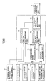
- Fig. 2 is a functional block diagram of a vehicle surroundings monitoring apparatus according to the present invention;
- Fig. 3 is a schematic illustration of fusion solid objects; and
- Fig. 4 is a flowchart showing a routine for recognizing a preceding vehicle.
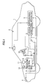
- Referring now to Fig. 1,
reference numeral 1 denotes a vehicle (own vehicle) on which an intervehicle distance automatically adjusting system (Adaptive Cruise Control: ACC) 2 is mounted. TheACC system 2 is constituted by a stereoscopic camera (imaging means) 3, a millimeter wave transmitting and receiving section (radar means) 4, a vehiclesurroundings monitoring apparatus 5 and atraveling control unit 6. When the ACC system is set to a constant speed control mode, the vehicle travels at a speed established by a vehicle driver and when the system is set to a follow-up traveling control mode, the vehicle travels at a speed targeted to the speed of a preceding vehicle with a constant intervehicle distance to the preceding vehicle maintained. - The
stereoscopic camera 3 is composed of a pair (left and right) of CCD cameras using a solid-state image component such as Charge Coupled Device and the left and right cameras are transversely mounted on a front ceiling of a passenger compartment at a specified interval of distance, respectively. The respective cameras take picture images of an exterior object from different view points and input image information to the vehiclesurroundings monitoring apparatus 5. - The millimeter wave transmitting and receiving
section 4 provided at the front end of theown vehicle 1 transmits millimeter wave (for example radio wave having frequency 30G Hz to 100G Hz) forwardly therefrom and receives reflected millimeter wave, inputting sending and receiving data to the vehiclesurroundings monitoring apparatus 5. - Further, there is provided a
vehicle speed sensor 7 in theown vehicle 1 and the detected vehicle speed is inputted to the vehiclesurroundings monitoring apparatus 5 and thetraveling control unit 6. Further, there are provided a steering wheelrotation angle sensor 8 for detecting steering wheel rotation angles and ayaw rate sensor 9 for detecting yaw rates. Signals indicating steering wheel rotation angles and yaw rates are inputted to the vehiclesurroundings monitoring apparatus 5. - The vehicle
surroundings monitoring apparatus 5 comprises a stereoscopic image processing section 15 (first solid object detecting means), a distance measuring section 16 (second solid object detecting means), a fusion solid object establishing section 17 (fusion solid object establishing means), an own travelingregion estimating section 18 and a preceding vehicle recognizing section 19 (first and second reliability judging means and preceding vehicle selecting means). In this embodiment, those sections work in a coordinate system fixed to theown vehicle 1 of the three-dimensional real space. That is, the coordinate system is composed of X coordinate extending in a widthwise direction of theown vehicle 1, Y coordinate extending in a vertical direction of theown vehicle 1, Z coordinate extending in a lengthwise direction of theown vehicle 1 and an origin of the coordinate placed on the road surface directly underneath the central point of two CCD cameras forming thestereoscopic camera 3. The positive sides of X, Y and Z coordinates are established in a right direction, in an upward direction and in a forward direction, respectively. - The stereoscopic
image processing section 15 performs various recognitions of lane markers, side walls, solid objects and the like as follows. First, with respect to a pair of stereoscopic images taken by thestereoscopic CCD camera 4, the stereoscopicimage processing section 15 obtains distance information over the entire image from the deviation amount between corresponding positions according to the principle of trianguration and forms a distance image representing three-dimensional distance distribution based on the distance information. Then, based on the distance image, the stereoscopicimage processing section 15 extracts lane markers, guardrails, curbs, side walls and solid objects like vehicles by performing the known grouping process, the comparison of the distance image with three-dimensional road profile data, side wall data such as guardrails, curbs and side walls along a road and solid object data such as vehicles and other data which are stored in the memory. Thus extracted lane marker data, side wall data and solid object data are denoted by different numbers for each kind of data, respectively. Further, the solid object data are classified into three kinds of objects, a backward moving object moving toward theown vehicle 1, a still object in standstill and a forward moving object moving in the same direction as theown vehicle 1 based on the relationship between the relative variation of the distance from the own vehicle and the vehicle speed of theown vehicle 1. - When an oncoming vehicle or a preceding vehicle is imaged, generally, its front surface, rear surface, corner part and side surface of a vehicle body are projected on picture images. The stereoscopic
image processing section 15 usually extracts the front or rear surface as a solid object and extracts the side surface as a side wall connected through the corner part with the solid object. Accordingly, in case where the extracted solid obj ect is a vehicle, mostly, a side wall connected through a corner part with the solid object is recognized. In case where smear or flare are recognized as a solid object by accident, there is a very small chance that a side wall comes adjacent to the solid object. Accordingly, there is a high possibility that the solid obj ect having two or more surfaces is a vehicle. In the stereoscopicimage processing section 3, if the solid object is connected to the side wall through the corner part, the object is registered specially as a corner-like solid object. - The
distance measuring section 16 performs solidity recognition by processing transmitting and receiving data inputted from the millimeter wave transmitting and receivingsection 4 as follows. That is, thedistance measuring section 16 measures the distance from theown vehicle 1 to the target based on a time between the transmission of a radio wave and the reception of the reflected radio wave. Then, preparing a distribution diagram of distance values, if there is a portion continuously having an identical distance value in the distribution diagram, the portion is extracted and registered as a solid object. - The
distance measuring section 16 stores the data of the solid object extracted and registered in the previous cycle (this solid object will be referred to as "millimeter wave solid object" hereinafter). When thedistance measuring section 16 extracts a new solid obj ect in the present cycle (this solid object will be referred to as "detected millimeter wave solid object" hereinafter), the coincidence is judged between the detected millimeter wave solid obj ect and the millimeter wave solid object. That is, in thedistance measuring section 16, a coincidence probability P is calculated between the detected millimeter wave solid object and the millimeter wave solid object. If the coincidence probability P exceeds a threshold value, it is judged that the detected millimeter wave solid obj ect is identical to the millimeter wave solid object. In this embodiment, the coincidence probability P is obtained according to the following formulas:


- In the
distance measuring section 16, these calculations are performed with respect to all combinations of the detected millimeter wave solid obj ect and the millimeter wave solid obj ect and the combination whose coincidence probability P exceeds the threshold value (for example 30 %) and is largest, is selected. Further, when it is judged that the detected millimeter wave solid object (present one) is identical to the millimeter wave solid object (previous one) , the detected millimeter wave solid object is updated and successively registered as the millimeter wave solid object (previous one). If it is judged that the detected millimeter wave solid object is not identical to the millimeter wave solid object, the detected millimeter wave solid object is registered as a new millimeter wave solid object and the data of the previous one is erased under specified conditions. - The fusion solid
object establishing section 17 inputs information related to respective solid objects (hereinafter, referred to as "image solid object") from the stereoscopicimage processing section 15 and also inputs information related to respective millimeter wave solid objects from thedistance measuring section 16. Fusion solid objects are established by fusing these inputted information. - Specifically, first, the fusion solid
object establishing section 17 judges the coincidence between the respective image solid obj ects and the respective millimeter wave solid objects. That is, in the fusion solidobject establishing section 17, the coincidence probability P is calculated for respective combinations of both solid objects according to the aforesaid formulas (1) to (4) using Z coordinate, X coordinate and the velocity in the Z direction of the respective image solid objects and Z coordinate, X coordinate and the velocity in the Z direction of the respective millimeter wave solid objects. When the image solid object is identical to the millimeter wave solid object, the combination whose coincidence probability P is largest and exceeds a specified value, is determined. - Then, the fusion solid
object establishing section 17 forms respective fusion solid objects by fusing the image solid objects and the millimeter wave solid objects. Referring to Fig. 3, fusion solid objects composed of simple image solid objects are illustrated in rectangular shape, fusion solid objects composed of simple millimeter wave solid objects are illustrated in circular shape, and fusion solid objects composed of the combination of the image solid objects and the millimeter wave solid objects are illustrated in rectangular and circular shape. The respective fusion solid objects include information such as the distance between the fusion solid object and theown vehicle 1, X coordinate, velocity, width and the like of the fusion solid obj ect, and information of the state of movement of forward moving obj ects, still obj ects or oncoming vehicles. In case of the fusion solid object composed of the combination of the image solid object and the millimeter wave solid object, information of the millimeter wave solid object is introduced with top priority in establishing the distance between theown vehicle 1 and the solid object, information of the image solid object is introduced with top priority in establishing X coordinate, information of the millimeter wave solid object is introduced with top priority in establishing velocity, and information of the image solid object is introduced with top priority in establishing the width. - Then, after the new fusion solid objects are established, the fusion solid
object establishing section 17 makes a coincidence judgment between the newly established fusion solid obj ect and the fusion solid object previously registered. In case of the fusion solid object having coincidence, the fusion solid object is continued to be registered and in case of the fusion solid object having no coincidence, the new fusion solid object is registered and the previous fusion solid object is erased. - The own traveling
region estimating section 18 inputs signals indicative of vehicle speeds from thevehicle speed sensor 7, signals indicative of steering wheel rotation angles from the steering wheelrotation angle sensor 8 and signals indicative of yaw rates from theyaw rate sensor 9, respectively and at the same time inputs lane marker data, side wall data and the like from the stereoscopicimage processing section 15, estimating own traveling regions from the own traveling path and the width of lane. - In the own traveling
region estimating section 18, the traveling path of the own vehicle is estimated according to the following four methods: - In case where both or either of left and right lane markers data are obtained and the profile of the lane on which the
own vehicle 1 travels can be estimated from these lane markers data, the traveling path of the own vehicle is formed in parallel with the lane markers in consideration of the width of theown vehicle 1 and the position of theown vehicle 1 in the present lane. - In case where both or either of left and right side walls data are obtained and the profile of the lane on which the
own vehicle 1 travels can be estimated from these side walls data, the traveling path of the own vehicle is formed in parallel with the side walls in consideration of the width of theown vehicle 1 and the position of theown vehicle 1 in the present lane. Method C: Estimation of traveling path based on a trace of the preceding vehicle - The traveling path of the
own vehicle 1 is estimated based on the past traveling trace of the preceding vehicle. - The path of the
own vehicle 1 is estimated based on the traveling conditions such as yaw rate γ, vehicle speed V and steering wheel angle θH of theown vehicle 1 according to the following steps: - First, it is judged whether or not the
yaw rate sensor 9 is effective. If it is effective, the present turning curvature Cua is calculated according to the following formula (5).
- On the other hand, if the
yaw rate sensor 9 is inef fective , it is judged whether or not the vehicle is steered at a steering angle δ more than a prescribed angle (for example 0.57 radian) obtained from the steeringwheel angle θH. In case where the vehicle is steered at a steering angle more than 0.57 radian, the present turning curvature Cua is calculated according to the following formulas (2) , (3) using the steering angle δ and the vehicle speed V of the own vehicle 1:

- Further, if the steering angle is smaller than o.57 radian, the present turning curvature is set to 0 (in a straightforward traveling condition).
- Then, an average turning curvature is calculated from the sum of thus obtained present turning curvature Cua and a turning curvature for a past prescribed time (for example, 0.3 seconds) and the traveling path of the own vehicle is estimated.
- Even in case where the
yaw rate sensor 9 is effective and the turning curvature Cua is calculated according to the formula (5), if the steering angle δ is smaller than 0.57 radian, the present turning curvature Cua may be corrected to 0 (straightforward traveling condition). - Thus, after the traveling path of the own vehicle is estimated, the own traveling
region 18 calculates the width of the lane on which theown vehicle 1 travels. - Specifically, in the own traveling
region estimating section 18, in case where the own traveling path is estimated according to the method A and the stereoscopicimage processing section 15 recognizes both of the left and right lane markers, the space of left and right lane markers is established to be the present lane width. On the other hand, in case where the own traveling path is estimated according to the method A and the stereoscopicimage processing section 15 recognizes either of the left and right lane markers, an average lane width is established to be the present lane width. Further, in case where the own traveling path is estimated according to either of the methods B, C or D, the lane width 2.2 meters which are established in consideration of modern road situations and the like, is established to be the present lane width. Further, in the own travelingregion estimating section 18, after the establishment of the present lane width is completed, the average lane width is calculated from the lane widths accumulated for the past 10 seconds within the range between 3.5 meters and 2.2 meters. Thus, the traveling region of theown vehicle 1 is estimated. - The preceding
vehicle recognizing section 19 investigates the reliability as the millimeter wave fusion solid object and the reliability as the image fusion solid object for the respective fusion solid objects moving forward and the intrusion of these respective fusion solid objects into the own traveling region. In case where at least either of these reliabilities has a specified reliability or more and there are fusionsolid objectsintrudingsuccessivelyinto the own traveling region formore than specif ied time, a forwardmoving obj ect nearest to theown vehicle 1 is selected as a preceding vehicle from these fusion solid objects. - The routine for recognizing the preceding vehicle will be described according to the flowchart shown in Fig. 4 . The routine is executed every specified time. First, at a step S101, a solid object is selected from the respective fusion solid object established in the fusion solid
object establishing section 17. In this embodiment, the fusion solid objects are selected in the order of their proximity from theown vehicle 1. - The program goes to a step S102 where the preceding
vehicle recognizing section 19 investigates whether or not the fusion solid object presently selected is a forward moving solid obj ect which moves in the same forward direction as theown vehicle 1. If it is judged that the fusion solid object presently selected is a forward moving object, the program goes to a step S103 and if it is judged that the fusion solid object is not a forward moving object, the program goes to a step S107. - In case where the program goes from the step S102 to the step S103, the preceding
vehicle recognizing section 19 investigates whether or not the present fusion solid object is a millimeter wave-related fusion solid object, that is, either a single millimeter wave fusion solid object and/or a combination of the millimeter wave fusion solid object and the image fusion solid object. In case where the present fusion solid object is the millimeter wave- related fusion solid object, the program goes to a step S104 in which a millimeter wave registration counter Cm is incremented by one (Cm ← Cm + 1) and then goes to a step S105. On the other hand, in case where it is judged at the step S103 that the present fusion solid object is not a millimeter wave-related fusion solid obj ect, the program goes to a step S105. - The program going from the step S103 or the step S104 to the step S105, the preceding
vehicle recognizing section 19 investigates whether or not the present fusion solid object is a corner-related fusion solid object, that is, either a single image fusion solid object or a combination of the millimeter wave fusion solid object and the image fusion solid object and the image solid object constituting the fusion solid object is registered as a corner- like solid object. If it is judged that the present fusion solid object is a corner-related fusion solid object, the program goes to a step S106 where a corner-like registration counter is incremented by one (Cc ← Cc + 1) and goes to a step S107. On the other hand, if it is judged that the present fusion solid object is not a corner-related fusion solid object, the program goes to a step S107. - When the program goes from the steps S102, S105 or S106 to the step S107, the preceding
vehicle recognizing section 19 checks whether or not all fusion solid objects are selected. If it is judged that all of the fusion solid objects have not yet selected, the program returns to the step S101 and if it is judged that all of the fusion solid objects have selected, the program goes to S108. - At the step S108, the preceding
vehicle recognizing section 19 selects a specified forward moving object from respective fusion solid objects that are judged to be the forward moving objects at the step S102. The selection of the specified forward moving obj ect is performed in the order of their proximity from theown vehicle 1. - Then, the program goes to a step S109 where it is checked whether or not the presently selected forward moving object intrudes into the own traveling region. If it is judged that the presently selected forward moving object intrudes into the own traveling region, the program goes to a step S110 where an intrusion counter Ci for counting the number of intrusion into the own traveling region is incremented by one (Ci ← Ci + 1) and then the program goes to a step S112. On the other hand, if it is judged that the presently selected forward moving obj ect does not intrude into the own traveling region, the program goes to a step S111 where the intrusion counter Ci is cleared (Ci ← 0) and the program goes to a step S115.
- When the program goes from the 110 to the step S112, the preceding
vehicle recognizing section 19 investigates whether or not the intrusion counter Ci for the forward moving object Is larger than a preestablished threshold value Ci1. That is, it is investigated whether or not the present forward moving obj ect intrudes into the own traveling region successively for more than a specified time. If it is judged at the step S112 that the intrusion counter Ci is larger than the threshold value Ci1, the program goes to a step S113 and if it is judged that the intrusion counter Ci is smaller than the threshold value Ci1, the program goes to a step S115. - When the program goes from the step S112 to a step S113, the preceding
vehicle recognizing section 19 investigates whether or not the present forward moving object has a higher degree of the reliability with respect to the actual existence than a preestablished degree of reliability by checking whether or not the millimeter wave registration counter Cm is larger than a preestablished threshold value Cm1. That is, the precedingvehicle recognizing section 19 investigates whether or not the forward moving object has a higher degree of the reliability with respect to the actual existence than a preestablished degree of reliability by investigating whether or not the present forward moving obj ect coincides with the millimeter wave fusion solid obj ect with higher frequency than specified. Then, in case where the millimeter wave counter Cm is larger than the threshold value Cm1, the program goes to a step S116 and in case where the millimeter wave counter Cm is smaller than the threshold value Cm1, the program goes to a step S115. - When the program goes from a step S113 to a step S114, the preceding
vehicle recognizing section 19 investigates whether or not the forward moving object has a higher degree of the reliability with respect to the actual existence than a preestablished degree of reliability by investigating whether or not the corner-like registration counter Cc for the present forward moving object is larger than a preestablished threshold value Cc1. That is, the precedingvehicle recognizing section 19 investigates whether or not the forward moving object has a higher degree of the reliability with respect to the actual existence than a preestablished degree of reliability based on the image solid object by investigating whether or not the present forward moving object coincides with the corner-like solid object with a larger frequency than specified. Further, at the step S114, in case where the corner-like registration counter Cc is larger than the threshold value Cc1, the program goes to a step S116 and in case where the corner-like registration counter Cc is smaller than the threshold value Cc1, the program goes to the step S115. - Then, when the program goes from the steps S113 or S114 to the step S116, the preceding
vehicle recognizing section 19 registers the present forward moving obj ect as a preceding vehicle , the program leaving the routine. - On the other hand, in case where the program goes from the steps S111, S112 or S113 to the step S115, the preceding
vehicle recognizing section 19 investigates whether or not all forward moving objects have been selected. If it is judged that all of the forward moving obj ects have not yet been selected, the program returns to the step S108 and if it is judged that all of the forward moving objects have been selected, the program leaves the routine without performing the registration of the preceding vehicle. - The traveling
control unit 6 has a function of the constant speed traveling control for maintaining the vehicle speed at a speed established by the manual input of a vehicle driver and also has a function of the follow-up traveling control for maintaining the intervehicle distance between the own vehicle and the preceding vehicle at a constant distance. Further, thecontrol unit 6 is connected with a constantspeed traveling switch 10 , the vehiclesurroundings monitoring apparatus 5 and thevehicle speed sensor 7. Further, the constantspeed traveling switch 10 includes a plurality of switches connected to an operating lever provided at the side face of a steering column tube. - The constant
speed traveling switch 10 is constituted by a coast switch for changing the target vehicle speed in a descending direction, a resume switch for changing the target vehicle speed in an ascending direction and the like. Further, there is provided a main switch (not shown) for turning the traveling control on or off in the vicinity of the operating lever. - When the driver turns the main switch on and establishes the operating lever to a desired speed, a signal is inputted from the constant
speed traveling switch 10 to the travelingcontrol unit 6. The travelingcontrol unit 6 drives athrottle actuator 11 based on the signal so as to control the opening angle of athrottle valve 12. As a result, the own vehicle travels automatically at a constant speed. - Further, when the vehicle
surroundings monitoring apparatus 5 judges that the preceding vehicle travels at a lower speed than that established in the travelingcontrol unit 6 of theown vehicle 1, the travelingcontrol unit 6 automatically changes over the control mode from the constant speed traveling control to the follow-up traveling control in which theown vehicle 1 travels with a constant intervehicle distance held. - When the traveling control transfers to the follow-up control, the traveling
control unit 6 establishes an appropriate target intervehicle distance between theown vehicle 1 and the preceding vehicle on the basis of the intervehicle distance obtained by the vehiclesurroundings monitoring apparatus 5, a calculated vehicle speed of the preceding vehicle, and a vehicle speed detected by thevehicle speed sensor 7. The travelingcontrol unit 6 outputs a drive signal to thethrottle actuator 11 and adjusts the opening angle of thethrottle valve 12 such that the intervehicle distance between theown vehicle 1 and the preceding vehicle agrees with the target intervehicle distance. - According to the embodiment of the present invention, the vehicle
surroundings monitoring apparatus 5 establishes fusion solidobjectscomposedof single image fusionsolidobjects, single millimeter wave fusion solid objects, or combinations of the image fusion solid object and the millimeter wave fusion solid object. Further, the vehiclesurroundings monitoring apparatus 5 investigates the reliability of respective fusion solid obj ects coinciding with the image solid object and the reliability of respective fusion solid objects coinciding with the millimeter wave solid object. Then, if either of these reliabilities exceeds a reliability respectively established, the fusion solid object is selected as a preceding vehicle. Thus, since both image means and radar means are used concurrently, more accurate surroundings monitoring can be performed. - Further, since the reliability of the respective fusion solid objects is performed based on the number of registrations as a corner-like solid object or based on the number of detection as a millimeter wave solid object, the preceding vehicle can be selected with high accuracy.
- The entire contents of Japanese Patent Application No. Tokugan 2002-278129 filed September 24, 2002, is incorporated herein by reference.
- While the present invention has been disclosed in terms of the preferred embodiment in order to facilitate better understanding of the invention, it should be appreciated that the invention can be embodied in various ways without departing from the principle of the invention. Therefore, the invention should be understood to include all possible embodiments which can be embodied without departing from the principle of the invention,
Claims (5)
- A vehicle surroundings monitoring apparatus for monitoring surroundings of an own vehicle, characterized by comprising:imaging means for taking picture images and for outputting image information;radar means;first solid object detecting means for detecting first solid objects based on said image information;second solid object detecting means for detecting second solid objects based on signals from said radar means;fusion solid object establishing means for establishing fusion solid objects by fusing said first solid objects and said second solid objects;reliability judging means for judging whether or not said fusion solid objects have a specified level of reliability; andpreceding vehicle selecting means for selecting a preceding vehicle from said fusion solid objects having said specified level of reliability.
- A vehicle surroundings monitoring apparatus for monitoring surroundings of an own vehicle, characterized by comprising:imaging means for taking picture images and for outputting image information;radar means;first solid object detecting means for detecting first solid objects based on said image information;second solid object detecting means for detecting second solid objects based on signals from said radar means;fusion solid object establishing means for establishing fusion solid objects composed of single first solid objects, single second solid objects and a combination of said first solid objects and said second solid objects by fusing said first solid objects and said second solid objects;first reliability judging means for judging a degree of reliability of said fusion solid objects based on a detecting situation of said respective fusion solid objects by said first solid object detecting means;second reliability judging means for judging a degree of reliability of said fusion solid objects based on a detecting situation of said respective fusion solid objects by said second solid object detecting means; andpreceding vehicle selecting means for selecting a preceding vehicle from said fusion solid objects when it is judged that said fusion solid objects have a specified level of reliability according to either of said first reliability judging means and said second reliability judging means.
- The vehicle surroundings monitoring apparatus according to claim 2, characterized in that said first solid object detecting means register a solid object having at least two surfaces connected with each other through a corner as a corner-like solid object and said first reliability judging means judge said reliability of said respective fusion solid objects based on the number of times of coincidence of the fusion solid objects with either of said single first solid objects and a combination of said first solid objects and said second solid objects and at the same time based on the number of times of registration of said respective fusion solid objects as said corner-like solid object by said first solid object detecting means.
- The vehicle surroundings monitoring apparatus according to claim 2, characterized in that said second reliability judging means judge said reliability of said respective fusion solid objects based on the number of times of coincidence of said fusion solid objects with either of said single second solid objects and a combination of said first solid objects and said second solid objects.
- A traveling control system for controlling a traveling of an own vehicle based on information of a preceding vehicle selected by said vehicle surroundings monitoring apparatus described in claims 1, 2, 3 and 4.
Applications Claiming Priority (2)
| Application Number | Priority Date | Filing Date | Title |
|---|---|---|---|
| JP2002278129 | 2002-09-24 | ||
| JP2002278129A JP2004117071A (en) | 2002-09-24 | 2002-09-24 | Vehicle surroundings monitoring apparatus and traveling control system incorporating the same |
Publications (2)
| Publication Number | Publication Date |
|---|---|
| EP1403660A1 true EP1403660A1 (en) | 2004-03-31 |
| EP1403660B1 EP1403660B1 (en) | 2008-12-17 |
Family
ID=31973258
Family Applications (1)
| Application Number | Title | Priority Date | Filing Date |
|---|---|---|---|
| EP03021469A Expired - Fee Related EP1403660B1 (en) | 2002-09-24 | 2003-09-23 | Vehicle surroundings monitoring apparatus and traveling control system incorporating the apparatus |
Country Status (4)
| Country | Link |
|---|---|
| US (1) | US7030775B2 (en) |
| EP (1) | EP1403660B1 (en) |
| JP (1) | JP2004117071A (en) |
| DE (1) | DE60325312D1 (en) |
Cited By (5)
| Publication number | Priority date | Publication date | Assignee | Title |
|---|---|---|---|---|
| WO2009103692A1 (en) | 2008-02-20 | 2009-08-27 | Continental Teves Ag & Co. Ohg | Method and assistance system for detecting objects in the surrounding area of a vehicle |
| WO2010017791A1 (en) * | 2008-08-12 | 2010-02-18 | Continental Automotive Gmbh | Method for detecting expansive static object |
| CN102066970A (en) * | 2008-07-02 | 2011-05-18 | Adc汽车远程控制系统有限公司 | Radar sensor with frontal and lateral emission |
| CN107953828A (en) * | 2016-10-14 | 2018-04-24 | 株式会社万都 | The pedestrian recognition method of vehicle and pedestrian's identifying system of vehicle |
| WO2019127227A1 (en) * | 2017-12-28 | 2019-07-04 | Intel Corporation | Vehicle sensor fusion |
Families Citing this family (119)
| Publication number | Priority date | Publication date | Assignee | Title |
|---|---|---|---|---|
| US5910854A (en) | 1993-02-26 | 1999-06-08 | Donnelly Corporation | Electrochromic polymeric solid films, manufacturing electrochromic devices using such solid films, and processes for making such solid films and devices |
| US6822563B2 (en) | 1997-09-22 | 2004-11-23 | Donnelly Corporation | Vehicle imaging system with accessory control |
| US5877897A (en) | 1993-02-26 | 1999-03-02 | Donnelly Corporation | Automatic rearview mirror, vehicle lighting control and vehicle interior monitoring system using a photosensor array |
| US5668663A (en) | 1994-05-05 | 1997-09-16 | Donnelly Corporation | Electrochromic mirrors and devices |
| US6891563B2 (en) | 1996-05-22 | 2005-05-10 | Donnelly Corporation | Vehicular vision system |
| US7655894B2 (en) | 1996-03-25 | 2010-02-02 | Donnelly Corporation | Vehicular image sensing system |
| US6124886A (en) | 1997-08-25 | 2000-09-26 | Donnelly Corporation | Modular rearview mirror assembly |
| US6326613B1 (en) | 1998-01-07 | 2001-12-04 | Donnelly Corporation | Vehicle interior mirror assembly adapted for containing a rain sensor |
| US8294975B2 (en) | 1997-08-25 | 2012-10-23 | Donnelly Corporation | Automotive rearview mirror assembly |
| US6172613B1 (en) | 1998-02-18 | 2001-01-09 | Donnelly Corporation | Rearview mirror assembly incorporating vehicle information display |
| US8288711B2 (en) | 1998-01-07 | 2012-10-16 | Donnelly Corporation | Interior rearview mirror system with forwardly-viewing camera and a control |
| US6445287B1 (en) | 2000-02-28 | 2002-09-03 | Donnelly Corporation | Tire inflation assistance monitoring system |
| US6329925B1 (en) | 1999-11-24 | 2001-12-11 | Donnelly Corporation | Rearview mirror assembly with added feature modular display |
| US6693517B2 (en) | 2000-04-21 | 2004-02-17 | Donnelly Corporation | Vehicle mirror assembly communicating wirelessly with vehicle accessories and occupants |
| US6477464B2 (en) | 2000-03-09 | 2002-11-05 | Donnelly Corporation | Complete mirror-based global-positioning system (GPS) navigation solution |
| US7370983B2 (en) | 2000-03-02 | 2008-05-13 | Donnelly Corporation | Interior mirror assembly with display |
| WO2007053710A2 (en) | 2005-11-01 | 2007-05-10 | Donnelly Corporation | Interior rearview mirror with display |
| US7167796B2 (en) | 2000-03-09 | 2007-01-23 | Donnelly Corporation | Vehicle navigation system for use with a telematics system |
| AU2001243285A1 (en) | 2000-03-02 | 2001-09-12 | Donnelly Corporation | Video mirror systems incorporating an accessory module |
| US7255451B2 (en) | 2002-09-20 | 2007-08-14 | Donnelly Corporation | Electro-optic mirror cell |
| US7581859B2 (en) | 2005-09-14 | 2009-09-01 | Donnelly Corp. | Display device for exterior rearview mirror |
| ES2287266T3 (en) | 2001-01-23 | 2007-12-16 | Donnelly Corporation | IMPROVED VEHICLE LIGHTING SYSTEM. |
| EP1504276B1 (en) | 2002-05-03 | 2012-08-08 | Donnelly Corporation | Object detection system for vehicle |
| US6918674B2 (en) | 2002-05-03 | 2005-07-19 | Donnelly Corporation | Vehicle rearview mirror system |
| US7329013B2 (en) | 2002-06-06 | 2008-02-12 | Donnelly Corporation | Interior rearview mirror system with compass |
| WO2003105099A1 (en) | 2002-06-06 | 2003-12-18 | Donnelly Corporation | Interior rearview mirror system with compass |
| US7310177B2 (en) | 2002-09-20 | 2007-12-18 | Donnelly Corporation | Electro-optic reflective element assembly |
| WO2004103772A2 (en) | 2003-05-19 | 2004-12-02 | Donnelly Corporation | Mirror assembly for vehicle |
| AU2003278863A1 (en) | 2002-09-20 | 2004-04-08 | Donnelly Corporation | Mirror reflective element assembly |
| NL1023016C2 (en) * | 2003-03-25 | 2004-09-30 | Tno | Detection system, method for detecting objects and computer program therefor. |
| JP4265931B2 (en) * | 2003-05-22 | 2009-05-20 | 富士重工業株式会社 | Leading vehicle detection device |
| JP3918791B2 (en) | 2003-09-11 | 2007-05-23 | トヨタ自動車株式会社 | Object detection device |
| JP3941765B2 (en) * | 2003-09-11 | 2007-07-04 | トヨタ自動車株式会社 | Object detection device |
| US7446924B2 (en) | 2003-10-02 | 2008-11-04 | Donnelly Corporation | Mirror reflective element assembly including electronic component |
| US7308341B2 (en) | 2003-10-14 | 2007-12-11 | Donnelly Corporation | Vehicle communication system |
| US7542592B2 (en) * | 2004-03-29 | 2009-06-02 | Siemesn Corporate Research, Inc. | Systems and methods for face detection and recognition using infrared imaging |
| US7526103B2 (en) | 2004-04-15 | 2009-04-28 | Donnelly Corporation | Imaging system for vehicle |
| JP2006047057A (en) * | 2004-08-03 | 2006-02-16 | Fuji Heavy Ind Ltd | Outside-vehicle monitoring device, and traveling control device provided with this outside-vehicle monitoring device |
| DE102004038494A1 (en) | 2004-08-07 | 2006-03-16 | Robert Bosch Gmbh | Method and device for operating a sensor system |
| JP2006090957A (en) * | 2004-09-27 | 2006-04-06 | Nissan Motor Co Ltd | Surrounding object detecting device for moving body, and surrounding object detection method for moving body |
| US7881496B2 (en) | 2004-09-30 | 2011-02-01 | Donnelly Corporation | Vision system for vehicle |
| US20060091654A1 (en) * | 2004-11-04 | 2006-05-04 | Autoliv Asp, Inc. | Sensor system with radar sensor and vision sensor |
| US20060091653A1 (en) * | 2004-11-04 | 2006-05-04 | Autoliv Asp, Inc. | System for sensing impending collision and adjusting deployment of safety device |
| JP4530827B2 (en) * | 2004-12-08 | 2010-08-25 | ダイハツ工業株式会社 | Image processing method and image processing apparatus |
| JP4426436B2 (en) * | 2004-12-27 | 2010-03-03 | 株式会社日立製作所 | Vehicle detection device |
| JP4451315B2 (en) * | 2005-01-06 | 2010-04-14 | 富士重工業株式会社 | Vehicle driving support device |
| EP1883855B1 (en) | 2005-05-16 | 2011-07-20 | Donnelly Corporation | Vehicle mirror assembly with indicia at reflective element |
| JP4626400B2 (en) * | 2005-05-25 | 2011-02-09 | 日産自動車株式会社 | Overhead image display device and overhead image display method |
| JP4980606B2 (en) * | 2005-11-15 | 2012-07-18 | 株式会社岩根研究所 | Mobile automatic monitoring device |
| JP4712562B2 (en) * | 2006-01-13 | 2011-06-29 | 富士重工業株式会社 | Vehicle front three-dimensional object recognition device |
| US8676492B2 (en) * | 2006-01-19 | 2014-03-18 | GM Global Technology Operations LLC | Map-aided vision-based lane sensing |
| US8194132B2 (en) | 2006-01-20 | 2012-06-05 | Old World Industries, Llc | System for monitoring an area adjacent a vehicle |
| JP4595833B2 (en) * | 2006-02-24 | 2010-12-08 | トヨタ自動車株式会社 | Object detection device |
| MX2008011219A (en) | 2006-03-09 | 2008-09-11 | Gentex Corp | Vehicle rearview assembly including a high intensity display. |
| JP4753765B2 (en) * | 2006-03-30 | 2011-08-24 | ダイハツ工業株式会社 | Obstacle recognition method |
| US7972045B2 (en) | 2006-08-11 | 2011-07-05 | Donnelly Corporation | Automatic headlamp control system |
| JP2008117073A (en) * | 2006-11-01 | 2008-05-22 | Fuji Heavy Ind Ltd | Interruption vehicle detection device |
| JP4254844B2 (en) * | 2006-11-01 | 2009-04-15 | トヨタ自動車株式会社 | Travel control plan evaluation device |
| DE102007018470A1 (en) * | 2007-04-19 | 2008-10-23 | Robert Bosch Gmbh | Driver assistance system and method for object plausibility |
| JP5012270B2 (en) * | 2007-07-10 | 2012-08-29 | トヨタ自動車株式会社 | Object detection device |
| JP4949198B2 (en) * | 2007-10-29 | 2012-06-06 | 三菱ふそうトラック・バス株式会社 | Device for detecting an object to be monitored in a vehicle collision damage reducing device |
| SE532004C2 (en) * | 2008-02-07 | 2009-09-22 | Scania Cv Ab | Methods and devices for adaptive cruise control, computer programs, computer software products, computers and vehicles |
| JP5038192B2 (en) * | 2008-03-05 | 2012-10-03 | 本田技研工業株式会社 | Vehicle safety device |
| US8154418B2 (en) | 2008-03-31 | 2012-04-10 | Magna Mirrors Of America, Inc. | Interior rearview mirror system |
| US8095276B2 (en) * | 2008-10-15 | 2012-01-10 | Autoliv Asp, Inc. | Sensor system including a confirmation sensor for detecting an impending collision |
| US9487144B2 (en) | 2008-10-16 | 2016-11-08 | Magna Mirrors Of America, Inc. | Interior mirror assembly with display |
| US20100225522A1 (en) * | 2009-03-06 | 2010-09-09 | Demersseman Bernard Guy | Sensor system for detecting an impending collision of a vehicle |
| CN102449672B (en) * | 2009-06-02 | 2013-05-01 | 丰田自动车株式会社 | Vehicular peripheral surveillance device |
| JP5505702B2 (en) * | 2010-02-24 | 2014-05-28 | アイシン精機株式会社 | Vehicle periphery monitoring device |
| US9013620B2 (en) | 2011-04-20 | 2015-04-21 | Trw Automotive U.S. Llc | Multiple band imager and method |
| JP5522157B2 (en) * | 2011-12-14 | 2014-06-18 | 株式会社デンソー | Preceding vehicle determination device and inter-vehicle distance control device |
| US10457209B2 (en) | 2012-02-22 | 2019-10-29 | Magna Electronics Inc. | Vehicle vision system with multi-paned view |
| US9319637B2 (en) | 2012-03-27 | 2016-04-19 | Magna Electronics Inc. | Vehicle vision system with lens pollution detection |
| US8879139B2 (en) | 2012-04-24 | 2014-11-04 | Gentex Corporation | Display mirror assembly |
| KR101380888B1 (en) * | 2012-07-24 | 2014-04-02 | 현대모비스 주식회사 | Apparatus and Method for Calculating Vehicle-Distance |
| EP2894619A4 (en) | 2012-09-03 | 2016-03-16 | Toyota Motor Co Ltd | Collision determination device and collision determination method |
| US9707896B2 (en) | 2012-10-15 | 2017-07-18 | Magna Electronics Inc. | Vehicle camera lens dirt protection via air flow |
| JP2014137288A (en) * | 2013-01-17 | 2014-07-28 | Mitsubishi Electric Corp | Device and method for monitoring surroundings of vehicle |
| US9445057B2 (en) | 2013-02-20 | 2016-09-13 | Magna Electronics Inc. | Vehicle vision system with dirt detection |
| US9598018B2 (en) | 2013-03-15 | 2017-03-21 | Gentex Corporation | Display mirror assembly |
| JP5812061B2 (en) | 2013-08-22 | 2015-11-11 | 株式会社デンソー | Target detection apparatus and program |
| US9575315B2 (en) | 2013-09-24 | 2017-02-21 | Gentex Corporation | Display mirror assembly |
| JP5929870B2 (en) * | 2013-10-17 | 2016-06-08 | 株式会社デンソー | Target detection device |
| US9511715B2 (en) | 2014-01-31 | 2016-12-06 | Gentex Corporation | Backlighting assembly for display for reducing cross-hatching |
| JP5991332B2 (en) * | 2014-02-05 | 2016-09-14 | トヨタ自動車株式会社 | Collision avoidance control device |
| EP3119643B1 (en) | 2014-03-21 | 2018-05-23 | Gentex Corporation | Tri-modal display mirror assembly |
| CN106163873B (en) | 2014-04-01 | 2019-04-26 | 金泰克斯公司 | Automatic display mirror assembly |
| US9694751B2 (en) | 2014-09-19 | 2017-07-04 | Gentex Corporation | Rearview assembly |
| US9694752B2 (en) | 2014-11-07 | 2017-07-04 | Gentex Corporation | Full display mirror actuator |
| US10071689B2 (en) | 2014-11-13 | 2018-09-11 | Gentex Corporation | Rearview mirror system with a display |
| KR101997815B1 (en) | 2014-12-03 | 2019-07-08 | 젠텍스 코포레이션 | Display mirror assembly |
| USD746744S1 (en) | 2014-12-05 | 2016-01-05 | Gentex Corporation | Rearview device |
| US9744907B2 (en) | 2014-12-29 | 2017-08-29 | Gentex Corporation | Vehicle vision system having adjustable displayed field of view |
| US9720278B2 (en) | 2015-01-22 | 2017-08-01 | Gentex Corporation | Low cost optical film stack |
| JP6365385B2 (en) * | 2015-04-17 | 2018-08-01 | トヨタ自動車株式会社 | Three-dimensional object detection apparatus and three-dimensional object detection method |
| EP3286038A4 (en) | 2015-04-20 | 2018-04-25 | Gentex Corporation | Rearview assembly with applique |
| CN107614324B (en) | 2015-05-18 | 2020-11-27 | 金泰克斯公司 | Complete display rearview device |
| EP3310618A4 (en) | 2015-06-22 | 2018-07-04 | Gentex Corporation | System and method for processing streamed video images to correct for flicker of amplitude-modulated lights |
| JP6661303B2 (en) * | 2015-08-25 | 2020-03-11 | キヤノン株式会社 | Position detecting device, position detecting method, exposure apparatus and exposure method |
| USD797627S1 (en) | 2015-10-30 | 2017-09-19 | Gentex Corporation | Rearview mirror device |
| WO2017075420A1 (en) | 2015-10-30 | 2017-05-04 | Gentex Corporation | Toggle paddle |
| CN108349436B (en) | 2015-10-30 | 2019-12-20 | 金泰克斯公司 | Rear-view device |
| USD798207S1 (en) | 2015-10-30 | 2017-09-26 | Gentex Corporation | Rearview mirror assembly |
| USD800618S1 (en) | 2015-11-02 | 2017-10-24 | Gentex Corporation | Toggle paddle for a rear view device |
| JP2017156219A (en) * | 2016-03-02 | 2017-09-07 | 沖電気工業株式会社 | Tracking device, tracking method, and program |
| USD845851S1 (en) | 2016-03-31 | 2019-04-16 | Gentex Corporation | Rearview device |
| USD817238S1 (en) | 2016-04-29 | 2018-05-08 | Gentex Corporation | Rearview device |
| JP6223504B1 (en) | 2016-05-18 | 2017-11-01 | 三菱電機株式会社 | Radar device and sensor fusion device using the same |
| US10025138B2 (en) | 2016-06-06 | 2018-07-17 | Gentex Corporation | Illuminating display with light gathering structure |
| DE102016009302A1 (en) * | 2016-08-01 | 2018-02-01 | Lucas Automotive Gmbh | Control system and control method for selecting and tracking a motor vehicle |
| USD809984S1 (en) | 2016-12-07 | 2018-02-13 | Gentex Corporation | Rearview assembly |
| USD854473S1 (en) | 2016-12-16 | 2019-07-23 | Gentex Corporation | Rearview assembly |
| US20180191966A1 (en) | 2016-12-30 | 2018-07-05 | Gentex Corporation | Full display mirror with on-demand spotter view |
| US10735638B2 (en) | 2017-03-17 | 2020-08-04 | Gentex Corporation | Dual display reverse camera system |
| US20180341822A1 (en) * | 2017-05-26 | 2018-11-29 | Dura Operating, Llc | Method and system for classifying objects in a perception scene graph by using a scene-detection-schema |
| JP7211145B2 (en) * | 2019-02-20 | 2023-01-24 | トヨタ自動車株式会社 | vehicle controller |
| CN112101069A (en) | 2019-06-18 | 2020-12-18 | 华为技术有限公司 | Method and device for determining driving area information |
| DE102019135851A1 (en) * | 2019-12-30 | 2021-07-01 | Daimler Ag | Method for suppressing ambiguous measurement data from environmental sensors |
| CN116324506A (en) * | 2020-09-24 | 2023-06-23 | 三菱电机株式会社 | Information processing system, information processing device, program, and information processing method |
Citations (6)
| Publication number | Priority date | Publication date | Assignee | Title |
|---|---|---|---|---|
| JPH06230115A (en) | 1993-02-01 | 1994-08-19 | Toyota Motor Corp | Vehicular gap detector |
| EP0697641A2 (en) * | 1994-07-12 | 1996-02-21 | Honda Giken Kogyo Kabushiki Kaisha | Lane image processing system for vehicle |
| DE19629775A1 (en) * | 1995-11-17 | 1997-05-22 | Mitsubishi Electric Corp | Method and device for monitoring the surroundings of a vehicle and for detecting a failure of the monitoring device |
| EP0890470A2 (en) * | 1997-07-07 | 1999-01-13 | Honda Giken Kogyo Kabushiki Kaisha | Vehicle control system for lane changing |
| EP1065520A2 (en) | 1999-06-28 | 2001-01-03 | Hitachi, Ltd. | Vehicle control method and vehicle warning method |
| US6191704B1 (en) * | 1996-12-19 | 2001-02-20 | Hitachi, Ltd, | Run environment recognizing apparatus |
Family Cites Families (17)
| Publication number | Priority date | Publication date | Assignee | Title |
|---|---|---|---|---|
| JP3230642B2 (en) * | 1995-05-29 | 2001-11-19 | ダイハツ工業株式会社 | Vehicle ahead detection device |
| JPH0980153A (en) * | 1995-09-08 | 1997-03-28 | Mitsubishi Electric Corp | Distance measuring apparatus |
| JP3336825B2 (en) * | 1995-09-25 | 2002-10-21 | 三菱自動車工業株式会社 | Obstacle recognition device |
| JP3349060B2 (en) * | 1997-04-04 | 2002-11-20 | 富士重工業株式会社 | Outside monitoring device |
| US6161071A (en) * | 1999-03-12 | 2000-12-12 | Navigation Technologies Corporation | Method and system for an in-vehicle computing architecture |
| JP4308381B2 (en) * | 1999-09-29 | 2009-08-05 | 富士通テン株式会社 | Perimeter monitoring sensor |
| JP3666332B2 (en) * | 2000-01-07 | 2005-06-29 | 日産自動車株式会社 | Pedestrian detection device |
| US20030102997A1 (en) * | 2000-02-13 | 2003-06-05 | Hexagon System Engineering Ltd. | Vehicle communication network |
| JP4311861B2 (en) * | 2000-05-18 | 2009-08-12 | 富士通テン株式会社 | Vehicle object detection device |
| WO2002021156A2 (en) * | 2000-09-08 | 2002-03-14 | Raytheon Company | Path prediction system and method |
| JP2002099906A (en) * | 2000-09-22 | 2002-04-05 | Mazda Motor Corp | Object-recognizing device |
| JP3626905B2 (en) * | 2000-11-24 | 2005-03-09 | 富士重工業株式会社 | Outside monitoring device |
| GB0111979D0 (en) * | 2001-05-17 | 2001-07-04 | Lucas Industries Ltd | Sensing apparatus for vehicles |
| JP3880841B2 (en) * | 2001-11-15 | 2007-02-14 | 富士重工業株式会社 | Outside monitoring device |
| US6721659B2 (en) * | 2002-02-01 | 2004-04-13 | Ford Global Technologies, Llc | Collision warning and safety countermeasure system |
| US6771208B2 (en) * | 2002-04-24 | 2004-08-03 | Medius, Inc. | Multi-sensor system |
| JP2004037239A (en) * | 2002-07-03 | 2004-02-05 | Fuji Heavy Ind Ltd | Identical object judging method and system, and misregistration correcting method and system |
-
2002
- 2002-09-24 JP JP2002278129A patent/JP2004117071A/en active Pending
-
2003
- 2003-09-18 US US10/664,999 patent/US7030775B2/en not_active Expired - Fee Related
- 2003-09-23 EP EP03021469A patent/EP1403660B1/en not_active Expired - Fee Related
- 2003-09-23 DE DE60325312T patent/DE60325312D1/en not_active Expired - Lifetime
Patent Citations (6)
| Publication number | Priority date | Publication date | Assignee | Title |
|---|---|---|---|---|
| JPH06230115A (en) | 1993-02-01 | 1994-08-19 | Toyota Motor Corp | Vehicular gap detector |
| EP0697641A2 (en) * | 1994-07-12 | 1996-02-21 | Honda Giken Kogyo Kabushiki Kaisha | Lane image processing system for vehicle |
| DE19629775A1 (en) * | 1995-11-17 | 1997-05-22 | Mitsubishi Electric Corp | Method and device for monitoring the surroundings of a vehicle and for detecting a failure of the monitoring device |
| US6191704B1 (en) * | 1996-12-19 | 2001-02-20 | Hitachi, Ltd, | Run environment recognizing apparatus |
| EP0890470A2 (en) * | 1997-07-07 | 1999-01-13 | Honda Giken Kogyo Kabushiki Kaisha | Vehicle control system for lane changing |
| EP1065520A2 (en) | 1999-06-28 | 2001-01-03 | Hitachi, Ltd. | Vehicle control method and vehicle warning method |
Cited By (9)
| Publication number | Priority date | Publication date | Assignee | Title |
|---|---|---|---|---|
| WO2009103692A1 (en) | 2008-02-20 | 2009-08-27 | Continental Teves Ag & Co. Ohg | Method and assistance system for detecting objects in the surrounding area of a vehicle |
| US8457359B2 (en) | 2008-02-20 | 2013-06-04 | Continental Teves Ag & Co. Ohg | Method and assistance system for detecting objects in the surrounding area of a vehicle |
| CN102066970A (en) * | 2008-07-02 | 2011-05-18 | Adc汽车远程控制系统有限公司 | Radar sensor with frontal and lateral emission |
| CN102066970B (en) * | 2008-07-02 | 2015-02-25 | Adc汽车远程控制系统有限公司 | Radar sensor with frontal and lateral emission |
| WO2010017791A1 (en) * | 2008-08-12 | 2010-02-18 | Continental Automotive Gmbh | Method for detecting expansive static object |
| CN102124370A (en) * | 2008-08-12 | 2011-07-13 | 大陆汽车有限公司 | Method for detecting expansive static object |
| CN107953828A (en) * | 2016-10-14 | 2018-04-24 | 株式会社万都 | The pedestrian recognition method of vehicle and pedestrian's identifying system of vehicle |
| WO2019127227A1 (en) * | 2017-12-28 | 2019-07-04 | Intel Corporation | Vehicle sensor fusion |
| US11585920B2 (en) | 2017-12-28 | 2023-02-21 | Intel Corporation | Vehicle sensor fusion |
Also Published As
| Publication number | Publication date |
|---|---|
| DE60325312D1 (en) | 2009-01-29 |
| US20040066285A1 (en) | 2004-04-08 |
| JP2004117071A (en) | 2004-04-15 |
| EP1403660B1 (en) | 2008-12-17 |
| US7030775B2 (en) | 2006-04-18 |
Similar Documents
| Publication | Publication Date | Title |
|---|---|---|
| EP1403660B1 (en) | Vehicle surroundings monitoring apparatus and traveling control system incorporating the apparatus | |
| EP1455323B1 (en) | Vehicle drive assist system | |
| EP1396732B1 (en) | Vehicle surroundings monitoring apparatus and traveling control system incorporating the apparatus | |
| EP1354767B1 (en) | Vehicle surroundings monitoring apparatus and vehicle traveling control system incorporating the apparatus | |
| EP1564703B1 (en) | Vehicle driving assist system | |
| US10019017B2 (en) | Autonomous driving system | |
| EP3048022B1 (en) | Collision avoidance control system and control method | |
| US10106161B2 (en) | Vehicle travel control device | |
| JP3671825B2 (en) | Inter-vehicle distance estimation device | |
| KR100521119B1 (en) | Obstacle detecting apparatus for vehicle | |
| JP2900737B2 (en) | Inter-vehicle distance detection device | |
| US6961661B2 (en) | Vehicle surroundings monitoring apparatus and traveling control system incorporating the apparatus | |
| US6169572B1 (en) | Object recognizing apparatus for vehicle and the method thereof | |
| US7302325B2 (en) | Vehicle drive assist system | |
| JP2017121912A (en) | Traveling control system of vehicle | |
| CN110045736A (en) | A kind of curve barrier preventing collision method and its system based on unmanned plane | |
| EP1017036A1 (en) | Method and apparatus for detecting deviation of automobile from lane | |
| JP3440956B2 (en) | Roadway detection device for vehicles | |
| JP6609292B2 (en) | Outside environment recognition device | |
| CN114523968B (en) | Surrounding vehicle monitoring device and surrounding vehicle monitoring method | |
| US20230001923A1 (en) | Vehicular automatic emergency braking system with cross-path threat determination | |
| US20230294702A1 (en) | Control device, control method, and storage medium | |
| CN116890845A (en) | map generation device |
Legal Events
| Date | Code | Title | Description |
|---|---|---|---|
| PUAI | Public reference made under article 153(3) epc to a published international application that has entered the european phase |
Free format text: ORIGINAL CODE: 0009012 |
|
| 17P | Request for examination filed |
Effective date: 20040121 |
|
| AK | Designated contracting states |
Kind code of ref document: A1 Designated state(s): AT BE BG CH CY CZ DE DK EE ES FI FR GB GR HU IE IT LI LU MC NL PT RO SE SI SK TR |
|
| AX | Request for extension of the european patent |
Extension state: AL LT LV MK |
|
| AKX | Designation fees paid |
Designated state(s): DE FR GB |
|
| 17Q | First examination report despatched |
Effective date: 20070622 |
|
| GRAP | Despatch of communication of intention to grant a patent |
Free format text: ORIGINAL CODE: EPIDOSNIGR1 |
|
| GRAS | Grant fee paid |
Free format text: ORIGINAL CODE: EPIDOSNIGR3 |
|
| GRAA | (expected) grant |
Free format text: ORIGINAL CODE: 0009210 |
|
| AK | Designated contracting states |
Kind code of ref document: B1 Designated state(s): DE FR GB |
|
| REG | Reference to a national code |
Ref country code: GB Ref legal event code: FG4D |
|
| REF | Corresponds to: |
Ref document number: 60325312 Country of ref document: DE Date of ref document: 20090129 Kind code of ref document: P |
|
| PLBE | No opposition filed within time limit |
Free format text: ORIGINAL CODE: 0009261 |
|
| STAA | Information on the status of an ep patent application or granted ep patent |
Free format text: STATUS: NO OPPOSITION FILED WITHIN TIME LIMIT |
|
| 26N | No opposition filed |
Effective date: 20090918 |
|
| GBPC | Gb: european patent ceased through non-payment of renewal fee |
Effective date: 20090923 |
|
| REG | Reference to a national code |
Ref country code: FR Ref legal event code: ST Effective date: 20100531 |
|
| PG25 | Lapsed in a contracting state [announced via postgrant information from national office to epo] |
Ref country code: FR Free format text: LAPSE BECAUSE OF NON-PAYMENT OF DUE FEES Effective date: 20090930 |
|
| PG25 | Lapsed in a contracting state [announced via postgrant information from national office to epo] |
Ref country code: GB Free format text: LAPSE BECAUSE OF NON-PAYMENT OF DUE FEES Effective date: 20090923 |
|
| PGFP | Annual fee paid to national office [announced via postgrant information from national office to epo] |
Ref country code: DE Payment date: 20100915 Year of fee payment: 8 |
|
| PG25 | Lapsed in a contracting state [announced via postgrant information from national office to epo] |
Ref country code: DE Free format text: LAPSE BECAUSE OF NON-PAYMENT OF DUE FEES Effective date: 20130403 |
|
| REG | Reference to a national code |
Ref country code: DE Ref legal event code: R119 Ref document number: 60325312 Country of ref document: DE Effective date: 20130403 |