EP1402863B1 - Thin comfortable sanitary napkin having reduced bunching - Google Patents
Thin comfortable sanitary napkin having reduced bunching Download PDFInfo
- Publication number
- EP1402863B1 EP1402863B1 EP03022174A EP03022174A EP1402863B1 EP 1402863 B1 EP1402863 B1 EP 1402863B1 EP 03022174 A EP03022174 A EP 03022174A EP 03022174 A EP03022174 A EP 03022174A EP 1402863 B1 EP1402863 B1 EP 1402863B1
- Authority
- EP
- European Patent Office
- Prior art keywords
- sanitary napkin
- preferential bending
- layer
- absorbent
- longitudinal side
- Prior art date
- Legal status (The legal status is an assumption and is not a legal conclusion. Google has not performed a legal analysis and makes no representation as to the accuracy of the status listed.)
- Expired - Fee Related
Links
Images
Classifications
-
- A—HUMAN NECESSITIES
- A61—MEDICAL OR VETERINARY SCIENCE; HYGIENE
- A61F—FILTERS IMPLANTABLE INTO BLOOD VESSELS; PROSTHESES; DEVICES PROVIDING PATENCY TO, OR PREVENTING COLLAPSING OF, TUBULAR STRUCTURES OF THE BODY, e.g. STENTS; ORTHOPAEDIC, NURSING OR CONTRACEPTIVE DEVICES; FOMENTATION; TREATMENT OR PROTECTION OF EYES OR EARS; BANDAGES, DRESSINGS OR ABSORBENT PADS; FIRST-AID KITS
- A61F13/00—Bandages or dressings; Absorbent pads
- A61F13/15—Absorbent pads, e.g. sanitary towels, swabs or tampons for external or internal application to the body; Supporting or fastening means therefor; Tampon applicators
- A61F13/45—Absorbent pads, e.g. sanitary towels, swabs or tampons for external or internal application to the body; Supporting or fastening means therefor; Tampon applicators characterised by the shape
- A61F13/47—Sanitary towels, incontinence pads or napkins
- A61F13/4704—Sanitary towels, incontinence pads or napkins having preferential bending zones, e.g. fold lines or grooves
-
- A—HUMAN NECESSITIES
- A61—MEDICAL OR VETERINARY SCIENCE; HYGIENE
- A61F—FILTERS IMPLANTABLE INTO BLOOD VESSELS; PROSTHESES; DEVICES PROVIDING PATENCY TO, OR PREVENTING COLLAPSING OF, TUBULAR STRUCTURES OF THE BODY, e.g. STENTS; ORTHOPAEDIC, NURSING OR CONTRACEPTIVE DEVICES; FOMENTATION; TREATMENT OR PROTECTION OF EYES OR EARS; BANDAGES, DRESSINGS OR ABSORBENT PADS; FIRST-AID KITS
- A61F13/00—Bandages or dressings; Absorbent pads
- A61F13/15—Absorbent pads, e.g. sanitary towels, swabs or tampons for external or internal application to the body; Supporting or fastening means therefor; Tampon applicators
- A61F13/45—Absorbent pads, e.g. sanitary towels, swabs or tampons for external or internal application to the body; Supporting or fastening means therefor; Tampon applicators characterised by the shape
- A61F13/47—Sanitary towels, incontinence pads or napkins
- A61F13/476—Sanitary towels, incontinence pads or napkins characterised by encircling the crotch region of the undergarment
Definitions
- the present invention relates to a sanitary napkin that is thin, absorbent and has a flexibility selected to provide a good comfort potential and at the same time reduce the likelihood of uncontrolled deformation in use.
- sanitary napkins that are highly flexible are known to suffer from high failure rates which can be traced to the inability of the sanitary napkin to maintain firm contact with the user's body. As a consequence, the menstrual liquid discharged cannot be captured immediately into the sanitary napkin and liquid can travel along the user's body and stain the users undergarments or outer garments.
- a sanitary napkin that bunches is compressed in a way to significantly reduce its liquid absorption area and prevent close conformation with the vaginal opening. This may explain the high incidence of failure rates observed in connection with sanitary napkins that are very flexible.
- a sanitary napkin which has an absorbent core intermediate the top sheet and the back sheet and wherein the major surface which is oriented towards the top sheet has one or more lines of weakness therein which comprise discrete sites which are longitudinally concave towards the lateral centerline of the sanitary napkin.
- the sanitary napkin shall be deformed during use to a convex upwardly shaped configuration at the vaginal orifice and the gluteal groove and to a concave upward configuration around the mons pubis of the wearer.
- EP 1 206 926 A2 is about a sanitary napkin which is highly absorbent and yet reasonably flexible, which has a thickness of less than about 5 mm and comprises a central absorbent zone with adjacent first and second regions wherein the stiffness of the second region is less than 90 % of the stiffness of the first region.
- the second region of the central absorbent zone is reported to exhibit one or more mechanical modifications selected from the group consisting of cutting, slitting, perforating or tenderizing.
- the object underlying EP 1 206 926 A2 has been to provide a sanitary napkin having improved flexibility in strategic areas of said napkin.
- US 2001/0007065 A1 a sanitary napkin is described which is provided with densified end channels in opposite end regions which are oriented parallel to the transverse centerline.
- US 2001/0007065 A1 is fostering at disposable absorbent products for use in feminine hygiene which are capable of adapting to and closely fitting the perineal area of the wearer.
- a feminine sanitary napkin 20 has a main body 22 with a first transverse end 26 and an opposite second transverse end 28 defining therebetween a length.
- the main body 22 also has two longitudinal sides, namely a longitudinal side edge 30 and an opposite longitudinal side edge 32 defining therebetween a width.
- the main body 22 has a central longitudinal axis 34 that is an imaginary line bisecting the sanitary napkin 20 in two substantially identical halves.
- the main body 22 also has an imaginary transverse centerline 36 perpendicular to the central longitudinal axis 34.
- the main body 22 is of a laminate construction and preferably comprises a liquid permeable cover layer 42, an absorbent core 44, and a liquid impervious barrier layer 50.
- the absorbent core 44 may comprise a single layer, or alternatively, the absorbent core 44 preferably has two components as shown, including a first absorbent layer 46 and a second absorbent layer 48.
- the first absorbent layer 46 is adapted to rapidly acquire liquid from the cover layer 42 and to hold the liquid until the second absorbent layer 48 can absorb and retain the absorbed liquid.
- the absorbent core 44 comprises a single layer, it is preferably the second absorbent layer 48 as described hereinbelow.
- a preferential bending zone 45 is included in each of the transverse end regions 66, 68 of the sanitary napkin 20.
- the preferential bending zones 45 are located solely in the transverse end regions 66, 68 of the sanitary napkin 20 and there are no preferential bending zones located in the central region of the sanitary napkin.
- the terminology "central region" of the sanitary napkin, as used herein is that region of the sanitary napkin that registers with the vaginal opening of the user when the sanitary napkin is worn.
- the transverse end regions 66, 68 accordingly, are the regions of the sanitary napkin that are intermediate the first and second transverse ends 26, 28 of the napkin 20 and the central region, respectively.
- the transverse end regions 66, 68 of the sanitary napkin 20 are able to independently twist along their respective longitudinal axes while allowing the central region 70 to adapt to the contours of the wearer's body and thereby allow the sanitary napkin conform to the shape of the wearer's body, providing the sanitary napkin with enhanced comfort and stability in use.
- the main body 22 of the sanitary napkin 20 is provided with a preferential bending zone 45 in each transverse end region of the sanitary napkin.
- the preferential bending zone 45 crosses the longitudinal axis of the sanitary napkin. This obliquely extending preferential bending zone 45 extends from one longitudinal side area of the sanitary napkin 20 to the opposite longitudinal side area, crossing the imaginary central longitudinal axis 34 of the sanitary napkin 20.
- the obliqueness requirement of the preferential bending zone 45 is met as long as a substantial segment of the preferential bending zone 45 is oblique with relation to the central longitudinal axis 34. The segment that is oblique crosses the longitudinal axis.
- a preferred method of creating the preferential bending zones is to mechanically emboss the surface of the main body of the sanitary napkin, resulting in a series of local densifications of the absorbent material.
- An advantage afforded by forming the oblique preferential bending zones as embossed channels is that they contribute to a more uniform distribution of bodily fluids along the surface of the sanitary napkin by channeling the fluids away from the point of contact.
- the sanitary napkin is also more efficient in collecting bodily fluids, since a larger surface area is available for contact with the fluids than when bunching occurs.
- the preferential bending zone 45 can be straight, arcuate, form a repeating pattern, such as a wavy pattern or a zigzag pattern or a combination of these shapes.
- a repeating pattern is present in a segment of the preferential bending zone 45, the obliqueness of that segment is determined by considering an imaginary line that is contained within the repeating pattern and that either forms or at least approximates a line of symmetry for the pattern.
- the transverse ends of the sanitary napkin may be provided with a plurality of preferential bending zones in a variety of patterns, including a plurality of substantially parallel lines, a plurality of parallel and converging lines, etc.
- the spacing between the parallel lines is about 2 cm.
- the sanitary napkin 20 has a plurality of preferential bending zones that converge towards a common point of intersection to create the appearance of a "basket weave" type pattern extending over a major portion of the longitudinal dimension of the transverse end regions of the main body of the sanitary napkin.
- the sanitary napkin has a plurality of obliquely extending preferential bending zones 45 that are disposed across the surface of the transverse end regions 66, 68 of the main body 22 of the sanitary napkin 20 wherein adjacent preferential bending zones converge towards each other. Under this embodiment, the oblique preferential bending zones are arcuate.
- the preferential bending zone 45 may optionally intersect with another adjacent preferential bending zone 45 in the basket weave pattern.
- the preferential bending zones are oblique over 100% of their length with relation to the longitudinal axis and more preferably they are arcuate along a substantial portion of their length. In a variant the oblique preferential bending zones could also be straight or form a repeating pattern, such as a wavy pattern or a zigzag pattern.
- the preferential bending zones are created in the cover layer 42 and absorbent core 44. Each preferential bending zone 45 extends generally along an angle of 45 degrees with respect to the longitudinal axis or lateral axis of the main body of the sanitary napkin.
- each preferential bending zone 45 intersects at least two other preferential bending zones. Also, each preferential bending zone 45 extends from one longitudinal side area of the sanitary napkin to the opposite longitudinal side area, crossing the imaginary longitudinal axis of the sanitary napkin.
- a longitudinal side area is defined as a portion of the sanitary napkin that extends inwardly from and includes a respective longitudinal side edge 30, 32, the side edge forming the outer boundary of the side area.
- Each side area has a width that is about 25% of the maximal transverse dimension of the sanitary napkin 20. This dimension is measured without taking into account the flaps. It is the maximal distance defined between the longitudinal side edges 30, 32 of the sanitary napkin 20.
- the preferential bending zone 45 does not extend to the longitudinal sides of the sanitary napkin and are spaced inward from each side edge by at least 2 mm, preferably spaced inward by at least 5 mm. In a most preferred embodiment, the preferential bending zone 45 is spaced inward from the longitudinal side edges of the absorbent core 44.
- the central region is provided with a longitudinally extending hinge adjacent to and inward from each longitudinal side edge of the sanitary napkin.
- the longitudinally extending hinges in the central region of the sanitary napkin 20 are distinct from the preferential bending zones 45 in the transverse end regions of the napkin in that the longitudinally extending hinges do not extend obliquely across the central longitudinal axis 34. Rather, the longitudinally extending hinges extend longitudinally adjacent the longitudinal side edges 30, 32, respectively.
- the longitudinally extending hinges may optionally have obliquely extending portions, these portions do not cross the central longitudinal axis. It is preferred that no portion of the longitudinally extending hinge cross the central longitudinal axis 34.
- the central region is provided with two longitudinally extending hinges.
- the longitudinally extending hinges are located substantially within the central region adjacent each respective longitudinal edge, each hinge being adapted to provide a longitudinally extending preferential bending axis.
- the hinges are spaced apart along at least a portion of their length. It is preferred that at least one hinge has a radius of curvature and an adjacent hinge is substantially straight. As shown in Fig 1 a first hinge 75 has a radius of curvature and is closer to the central longitudinal axis 34 than the second hinge 76 that is substantially straight. Alternatively, the first hinge may be substantially straight (not shown) and is closer to the central longitudinal axis 34 than the second hinge 76 that has a radius of curvature.
- the first hinge 75 is generally separated from the second hinge 76 along a substantial portion of their respective lengths but may optionally be co-terminus and also may optionally contact one another at their respective distal ends.
- each hinge has a radius of curvature and preferably one hinge has a radius of curvature greater than an adjacent hinge.
- the first hinge 75 which is closer to the central longitudinal axis 34 than the second hinge 76, may have a lower radius of curvature than the second hinge. Alternatively, the first hinge 75 may have a greater radius of curvature than the second hinge 76.
- a sanitary napkin with at least two substantially centrally located longitudinal hinges adjacent each longitudinal side edge of the main body, wherein one hinge has a greater radius of curvature than the adjacent hinge provides an optimum fit to a wide variety of wearers' anatomies. That is the multiple longitudinal hinges create a sanitary napkin that has multiple modes of controlled deformation that enables the napkin to conform to the entire range of user anatomies. Moreover, the multiple longitudinal hinges control bunching rather than prevent bunching to create greater comfort, fit to the anatomy and discretion.
- a hinge having a lower radius of curvature (less straight) has more lateral stability than a hinge having a higher radius of curvature (more straight) since it has more lateral components and can thus resist transverse compression.
- the hinge with a higher radius of curvature will have a greater tendency to bend relative to a hinge with a lower radius of curvature.
- the hinge with the lower radius of curvature has a greater resistance to bunching and will maintain the napkin is a flatter (i.e. more planar) configuration in use.
- the combination of these two hinge types along each longitudinal side of the main body enables the main body to conform to a wide range of user anatomies.
- Longitudinally extending hinges 75, 76 may include any material in an amount sufficient to impart additional structural rigidity relative to adjacent regions.
- suitable material to form the longitudinally extending hinges 75, 76 comprise a sphagnum-moss containing insert, a densified channel, strips of polymeric foam, and the like and combinations thereof.
- each longitudinally extending hinge 75, 76 is created by compressing, embossing or scoring one or more layers of the absorbent structure in an amount sufficient to create a longitudinally extending preferential bending line.
- the longitudinally extending hinges 75, 76 comprise a densified channels, they are preferably located between the central longitudinal axis and the longitudinal edge.
- Densified side channels may be formed in the main body by heating and compressing the cover layer/absorbent element/barrier layer assembly in selected areas to form densified channels similar to those shown in Figure 1 .
- the density of the channels is at least two times the density of the adjacent non-densified regions and is preferably from two to ten times the density of the adjacent regions of the absorbent core.
- the density of the channels is preferably at least 0.5 g/cc.
- the longitudinally extending hinges 75, 76 are adapted to maintain the central region of the main body portion in a relatively flat profile along the longitudinal axis and resists bending transverse to that axis.
- a central region having a longitudinally extending hinges 75, 76 has been found to effectively conform to the body in that region, resist asymmetrical deformation due to the application of laterally compressive forces and thereby prevents leakage of liquid from the main body portion. That is, since the hinges effectively control deformation, when subjected to laterally compressive forces of a user's thighs, the sanitary napkin will deform symmetrically about the central longitudinal axis rather than deforming randomly across its width.
- the cover layer 42 may be any soft, flexible material that is liquid permeable and is capable of rapidly absorbing body liquid and transporting it away from the body and the point of deposition'.
- the cover layer 42 is a relatively low density, bulky, high-loft non-woven web material.
- the non-woven web material may be composed of only one type of fiber, such as polyester or polypropylene or it may be composed of bi-component or conjugate fibers having a low melting point component and a high melting point component.
- the fibers may be selected from a variety of natural and synthetic materials such as nylon, polyester, rayon (in combination with other fibers), cotton, acrylic fiber and the like and combinations thereof.
- Bi-component fibers may be made up of a polyester core and a polyethylene sheath.
- the use of appropriate bi-component materials results in a fusible non-woven fabric. Using a fusible fabric increases the ease with which the cover layer 42 may be mounted to the adjacent first absorbent layer and/or to the barrier layer 50.
- the cover layer 42 preferably has a relatively high degree of wettability, although the individual fibers comprising the cover may not be particularly hydrophilic.
- the fibers which make up the cover layer 42 should not lose their physical properties when they are wetted, in other words they should not collapse or lose their resiliency when subjected to water or body liquid.
- the cover layer 42 may be treated to allow liquid to pass through it readily.
- the cover layer 42 also functions to transfer the liquid quickly to the other layers of the absorbent core 44.
- the cover layer 42 is advantageously wettable, hydrophilic and porous.
- the cover layer 42 may be treated with a surfactant to impart the desired degree of wettability.
- the cover layer 42 can also be made of an apertured polymer film wherein the apertures form large pores that are capable of quickly transferring body liquid to the inner layers of the absorbent core.
- the film may be a single !ayer film such as polyethylene or polypropylene film or alternatively may be formed as a multi-layered co-extruded film.
- Suitable apertured films that are suitable for use in the present invention are well known to those skilled in the art.
- the cover layer 42 may be affixed to the remainder of the absorbent core 44 in order to aid in promoting liquid transport by fusing the cover to the subjacent layer.
- Such affixation may be effected locally, at a plurality of sites or over the entire contact surface of cover layer 42 with absorbent core 44 using such techniques as adhesive, embossing, heat-bonding, ultrasonic bonding, and the like.
- first absorbent layer 46 Adjacent to the cover layer 42 on its inner side and bonded to the cover layer 42 is a first absorbent layer 46 that forms part of the absorbent core 44.
- the first absorbent layer 46 provides the means of receiving body liquid from the cover layer 42 and holding it until an underlying second absorbent layer has an opportunity to absorb the liquid.
- the first absorbent layer 46 is, preferably, more dense than and has a larger proportion of smaller pores than the cover layer 42. These attributes allow the first absorbent layer 46 to contain body liquid and hold it away from the outer side of the cover layer 42, thereby preventing the liquid from rewetting the cover layer 42 and its surface. However, the first absorbent layer 46 is, preferably, not so dense as to prevent the passage of the liquid through the layer 46 into the underlying second absorbent layer 48. These types of absorbent layers are commonly known as liquid transfer layers or acquisition layers.
- the first absorbent layer 46 may be composed of fibrous materials, such as wood pulp, polyester, rayon, polypropylene, polyethylene, or the like, or combinations thereof.
- the first absorbent layer 46 preferably comprises thermoplastic fibers that are thermobonded together for the purpose of stabilizing the layer and maintaining its structural integrity.
- the first absorbent layer 46 may be treated with surfactant on one or both sides in order to increase its wettability, although generally the first absorbent layer 46 is relatively hydrophilic and may not require treatment.
- the first absorbent layer 46 is preferably bonded on both sides to the adjacent layers, i.e. the cover layer 42 and an underlying second absorbent layer 48.
- the first absorbent layer 46 has a central width that is at least about the same as the central width of the second absorbent layer 48. In another embodiment, the first absorbent layer 46 has a central width that exceeds the central width of the second absorbent layer 48.
- the term "central width" refers to a specific area of a layer, such as an absorbent layer determinable as follows. A reference point on the sample layer that is disposed beneath the center of the vaginal orifice, when worn, is located. A plane parallel to the transverse centerline 36 and 3.75 centimeters forward from the reference point in the direction of the wearer's mons pubis is located.
- the greatest flat-out, uncompressed, unmanipulated, lateral width of the sample layer between the two planes is the absorbent width of the sample layer.
- the central width of the first absorbent layer 46 is greater than about 64mm.
- the central width of the absorbent core, when the absorbent core includes a plurality of absorbent layers is the central width of the layer of the absorbent core that has the largest central width.
- the second absorbent layer 48 is a blend or mixture of cellulosic fibers and superabsorbent polymer particles.
- SAP superabsorbent polymer
- Suitable SAP for use in the present invention may be inorganic or organic crosslinked hydrophilic polymers, such as polyvinyl alcohols, polyethylene oxides, crosslinked starches, guar gum, xanthan gum, and the like.
- the particles may be in the form of a powder, grains, granules, or fibers.
- the second absorbent layer 48 is a material containing from about 40 weight percent to about 95 weight percent cellulosic fibers; and from about 5 weight percent to about 60 weight percent SAP.
- the material has a water content of less than about 10 weight percent.
- weight percent means weight of substance per weight of final material.
- 10 weight percent SAP means 10 g/m 2 SAP per 100g/m 2 basis weight of the material.
- Cellulosic fibers that can be used in the second absorbent layer 48 are well known in the art and include wood pulp, cotton, flax and peat moss. Wood pulp is preferred. Pulps can be obtained from mechanical or chemimechanical, sulfite, kraft, pulping reject materials, organic solvent pulps, etc. Both softwood and hardwood species are useful. Softwood pulps are preferred. It is not necessary to treat cellulosic fibers with chemical debonding agents, cross-linking agents and the like for use in the present material.
- the second absorbent layer 48 is a material containing from about 50 to about 95 weight percent cellulosic fibers and, more specifically from about 60 to about 80 weight percent cellulosic fibers.
- a material may contain from about 5 to about 60 weight percent SAP, preferably from about 20 to about 55 weight percent SAP, even more preferably from about 30 to about 45 weight percent SAP, and most preferably about 40 weight percent SAP.
- the second absorbent layer 48 can be manufactured by using air-laying means well known in the art.
- Cellulosic fibers e.g., wood pulp fibers
- the individualized fibers may be blended with SAP granules in a blending core and pneumatically conveyed into a series of forming heads.
- the blending and distribution of fibers and SAP granules can be controlled separately for each forming head.
- Fibers (and SAP) from each forming chamber are deposited by vacuum onto a forming surface thus forming a layered absorbent web.
- the web is subsequently compressed using calenders to achieve desirable density.
- the densified web is wound into a roll using conventional winding equipment.
- the forming surface may be covered with tissue paper to reduce the loss of material.
- the tissue paper layer can be removed prior to calendering or incorporated into the formed material.
- the first absorbent layer 46 can be formed integrally with the second absorbent layer 48 to provide a unitized absorbent core 44.
- the second absorbent layer 48 of the present invention is of high density and in a specific example has a density of greater than about 0.25 g/cc, Specifically, the second absorbent layer 48 may have a density in the range of from about 0.30 g/cc to about 0.50 g/cc. More specifically, the density is from about 0.30 g/cc to about 0.45 g/cc and, even more specifically from about 0.35 g/cc to about 0.40 g/cc.
- Air-laid absorbents are typically produced with a low density.
- the air-laid material is-compacted using calenders as is well known in the art.
- calenders as is well known in the art.
- the second absorbent layer 48 has a ratio of Gurley stiffness, measured in milligrams (mg) to density, measured in grams per cubic centimeter (g/cc), of less than about 3700.
- that ratio of Gurley stiffness to density is less than about 3200 and, more specifically, less than about 3000.
- Gurley stiffness is one of many indices of softness. Gurley stiffness measures the bendability or flexibility of absorbent materials. The lower the Gurley stiffness value, the more flexible the material. The Gurley stiffness values are measured using a Gurley Stiffness Tester (Model No. 4171 E), manufactured by Gurley Precision Instruments of Troy, N.Y. The instrument measures the externally applied moment required to produce a given deflection of a test strip of specific dimensions fixed at one end and having a concentrated load applied to the other end. The results are obtained in "Gurley Stiffness" values in units of milligrams.
- the second absorbent layer 48 is strong in light of its softness.
- Pad integrity is a well-known measurement of absorbent material strength.
- the second absorbent layer 48 demonstrates strength (high pad integrity) over a wide range of densities.
- the second absorbent layer 48 has a pad integrity, measured In Newtons (N), to density (g/cc) ratio of greater than about 25.0. In a more specific example, that ratio is greater than about 30.0 and, could even be greater than about 35.0.
- the pad integrity is a test performed on an Instron Universal Testing Machine. Essentially, the test measures the load required to pierce through the test sample, as described In the PFI Method of 1981.
- a test sample having dimensions of 50 mm by 50 mm is clamped on the Instron with a suitable fastening device.
- a 20 mm diameter piston traveling at the rate of 50 mm/min punctures the stationary sample.
- the force required to puncture the sample is measured in Newtons (N).
- the second absorbent layer 48 has a basis weight in the range of from about 100 g/m 2 to about 700 g/m 2 .
- the basis weight ranges from about 150 g/m 2 to about 350 g/m 2 .
- the basis weight ranges from about 200 g/m 2 to about 300 g/m 2 and, more preferably, to about 250 g/m 2 .
- the second absorbent layer 48 can be formed as three or four lamina or strata. Those strata include a bottom layer, one or two middle layers and a top layer. Specific examples of three and four layer material are set forth below.
- the SAP can be included in any or all of the layers. The concentration (weight percent) of SAP in each layer can vary as can the nature of the particular SAP.
- the second absorbent layer 48 has a thickness that varies from about 0,5 mm to about 2.5 mm. In a preferred embodiment, the thickness is from about 1.0 mm to about 2.0 mm and, even more preferably from about 1.25 mm to about 1.75 mm.
- Such second absorbent layer 48 particularly well suited for use in the sanitary napkin 20 is depicted in Figure 6.
- Such second absorbent layer 48 has a basis weight of from about 200 g/m 2 to about 350 g/m 2 and a density between about 0.3 g/cc and 0.5 g/cc.
- the density is from about 0.3 g/cc to about 0.45 g/cc and, more specifically about 0.3 g/cc to about 0.4 g/cc.
- the second absorbent layer 48 may be air-laid as three strata: a bottom layer of pulp (without superabsorbent) with a basis weight of about 25 g/m 2 ; a middle layer with a basis weight of about 150 g/m 2 and which contains from about 10 to about 30 g/m 2 superabsorbent and fmm about 120 g/m 2 to about 140 g m 2 pulp; and a top layer of pulp (without superabsorbent) with a basis weight of about 25 g/m 2 .
- the level of superabsorbent ranges from about 5 to about 15 weight percent (g/m 2 of superabsorbent per g/m 2 material).
- the level of superabsorbent is from about 7.5 weight percent to about 12.5 weight percent of the material. More specifically, the material contains about 10 weight percent of superabsorbent.
- the middle layer of the material could contain from about 15 g/m 2 to about 25 g/m 2 superabsorbent and from about 125 g/m 2 to about 135 g/m 2 pulp and, more specifically about 20 g/m 2 superabsorbent and about 130 g/m 2 pulp.
- the middle layer containing pulp and superabsorbent can be laid down as a homogeneous blend or as a heterogeneous blend wherein the level of superabsorbent varies with proximity to the bottom layer.
- the second absorbent layer 48 may be air-laid as four strata.
- the middle layer referred to above is replaced with two middle layers: a first middle layer adjacent the top layer and a second middle layer adjacent the bottom layer.
- Each of the first and second middle layers independently comprises from about 10 to about 30 g/m 2 superabsorbent and from about 40 g m 2 to about 65 g/ m 2 pulp.
- the superabsorbent in the first and second middle layers can be the same or a different superabsorbent.
- a liquid impermeable barrier layer 50 comprising liquid-impervious film material so as to prevent liquid that is entrapped in the absorbent core 44 from egressing the sanitary napkin and staining the wearer's undergarment.
- the barrier layer 50 is made preferably of polymeric film.
- the cover layer 42 and the barrier layer 50 are joined along their marginal portions so as to form an enclosure or flange seal that maintains the absorbent core 44 captive.
- the flange seal may be made by means of adhesives, heat-bonding, ultrasonic bonding, radio frequency sealing, mechanical crimping, and the like and combinations thereof.
- the peripheral seal line is shown in Figure 1 by the reference numeral 52.
- the sanitary napkin 20, as shown in Figure 1 has two flaps 38, 40 that project iaterally outward, one flap extending from each of the longitudinal sides 30, 32.
- the flaps 38, 40 are preferably in the shape of an isosceles trapezoid with the top adjoining the longitudinal side and the base at the distal end. This is an example only as other flap shapes can also be used without departing from the spirit of the invention.
- the flaps 38 and 40 are preferably made as integral extensions of the cover layer 42 and the barrier layer 50. These integral extensions are joined to one another along their marginal seal portions by adhesives, heat-bonding, ultrasonic bonding, radio frequency sealing, mechanical crimping, and the like and combinations thereof.
- the flaps may include absorbent material between the cover layer 42 and the barrier layer 50 extensions.
- absorbent material may be an extension of the first absorbent layer 46, the second absorbent layer 48 or both.
- the garment facing surface of the barrier layer 50 is provided with positioning adhesive material 58, typically hot-melt adhesive material capable of establishing a temporary bond with the undergarment material.
- a suitable material is the composition designated HL-1491 XZP commercially available from H.B. Fuller Canada, Toronto, Ontario, Canada.
- the positioning adhesive 58 may be applied to the garment-facing surface of the barrier layer 50 in various patterns, including complete adhesive coverage, parallel longitudinal lines, a line of adhesive following the perimeter of the structure, transverse lines of adhesive or the like.
- Standard release paper covers the positioning adhesive 58 before the napkin is used to prevent the unwanted adherence of the napkin to itself or foreign objects.
- the release paper is of conventional construction (e.g. silicone coated wet-laid Kraft wood pulp.
- the main body 22 of the sanitary napkin 20 has an average thickness that is generally less than about 5 mm, preferably less than 3 mm and more preferably is less than 2 mm. In a particularly preferred embodiment, the main body 22 of the sanitary napkin 20 has a thickness of about 2.8 mm.
- An apparatus that is suitable to measure the thickness of the sanitary napkin is a footed dial (thickness) gauge with stand, available from Ames, with a 2" diameter foot and a readout accurate to 0.001".
- a digital type apparatus is preferred. If the sanitary napkin sample is individually folded and wrapped, the sample is unwrapped and carefully flattened by hand. The release paper is removed from the sample and it is repositioned back gently across the positioning adhesive lines so as not to compress the sample, ensuring that the release paper lies flat across the sample. Flaps (if any) are not considered when taking the thickness reading of the sample.
- the foot of the gauge is raised and the sample Is placed on the anvil such that the foot of the gauge is approximately centered to the sample (or in the location of interest on the sample of interest).
- care is taken to avoid allowing the foot to "drop" or that undue force is not applied.
- a load of 0.07 p.s.i.g. is applied to the sample and the read out is allowed to stabilize for'approximately 5 seconds.
- the thickness reading is then taken.
- the thickness of the release paper covering the positioning adhesive is deducted from the total thickness.
- the flexural resistance of the sanitary napkin is preferably in the range from about 200g to about 800 g.
- the flexural resistance of a sanitary napkin is measured by peak bending stiffness. Peak bending stiffness is determined by a test that is modeled after the ASTM D 4032-82 CIRCULAR BEND PROCEDURE, the procedure being considerably modified and performed as follows.
- the CIRCULAR BEND PROCEDURE is a simultaneous multi-directional deformation of a material in which one face of a specimen becomes concave and the other face becomes convex.
- the CIRCULAR BEND PROCEDURE gives a force value related to flexural resistance, simultaneously averaging stiffness in all directions.
- the apparatus necessary for the CIRCULAR BEND PROCEDURE is a modified Circular Bend Stiffness Tester, having the following parts:
- test specimens should not be folded or bent by the test person, and the handling of specimens must be kept to a minimum and to the edges to avoid affecting flexural-resistance properties. From the four remaining sanitary napkins, an equal number "Y" of 37.5 mm by 37.5 mm specimens, identical to the specimens cut from the first napkin, are cut. Thus, the test person should have "Y" number of sets of five identical specimens.
- the procedure for the CIRCULAR BEND PROCEDURE is as follows.
- the specimens are conditioned by leaving them in a room that is 21 degree Celsius plus or minus 1 degree Celsius. and 50% plus or minus 2.0 % relative humidity for a period of two hours.
- the test plate is leveled.
- the plunger speed is set at 50.0 cm per minute per full stroke length.
- a specimen is centered on the orifice platform below the plunger such that the cover layer of the specimen is facing the plunger and the barrier layer of the specimen is facing the platform.
- the indicator zero is checked and adjusted, if necessary.
- the plunger is actuated. Touching the specimen during the testing should be avoided. The maximum force reading to the nearest gram is recorded. The above steps are repeated until all five of the identical specimens have been tested.
- the peak bending stiffness for each specimen is the maximum force reading for that specimen.
- "Y" number of sets of five identical specimens were cut. Each set of five identical specimens is tested and the five values received for that set are averaged. Thus, the test person now has an average value for each of the "Y" sets tested.
- the flexural resistance for a sanitary napkin is the greatest of the average peak bending stiffness.
- a laminate structure comprising the following layers of material In a top-to-bottom order: a cover layer material; an absorbent layer material; a second absorbent layer material (manufactured as described above); and finally a barrier layer material.
- Some of the materials are necessarily not continuous within the laminate structure, and where such is the case, they are positioned precisely, one with respect to another, in the relationship they will occupy in the final products.
- the cover layer material and the barrier layer material are then bonded together by applying pressure, optionally in combination with adhesive, in the appropriate positions, and what will become the peripheral seal is created.
- the sealed structure is then severed by conventional means (i.e. die-cutting, liquid-jet cutting, or by laser) from the web to create a discrete article.
Description
- The present invention relates to a sanitary napkin that is thin, absorbent and has a flexibility selected to provide a good comfort potential and at the same time reduce the likelihood of uncontrolled deformation in use.
- Recently, the sanitary protection industry has developed improved sanitary napkins that are highly absorbent and at the same time they are thin which significantly enhances their comfort. The conventional wisdom dictates that the comfort of the sanitary napkin is directly related to its flexibility, in particular the flexibility in the lateral direction. Hence, in order to improve the comfort, sanitary napkin designers have almost universally tried to create a product which is as flexible as possible. The idea behind this approach is that the flexible product will create less discomfort to the user particularly when the sanitary napkin is compressed between the thighs of the wearer.
- However, sanitary napkins that are highly flexible are known to suffer from high failure rates which can be traced to the inability of the sanitary napkin to maintain firm contact with the user's body. As a consequence, the menstrual liquid discharged cannot be captured immediately into the sanitary napkin and liquid can travel along the user's body and stain the users undergarments or outer garments. Studies have demonstrated that sanitary napkins that are highly flexible, when placed in the crotch portion of the user and compressed by the user's thighs, deform laterally according to a random or uncontrolled manner. This results into the so-called "bunching" problem. A sanitary napkin that bunches is compressed in a way to significantly reduce its liquid absorption area and prevent close conformation with the vaginal opening. This may explain the high incidence of failure rates observed in connection with sanitary napkins that are very flexible.
- One possible manner to increase the lateral rigidity of a sanitary napkin that is taught by the prior art is to calendar the napkin between a pair of rolls. This operation stiffens the entire product by the effect of compaction. A drawback of this operation, however, is to negatively affect the absorption capacity of the sanitary napkin. The compaction effectively reduces the amount of void volume in the absorptive layers of the sanitary napkin, thus reducing its ability to store liquid.
- In
WO 95/07674 A2 -
EP 1 206 926 A2 is about a sanitary napkin which is highly absorbent and yet reasonably flexible, which has a thickness of less than about 5 mm and comprises a central absorbent zone with adjacent first and second regions wherein the stiffness of the second region is less than 90 % of the stiffness of the first region. The second region of the central absorbent zone is reported to exhibit one or more mechanical modifications selected from the group consisting of cutting, slitting, perforating or tenderizing. The object underlyingEP 1 206 926 A2 has been to provide a sanitary napkin having improved flexibility in strategic areas of said napkin. - In
US 2001/0007065 A1 a sanitary napkin is described which is provided with densified end channels in opposite end regions which are oriented parallel to the transverse centerline.US 2001/0007065 A1 is thriving at disposable absorbent products for use in feminine hygiene which are capable of adapting to and closely fitting the perineal area of the wearer. - Thus, there exists in the industry a need to provide a sanitary napkin that is thin, highly absorbent and has good comfort potential and at the same time is capable of reducing the incidence of bunching in use.
- In accordance with the present invention, there has been provided sanitary napkin according to the features of claim 1.
- Other embodiments and features of the present invention will become apparent to those ordinarily skilled in the art upon review of the following description of specific embodiments of the invention in conjunction with the accompanying drawings.
-
-
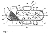
Figure 1 is a top elevational view of a sanitary napkin in accordance with the present invention; and -
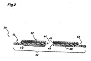
Figure 2 is a cross-sectional view taken along the longitudinal axis of the sanitary napkin shown inFigure 1 . - Referring to
Figure 1 there is shown an embodiment of the present invention, a femininesanitary napkin 20. Thesanitary napkin 20 has amain body 22 with a firsttransverse end 26 and an opposite secondtransverse end 28 defining therebetween a length. Themain body 22 also has two longitudinal sides, namely alongitudinal side edge 30 and an oppositelongitudinal side edge 32 defining therebetween a width. Themain body 22 has a centrallongitudinal axis 34 that is an imaginary line bisecting thesanitary napkin 20 in two substantially identical halves. Themain body 22 also has an imaginarytransverse centerline 36 perpendicular to the centrallongitudinal axis 34. - As depicted in
Figure 2 , which is a cross sectional view of thesanitary napkin 20 inFigure 1 , themain body 22 is of a laminate construction and preferably comprises a liquidpermeable cover layer 42, anabsorbent core 44, and a liquidimpervious barrier layer 50. Theabsorbent core 44 may comprise a single layer, or alternatively, theabsorbent core 44 preferably has two components as shown, including a firstabsorbent layer 46 and a secondabsorbent layer 48. The firstabsorbent layer 46 is adapted to rapidly acquire liquid from thecover layer 42 and to hold the liquid until the secondabsorbent layer 48 can absorb and retain the absorbed liquid. When theabsorbent core 44 comprises a single layer, it is preferably the secondabsorbent layer 48 as described hereinbelow. - In accordance with the present invention, a
preferential bending zone 45 is included in each of thetransverse end regions sanitary napkin 20. Thepreferential bending zones 45 are located solely in thetransverse end regions sanitary napkin 20 and there are no preferential bending zones located in the central region of the sanitary napkin. The terminology "central region" of the sanitary napkin, as used herein is that region of the sanitary napkin that registers with the vaginal opening of the user when the sanitary napkin is worn. Thetransverse end regions transverse ends napkin 20 and the central region, respectively. It has been discovered that when thesanitary napkin 20 is provided with apreferential bending zone 45 in eachtransverse end region main body 22 of thesanitary napkin 20 that extends obliquely with respect to thelongitudinal axis 34 of the napkin, the effect is to stiffen the napkin in both a lateral and longitudinal direction by virtue of it orientation with relation to the longitudinal axis and thus enhance the napkin's ability to resist bunching. The result is an engineered rigidity that creates resistance to lateral compression in thetransverse end regions sanitary napkin 20 and at the same time does not make the napkin overly stiff. Advantageously, thetransverse end regions sanitary napkin 20 are able to independently twist along their respective longitudinal axes while allowing the central region 70 to adapt to the contours of the wearer's body and thereby allow the sanitary napkin conform to the shape of the wearer's body, providing the sanitary napkin with enhanced comfort and stability in use. - Referring again to
Figure 1 , themain body 22 of thesanitary napkin 20 is provided with apreferential bending zone 45 in each transverse end region of the sanitary napkin. Thepreferential bending zone 45 crosses the longitudinal axis of the sanitary napkin. This obliquely extendingpreferential bending zone 45 extends from one longitudinal side area of thesanitary napkin 20 to the opposite longitudinal side area, crossing the imaginary centrallongitudinal axis 34 of thesanitary napkin 20. The obliqueness requirement of thepreferential bending zone 45 is met as long as a substantial segment of thepreferential bending zone 45 is oblique with relation to the centrallongitudinal axis 34. The segment that is oblique crosses the longitudinal axis. A preferred method of creating the preferential bending zones is to mechanically emboss the surface of the main body of the sanitary napkin, resulting in a series of local densifications of the absorbent material. An advantage afforded by forming the oblique preferential bending zones as embossed channels is that they contribute to a more uniform distribution of bodily fluids along the surface of the sanitary napkin by channeling the fluids away from the point of contact. The sanitary napkin is also more efficient in collecting bodily fluids, since a larger surface area is available for contact with the fluids than when bunching occurs. - The
preferential bending zone 45 can be straight, arcuate, form a repeating pattern, such as a wavy pattern or a zigzag pattern or a combination of these shapes. When a repeating pattern is present in a segment of thepreferential bending zone 45, the obliqueness of that segment is determined by considering an imaginary line that is contained within the repeating pattern and that either forms or at least approximates a line of symmetry for the pattern. The transverse ends of the sanitary napkin may be provided with a plurality of preferential bending zones in a variety of patterns, including a plurality of substantially parallel lines, a plurality of parallel and converging lines, etc. In a preferred embodiment, when the plurality of preferential bending zones are in the form of parallel lines, the spacing between the parallel lines is about 2 cm. In preferred embodiment, thesanitary napkin 20 has a plurality of preferential bending zones that converge towards a common point of intersection to create the appearance of a "basket weave" type pattern extending over a major portion of the longitudinal dimension of the transverse end regions of the main body of the sanitary napkin. In accordance with this preferred embodiment of the invention, the sanitary napkin has a plurality of obliquely extendingpreferential bending zones 45 that are disposed across the surface of thetransverse end regions main body 22 of thesanitary napkin 20 wherein adjacent preferential bending zones converge towards each other. Under this embodiment, the oblique preferential bending zones are arcuate. - The
preferential bending zone 45 may optionally intersect with another adjacentpreferential bending zone 45 in the basket weave pattern. The preferential bending zones are oblique over 100% of their length with relation to the longitudinal axis and more preferably they are arcuate along a substantial portion of their length. In a variant the oblique preferential bending zones could also be straight or form a repeating pattern, such as a wavy pattern or a zigzag pattern. The preferential bending zones are created in thecover layer 42 andabsorbent core 44. Eachpreferential bending zone 45 extends generally along an angle of 45 degrees with respect to the longitudinal axis or lateral axis of the main body of the sanitary napkin. The pattern is designed such that eachpreferential bending zone 45 intersects at least two other preferential bending zones. Also, eachpreferential bending zone 45 extends from one longitudinal side area of the sanitary napkin to the opposite longitudinal side area, crossing the imaginary longitudinal axis of the sanitary napkin. A longitudinal side area is defined as a portion of the sanitary napkin that extends inwardly from and includes a respectivelongitudinal side edge sanitary napkin 20. This dimension is measured without taking into account the flaps. It is the maximal distance defined between the longitudinal side edges 30, 32 of thesanitary napkin 20. It is preferred that thepreferential bending zone 45 does not extend to the longitudinal sides of the sanitary napkin and are spaced inward from each side edge by at least 2 mm, preferably spaced inward by at least 5 mm. In a most preferred embodiment, thepreferential bending zone 45 is spaced inward from the longitudinal side edges of theabsorbent core 44. - In accordance with another embodiment of the present invention, the central region is provided with a longitudinally extending hinge adjacent to and inward from each longitudinal side edge of the sanitary napkin. It is important to note that the longitudinally extending hinges in the central region of the
sanitary napkin 20 are distinct from thepreferential bending zones 45 in the transverse end regions of the napkin in that the longitudinally extending hinges do not extend obliquely across the centrallongitudinal axis 34. Rather, the longitudinally extending hinges extend longitudinally adjacent the longitudinal side edges 30, 32, respectively. Thus, while the longitudinally extending hinges may optionally have obliquely extending portions, these portions do not cross the central longitudinal axis. It is preferred that no portion of the longitudinally extending hinge cross the centrallongitudinal axis 34. - In a more preferred embodiment, the central region is provided with two longitudinally extending hinges. The longitudinally extending hinges are located substantially within the central region adjacent each respective longitudinal edge, each hinge being adapted to provide a longitudinally extending preferential bending axis. The hinges are spaced apart along at least a portion of their length. It is preferred that at least one hinge has a radius of curvature and an adjacent hinge is substantially straight. As shown in
Fig 1 afirst hinge 75 has a radius of curvature and is closer to the centrallongitudinal axis 34 than thesecond hinge 76 that is substantially straight. Alternatively, the first hinge may be substantially straight (not shown) and is closer to the centrallongitudinal axis 34 than thesecond hinge 76 that has a radius of curvature. Thefirst hinge 75 is generally separated from thesecond hinge 76 along a substantial portion of their respective lengths but may optionally be co-terminus and also may optionally contact one another at their respective distal ends. - In a preferred embodiment, each hinge has a radius of curvature and preferably one hinge has a radius of curvature greater than an adjacent hinge. The
first hinge 75, which is closer to the centrallongitudinal axis 34 than thesecond hinge 76, may have a lower radius of curvature than the second hinge. Alternatively, thefirst hinge 75 may have a greater radius of curvature than thesecond hinge 76. - In any of the foregoing embodiments, it has been found that by providing a sanitary napkin with at least two substantially centrally located longitudinal hinges adjacent each longitudinal side edge of the main body, wherein one hinge has a greater radius of curvature than the adjacent hinge provides an optimum fit to a wide variety of wearers' anatomies. That is the multiple longitudinal hinges create a sanitary napkin that has multiple modes of controlled deformation that enables the napkin to conform to the entire range of user anatomies. Moreover, the multiple longitudinal hinges control bunching rather than prevent bunching to create greater comfort, fit to the anatomy and discretion.
- The combination of multiple hinges with differences in curvature provides a controlled deformation in an enhanced manner. A hinge having a lower radius of curvature (less straight) has more lateral stability than a hinge having a higher radius of curvature (more straight) since it has more lateral components and can thus resist transverse compression. The hinge with a higher radius of curvature will have a greater tendency to bend relative to a hinge with a lower radius of curvature. Thus the hinge with the lower radius of curvature has a greater resistance to bunching and will maintain the napkin is a flatter (i.e. more planar) configuration in use. The combination of these two hinge types along each longitudinal side of the main body enables the main body to conform to a wide range of user anatomies.
- Longitudinally extending hinges 75, 76 may include any material in an amount sufficient to impart additional structural rigidity relative to adjacent regions. Examples of suitable material to form the longitudinally extending hinges 75, 76 comprise a sphagnum-moss containing insert, a densified channel, strips of polymeric foam, and the like and combinations thereof. In a preferred embodiment, each longitudinally extending
hinge Figure 1 . The density of the channels is at least two times the density of the adjacent non-densified regions and is preferably from two to ten times the density of the adjacent regions of the absorbent core. The density of the channels is preferably at least 0.5 g/cc. The longitudinally extending hinges 75, 76 are adapted to maintain the central region of the main body portion in a relatively flat profile along the longitudinal axis and resists bending transverse to that axis. A central region having a longitudinally extending hinges 75, 76 has been found to effectively conform to the body in that region, resist asymmetrical deformation due to the application of laterally compressive forces and thereby prevents leakage of liquid from the main body portion. That is, since the hinges effectively control deformation, when subjected to laterally compressive forces of a user's thighs, the sanitary napkin will deform symmetrically about the central longitudinal axis rather than deforming randomly across its width. - The
cover layer 42 may be any soft, flexible material that is liquid permeable and is capable of rapidly absorbing body liquid and transporting it away from the body and the point of deposition'.. In a preferred embodiment, thecover layer 42 is a relatively low density, bulky, high-loft non-woven web material. The non-woven web material may be composed of only one type of fiber, such as polyester or polypropylene or it may be composed of bi-component or conjugate fibers having a low melting point component and a high melting point component. The fibers may be selected from a variety of natural and synthetic materials such as nylon, polyester, rayon (in combination with other fibers), cotton, acrylic fiber and the like and combinations thereof. Bi-component fibers may be made up of a polyester core and a polyethylene sheath. The use of appropriate bi-component materials results in a fusible non-woven fabric. Using a fusible fabric increases the ease with which thecover layer 42 may be mounted to the adjacent first absorbent layer and/or to thebarrier layer 50. - The
cover layer 42 preferably has a relatively high degree of wettability, although the individual fibers comprising the cover may not be particularly hydrophilic. Advantageously, the fibers which make up thecover layer 42 should not lose their physical properties when they are wetted, in other words they should not collapse or lose their resiliency when subjected to water or body liquid. Thecover layer 42 may be treated to allow liquid to pass through it readily. Thecover layer 42 also functions to transfer the liquid quickly to the other layers of theabsorbent core 44. Thus, thecover layer 42 is advantageously wettable, hydrophilic and porous. When composed of synthetic hydrophobic fibers such as polypropylene or bi-component fibers, thecover layer 42 may be treated with a surfactant to impart the desired degree of wettability. - Alternatively, the
cover layer 42 can also be made of an apertured polymer film wherein the apertures form large pores that are capable of quickly transferring body liquid to the inner layers of the absorbent core. The film may be a single !ayer film such as polyethylene or polypropylene film or alternatively may be formed as a multi-layered co-extruded film. Suitable apertured films that are suitable for use in the present invention are well known to those skilled in the art. - The
cover layer 42 may be affixed to the remainder of theabsorbent core 44 in order to aid in promoting liquid transport by fusing the cover to the subjacent layer. Such affixation may be effected locally, at a plurality of sites or over the entire contact surface ofcover layer 42 withabsorbent core 44 using such techniques as adhesive, embossing, heat-bonding, ultrasonic bonding, and the like. - Adjacent to the
cover layer 42 on its inner side and bonded to thecover layer 42 is a firstabsorbent layer 46 that forms part of theabsorbent core 44. The firstabsorbent layer 46 provides the means of receiving body liquid from thecover layer 42 and holding it until an underlying second absorbent layer has an opportunity to absorb the liquid. - The first
absorbent layer 46 is, preferably, more dense than and has a larger proportion of smaller pores than thecover layer 42. These attributes allow the firstabsorbent layer 46 to contain body liquid and hold it away from the outer side of thecover layer 42, thereby preventing the liquid from rewetting thecover layer 42 and its surface. However, the firstabsorbent layer 46 is, preferably, not so dense as to prevent the passage of the liquid through thelayer 46 into the underlying secondabsorbent layer 48. These types of absorbent layers are commonly known as liquid transfer layers or acquisition layers. - The first
absorbent layer 46 may be composed of fibrous materials, such as wood pulp, polyester, rayon, polypropylene, polyethylene, or the like, or combinations thereof. The firstabsorbent layer 46 preferably comprises thermoplastic fibers that are thermobonded together for the purpose of stabilizing the layer and maintaining its structural integrity. The firstabsorbent layer 46 may be treated with surfactant on one or both sides in order to increase its wettability, although generally the firstabsorbent layer 46 is relatively hydrophilic and may not require treatment. The firstabsorbent layer 46 is preferably bonded on both sides to the adjacent layers, i.e. thecover layer 42 and an underlying secondabsorbent layer 48. - Immediately subjacent to and bonded to the first
absorbent layer 46 is the secondabsorbent layer 48. In a preferred embodiment, the firstabsorbent layer 46 has a central width that is at least about the same as the central width of the secondabsorbent layer 48. In another embodiment, the firstabsorbent layer 46 has a central width that exceeds the central width of the secondabsorbent layer 48. The term "central width" refers to a specific area of a layer, such as an absorbent layer determinable as follows. A reference point on the sample layer that is disposed beneath the center of the vaginal orifice, when worn, is located. A plane parallel to thetransverse centerline 36 and 3.75 centimeters forward from the reference point in the direction of the wearer's mons pubis is located. Another plane parallel to thelateral centerline 36 and 5.0 centimeters rearward from the reference point in the direction of the wearer's buttocks is also located. The greatest flat-out, uncompressed, unmanipulated, lateral width of the sample layer between the two planes is the absorbent width of the sample layer. In a preferred embodiment, the central width of the firstabsorbent layer 46 is greater than about 64mm. The central width of the absorbent core, when the absorbent core includes a plurality of absorbent layers is the central width of the layer of the absorbent core that has the largest central width. - In a preferred embodiment, the second
absorbent layer 48 is a blend or mixture of cellulosic fibers and superabsorbent polymer particles. For the purposes of the present invention, the term "superabsorbent polymer" or "superabsorbent particle" (both terms being commonly used interchangeably are hereinafter referred to as "SAP") refers to materials which are capable of absorbing and retaining at least about 10 times their weight in body liquids under a 0.5 psi pressure. Suitable SAP for use in the present invention may be inorganic or organic crosslinked hydrophilic polymers, such as polyvinyl alcohols, polyethylene oxides, crosslinked starches, guar gum, xanthan gum, and the like. The particles may be in the form of a powder, grains, granules, or fibers. - In a specific example, the second
absorbent layer 48 is a material containing from about 40 weight percent to about 95 weight percent cellulosic fibers; and from about 5 weight percent to about 60 weight percent SAP. The material has a water content of less than about 10 weight percent. As used herein, the phrase "weight percent" means weight of substance per weight of final material. By way of example, 10 weight percent SAP means 10 g/m2 SAP per 100g/m2 basis weight of the material. - Cellulosic fibers that can be used in the second
absorbent layer 48 are well known in the art and include wood pulp, cotton, flax and peat moss. Wood pulp is preferred. Pulps can be obtained from mechanical or chemimechanical, sulfite, kraft, pulping reject materials, organic solvent pulps, etc. Both softwood and hardwood species are useful. Softwood pulps are preferred. It is not necessary to treat cellulosic fibers with chemical debonding agents, cross-linking agents and the like for use in the present material. - In a specific example the second
absorbent layer 48 is a material containing from about 50 to about 95 weight percent cellulosic fibers and, more specifically from about 60 to about 80 weight percent cellulosic fibers. Such a material may contain from about 5 to about 60 weight percent SAP, preferably from about 20 to about 55 weight percent SAP, even more preferably from about 30 to about 45 weight percent SAP, and most preferably about 40 weight percent SAP. - The second
absorbent layer 48 can be manufactured by using air-laying means well known in the art. Cellulosic fibers (e.g., wood pulp fibers) are processed using a hammer mill to individualize the fibers. The individualized fibers may be blended with SAP granules in a blending core and pneumatically conveyed into a series of forming heads. The blending and distribution of fibers and SAP granules can be controlled separately for each forming head. Fibers (and SAP) from each forming chamber are deposited by vacuum onto a forming surface thus forming a layered absorbent web. The web is subsequently compressed using calenders to achieve desirable density. The densified web is wound into a roll using conventional winding equipment. The forming surface may be covered with tissue paper to reduce the loss of material. The tissue paper layer can be removed prior to calendering or incorporated into the formed material. In a possible variant, the firstabsorbent layer 46 can be formed integrally with the secondabsorbent layer 48 to provide a unitizedabsorbent core 44. - The second
absorbent layer 48 of the present invention is of high density and in a specific example has a density of greater than about 0.25 g/cc, Specifically, the secondabsorbent layer 48 may have a density in the range of from about 0.30 g/cc to about 0.50 g/cc. More specifically, the density is from about 0.30 g/cc to about 0.45 g/cc and, even more specifically from about 0.35 g/cc to about 0.40 g/cc. - Air-laid absorbents are typically produced with a low density. To achieve higher density levels, such as the examples of the second
absorbent layer 48 given above, the air-laid material is-compacted using calenders as is well known in the art. Typically such compacting is carried out at a temperature of about 100 degrees C and a load of about 130 Newtons per millimeter. In one embodiment the secondabsorbent layer 48 has a ratio of Gurley stiffness, measured in milligrams (mg) to density, measured in grams per cubic centimeter (g/cc), of less than about 3700. In a specific example, that ratio of Gurley stiffness to density is less than about 3200 and, more specifically, less than about 3000. - Gurley stiffness is one of many indices of softness. Gurley stiffness measures the bendability or flexibility of absorbent materials. The lower the Gurley stiffness value, the more flexible the material. The Gurley stiffness values are measured using a Gurley Stiffness Tester (Model No. 4171 E), manufactured by Gurley Precision Instruments of Troy, N.Y. The instrument measures the externally applied moment required to produce a given deflection of a test strip of specific dimensions fixed at one end and having a concentrated load applied to the other end. The results are obtained in "Gurley Stiffness" values in units of milligrams.
- The second
absorbent layer 48 is strong in light of its softness. Pad integrity is a well-known measurement of absorbent material strength. In a specific embodiment the secondabsorbent layer 48 demonstrates strength (high pad integrity) over a wide range of densities. In a specific example the secondabsorbent layer 48 has a pad integrity, measured In Newtons (N), to density (g/cc) ratio of greater than about 25.0. In a more specific example, that ratio is greater than about 30.0 and, could even be greater than about 35.0. The pad integrity is a test performed on an Instron Universal Testing Machine. Essentially, the test measures the load required to pierce through the test sample, as described In the PFI Method of 1981. A test sample having dimensions of 50 mm by 50 mm is clamped on the Instron with a suitable fastening device. A 20 mm diameter piston traveling at the rate of 50 mm/min punctures the stationary sample. The force required to puncture the sample is measured in Newtons (N). - The second
absorbent layer 48 has a basis weight in the range of from about 100 g/m2 to about 700 g/m2. In a specific example, the basis weight ranges from about 150 g/m2 to about 350 g/m2 . Preferably the basis weight ranges from about 200 g/m2 to about 300 g/m2 and, more preferably, to about 250 g/m2. - The second
absorbent layer 48 can be formed as three or four lamina or strata. Those strata include a bottom layer, one or two middle layers and a top layer. Specific examples of three and four layer material are set forth below. The SAP can be included in any or all of the layers. The concentration (weight percent) of SAP in each layer can vary as can the nature of the particular SAP. - The second
absorbent layer 48 has a thickness that varies from about 0,5 mm to about 2.5 mm. In a preferred embodiment, the thickness is from about 1.0 mm to about 2.0 mm and, even more preferably from about 1.25 mm to about 1.75 mm. - One embodiment of the second
absorbent layer 48 particularly well suited for use in thesanitary napkin 20 is depicted in Figure 6. Such secondabsorbent layer 48 has a basis weight of from about 200 g/m2 to about 350 g/m2 and a density between about 0.3 g/cc and 0.5 g/cc. In a specific example, the density is from about 0.3 g/cc to about 0.45 g/cc and, more specifically about 0.3 g/cc to about 0.4 g/cc. - The second
absorbent layer 48 may be air-laid as three strata: a bottom layer of pulp (without superabsorbent) with a basis weight of about 25 g/m2; a middle layer with a basis weight of about 150 g/m2 and which contains from about 10 to about 30 g/m2 superabsorbent and fmm about 120 g/m2 to about 140 g m2 pulp; and a top layer of pulp (without superabsorbent) with a basis weight of about 25 g/m2. Relative to the total basis weight of the secondabsorbent layer 48, the level of superabsorbent ranges from about 5 to about 15 weight percent (g/m2 of superabsorbent per g/m2 material). In a specific example, the level of superabsorbent is from about 7.5 weight percent to about 12.5 weight percent of the material. More specifically, the material contains about 10 weight percent of superabsorbent. Thus, the middle layer of the material could contain from about 15 g/m2 to about 25 g/m2 superabsorbent and from about 125 g/m2 to about 135 g/m2 pulp and, more specifically about 20 g/m2 superabsorbent and about 130 g/m2 pulp. The middle layer containing pulp and superabsorbent can be laid down as a homogeneous blend or as a heterogeneous blend wherein the level of superabsorbent varies with proximity to the bottom layer. - In another embodiment, the second
absorbent layer 48 may be air-laid as four strata. In this embodiment, the middle layer referred to above is replaced with two middle layers: a first middle layer adjacent the top layer and a second middle layer adjacent the bottom layer. Each of the first and second middle layers independently comprises from about 10 to about 30 g/m2 superabsorbent and from about 40 g m2 to about 65 g/ m2 pulp. When it is desired to keep absorbed liquid away from thecover layer 42 the amount of superabsorbent in the first and second middle layers is adjusted such that there is a higher level of superabsorbent in the second middle layer. The superabsorbent in the first and second middle layers can be the same or a different superabsorbent. - Underlying the
absorbent core 44 is a liquidimpermeable barrier layer 50 comprising liquid-impervious film material so as to prevent liquid that is entrapped in theabsorbent core 44 from egressing the sanitary napkin and staining the wearer's undergarment. Thebarrier layer 50 is made preferably of polymeric film. - The
cover layer 42 and thebarrier layer 50 are joined along their marginal portions so as to form an enclosure or flange seal that maintains theabsorbent core 44 captive. The flange seal may be made by means of adhesives, heat-bonding, ultrasonic bonding, radio frequency sealing, mechanical crimping, and the like and combinations thereof. The peripheral seal line is shown inFigure 1 by thereference numeral 52. - The
sanitary napkin 20, as shown inFigure 1 has twoflaps longitudinal sides flaps flaps cover layer 42 and thebarrier layer 50. These integral extensions are joined to one another along their marginal seal portions by adhesives, heat-bonding, ultrasonic bonding, radio frequency sealing, mechanical crimping, and the like and combinations thereof. Most preferably, such joining is made at the same time thecover layer 42 and thebarrier layer 50 are bonded to one another to enclose theabsorbent core 44. Alternatively, the flaps may include absorbent material between thecover layer 42 and thebarrier layer 50 extensions. Such absorbent material may be an extension of the firstabsorbent layer 46, the secondabsorbent layer 48 or both. - Referring to
Figure 2 , in order to enhance the stability of the sanitary napkin, the garment facing surface of thebarrier layer 50 is provided with positioningadhesive material 58, typically hot-melt adhesive material capable of establishing a temporary bond with the undergarment material. A suitable material is the composition designated HL-1491 XZP commercially available from H.B. Fuller Canada, Toronto, Ontario, Canada. The positioning adhesive 58 may be applied to the garment-facing surface of thebarrier layer 50 in various patterns, including complete adhesive coverage, parallel longitudinal lines, a line of adhesive following the perimeter of the structure, transverse lines of adhesive or the like. - Standard release paper (not shown) covers the
positioning adhesive 58 before the napkin is used to prevent the unwanted adherence of the napkin to itself or foreign objects. The release paper is of conventional construction (e.g. silicone coated wet-laid Kraft wood pulp. - The
main body 22 of thesanitary napkin 20 has an average thickness that is generally less than about 5 mm, preferably less than 3 mm and more preferably is less than 2 mm. In a particularly preferred embodiment, themain body 22 of thesanitary napkin 20 has a thickness of about 2.8 mm. - An apparatus that is suitable to measure the thickness of the sanitary napkin is a footed dial (thickness) gauge with stand, available from Ames, with a 2" diameter foot and a readout accurate to 0.001". A digital type apparatus is preferred. If the sanitary napkin sample is individually folded and wrapped, the sample is unwrapped and carefully flattened by hand. The release paper is removed from the sample and it is repositioned back gently across the positioning adhesive lines so as not to compress the sample, ensuring that the release paper lies flat across the sample. Flaps (if any) are not considered when taking the thickness reading of the sample.
- The foot of the gauge is raised and the sample Is placed on the anvil such that the foot of the gauge is approximately centered to the sample (or in the location of interest on the sample of interest). When lowering the foot, care is taken to avoid allowing the foot to "drop" or that undue force is not applied. A load of 0.07 p.s.i.g. is applied to the sample and the read out is allowed to stabilize for'approximately 5 seconds. The thickness reading is then taken. The thickness of the release paper covering the positioning adhesive is deducted from the total thickness.
- The flexural resistance of the sanitary napkin is preferably in the range from about 200g to about 800 g. The flexural resistance of a sanitary napkin is measured by peak bending stiffness. Peak bending stiffness is determined by a test that is modeled after the ASTM D 4032-82 CIRCULAR BEND PROCEDURE, the procedure being considerably modified and performed as follows. The CIRCULAR BEND PROCEDURE is a simultaneous multi-directional deformation of a material in which one face of a specimen becomes concave and the other face becomes convex. The CIRCULAR BEND PROCEDURE gives a force value related to flexural resistance, simultaneously averaging stiffness in all directions.
- The apparatus necessary for the CIRCULAR BEND PROCEDURE is a modified Circular Bend Stiffness Tester, having the following parts:
- 1. A smooth-polished steel plate platform which is 102.0 mm by 102.0 by 6.35 mm having an 18.75 mm diameter orifice. The lap edge of the orifice should be at a 45 degree angle to a depth of 4.75 mm;
- 2. A plunger having an overall length of 72.2 mm, a diameter of 6.25 mm, a ball nose having a radius of 2.97 mm and a needle-point extending 0.88 mm therefrom having a 0.33 mm base diameter and a point having a radius of less than 0.5 mm, the plunger being mounted concentric with the orifice and having equal clearance on all sides. Note that the needle-point is merely to prevent lateral movement of the test specimen during testing. Therefore, if the needle-point significantly adversely affects the test specimen (for example, punctures an inflatable structure), than the needle-point should not be used. The bottom of the plunger should be set well above the top of the orifice plate. From this position, the downward stroke of the ball nose is to the exact bottom of the plate orifice:
- 3. A force-measurement gauge and more specifically an Instron inverted compression load cell. The load cell has a load range of from about 0.0 to about 2000.0 g;
- 4. An actuator and more specifically the Instron Model No. 1122 having an inverted compression load cell. The Instron 1122 is made by the Instron Engineering Corporation, Canton, Mass.
- In order to perform the procedure for this test, as explained below, five representative sanitary napkins are necessary. From one of the five napkins to be tested, some number "Y" of 37.5 mm by 37.5 mm test specimens are cut. Specimens having portions in which a cover layer is joined directly to a barrier layer or which are a laminate of a cover layer, and a barrier layer without any component of the absorbent core, should not be tested. This test is more concerned with the overall flexibility of the sanitary napkin and not merely the peripheral portions thereof and, therefore, the flexibility of the present invention is more concerned with the flexibility of the absorbent portions of the sanitary napkin.
- The test specimens should not be folded or bent by the test person, and the handling of specimens must be kept to a minimum and to the edges to avoid affecting flexural-resistance properties. From the four remaining sanitary napkins, an equal number "Y" of 37.5 mm by 37.5 mm specimens, identical to the specimens cut from the first napkin, are cut. Thus, the test person should have "Y" number of sets of five identical specimens.
- The procedure for the CIRCULAR BEND PROCEDURE is as follows. The specimens are conditioned by leaving them in a room that is 21 degree Celsius plus or minus 1 degree Celsius. and 50% plus or minus 2.0 % relative humidity for a period of two hours. The test plate is leveled. The plunger speed is set at 50.0 cm per minute per full stroke length. A specimen is centered on the orifice platform below the plunger such that the cover layer of the specimen is facing the plunger and the barrier layer of the specimen is facing the platform. The indicator zero is checked and adjusted, if necessary. The plunger is actuated. Touching the specimen during the testing should be avoided. The maximum force reading to the nearest gram is recorded. The above steps are repeated until all five of the identical specimens have been tested.
- The peak bending stiffness for each specimen is the maximum force reading for that specimen. Remember that "Y" number of sets of five identical specimens were cut. Each set of five identical specimens is tested and the five values received for that set are averaged. Thus, the test person now has an average value for each of the "Y" sets tested. The flexural resistance for a sanitary napkin is the greatest of the average peak bending stiffness.
- The above-described embodiment of the
sanitary napkin 20 may be fabricated in a conventional manner in accordance with conventional techniques. Specifically, a laminate structure comprising the following layers of material In a top-to-bottom order: a cover layer material; an absorbent layer material; a second absorbent layer material (manufactured as described above); and finally a barrier layer material. Some of the materials are necessarily not continuous within the laminate structure, and where such is the case, they are positioned precisely, one with respect to another, in the relationship they will occupy in the final products. The cover layer material and the barrier layer material are then bonded together by applying pressure, optionally in combination with adhesive, in the appropriate positions, and what will become the peripheral seal is created. The sealed structure is then severed by conventional means (i.e. die-cutting, liquid-jet cutting, or by laser) from the web to create a discrete article. - Applications of the product and methods of the present invention for sanitary uses can be accomplished by any sanitary protection, and absorbent techniques as are presently or prospectively known to those skilled in the art. Thus, it is intended that the present application cover the modifications and variations of this invention provided that they come within the scope of the appended claims and their equivalents.
Claims (12)
- A sanitary napkin (20) adapted to be worn in a crotch portion of an undergarment of a wearer, said sanitary napkin (20) having a main body (22) including a liquid permeable cover layer (42), a liquid impermeable barrier layer (50) and an absorbent core (44) intermediate the cover layer (42) and barrier layer (50), the main body (22) having two longitudinal side edges (3 0, 32) defining therebetween a width and two spaced apart transverse ends (26, 28) defining therebetween a length, an imaginary central longitudinal axis (34) that bisects the main body (22) into two equal halves, a transverse axis (36) that is perpendicular to the longitudinal axis (34), a first transverse end region, an opposite second transverse end region (66, 68) and a central region intermediate the first and second transverse end regions, characterized in that the first transverse end region and the second transverse end region (66, 68) each having a respective preferential bending zone (45) extending obliquely in relation to the longitudinal axis (34), wherein the preferential bending zone (45) provides a bending axis that is oblique with respect to the central longitudinal axis (34), said preferential bending zone (45) extending from one longitudinal side area of the sanitary napkin (20) to an opposite longitudinal side area and crossing the central longitudinal axis (34) of the sanitary napkin (20), wherein each preferential bending zone (45) is located solely in a respective transverse end region (66,68) and does not extend into the central region, wherein said preferential bending zone (45) is an embossed channel which compresses said liquid permeable cover layer (42) and said absorbent core (44).
- A sanitary napkin (20) as defined in claim 1, wherein said sanitary napkin has a thickness less than 5 mm.
- A sanitary napkin (20) according to claim 1 comprising a plurality of preferential bending zones (45) spaced apart from one another.
- A sanitary napkin (20) according to claim 3, wherein adjacent preferential bending zones (45) converge towards each other and wherein said oblique preferential bending zones are arcuate.
- A sanitary napkin (20) according to claim 3, wherein said preferential bending zones (45) intersect each other.
- A sanitary napkin (20) according to claim 5, wherein each preferential bending zone (45) intersects at least two other preferential bending zones (45).
- A sanitary napkin (20) according to claim 1, wherein said preferential bending zone (45) is arcuate.
- A sanitary napkin (20) according to claim 1, wherein each longitudinal side area has a width that is 25% of the maximal transverse dimension of the sanitary napkin (20).
- A sanitary napkin (20) according to claim 1, wherein the central region has a pair of spaced apart longitudinally extending hinges (75, 76), one hinge being adjacent to and inward from each longitudinal side edge.
- A sanitary napkin (20) according to claim 1, wherein the central region has two pairs of spaced apart longitudinally extending embossed hinges (75, 76), one pair of hinges being adjacent to and inward from each longitudinal side edge (30, 32).
- A sanitary napkin (20) according to claim 1, wherein the central region has at least two longitudinal hinges (75, 76) adjacent each longitudinal side edge (30, 32) of the main body (22), wherein one hinge has a greater radius of curvature than the adjacent hinge.
- A sanitary napkin according to claim 9, wherein said hinges (75, 76) are embossed channels which compress said absorbent core (44).
Applications Claiming Priority (2)
| Application Number | Priority Date | Filing Date | Title |
|---|---|---|---|
| US10/261,319 US6953451B2 (en) | 2002-09-30 | 2002-09-30 | Thin comfortable sanitary napkin having reduced bunching |
| US261319 | 2008-10-30 |
Publications (3)
| Publication Number | Publication Date |
|---|---|
| EP1402863A1 EP1402863A1 (en) | 2004-03-31 |
| EP1402863B1 true EP1402863B1 (en) | 2010-01-20 |
| EP1402863B2 EP1402863B2 (en) | 2013-07-24 |
Family
ID=31977943
Family Applications (1)
| Application Number | Title | Priority Date | Filing Date |
|---|---|---|---|
| EP03022174.1A Expired - Fee Related EP1402863B2 (en) | 2002-09-30 | 2003-09-30 | Thin comfortable sanitary napkin having reduced bunching |
Country Status (12)
| Country | Link |
|---|---|
| US (1) | US6953451B2 (en) |
| EP (1) | EP1402863B2 (en) |
| KR (1) | KR20040029266A (en) |
| CN (1) | CN1301700C (en) |
| AR (1) | AR041430A1 (en) |
| AU (1) | AU2003248449C1 (en) |
| BR (2) | BRPI0304291B8 (en) |
| CA (1) | CA2443173C (en) |
| DE (1) | DE60331030D1 (en) |
| MX (1) | MXPA03008941A (en) |
| RU (1) | RU2003129092A (en) |
| ZA (1) | ZA200307584B (en) |
Cited By (12)
| Publication number | Priority date | Publication date | Assignee | Title |
|---|---|---|---|---|
| US8979815B2 (en) | 2012-12-10 | 2015-03-17 | The Procter & Gamble Company | Absorbent articles with channels |
| US9060904B2 (en) | 2007-06-18 | 2015-06-23 | The Procter & Gamble Company | Disposable absorbent article with sealed absorbent core with substantially continuously distributed absorbent particulate polymer material |
| US9066838B2 (en) | 2011-06-10 | 2015-06-30 | The Procter & Gamble Company | Disposable diaper having reduced absorbent core to backsheet gluing |
| US9072634B2 (en) | 2007-06-18 | 2015-07-07 | The Procter & Gamble Company | Disposable absorbent article with substantially continuously distributed absorbent particulate polymer material and method |
| US9216116B2 (en) | 2012-12-10 | 2015-12-22 | The Procter & Gamble Company | Absorbent articles with channels |
| US9216118B2 (en) | 2012-12-10 | 2015-12-22 | The Procter & Gamble Company | Absorbent articles with channels and/or pockets |
| US9326896B2 (en) | 2008-04-29 | 2016-05-03 | The Procter & Gamble Company | Process for making an absorbent core with strain resistant core cover |
| US9375358B2 (en) | 2012-12-10 | 2016-06-28 | The Procter & Gamble Company | Absorbent article with high absorbent material content |
| US9468566B2 (en) | 2011-06-10 | 2016-10-18 | The Procter & Gamble Company | Absorbent structure for absorbent articles |
| US9492328B2 (en) | 2011-06-10 | 2016-11-15 | The Procter & Gamble Company | Method and apparatus for making absorbent structures with absorbent material |
| US9532910B2 (en) | 2012-11-13 | 2017-01-03 | The Procter & Gamble Company | Absorbent articles with channels and signals |
| US11957551B2 (en) | 2013-09-16 | 2024-04-16 | The Procter & Gamble Company | Absorbent articles with channels and signals |
Families Citing this family (52)
| Publication number | Priority date | Publication date | Assignee | Title |
|---|---|---|---|---|
| JP2004174209A (en) * | 2002-09-30 | 2004-06-24 | Uni Charm Corp | Disposable body fluid absorbent pad |
| JP4324375B2 (en) * | 2002-12-27 | 2009-09-02 | ユニ・チャーム株式会社 | Absorbent article provided with compressed groove and flexible part |
| ATE523180T1 (en) | 2003-02-12 | 2011-09-15 | Procter & Gamble | ABSORBENT CORE FOR AN ABSORBENT ARTICLE |
| DE60323810D1 (en) | 2003-02-12 | 2008-11-13 | Procter & Gamble | Comfortable diaper |
| US7145054B2 (en) * | 2004-02-18 | 2006-12-05 | Kimberly-Clark Worldwide, Inc. | Embossed absorbent article |
| US8211078B2 (en) * | 2005-02-17 | 2012-07-03 | The Procter And Gamble Company | Sanitary napkins capable of taking complex three-dimensional shape in use |
| US8652116B2 (en) * | 2005-09-30 | 2014-02-18 | The Procter & Gamble Company | Preferential bend structure and articles containing said structure |
| WO2007069957A1 (en) * | 2005-12-15 | 2007-06-21 | Sca Hygiene Products Ab | Absorbent article |
| JP5101912B2 (en) * | 2007-03-23 | 2012-12-19 | ユニ・チャーム株式会社 | Absorbent articles |
| US20080281287A1 (en) * | 2007-05-08 | 2008-11-13 | Marcelo Ana Maria Elena R | Sanitary napkin including body-facing protrusions for preventing side leakage and obliquely arranged embossed channels |
| US7942858B2 (en) * | 2007-07-03 | 2011-05-17 | Mcneil-Ppc, Inc. | Sanitary napkin including body-facing protrusions and arcuately arranged embossed channels |
| US20090112173A1 (en) * | 2007-10-30 | 2009-04-30 | Kofi Ayensu Bissah | Absorbent article including an absorbent layer having a plurality of spaced beam elements |
| WO2010030007A1 (en) * | 2008-09-12 | 2010-03-18 | ユニ・チャーム株式会社 | Absorbent article |
| JP5317685B2 (en) * | 2008-12-25 | 2013-10-16 | ユニ・チャーム株式会社 | Absorbent articles |
| US8975466B2 (en) * | 2009-04-29 | 2015-03-10 | Eveready Battery Company, Inc. | Absorbent article including a plurality of longitudinally extending channels |
| EP2329803B1 (en) | 2009-12-02 | 2019-06-19 | The Procter & Gamble Company | Apparatus and method for transferring particulate material |
| US9132048B2 (en) * | 2010-09-28 | 2015-09-15 | Sumitomo Seika Chemicals Co., Ltd. | Water-absorbent sheet structure |
| PL3338751T3 (en) | 2011-06-10 | 2020-04-30 | The Procter & Gamble Company | Absorbent structure for absorbent articles |
| SG195105A1 (en) | 2011-06-10 | 2013-12-30 | Procter & Gamble | Absorbent core for disposable absorbent articles |
| PL2532328T3 (en) | 2011-06-10 | 2014-07-31 | Procter & Gamble | Method and apparatus for making absorbent structures with absorbent material |
| CA2838951C (en) | 2011-06-10 | 2019-07-16 | The Procter & Gamble Company | An absorbent core for disposable diapers comprising longitudinal channels |
| AU2011380943B2 (en) | 2011-11-08 | 2016-10-13 | Kimberly-Clark Worldwide, Inc. | Absorbent article with stabilization member |
| US10639215B2 (en) | 2012-12-10 | 2020-05-05 | The Procter & Gamble Company | Absorbent articles with channels and/or pockets |
| EP2740450A1 (en) | 2012-12-10 | 2014-06-11 | The Procter & Gamble Company | Absorbent core with high superabsorbent material content |
| PL2740452T3 (en) | 2012-12-10 | 2022-01-31 | The Procter & Gamble Company | Absorbent article with high absorbent material content |
| ES2655690T3 (en) | 2013-06-14 | 2018-02-21 | The Procter & Gamble Company | Absorbent article and absorbent core formation channels when wet |
| US9987176B2 (en) | 2013-08-27 | 2018-06-05 | The Procter & Gamble Company | Absorbent articles with channels |
| RU2649546C2 (en) | 2013-08-27 | 2018-04-03 | Дзе Проктер Энд Гэмбл Компани | Absorbent articles with channels |
| JP6169800B2 (en) | 2013-09-16 | 2017-07-26 | ザ プロクター アンド ギャンブル カンパニー | Absorbent articles with channels and labels |
| EP2851048B1 (en) | 2013-09-19 | 2018-09-05 | The Procter and Gamble Company | Absorbent cores having material free areas |
| ES2606320T3 (en) | 2013-12-19 | 2017-03-23 | The Procter & Gamble Company | Absorbent cores that have channel-forming areas and wrapping joints in c |
| US9789009B2 (en) | 2013-12-19 | 2017-10-17 | The Procter & Gamble Company | Absorbent articles having channel-forming areas and wetness indicator |
| EP2905001B1 (en) | 2014-02-11 | 2017-01-04 | The Procter and Gamble Company | Method and apparatus for making an absorbent structure comprising channels |
| ES2643577T3 (en) | 2014-05-27 | 2017-11-23 | The Procter & Gamble Company | Absorbent core with absorbent material design |
| EP2949300B1 (en) | 2014-05-27 | 2017-08-02 | The Procter and Gamble Company | Absorbent core with absorbent material pattern |
| EP2949301B1 (en) | 2014-05-27 | 2018-04-18 | The Procter and Gamble Company | Absorbent core with curved and straight absorbent material areas |
| EP2949302B1 (en) | 2014-05-27 | 2018-04-18 | The Procter and Gamble Company | Absorbent core with curved channel-forming areas |
| JP2018508292A (en) | 2015-03-16 | 2018-03-29 | ザ プロクター アンド ギャンブル カンパニー | Absorbent article with improved core |
| CN107405223B (en) | 2015-03-16 | 2021-03-02 | 宝洁公司 | Absorbent article with improved strength |
| MX2017014428A (en) | 2015-05-12 | 2018-04-10 | Procter & Gamble | Absorbent article with improved core-to-backsheet adhesive. |
| JP6743057B2 (en) | 2015-05-29 | 2020-08-19 | ザ プロクター アンド ギャンブル カンパニーThe Procter & Gamble Company | Absorbent article having channels and wetness indicators |
| EP3167859B1 (en) | 2015-11-16 | 2020-05-06 | The Procter and Gamble Company | Absorbent cores having material free areas |
| EP3238676B1 (en) | 2016-04-29 | 2019-01-02 | The Procter and Gamble Company | Absorbent core with profiled distribution of absorbent material |
| EP3238678B1 (en) | 2016-04-29 | 2019-02-27 | The Procter and Gamble Company | Absorbent core with transversal folding lines |
| WO2018226132A1 (en) | 2017-06-09 | 2018-12-13 | Essity Hygiene And Health Aktiebolag | Disposable hygiene article with improved fit |
| US11123238B2 (en) | 2017-06-09 | 2021-09-21 | Essity Hygiene And Health Aktiebolag | Disposable hygiene article with improved fit |
| WO2018226133A1 (en) | 2017-06-09 | 2018-12-13 | Essity Hygiene And Health Aktiebolag | Disposable hygiene article with improved fit |
| WO2020005124A1 (en) * | 2018-06-26 | 2020-01-02 | Essity Hygiene And Health Aktiebolag | Folded absorbent article |
| WO2020117107A1 (en) | 2018-12-05 | 2020-06-11 | Essity Hygiene And Health Aktiebolag | Disposable hygiene article with improved fit |
| WO2020117108A1 (en) | 2018-12-05 | 2020-06-11 | Essity Hygiene And Health Aktiebolag | Disposable hygiene article with improved fit |
| BR112021008104A2 (en) | 2018-12-05 | 2021-08-03 | Essity Hygiene And Health Aktiebolag | disposable hygiene article and method for manufacturing the disposable hygiene article |
| US20230141346A1 (en) * | 2021-11-05 | 2023-05-11 | Trillium Medical Products, LLC | Infused undergarment |
Family Cites Families (25)
| Publication number | Priority date | Publication date | Assignee | Title |
|---|---|---|---|---|
| US4773905A (en) † | 1987-08-27 | 1988-09-27 | Personal Products Company | Winged napkin having cross-channeling |
| EP0719123B1 (en) | 1993-09-16 | 2001-11-28 | The Procter & Gamble Company | Sanitary napkin having core predisposed to a convex upward configuration |
| DE29703589U1 (en) † | 1997-02-28 | 1997-06-05 | Wirths Hygiene Gmbh J | Panty liner |
| TR199902782T2 (en) | 1997-05-14 | 2000-04-21 | Kimberly Clark Worldwide, Inc. | Fixed absorbent material. |
| SE517865C2 (en) * | 1997-12-29 | 2002-07-23 | Sca Hygiene Prod Ab | Absorbent articles with fixed radius compression lines |
| CA2264505C (en) | 1998-03-05 | 2007-03-27 | Mcneil-Ppc, Inc. | Sanitary napkin having flaps with zones of differential stiffness |
| US6440115B1 (en) * | 1998-04-03 | 2002-08-27 | Kimberly-Clark Worldwide, Inc. | Absorbent article having channels for receiving the edges of an undergarment |
| US6443936B1 (en) * | 1999-08-06 | 2002-09-03 | The Procter & Gamble Company | Absorbent article having improved adhesive system to provide flexibility and breathability |
| US6503234B1 (en) * | 1999-08-16 | 2003-01-07 | Johnson & Johnson Inc. | Thin sanitary napkin having a flexibility selected to provide a good comfort potential while reducing bunching |
| USD461242S1 (en) † | 1999-08-16 | 2002-08-06 | Johnson & Johnson, Inc. | Sanitary napkin |
| CA2280389C (en) † | 1999-08-16 | 2008-01-08 | Johnson & Johnson Inc. | Thin sanitary napkin manifesting high level of stability |
| US7276053B1 (en) † | 1999-08-16 | 2007-10-02 | Johnson & Johnson, Inc. | Compression-resistant sanitary napkin |
| CA2316499C (en) * | 1999-08-16 | 2009-02-17 | Johnson & Johnson Inc. | Thin sanitary napkin capable of controlled deformation when in use |
| US6312416B1 (en) * | 1999-08-16 | 2001-11-06 | Johnson & Johnson, Inc. | Thin sanitary napkin capable of controlled deformation when in use |
| DE20009659U1 (en) * | 2000-05-30 | 2001-01-18 | Lin Pao Yu | Construction of the menstrual bandage that contains the function of the long infrared beam |
| DE60139374D1 (en) | 2000-11-16 | 2009-09-10 | Mcneil Ppc Inc | Sanitary napkin with individual sections of different flexibility |
| US6629965B2 (en) * | 2000-12-08 | 2003-10-07 | Sca Hygiene Products Ab | Sanitary napkin |
| US20020077618A1 (en) * | 2000-12-15 | 2002-06-20 | Kimberly-Clark Worldwide, Inc. | Dual-use pantiliner |
| US20010007065A1 (en) | 2000-12-22 | 2001-07-05 | Blanchard Stephen John | Sanitary napkin having multiple longitudinal hinges |
| US20020177832A1 (en) * | 2001-05-23 | 2002-11-28 | Elena Fernandez-Kleinlein | Adaptable absorbent articles |
| JP3922895B2 (en) * | 2001-06-29 | 2007-05-30 | ユニ・チャーム株式会社 | Sanitary napkin |
| JP3971136B2 (en) * | 2001-07-12 | 2007-09-05 | ユニ・チャーム株式会社 | Absorbent articles |
| JP3926587B2 (en) * | 2001-07-12 | 2007-06-06 | ユニ・チャーム株式会社 | Absorbent articles |
| US20030153886A1 (en) * | 2002-02-13 | 2003-08-14 | Pao-Yu Lin | Environmentally friendly disposable hygienic product |
| US7754940B2 (en) * | 2003-06-12 | 2010-07-13 | Johnson & Johnson Inc. | Thin sanitary napkin having protrusions |
-
2002
- 2002-09-30 US US10/261,319 patent/US6953451B2/en not_active Expired - Lifetime
-
2003
- 2003-09-29 AU AU2003248449A patent/AU2003248449C1/en not_active Ceased
- 2003-09-29 CA CA2443173A patent/CA2443173C/en not_active Expired - Lifetime
- 2003-09-29 AR ARP030103546A patent/AR041430A1/en not_active Application Discontinuation
- 2003-09-29 ZA ZA2003/07584A patent/ZA200307584B/en unknown
- 2003-09-29 RU RU2003129092/14A patent/RU2003129092A/en not_active Application Discontinuation
- 2003-09-30 CN CNB03143486XA patent/CN1301700C/en not_active Expired - Fee Related
- 2003-09-30 MX MXPA03008941A patent/MXPA03008941A/en active IP Right Grant
- 2003-09-30 KR KR1020030067781A patent/KR20040029266A/en not_active Application Discontinuation
- 2003-09-30 EP EP03022174.1A patent/EP1402863B2/en not_active Expired - Fee Related
- 2003-09-30 DE DE60331030T patent/DE60331030D1/en not_active Expired - Lifetime
- 2003-09-30 BR BRPI0304291A patent/BRPI0304291B8/en unknown
- 2003-09-30 BR BRPI0304291-0A patent/BR0304291B1/en active IP Right Grant
Cited By (14)
| Publication number | Priority date | Publication date | Assignee | Title |
|---|---|---|---|---|
| US9060904B2 (en) | 2007-06-18 | 2015-06-23 | The Procter & Gamble Company | Disposable absorbent article with sealed absorbent core with substantially continuously distributed absorbent particulate polymer material |
| US9072634B2 (en) | 2007-06-18 | 2015-07-07 | The Procter & Gamble Company | Disposable absorbent article with substantially continuously distributed absorbent particulate polymer material and method |
| US9241845B2 (en) | 2007-06-18 | 2016-01-26 | The Procter & Gamble Company | Disposable absorbent article with sealed absorbent core with substantially continuously distributed absorbent particulate polymer material |
| US9326896B2 (en) | 2008-04-29 | 2016-05-03 | The Procter & Gamble Company | Process for making an absorbent core with strain resistant core cover |
| US9468566B2 (en) | 2011-06-10 | 2016-10-18 | The Procter & Gamble Company | Absorbent structure for absorbent articles |
| US9066838B2 (en) | 2011-06-10 | 2015-06-30 | The Procter & Gamble Company | Disposable diaper having reduced absorbent core to backsheet gluing |
| US9173784B2 (en) | 2011-06-10 | 2015-11-03 | The Procter & Gamble Company | Disposable diaper having reduced absorbent core to backsheet gluing |
| US9492328B2 (en) | 2011-06-10 | 2016-11-15 | The Procter & Gamble Company | Method and apparatus for making absorbent structures with absorbent material |
| US9532910B2 (en) | 2012-11-13 | 2017-01-03 | The Procter & Gamble Company | Absorbent articles with channels and signals |
| US9216118B2 (en) | 2012-12-10 | 2015-12-22 | The Procter & Gamble Company | Absorbent articles with channels and/or pockets |
| US9375358B2 (en) | 2012-12-10 | 2016-06-28 | The Procter & Gamble Company | Absorbent article with high absorbent material content |
| US8979815B2 (en) | 2012-12-10 | 2015-03-17 | The Procter & Gamble Company | Absorbent articles with channels |
| US9216116B2 (en) | 2012-12-10 | 2015-12-22 | The Procter & Gamble Company | Absorbent articles with channels |
| US11957551B2 (en) | 2013-09-16 | 2024-04-16 | The Procter & Gamble Company | Absorbent articles with channels and signals |
Also Published As
| Publication number | Publication date |
|---|---|
| BR0304291B1 (en) | 2013-03-19 |
| BRPI0304291B8 (en) | 2022-08-23 |
| KR20040029266A (en) | 2004-04-06 |
| BRPI0304291B1 (en) | 2013-03-19 |
| ZA200307584B (en) | 2005-06-29 |
| AU2003248449A1 (en) | 2004-04-22 |
| CA2443173A1 (en) | 2004-03-30 |
| EP1402863A1 (en) | 2004-03-31 |
| DE60331030D1 (en) | 2010-03-11 |
| RU2003129092A (en) | 2005-03-27 |
| BR0304291A (en) | 2004-08-17 |
| US6953451B2 (en) | 2005-10-11 |
| BRPI0304291A (en) | 2004-08-17 |
| AR041430A1 (en) | 2005-05-18 |
| CA2443173C (en) | 2011-09-27 |
| EP1402863B2 (en) | 2013-07-24 |
| US20040064120A1 (en) | 2004-04-01 |
| MXPA03008941A (en) | 2005-04-19 |
| CN1301700C (en) | 2007-02-28 |
| AU2003248449C1 (en) | 2009-05-21 |
| CN1496720A (en) | 2004-05-19 |
Similar Documents
| Publication | Publication Date | Title |
|---|---|---|
| EP1402863B1 (en) | Thin comfortable sanitary napkin having reduced bunching | |
| US6312416B1 (en) | Thin sanitary napkin capable of controlled deformation when in use | |
| EP1078618B1 (en) | A sanitary napkin with improved liquid retention capability | |
| EP1078617B1 (en) | Thin sanitary napkin capable of controlled deformation when in use | |
| CA2316472C (en) | Thin sanitary napkin allowing for controlled deformation when in use | |
| US6503234B1 (en) | Thin sanitary napkin having a flexibility selected to provide a good comfort potential while reducing bunching | |
| EP1217976B1 (en) | Sanitary absorbent napkin | |
| EP1206926B1 (en) | A sanitary napkin having regions of varying flexibility | |
| EP1077053B2 (en) | Compression-resistant sanitary napkin | |
| EP1077051B1 (en) | Thin, flexible sanitary napkin | |
| EP1274379B1 (en) | Thin sanitary napkin manifesting high level of stability | |
| AU778547B2 (en) | Sanitary absorbent napkin |
Legal Events
| Date | Code | Title | Description |
|---|---|---|---|
| PUAI | Public reference made under article 153(3) epc to a published international application that has entered the european phase |
Free format text: ORIGINAL CODE: 0009012 |
|
| AK | Designated contracting states |
Kind code of ref document: A1 Designated state(s): AT BE BG CH CY CZ DE DK EE ES FI FR GB GR HU IE IT LI LU MC NL PT RO SE SI SK TR |
|
| AX | Request for extension of the european patent |
Extension state: AL LT LV MK |
|
| 17P | Request for examination filed |
Effective date: 20040922 |
|
| AKX | Designation fees paid |
Designated state(s): CZ DE FR GB NL |
|
| GRAP | Despatch of communication of intention to grant a patent |
Free format text: ORIGINAL CODE: EPIDOSNIGR1 |
|
| GRAS | Grant fee paid |
Free format text: ORIGINAL CODE: EPIDOSNIGR3 |
|
| GRAA | (expected) grant |
Free format text: ORIGINAL CODE: 0009210 |
|
| AK | Designated contracting states |
Kind code of ref document: B1 Designated state(s): CZ DE FR GB NL |
|
| REG | Reference to a national code |
Ref country code: GB Ref legal event code: FG4D |
|
| REF | Corresponds to: |
Ref document number: 60331030 Country of ref document: DE Date of ref document: 20100311 Kind code of ref document: P |
|
| REG | Reference to a national code |
Ref country code: NL Ref legal event code: T3 |
|
| PLBI | Opposition filed |
Free format text: ORIGINAL CODE: 0009260 |
|
| PLAX | Notice of opposition and request to file observation + time limit sent |
Free format text: ORIGINAL CODE: EPIDOSNOBS2 |
|
| 26 | Opposition filed |
Opponent name: THE PROCTER & GAMBLE COMMPANY Effective date: 20101019 Opponent name: SCA HYGIENE PRODUCTS AB Effective date: 20101018 |
|
| PLAF | Information modified related to communication of a notice of opposition and request to file observations + time limit |
Free format text: ORIGINAL CODE: EPIDOSCOBS2 |
|
| PLBB | Reply of patent proprietor to notice(s) of opposition received |
Free format text: ORIGINAL CODE: EPIDOSNOBS3 |
|
| PLAB | Opposition data, opponent's data or that of the opponent's representative modified |
Free format text: ORIGINAL CODE: 0009299OPPO |
|
| R26 | Opposition filed (corrected) |
Opponent name: THE PROCTER & GAMBLE COMMPANY Effective date: 20101019 Opponent name: SCA HYGIENE PRODUCTS AB Effective date: 20101018 |
|
| APAH | Appeal reference modified |
Free format text: ORIGINAL CODE: EPIDOSCREFNO |
|
| APBM | Appeal reference recorded |
Free format text: ORIGINAL CODE: EPIDOSNREFNO |
|
| APBP | Date of receipt of notice of appeal recorded |
Free format text: ORIGINAL CODE: EPIDOSNNOA2O |
|
| APBU | Appeal procedure closed |
Free format text: ORIGINAL CODE: EPIDOSNNOA9O |
|
| PUAH | Patent maintained in amended form |
Free format text: ORIGINAL CODE: 0009272 |
|
| STAA | Information on the status of an ep patent application or granted ep patent |
Free format text: STATUS: PATENT MAINTAINED AS AMENDED |
|
| 27A | Patent maintained in amended form |
Effective date: 20130724 |
|
| AK | Designated contracting states |
Kind code of ref document: B2 Designated state(s): CZ DE FR GB NL |
|
| REG | Reference to a national code |
Ref country code: DE Ref legal event code: R102 Ref document number: 60331030 Country of ref document: DE Effective date: 20130724 |
|
| REG | Reference to a national code |
Ref country code: NL Ref legal event code: T3 |
|
| PGFP | Annual fee paid to national office [announced via postgrant information from national office to epo] |
Ref country code: CZ Payment date: 20150908 Year of fee payment: 13 |
|
| PGFP | Annual fee paid to national office [announced via postgrant information from national office to epo] |
Ref country code: NL Payment date: 20150909 Year of fee payment: 13 |
|
| REG | Reference to a national code |
Ref country code: FR Ref legal event code: PLFP Year of fee payment: 14 |
|
| REG | Reference to a national code |
Ref country code: NL Ref legal event code: MM Effective date: 20161001 |
|
| PG25 | Lapsed in a contracting state [announced via postgrant information from national office to epo] |
Ref country code: CZ Free format text: LAPSE BECAUSE OF NON-PAYMENT OF DUE FEES Effective date: 20160930 |
|
| PG25 | Lapsed in a contracting state [announced via postgrant information from national office to epo] |
Ref country code: NL Free format text: LAPSE BECAUSE OF NON-PAYMENT OF DUE FEES Effective date: 20161001 |
|
| REG | Reference to a national code |
Ref country code: FR Ref legal event code: PLFP Year of fee payment: 15 |
|
| REG | Reference to a national code |
Ref country code: FR Ref legal event code: PLFP Year of fee payment: 16 |
|
| PGFP | Annual fee paid to national office [announced via postgrant information from national office to epo] |
Ref country code: DE Payment date: 20180918 Year of fee payment: 16 |
|
| PGFP | Annual fee paid to national office [announced via postgrant information from national office to epo] |
Ref country code: GB Payment date: 20180926 Year of fee payment: 16 |
|
| PGFP | Annual fee paid to national office [announced via postgrant information from national office to epo] |
Ref country code: FR Payment date: 20190815 Year of fee payment: 17 |
|
| REG | Reference to a national code |
Ref country code: DE Ref legal event code: R119 Ref document number: 60331030 Country of ref document: DE |
|
| PG25 | Lapsed in a contracting state [announced via postgrant information from national office to epo] |
Ref country code: DE Free format text: LAPSE BECAUSE OF NON-PAYMENT OF DUE FEES Effective date: 20200401 |
|
| GBPC | Gb: european patent ceased through non-payment of renewal fee |
Effective date: 20190930 |
|
| PG25 | Lapsed in a contracting state [announced via postgrant information from national office to epo] |
Ref country code: GB Free format text: LAPSE BECAUSE OF NON-PAYMENT OF DUE FEES Effective date: 20190930 |
|
| PG25 | Lapsed in a contracting state [announced via postgrant information from national office to epo] |
Ref country code: FR Free format text: LAPSE BECAUSE OF NON-PAYMENT OF DUE FEES Effective date: 20200930 |