EP1389599A2 - Passive media separating device - Google Patents
Passive media separating device Download PDFInfo
- Publication number
- EP1389599A2 EP1389599A2 EP03016941A EP03016941A EP1389599A2 EP 1389599 A2 EP1389599 A2 EP 1389599A2 EP 03016941 A EP03016941 A EP 03016941A EP 03016941 A EP03016941 A EP 03016941A EP 1389599 A2 EP1389599 A2 EP 1389599A2
- Authority
- EP
- European Patent Office
- Prior art keywords
- media
- separator
- formations
- separating device
- stack
- Prior art date
- Legal status (The legal status is an assumption and is not a legal conclusion. Google has not performed a legal analysis and makes no representation as to the accuracy of the status listed.)
- Withdrawn
Links
Images


Classifications
-
- B—PERFORMING OPERATIONS; TRANSPORTING
- B65—CONVEYING; PACKING; STORING; HANDLING THIN OR FILAMENTARY MATERIAL
- B65H—HANDLING THIN OR FILAMENTARY MATERIAL, e.g. SHEETS, WEBS, CABLES
- B65H3/00—Separating articles from piles
- B65H3/46—Supplementary devices or measures to assist separation or prevent double feed
- B65H3/56—Elements, e.g. scrapers, fingers, needles, brushes, acting on separated article or on edge of the pile
-
- B—PERFORMING OPERATIONS; TRANSPORTING
- B65—CONVEYING; PACKING; STORING; HANDLING THIN OR FILAMENTARY MATERIAL
- B65H—HANDLING THIN OR FILAMENTARY MATERIAL, e.g. SHEETS, WEBS, CABLES
- B65H3/00—Separating articles from piles
- B65H3/46—Supplementary devices or measures to assist separation or prevent double feed
- B65H3/52—Friction retainers acting on under or rear side of article being separated
- B65H3/5207—Non-driven retainers, e.g. movable retainers being moved by the motion of the article
- B65H3/5215—Non-driven retainers, e.g. movable retainers being moved by the motion of the article the retainers positioned under articles separated from the top of the pile
-
- B—PERFORMING OPERATIONS; TRANSPORTING
- B65—CONVEYING; PACKING; STORING; HANDLING THIN OR FILAMENTARY MATERIAL
- B65H—HANDLING THIN OR FILAMENTARY MATERIAL, e.g. SHEETS, WEBS, CABLES
- B65H2402/00—Constructional details of the handling apparatus
- B65H2402/30—Supports; Subassemblies; Mountings thereof
- B65H2402/32—Sliding support means
-
- B—PERFORMING OPERATIONS; TRANSPORTING
- B65—CONVEYING; PACKING; STORING; HANDLING THIN OR FILAMENTARY MATERIAL
- B65H—HANDLING THIN OR FILAMENTARY MATERIAL, e.g. SHEETS, WEBS, CABLES
- B65H2405/00—Parts for holding the handled material
- B65H2405/10—Cassettes, holders, bins, decks, trays, supports or magazines for sheets stacked substantially horizontally
- B65H2405/11—Parts and details thereof
- B65H2405/113—Front, i.e. portion adjacent to the feeding / delivering side
- B65H2405/1132—Front, i.e. portion adjacent to the feeding / delivering side with stepped surface portions
-
- B—PERFORMING OPERATIONS; TRANSPORTING
- B65—CONVEYING; PACKING; STORING; HANDLING THIN OR FILAMENTARY MATERIAL
- B65H—HANDLING THIN OR FILAMENTARY MATERIAL, e.g. SHEETS, WEBS, CABLES
- B65H2405/00—Parts for holding the handled material
- B65H2405/10—Cassettes, holders, bins, decks, trays, supports or magazines for sheets stacked substantially horizontally
- B65H2405/11—Parts and details thereof
- B65H2405/113—Front, i.e. portion adjacent to the feeding / delivering side
- B65H2405/1134—Front, i.e. portion adjacent to the feeding / delivering side movable, e.g. pivotable
-
- B—PERFORMING OPERATIONS; TRANSPORTING
- B65—CONVEYING; PACKING; STORING; HANDLING THIN OR FILAMENTARY MATERIAL
- B65H—HANDLING THIN OR FILAMENTARY MATERIAL, e.g. SHEETS, WEBS, CABLES
- B65H2405/00—Parts for holding the handled material
- B65H2405/10—Cassettes, holders, bins, decks, trays, supports or magazines for sheets stacked substantially horizontally
- B65H2405/11—Parts and details thereof
- B65H2405/113—Front, i.e. portion adjacent to the feeding / delivering side
- B65H2405/1136—Front, i.e. portion adjacent to the feeding / delivering side inclined, i.e. forming an angle different from 90 with the bottom
-
- B—PERFORMING OPERATIONS; TRANSPORTING
- B65—CONVEYING; PACKING; STORING; HANDLING THIN OR FILAMENTARY MATERIAL
- B65H—HANDLING THIN OR FILAMENTARY MATERIAL, e.g. SHEETS, WEBS, CABLES
- B65H2405/00—Parts for holding the handled material
- B65H2405/10—Cassettes, holders, bins, decks, trays, supports or magazines for sheets stacked substantially horizontally
- B65H2405/14—Details of surface
- B65H2405/141—Reliefs, projections
Definitions
- the present invention relates to media handling devices such as printers, copiers, fax machines and the like, and, more particularly, the present invention relates to media separating devices used in the feed mechanisms for such machines.
- Printers, copiers, fax machines, scanners and the like use a variety of different pick mechanisms to deliver individual sheets of media to a delivery or indexing system. It is known to provide a stack of media in a tray, which may be vertical, horizontal or at some angle therebetween, and to feed individual sheets from the stack to the device. For trouble free operation of the device, it is necessary that only a single sheet be fed at a time. Thus, the pick mechanism and sheet feed structure must include some means for individualizing or separating a single sheet from the stack of sheets. In very high-speed devices that are often costly, it is known to use sheet feeders having relatively complex mechanical mechanisms for separating the individual sheets. However, there is a need also for lower cost printers, copiers, fax machines and the like. These machines must also separate and feed media reliably, but with less expensive and less complicated mechanisms. Therefore, simple, reliable, inexpensive sheet separating devices are required.
- Passive separation devices are known to have a slanted rubber element against which an advancing piece of media is driven.
- the media is driven from the top of a stack of media by a spring-biased feeding wheel. Separation occurs from the friction of the advancing media edge against the rubber surface. The angle of the rubber surface in relation to the advancing media and the frictional coefficient of the rubber impact the performance of such devices. If the media stack is large, the stack covers much of the rubber surface, and the exposed distance over which separation can occur is small. Further, the feed wheel rides on top of the media stack, biased thereagainst by a spring. When the media stack is tall, the spring force exerted against the stack through the drive wheel is large and friction between sheets is high.
- sheet feed devices can be horizontal, vertical or at some angle between horizontal and vertical.
- printers, copiers and fax machines it is common and desirable for the devices such as printers, copiers and fax machines to process a variety of different materials.
- a printer may routinely handle relatively lightweight, draft grade papers, heavier weight bond papers, card stock, transparencies and envelopes.
- separating devices While known separating devices have functioned satisfactorily to some extent, as speeds increase more definite reliable separation is required. Further, it is desirable that the separating device function consistently with different types of media, from the top piece of media in a stack to the bottom piece of media in the stack.
- the present invention provides a passive media-separating device having a formed surface to separate and maintain separation between individual media fed from a stack of media.
- the present invention provides a media-separating device for a media feeder in a media-processing device wherein individual pieces of media are picked from a stack of media and advanced for individual handing in the media-processing device.
- the separating device has a separator with a surface thereof disposed in a substantially confronting position relative to the stack of media, to confront the leading edges of pieces of media removed the stack.
- An array of formations is provided on the surface of the separator. Each formation includes a blocking surface positioned for confronting the leading edges of the moving media, a passing surface in a substantially non-confronting position relative to the leading edges of the media, and an apex at a connection between the blocking and passing surfaces.
- the apex is positioned relative to the passing surface and the movement of the leading edges for directing the leading edges over the passing surface.
- the array provides a succession of the formations along a path of travel by the leading edges of media removed from the stack.
- Means are provided for driving pieces of media from the stack against the separator.
- the present invention provides a media feeder for a media processing device with a media tray for holding a stack of media, a feeding mechanism for moving a first piece of media from the stack toward a discharge point and a media separating device.
- the media separating device includes a surface facing leading edges of media in a stack of media held in the tray.
- the surface includes a series of surface formations. Each formation includes a blocking surface positioned for confronting the leading edges of the moving media, a passing surface in a substantially non-confronting position relative to the leading edges of the media and an apex at a connection between the blocking and passing surfaces.
- the apex is positioned relative to the passing surface and the movement of the leading edges for directing the leading edges over the passing surface.
- the present invention provides a media separating device assembly for a media feeder.
- the assembly has a separator holder including a panel defining a slot; sides on opposite edges of the panel and blocks on a surface of the panel.
- the blocks are disposed on opposite sides of the slot near one end of the slot.
- Each block has an angular surface angling from one of the sides inwardly toward the slot and outwardly toward the one end.
- a separator component is slidable relative to the panel between the sides.
- the separator component includes an elongated separator have an array of formations thereon.
- the separator is positioned in the slot with the formations projecting beyond an opposite surface of the panel. Arms connected to the separator extend along and spaced from the separator. Tips of the arms engage the angular surfaces of the blocks.
- An advantage of the present invention is providing a passive media-separating device that is simple, inexpensive, easily installed, and consistent in performance.
- Another advantage of the present invention is providing a media-separating device that works effectively on a wide range of media types, including heavier and lighter weight media.
- a further advantage of the present invention is providing a media-separating device that provides a barricade against improper loading of a paper tray.
- Yet another advantage of the present invention is providing a media-separating device that works effectively on all pieces of media in a stack, from the top pieces in a full media tray to the bottom pieces in the media tray.
- Still another advantage of the present invention is providing a media-separating device that works effectively on a variety of media feeders, including both horizontal feeders and vertical feeders.
- a passive media separating device 10 in accordance with the present invention is shown in a media feeder 12 of a media-processing device 14 including frame members 16.
- Media processing device 14 can be a printer, copier, fax machine, scanner or other machine in which media is processed individually in some manner.
- media feeder 12 can be provided for feeding clean pieces of media such as paper of various weights, envelopes, card stock, transparencies, or the like for receiving printing thereon in a printer, fax machine, copier, etc.
- media feeder 12 can be provided for feeding original documents to be scanned, copied, faxed or the like.
- Media separating device 10 works well for many applications in which media of some type is removed from a media stack and fed individually for further processing.
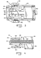
- Media feeder 12 illustrated in Fig. 1 is a horizontal feeder having a horizontal media tray 18, which may be integral with frame 16, or removable from frame members 16.
- a media stack 20 including a plurality of individual pieces of media 22 is placed in media tray 18, and individual pieces of media 22 are removed, one by one, from media stack 20 for use in downstream functions (not shown) of media processing device 14.
- Media tray 18 has a discharge end 24 at which separating device 10 of the present invention is positioned, to operate on individual pieces of media 22 to cause separation thereof from stack 20.
- Media tray 18 has a substantially horizontal, fixed position bottom 26.
- Media tray 18 also includes side positioning means (not shown) for media stack 20, as those skilled in the art will understand readily.
- Media feeder 12 further includes a feeding mechanism 28 including a feeding roll 30 that operates against the top piece of media 22 in media stack 20.
- Feeding roll 30 is directly or indirectly secured to one of the frame members 16, and is biased by a spring 32 against stack 20.
- Feeding roll 30 is rotatably driven by drive means (not shown) to rotate in the direction indicated by arrow 34 about an axis 36.
- Feeding roll 30 is provided with a peripheral surface 38 of rubber, plastic or other material to create sufficient friction between roll 30 and media 22 so that rotation of roll 30 drives the top piece of media 22 toward discharge end 24 of media tray 18.
- feeding mechanism 28 can be of other designs than that shown, which is only exemplary and not limiting of the present invention.
- the present invention can be used on media feeders of various types, including different feeding mechanisms.
- FIG. 1 A first embodiment of the present invention is shown in Figs. 1 and 2.
- Media separating device 10 includes a separator 50 mounted in media tray 18 at discharge end 24. Separator 50 is disposed at an outwardly reclining angle with respect to tray bottom 26, and has a surface 52 facing media stack 20.
- Surface 52 has an array of formations 54 thereon which engage media 22 to cause separation of individual pieces of media 22 from media stack 20. Formations 54 provide a series of surface segments of distinctly different slopes, and operate with segments of surface 52 between adjacent formations 54 to control bending or deflection of each piece of media 22 as it is driven thereagainst by feeding mechanism 28.
- FIG. 2 an enlarged portion of separator 50 is shown, with two formations 54 shown on a portion of surface 52 thereof. Formations 54 are spaced from each other along surface 52, with an exposed segment of surface 52 between adjacent formations 54. Formations 54 are generally triangular shaped bodies projecting from surface 52 toward media stack 20. Each formation 54 presents a substantially blunt or blocking surface 56 facing toward and confronting media stack 20. Blocking surface 56 inhibits or blocks forward moving pieces of media 22. Each formation 54 further includes a passing surface 58 positioned in a non-confronting orientation to advancing media 22. Passing surface 58 provides little or no hindrance to forward moving pieces of media 22. A curved apex 60 connects surfaces 56 and 58.
- Fig. 2 further illustrates some dimensional interrelationships for separator 50 that have been found to provide good performance with a range of standard types of media 22 commonly used.
- Arrowed line 62 represents the greatest dimension of formation 54 from surface 52, preferably between about 0.15mm and 0.75mm.
- Segmented arrowed line 64 represents the vertical height of formation 54 between the points at which surfaces 56 and 58 are connected to surface 52, which height is preferably between about 0.5mm and 15mm.
- Arrowed line 66 represents the vertical distance between the points at which adjacent formations 54 are connected to surface 52, such distance preferably being between about 0.1mm and 0.5mm.
- Segmented curved line 68 represents the angle between blocking surface 56 and a piece of media 22 passing over apex 60 and against the lowermost edge of blocking surface 56, the angle preferably being between about 60 degrees and 135 degrees.
- Opposed arrows 70 represent the thickness of media 22, and opposed arrows 72 represent the vertical distance between apex 60 of one formation 54 and the point at which blocking surface 56 is joined to surface 52. Preferably, the distance represented by opposed arrows 72 is greater than the distance represented by opposed arrows 70.
- Segmented curved line 74 designates the incline angle of surface 52 from the plane of tray bottom 26.
- Oppositely directed arrowed lines 76 designate the length of blocking surface 56.
- the preferred length of blocking surface 56 represented by arrowed lines 76 appears to be related to the incline angle of surface 52, represented by segmented curved line 74, although no direct mathematical relationship has been determined.
- the length of blocking surface 56 represented by arrowed lines 76 is longer for shallower angles of inclination represented by segmented curved line 74, and can be shorter for steeper angles of inclination represented by segmented curved line 74.
- feeding mechanism 28 is operatively engaged against the uppermost sheet of media 22 in media stack 20.
- Rotation of feeding roll 30 causes one or several sheets of media 22 to move toward discharge end 24 of tray 18.
- a leading edge of each advancing piece of media 22 abuts against surface 52 or blocking surface 56, causing upward deflection of leading edge.
- Continued advancement of media 22 causes leading edge to slide against segments of surface 52 between adjacent formations 54, and along blocking surfaces 56 of successive formations 54.
- An uppermost piece of media 22 eventually slides over apex 60 of one formation 54, with directs media 22 to slide rapidly over passing surface 58 of the same formation 54 to abut against surface 52 or a next formation 54 immediately thereabove.
- any piece of media 22 below the upper most media 22 is delayed slightly as the leading edge continues to engage blocking surface 56 of the lower formation 54.
- a shingling effect occurs between all adjacent pieces of media 22, with an uppermost piece of media 22 of each adjacent pair of media 22 advancing beyond the lower piece of the pair.
- Such shingling effect increases as pieces of media 22 advance from formation 54 to formation 54 along separator 50.
- the top piece of media 22 advances over an uppermost formation 54 of separator 20, and is grasped by media handling structures (not shown) outside of tray 18. At this point the top piece of media 22 has been separated sufficiently from any and all pieces of media 22 below it so that only the single uppermost piece of media 22 is removed from tray 18.
- FIG 1 illustrates somewhat schematically a spring means allowing separator 50 to yield slightly if sufficient force is applied thereagainst by advancing media 22.
- Separator 50 slides generally along a plane parallel to surface 52, which is along the angle of inclination of separator 50.
- FIG. 3 A preferred assembly 90 for a media-separating device in accordance with the present invention is illustrated in Fig. 3.
- Assembly 90 includes a separator component 92 and a holder 94 therefor.
- Separator component 92 can be provided as a monolithic structure of plastic or the like, and includes a separator 50 as described previously, including formations 54 thereon.
- Separator component 92 further includes lateral fins 96 and 98 at a lower end thereof, and arms 100 and 102 connected by shoulders 104 and 106, respectively, to separator 50. Shoulders 104 and 106 are connected to separator 50 at a center portion of separator 50, and extend outwardly from separator 50.
- Arms 100 and 102 extend from shoulders 104 and 106 toward an upper end of separator 50, substantially parallel to but spaced from separator 50. Arms 100, 102 and shoulders 104, 106 can deflect from force applied against the distal ends of arms 100 and 102. Tips 108 and 110 of arms 100 and 102, respectively, preferably are provided in curved (Fig. 3) or angled (Fig. 4) formations.
- Holder 94 is a somewhat box-like structure for holding and directing movement of separator component 92.
- Holder 94 has a panel 112 and sides 114 and 116 between which separator component 92 can slide.
- Panel 112 defines a slot 118 through which separator 50 projects. Slot 118 is longer than separator 50, allowing axial movement of separator 50 along and within slot 118.
- a stop 120 is provided on panel 112, near a lower end of slot 118.
- Angular blocks 122 and 124 are provided on panel 112 at an upper end thereof, just outwardly from slot 118.
- Fig. 7 illustrates a passive media-separating device 134 of the present invention operating on a vertical media feeder 136 of a media-processing device 138.
- the embodiment illustrated in Fig. 7 is similar to that described previously herein, except that media feeder 136 illustrated in Fig. 7 is a vertical feeder having a substantially vertically oriented media stack 140 positioned against a substantially vertical support 142.
- a bottom 144 supports edges of some or all individual pieces of media 146 in stack 140. Individual pieces of media 146 are removed, one by one, from media stack 140 for use in downstream functions of media processing device 138.
- Media feeder 136 has a discharge side 148, and separating device 134 of the present invention is positioned along a bottom of media stack 140, between discharge side 148 and bottom 144.
- media stack 140 can be positioned against a first length of separating device 134 indicated by line 150. As can be seen from Fig. 7, initial shingling of individual pieces of media 146 occurs along the first length of separating device 134 from the positioning of any portion of media stack 140 thereagainst.
- Media feeder 136 further includes a feeding mechanism 152 including a feeding roll 154 that operates against media stack 140.
- Feeding roll 154 is biased by a spring 156 against stack 140.
- Feeding roll 154 is rotatably driven by drive means (not shown) to rotate in the direction indicated by arrow 158 about an axis 160.
- Feeding roll 154 is provided with a peripheral surface 162 of rubber, plastic or other material to creating sufficient friction between roll 154 and media 146 so that rotation of roll 154, together with the force of gravity, drives the outermost piece of media 146 toward discharge side 148.
- Separating device 134 includes a separator 164 having a surface 166 facing media stack 140.
- Surface 166 has an array of formations 168 extending therealong to discharge side 148. Separating device 134 operates similarly to separating device 10, to cause progressively increasing shingling of media 146 being moved toward discharge side 148 by feeding mechanism 152.
- a modified separator 170 (Fig. 8) formations 54 as described previously, are provided along an upper portion of separator 170, and along a lower portion thereof, designated by arrowed line 172, modified formations 174 are provided.
- Each formation 174 has a truncated apex 176, the truncations of which increase from the last of formations 54 toward the lower end of separator 170.
- Progressively increasing truncated apexes 176 promote removal and separation of media 22 at the lower end of media stack 20, where the force of engagement between feeding roll 30 and the uppermost piece of media 22 has lessened.
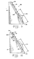
- a media separating device 180 is provided with a pivotally mounted separator 182 having a surface 52 and projections 54 and 174 similar to those described previously herein. Separator 182 is connected to frame member 16 only by an axis 184 about which separator 182 can pivot Spring means (not shown) can be provided along and associated with pivotal movement about axis 184, or between separator 182 and frame member 16.
- a media separating device 190 is provided with a cantilevered separator 192 having a surface 52 and projections 54 and 174 similar to those described previously herein.
- Cantilevered separator 192 is connected to frame 16 at a lower end 194 of separator 192, but is otherwise unattached, defining a space 196 between frame 16 and separator 192.
- Springing deflection of separator 192 occurs at lower end 194.
- Further assistance can be provided with a spring 198 near distal end 200 of separator 192, to provide more robust resistance to deflection of cantilevered separator 192.
- Springs 198 of different spring force can be used, depending upon the types of media to be separated by separating device 190.
- the present invention provides a media-separating device that works effectively for different types of media from the top piece of media in a media stack to the bottom piece of media in the stack.
- the device is mechanically simple, and can be provided inexpensively, for a variety of different feed mechanisms and media feeders.
- the blunt blocking surfaces of the separators provide abutments against which a stack of media can be placed, and thereby prevent heretofore experienced disadvantages of other separators in such conditions.
Abstract
Description
- This application claims benefit of United States Provisional Application No. 60/403,931, filed August 16, 2002.
- The present invention relates to media handling devices such as printers, copiers, fax machines and the like, and, more particularly, the present invention relates to media separating devices used in the feed mechanisms for such machines.
- Printers, copiers, fax machines, scanners and the like use a variety of different pick mechanisms to deliver individual sheets of media to a delivery or indexing system. It is known to provide a stack of media in a tray, which may be vertical, horizontal or at some angle therebetween, and to feed individual sheets from the stack to the device. For trouble free operation of the device, it is necessary that only a single sheet be fed at a time. Thus, the pick mechanism and sheet feed structure must include some means for individualizing or separating a single sheet from the stack of sheets. In very high-speed devices that are often costly, it is known to use sheet feeders having relatively complex mechanical mechanisms for separating the individual sheets. However, there is a need also for lower cost printers, copiers, fax machines and the like. These machines must also separate and feed media reliably, but with less expensive and less complicated mechanisms. Therefore, simple, reliable, inexpensive sheet separating devices are required.
- Passive separation devices are known to have a slanted rubber element against which an advancing piece of media is driven. The media is driven from the top of a stack of media by a spring-biased feeding wheel. Separation occurs from the friction of the advancing media edge against the rubber surface. The angle of the rubber surface in relation to the advancing media and the frictional coefficient of the rubber impact the performance of such devices. If the media stack is large, the stack covers much of the rubber surface, and the exposed distance over which separation can occur is small. Further, the feed wheel rides on top of the media stack, biased thereagainst by a spring. When the media stack is tall, the spring force exerted against the stack through the drive wheel is large and friction between sheets is high. Coupled with the short separation distance available, these conditions can lead to double feeding. Conversely, when the media stack is short, the spring force against the stack is lower, and may be inadequate to empty the media tray if the spring is adjusted to eliminate potential double feeding from a tall media stack. Further problems are experienced if the stack of media is positioned too closely to the rubber surface. Double feeding and jamming can result if the stack of media is forced against the rubber surface.
- Designing a simple but effective separating device is complicated by several factors. As mentioned previously, sheet feed devices can be horizontal, vertical or at some angle between horizontal and vertical. Further, it is common and desirable for the devices such as printers, copiers and fax machines to process a variety of different materials. For example, a printer may routinely handle relatively lightweight, draft grade papers, heavier weight bond papers, card stock, transparencies and envelopes. To simplify the device and reduce cost, while also reducing the chance for mechanical failure, it is desirable that many functions of the machine be relatively passive, that is, the function performed with minimal mechanical movement or operation.
- While known separating devices have functioned satisfactorily to some extent, as speeds increase more definite reliable separation is required. Further, it is desirable that the separating device function consistently with different types of media, from the top piece of media in a stack to the bottom piece of media in the stack.
- The present invention provides a passive media-separating device having a formed surface to separate and maintain separation between individual media fed from a stack of media.
- In one form thereof, the present invention provides a media-separating device for a media feeder in a media-processing device wherein individual pieces of media are picked from a stack of media and advanced for individual handing in the media-processing device. The separating device has a separator with a surface thereof disposed in a substantially confronting position relative to the stack of media, to confront the leading edges of pieces of media removed the stack. An array of formations is provided on the surface of the separator. Each formation includes a blocking surface positioned for confronting the leading edges of the moving media, a passing surface in a substantially non-confronting position relative to the leading edges of the media, and an apex at a connection between the blocking and passing surfaces. The apex is positioned relative to the passing surface and the movement of the leading edges for directing the leading edges over the passing surface. The array provides a succession of the formations along a path of travel by the leading edges of media removed from the stack. Means are provided for driving pieces of media from the stack against the separator.
- in another form thereof, the present invention provides a media feeder for a media processing device with a media tray for holding a stack of media, a feeding mechanism for moving a first piece of media from the stack toward a discharge point and a media separating device. The media separating device includes a surface facing leading edges of media in a stack of media held in the tray. The surface includes a series of surface formations. Each formation includes a blocking surface positioned for confronting the leading edges of the moving media, a passing surface in a substantially non-confronting position relative to the leading edges of the media and an apex at a connection between the blocking and passing surfaces. The apex is positioned relative to the passing surface and the movement of the leading edges for directing the leading edges over the passing surface.
- In still another form thereof, the present invention provides a media separating device assembly for a media feeder. The assembly has a separator holder including a panel defining a slot; sides on opposite edges of the panel and blocks on a surface of the panel. The blocks are disposed on opposite sides of the slot near one end of the slot. Each block has an angular surface angling from one of the sides inwardly toward the slot and outwardly toward the one end. A separator component is slidable relative to the panel between the sides. The separator component includes an elongated separator have an array of formations thereon. The separator is positioned in the slot with the formations projecting beyond an opposite surface of the panel. Arms connected to the separator extend along and spaced from the separator. Tips of the arms engage the angular surfaces of the blocks.
- An advantage of the present invention is providing a passive media-separating device that is simple, inexpensive, easily installed, and consistent in performance.
- Another advantage of the present invention is providing a media-separating device that works effectively on a wide range of media types, including heavier and lighter weight media.
- A further advantage of the present invention is providing a media-separating device that provides a barricade against improper loading of a paper tray.
- Yet another advantage of the present invention is providing a media-separating device that works effectively on all pieces of media in a stack, from the top pieces in a full media tray to the bottom pieces in the media tray.
- Still another advantage of the present invention is providing a media-separating device that works effectively on a variety of media feeders, including both horizontal feeders and vertical feeders.
- Other features and advantages of the invention will become apparent to those skilled in the art upon review of the following detailed description, claims and drawings in which like numerals are used to designate like features.
-
- Fig. 1 is an elevational view of a horizontal media feeder having a passive media separating device in accordance with the present invention;
- Fig. 2 is an enlarged view of a portion of a media separator in the separating device of the present invention;
- Fig. 3 is a plan view of a preferred assembly for a media separating device of the present invention, including a media separator and a holder therefor;
- Fig. 4 is a perspective view of the media separator in the media separating device shown in Fig. 3;
- Fig. 5 is a perspective view of the holder for the media separator shown in Fig. 3;
- Fig. 6 is a cross-sectional view showing the holder attached to a component of a media feeder;
- Fig. 7 is an elevational view of a passive media separating device in accordance with the present invention, shown for operation in a vertical media feeder;
- Fig. 8 is a side elevational view of the present passive media separating device, illustrating a modified form of the invention;
- Fig. 9 is a side view similar to Fig. 8, but illustrating a further modification of the present invention; and
- Fig. 10 is a side view similar to Fig. 8 and 9, but illustrating still further modifications of the present invention.
-
- Before the embodiments of the invention are explained in detail, it is to be understood that the invention is not limited in its application to the details of construction and the arrangements of the components set forth in the following description or illustrated in the drawings. The invention is capable of other embodiments and of being practiced or being carried out in various ways. Also, it is understood that the phraseology and terminology used herein are for the purpose of description and should not be regarded as limiting. The use herein of "including" and "comprising" and variations thereof is meant to encompass the items listed thereafter and equivalents thereof, as well as additional items and equivalents thereof.
- Referring now more specifically to the drawings and to Fig. 1 in particular, a passive
media separating device 10 in accordance with the present invention is shown in amedia feeder 12 of a media-processingdevice 14 includingframe members 16.Media processing device 14 can be a printer, copier, fax machine, scanner or other machine in which media is processed individually in some manner. In that regard,media feeder 12 can be provided for feeding clean pieces of media such as paper of various weights, envelopes, card stock, transparencies, or the like for receiving printing thereon in a printer, fax machine, copier, etc. Alternatively,media feeder 12 can be provided for feeding original documents to be scanned, copied, faxed or the like.Media separating device 10 works well for many applications in which media of some type is removed from a media stack and fed individually for further processing. -
Media feeder 12 illustrated in Fig. 1 is a horizontal feeder having ahorizontal media tray 18, which may be integral withframe 16, or removable fromframe members 16. A media stack 20 including a plurality of individual pieces ofmedia 22 is placed inmedia tray 18, and individual pieces ofmedia 22 are removed, one by one, from media stack 20 for use in downstream functions (not shown) ofmedia processing device 14. -
Media tray 18 has adischarge end 24 at which separatingdevice 10 of the present invention is positioned, to operate on individual pieces ofmedia 22 to cause separation thereof fromstack 20.Media tray 18 has a substantially horizontal, fixed position bottom 26.Media tray 18 also includes side positioning means (not shown) formedia stack 20, as those skilled in the art will understand readily. -
Media feeder 12 further includes afeeding mechanism 28 including a feedingroll 30 that operates against the top piece ofmedia 22 inmedia stack 20. Feedingroll 30 is directly or indirectly secured to one of theframe members 16, and is biased by aspring 32 againststack 20. Feedingroll 30 is rotatably driven by drive means (not shown) to rotate in the direction indicated byarrow 34 about anaxis 36. Feedingroll 30 is provided with aperipheral surface 38 of rubber, plastic or other material to create sufficient friction betweenroll 30 andmedia 22 so that rotation ofroll 30 drives the top piece ofmedia 22 toward discharge end 24 ofmedia tray 18. Those skilled in the art will understand that feedingmechanism 28 can be of other designs than that shown, which is only exemplary and not limiting of the present invention. The present invention can be used on media feeders of various types, including different feeding mechanisms. - A first embodiment of the present invention is shown in Figs. 1 and 2.
Media separating device 10 includes aseparator 50 mounted inmedia tray 18 atdischarge end 24.Separator 50 is disposed at an outwardly reclining angle with respect to tray bottom 26, and has asurface 52 facingmedia stack 20.Surface 52 has an array offormations 54 thereon which engagemedia 22 to cause separation of individual pieces ofmedia 22 frommedia stack 20.Formations 54 provide a series of surface segments of distinctly different slopes, and operate with segments ofsurface 52 betweenadjacent formations 54 to control bending or deflection of each piece ofmedia 22 as it is driven thereagainst by feedingmechanism 28. - With reference now to Fig. 2, an enlarged portion of
separator 50 is shown, with twoformations 54 shown on a portion ofsurface 52 thereof.Formations 54 are spaced from each other alongsurface 52, with an exposed segment ofsurface 52 betweenadjacent formations 54.Formations 54 are generally triangular shaped bodies projecting fromsurface 52 towardmedia stack 20. Eachformation 54 presents a substantially blunt or blockingsurface 56 facing toward and confrontingmedia stack 20. Blockingsurface 56 inhibits or blocks forward moving pieces ofmedia 22. Eachformation 54 further includes a passingsurface 58 positioned in a non-confronting orientation to advancingmedia 22. Passingsurface 58 provides little or no hindrance to forward moving pieces ofmedia 22. Acurved apex 60 connectssurfaces - Fig. 2 further illustrates some dimensional interrelationships for
separator 50 that have been found to provide good performance with a range of standard types ofmedia 22 commonly used.Arrowed line 62 represents the greatest dimension offormation 54 fromsurface 52, preferably between about 0.15mm and 0.75mm. Segmented arrowedline 64 represents the vertical height offormation 54 between the points at which surfaces 56 and 58 are connected to surface 52, which height is preferably between about 0.5mm and 15mm.Arrowed line 66 represents the vertical distance between the points at whichadjacent formations 54 are connected to surface 52, such distance preferably being between about 0.1mm and 0.5mm. Segmentedcurved line 68 represents the angle between blockingsurface 56 and a piece ofmedia 22 passing overapex 60 and against the lowermost edge of blockingsurface 56, the angle preferably being between about 60 degrees and 135 degrees.Opposed arrows 70 represent the thickness ofmedia 22, and opposedarrows 72 represent the vertical distance betweenapex 60 of oneformation 54 and the point at which blockingsurface 56 is joined to surface 52. Preferably, the distance represented byopposed arrows 72 is greater than the distance represented byopposed arrows 70. Segmentedcurved line 74 designates the incline angle ofsurface 52 from the plane of tray bottom 26. Oppositely directed arrowedlines 76 designate the length of blockingsurface 56. Through testing, the preferred length of blockingsurface 56 represented byarrowed lines 76 appears to be related to the incline angle ofsurface 52, represented by segmentedcurved line 74, although no direct mathematical relationship has been determined. Generally, the length of blockingsurface 56 represented byarrowed lines 76 is longer for shallower angles of inclination represented by segmentedcurved line 74, and can be shorter for steeper angles of inclination represented by segmentedcurved line 74. - In the use of
media feeder 12 havingmedia separating device 10,feeding mechanism 28 is operatively engaged against the uppermost sheet ofmedia 22 inmedia stack 20. Rotation of feedingroll 30 causes one or several sheets ofmedia 22 to move toward discharge end 24 oftray 18. A leading edge of each advancing piece ofmedia 22 abuts againstsurface 52 or blockingsurface 56, causing upward deflection of leading edge. Continued advancement ofmedia 22 causes leading edge to slide against segments ofsurface 52 betweenadjacent formations 54, and along blockingsurfaces 56 ofsuccessive formations 54. An uppermost piece ofmedia 22 eventually slides overapex 60 of oneformation 54, with directsmedia 22 to slide rapidly over passingsurface 58 of thesame formation 54 to abut againstsurface 52 or anext formation 54 immediately thereabove. At the same time, any piece ofmedia 22 below the uppermost media 22 is delayed slightly as the leading edge continues to engage blockingsurface 56 of thelower formation 54. A shingling effect occurs between all adjacent pieces ofmedia 22, with an uppermost piece ofmedia 22 of each adjacent pair ofmedia 22 advancing beyond the lower piece of the pair. Such shingling effect increases as pieces ofmedia 22 advance fromformation 54 toformation 54 alongseparator 50. Eventually, the top piece ofmedia 22 advances over anuppermost formation 54 ofseparator 20, and is grasped by media handling structures (not shown) outside oftray 18. At this point the top piece ofmedia 22 has been separated sufficiently from any and all pieces ofmedia 22 below it so that only the single uppermost piece ofmedia 22 is removed fromtray 18. - When heavyweight papers, card stock or other
rigid media 22 is used, performance ofseparator 50 is improved ifseparator 50 is allowed to move slightly when engaged by leading edges 78 of the morerigid media 22. Fig 1 illustrates somewhat schematically a spring means allowingseparator 50 to yield slightly if sufficient force is applied thereagainst by advancingmedia 22.Separator 50 slides generally along a plane parallel to surface 52, which is along the angle of inclination ofseparator 50. - A
preferred assembly 90 for a media-separating device in accordance with the present invention is illustrated in Fig. 3.Assembly 90 includes aseparator component 92 and aholder 94 therefor.Separator component 92, best seen in Fig. 4, can be provided as a monolithic structure of plastic or the like, and includes aseparator 50 as described previously, includingformations 54 thereon.Separator component 92 further includeslateral fins arms shoulders separator 50.Shoulders separator 50, and extend outwardly fromseparator 50.Arms shoulders separator 50, substantially parallel to but spaced fromseparator 50.Arms shoulders arms Tips arms -
Holder 94, seen best in Fig. 5, is a somewhat box-like structure for holding and directing movement ofseparator component 92.Holder 94 has apanel 112 andsides separator component 92 can slide.Panel 112 defines aslot 118 through which separator 50 projects.Slot 118 is longer thanseparator 50, allowing axial movement ofseparator 50 along and withinslot 118. Astop 120 is provided onpanel 112, near a lower end ofslot 118.Angular blocks panel 112 at an upper end thereof, just outwardly fromslot 118.Surfaces blocks sides slot 118.Hooks sides holder 94 to a frame member 16 (Fig. 6), or to a portion oftray 18 atdischarge end 24.Holder 94 is thus attached withseparator component 92 held betweenpanel 112 andframe member 16, andseparator 50 projecting throughslot 118. - In using
assembly 90, force ofrigid media 22 againstseparator 50 can causeseparator component 92 to slide upwardly withinholder 94.Fins arms panel 112 outwardly ofslot 118, withseparator 50 confined withinslot 118. As separator component moves upwardly inholder 94,tips arms surfaces blocks surfaces causes arms separator component 92 moves further fromstop 120. The spring like affect resulting therefrom provides resistance to sliding byseparator component 92, and returnsseparator component 92 to a lowest position againststop 120 when force againstseparator 50 is diminished or eliminated. - Fig. 7 illustrates a passive media-separating
device 134 of the present invention operating on avertical media feeder 136 of a media-processing device 138. The embodiment illustrated in Fig. 7 is similar to that described previously herein, except thatmedia feeder 136 illustrated in Fig. 7 is a vertical feeder having a substantially vertically orientedmedia stack 140 positioned against a substantiallyvertical support 142. A bottom 144 supports edges of some or all individual pieces ofmedia 146 instack 140. Individual pieces ofmedia 146 are removed, one by one, from media stack 140 for use in downstream functions ofmedia processing device 138.Media feeder 136 has adischarge side 148, and separatingdevice 134 of the present invention is positioned along a bottom ofmedia stack 140, betweendischarge side 148 andbottom 144. Some or all of media stack 140 can be positioned against a first length of separatingdevice 134 indicated byline 150. As can be seen from Fig. 7, initial shingling of individual pieces ofmedia 146 occurs along the first length of separatingdevice 134 from the positioning of any portion of media stack 140 thereagainst. -
Media feeder 136 further includes afeeding mechanism 152 including afeeding roll 154 that operates againstmedia stack 140. Feedingroll 154 is biased by aspring 156 againststack 140. Feedingroll 154 is rotatably driven by drive means (not shown) to rotate in the direction indicated byarrow 158 about anaxis 160. Feedingroll 154 is provided with aperipheral surface 162 of rubber, plastic or other material to creating sufficient friction betweenroll 154 andmedia 146 so that rotation ofroll 154, together with the force of gravity, drives the outermost piece ofmedia 146 towarddischarge side 148. - Separating
device 134 includes aseparator 164 having asurface 166 facingmedia stack 140.Surface 166 has an array offormations 168 extending therealong to dischargeside 148. Separatingdevice 134 operates similarly to separatingdevice 10, to cause progressively increasing shingling ofmedia 146 being moved towarddischarge side 148 by feedingmechanism 152. - In a modified separator 170 (Fig. 8),
formations 54 as described previously, are provided along an upper portion ofseparator 170, and along a lower portion thereof, designated byarrowed line 172, modifiedformations 174 are provided. Eachformation 174 has atruncated apex 176, the truncations of which increase from the last offormations 54 toward the lower end ofseparator 170. Progressively increasingtruncated apexes 176 promote removal and separation ofmedia 22 at the lower end ofmedia stack 20, where the force of engagement between feedingroll 30 and the uppermost piece ofmedia 22 has lessened. - In another variation of the present invention (Fig. 9), a
media separating device 180 is provided with a pivotally mountedseparator 182 having asurface 52 andprojections Separator 182 is connected to framemember 16 only by anaxis 184 about which separator 182 can pivot Spring means (not shown) can be provided along and associated with pivotal movement aboutaxis 184, or betweenseparator 182 andframe member 16. - In a further variation for providing springing resistance in the present invention (Fig. 10), a media separating device 190 is provided with a cantilevered
separator 192 having asurface 52 andprojections Cantilevered separator 192 is connected to frame 16 at alower end 194 ofseparator 192, but is otherwise unattached, defining aspace 196 betweenframe 16 andseparator 192. Springing deflection ofseparator 192 occurs atlower end 194. Further assistance can be provided with aspring 198 neardistal end 200 ofseparator 192, to provide more robust resistance to deflection ofcantilevered separator 192.Springs 198 of different spring force can be used, depending upon the types of media to be separated by separating device 190. - The present invention provides a media-separating device that works effectively for different types of media from the top piece of media in a media stack to the bottom piece of media in the stack. The device is mechanically simple, and can be provided inexpensively, for a variety of different feed mechanisms and media feeders. The blunt blocking surfaces of the separators provide abutments against which a stack of media can be placed, and thereby prevent heretofore experienced disadvantages of other separators in such conditions.
- Variations and modifications of the foregoing are within the scope of the present invention. It is understood that the invention disclosed and defined herein extends to all alternative combinations of two or more of the individual features mentioned or evident from the text and/or drawings. All of these different combinations constitute various alternative aspects of the present invention. The embodiments described herein explain the best modes known for practicing the invention and will enable others skilled in the art to utilize the invention. The claims are to be construed to include alternative embodiments to the extent permitted by the prior art
- Various features of the invention are set forth in the following claims.
Claims (26)
- A media separating device for a media feeder in a media processing device wherein individual pieces of media are picked from a stack of media and advanced for individual handing in the media processing device, said separating device comprising:a separator having a surface thereof disposed in a substantially confronting position relative to the stack of media to confront the leading edges of pieces of media removed the stack;an array of formations on said surface of said separator; each formation including;a blocking surface positioned for confronting the leading edges of the moving media, causing the leading edges to deflect when abutted against said blocking surface;a passing surface in a substantially non-confronting position relative to the leading edges of the media over which the media will slide; andan apex at a connection between said blocking and passing surfaces, said apex positioned relative to said passing surface and the movement of said leading edges for directing the leading edges over the passing surface; andsaid array providing a succession of said formations along a path of travel by the leading edges of media removed from the stack; andmeans for driving pieces of media from the stack against the separator.
- The media separating device of claim 1, said formations arranged in spaced relation along a length of said separator, exposing a segment of said separator surface between adjacent ones of said formations.
- The media separating device of claim 1 or 2, said separator disposed at an angle of inclination upwardly and away from a base of the stack of media.
- The media separating device of claim 3, said separator being movable along said angle of inclination, and being biased toward said base of the stack of media.
- The media separating device of claim 3 or 4, said separator being cantilevered from said base of the stack of media.
- The media separating device of at least one of the preceding claims said separator having an upper end and a lower end and being pivotable about an axis between said upper and lower ends.
- The media separating device of at least one of claims 3 to 6 said separator being cantilevered from said base of the stack of media, and said device including a spring exerting force against said separator.
- The media separating device of at least one of the preceding claims, said formations including a first group of formations near said base having a first shape and a second group of formations near a distal end of said separator having a second shape different from said shape of said first group.
- The media separating device of claim 8, said group of formations near said base having truncated apexes.
- The media separating device of at least one of the preceding claims said formations including a first group of formations first confronted by said leading edges and a second group of formations confronted thereafter, said formations of said first group having shapes different from a shape of formations of said second group.
- The media separating device of claim 10, said first group of formations having truncated apexes.
- The media separating device of at least one of the preceding claims, including a holder secured in said media feeder, and said separator being movably held by said holder.
- The media separating device of claim 12, said holder defining a slot, and said formations projecting through said slot.
- The media separating device of at least one of the preceding claims, said separator having shoulders extending outwardly from opposite sides thereof, and arms connected to said shoulders extending along and spaced from said separator.
- The media separating device of claim 14, said holder having blocks with angled surfaces thereon, and said arms having tips abutting and sliding along said angled surfaces for deflecting said arms.
- A media feeder for a media processing device, comprising:a media tray for holding a stack of media, said media tray having a discharge point;a feeding mechanism for moving a first piece of media from the stack toward the discharge point; anda media separating device including a surface facing leading edges of media in a stack of media held in the tray, said surface including a series of surface formations, each formation including;a blocking surface positioned for confronting the leading edges of the moving media, causing the leading edges to deflect when abutted against said blocking surface;a passing surface in a substantially non-confronting position relative to the leading edges of the media over which the media will slide; andan apex at a connection between said blocking and passing surfaces, said apex positioned relative to said passing surface and the movement of said leading edges for directing the leading edges over the passing surface.
- The media feeder of claim 16, said media separating device comprising an elongated separator disposed angularly, upwardly and outwardly from a bottom of the tray.
- The media feeder of claim 17, said separator being spring biased toward said bottom.
- The media feeder of claim 17 or 18, said separator having an upper end and a lower end and defining a pivot between said upper end and said lower end; and said separator being pivotable about said pivot.
- The media feeder of at least one of claims 17 to 19, said separator beingfixed at said lower end and being cantilevered from said lower end.
- The media feeder of at least one of claims 16 to 20, said surface formations including a first group of formations near a bottom of said tray and a second group of formations, said formations of said second group each having a shape different from shapes of said formations in said first group.
- The media feeder of claim 21, said formations of said first group having truncated apexes.
- A media separating device assembly for a media feeder, said assembly comprising:a separator holder including:a panel defining a slot;sides on opposite edges of said panel, said sides defining a path therebetween; andblocks on a surface of said panel, said blocks disposed on opposite sides of said slot near one end of said slot, each said block having an angular surface angling from one of said sides inwardly toward said slot and outwardly toward said one end; anda separator component slidable relative to said panel between said sides, said separator component including:an elongated separator having an array of formations thereon, said separator positioned in said slot with said formations projecting beyond an opposite surface of said panel;arms connected to said separator and extending along and spaced from said separator; andtips of said arms engaging said angular surfaces of said blocks.
- The media separating device assembly of claim 23, said holder including a stop on said panel at an end of said slot opposite said one end of said slot.
- The media separating device assembly of claim 23 or 24, said separator component including fins connected to said separator, said fins adapted for sliding on said panel.
- The media separating device assembly of at least one of claims 23 to 25, said separator holder including hooks for attach said holder to said media feeder.
Applications Claiming Priority (4)
| Application Number | Priority Date | Filing Date | Title |
|---|---|---|---|
| US40393102P | 2002-08-16 | 2002-08-16 | |
| US403931P | 2002-08-16 | ||
| US454180 | 2003-06-04 | ||
| US10/454,180 US7036814B2 (en) | 2002-08-16 | 2003-06-04 | Passive media separating device |
Publications (2)
| Publication Number | Publication Date |
|---|---|
| EP1389599A2 true EP1389599A2 (en) | 2004-02-18 |
| EP1389599A3 EP1389599A3 (en) | 2004-12-08 |
Family
ID=30773143
Family Applications (1)
| Application Number | Title | Priority Date | Filing Date |
|---|---|---|---|
| EP03016941A Withdrawn EP1389599A3 (en) | 2002-08-16 | 2003-07-25 | Passive media separating device |
Country Status (3)
| Country | Link |
|---|---|
| US (1) | US7036814B2 (en) |
| EP (1) | EP1389599A3 (en) |
| JP (1) | JP4053952B2 (en) |
Cited By (3)
| Publication number | Priority date | Publication date | Assignee | Title |
|---|---|---|---|---|
| EP1580154A1 (en) * | 2004-03-05 | 2005-09-28 | Brother Kogyo Kabushiki Kaisha | Sheet separation member and sheet supply device |
| CN101844686A (en) * | 2009-03-26 | 2010-09-29 | 兄弟工业株式会社 | Paper separating device, sheet feed stacker and paper feed with this device |
| CN102134012A (en) * | 2010-01-25 | 2011-07-27 | 精工爱普生株式会社 | Sheet material feeding and recording apparatus |
Families Citing this family (30)
| Publication number | Priority date | Publication date | Assignee | Title |
|---|---|---|---|---|
| US7193834B2 (en) * | 2003-01-17 | 2007-03-20 | Illinois Tool Works Inc | Static charge-immune enclosure |
| US6969168B2 (en) * | 2003-09-19 | 2005-11-29 | Hewlett-Packard Development Company, L.P. | Media loading and separation system for printer |
| US20050242491A1 (en) * | 2004-04-30 | 2005-11-03 | Fujifilm Electronic Imaging Ltd. | Plate feeding apparatus |
| US7407158B2 (en) * | 2004-05-14 | 2008-08-05 | Seiko Epson Corporation | Sheet feeding device with variable faced roller and integrated sheet guides |
| JP4415792B2 (en) | 2004-08-24 | 2010-02-17 | ブラザー工業株式会社 | Image recording device |
| JP4284542B2 (en) * | 2005-01-26 | 2009-06-24 | ブラザー工業株式会社 | Paper feeder |
| TWI256343B (en) * | 2005-07-01 | 2006-06-11 | Benq Corp | Paper feeding apparatus and sheet separating device thereof |
| JP4224718B2 (en) * | 2005-09-29 | 2009-02-18 | ブラザー工業株式会社 | Paper feeder |
| US7513495B2 (en) * | 2005-12-13 | 2009-04-07 | Hewlett-Packard Development Company, L.P. | Separator |
| US20070182086A1 (en) * | 2006-02-09 | 2007-08-09 | Lexmark International, Inc. | Methods and devices for controlling a leading edge of a media sheet in an image forming device |
| US7852526B2 (en) * | 2006-04-28 | 2010-12-14 | Hewlett-Packard Development Company, L.P. | Separator |
| US7988143B2 (en) * | 2007-03-23 | 2011-08-02 | Brother Kogyo Kabushiki Kaisha | Sheet feeder |
| JP4650640B2 (en) * | 2007-03-26 | 2011-03-16 | ブラザー工業株式会社 | Paper feeder |
| US20080237976A1 (en) * | 2007-03-27 | 2008-10-02 | Niko Jay Murrell | Media Sheet Ramp For An Image Forming Device |
| US20090026693A1 (en) * | 2007-07-26 | 2009-01-29 | Boo Siong Sean Lim | Sheet Separating Mechanism And Sheet Feeding Apparatus Having The Same |
| JP4582358B2 (en) * | 2008-03-31 | 2010-11-17 | ブラザー工業株式会社 | Paper feeding device and image recording apparatus having the same |
| US8378548B2 (en) * | 2009-09-17 | 2013-02-19 | Illinois Tool Works Inc. | Current control assembly with drainage and slinger |
| JP5321394B2 (en) * | 2009-09-30 | 2013-10-23 | ブラザー工業株式会社 | Sheet conveying apparatus and image recording apparatus |
| JP5484017B2 (en) * | 2009-11-27 | 2014-05-07 | キヤノン株式会社 | Paper feeding device and image forming apparatus having the same |
| US8328183B2 (en) | 2010-08-30 | 2012-12-11 | Eastman Kodak Company | Media stopper for a printing system |
| US8215631B2 (en) | 2010-08-30 | 2012-07-10 | Eastman Kodak Company | Pick roller retraction in a carriage printer |
| US8215633B2 (en) | 2010-08-30 | 2012-07-10 | Eastman Kodak Company | Media stopper method for a printing system |
| US20120050437A1 (en) * | 2010-08-30 | 2012-03-01 | Stiehler Wayne E | Media separator for a printing system |
| US8215632B2 (en) | 2010-08-30 | 2012-07-10 | Eastman Kodak Company | Pick roller retraction method in a carriage printer |
| US20130020754A1 (en) * | 2011-07-22 | 2013-01-24 | John Anthony Schmidt | Slidable Sheet Separator for an Image Forming Device |
| US8256761B1 (en) * | 2011-07-22 | 2012-09-04 | Lexmark International, Inc. | Sheet separator having multi axis motion for an image forming device |
| JP5854696B2 (en) | 2011-08-18 | 2016-02-09 | キヤノン株式会社 | Paper feeding device and recording device |
| JP5899708B2 (en) * | 2011-08-29 | 2016-04-06 | セイコーエプソン株式会社 | Medium feeding device, recording device |
| US9573779B2 (en) * | 2014-02-19 | 2017-02-21 | Canon Kabushiki Kaisha | Feeding apparatus and printing apparatus |
| JP7088267B2 (en) * | 2020-11-24 | 2022-06-21 | ブラザー工業株式会社 | Feeding device and image recording device |
Citations (8)
| Publication number | Priority date | Publication date | Assignee | Title |
|---|---|---|---|---|
| US4541623A (en) * | 1982-12-27 | 1985-09-17 | International Business Machines Corporation | Alignment restraint station |
| US5660384A (en) * | 1994-11-23 | 1997-08-26 | Minnesota Mining And Manufacturing Company | Imaging unit container having shiftable walls |
| US6139007A (en) * | 1999-10-22 | 2000-10-31 | Lexmark International, Inc. | Sheet separator dam with buckling element |
| EP1125873A1 (en) * | 1997-06-20 | 2001-08-22 | Lexmark International, Inc. | Sheet separator |
| US20010040335A1 (en) * | 2000-05-12 | 2001-11-15 | Won-Kil Chang | Sheet separator in a printer |
| US20020008348A1 (en) * | 2000-03-13 | 2002-01-24 | Ryukichi Inoue | Sheet feeding apparatus and image forming apparatus having same |
| TW483833B (en) * | 2001-05-03 | 2002-04-21 | Benq Corp | Paper feeding mechanism |
| US20020060396A1 (en) * | 2000-09-01 | 2002-05-23 | Hironori Tanaka | Paper sheet feeding apparatus |
Family Cites Families (1)
| Publication number | Priority date | Publication date | Assignee | Title |
|---|---|---|---|---|
| US5560597A (en) * | 1994-11-23 | 1996-10-01 | Harris Corporation | Imaging unit container including bag clamping member |
-
2003
- 2003-06-04 US US10/454,180 patent/US7036814B2/en not_active Expired - Fee Related
- 2003-07-25 EP EP03016941A patent/EP1389599A3/en not_active Withdrawn
- 2003-08-18 JP JP2003294421A patent/JP4053952B2/en not_active Expired - Fee Related
Patent Citations (8)
| Publication number | Priority date | Publication date | Assignee | Title |
|---|---|---|---|---|
| US4541623A (en) * | 1982-12-27 | 1985-09-17 | International Business Machines Corporation | Alignment restraint station |
| US5660384A (en) * | 1994-11-23 | 1997-08-26 | Minnesota Mining And Manufacturing Company | Imaging unit container having shiftable walls |
| EP1125873A1 (en) * | 1997-06-20 | 2001-08-22 | Lexmark International, Inc. | Sheet separator |
| US6139007A (en) * | 1999-10-22 | 2000-10-31 | Lexmark International, Inc. | Sheet separator dam with buckling element |
| US20020008348A1 (en) * | 2000-03-13 | 2002-01-24 | Ryukichi Inoue | Sheet feeding apparatus and image forming apparatus having same |
| US20010040335A1 (en) * | 2000-05-12 | 2001-11-15 | Won-Kil Chang | Sheet separator in a printer |
| US20020060396A1 (en) * | 2000-09-01 | 2002-05-23 | Hironori Tanaka | Paper sheet feeding apparatus |
| TW483833B (en) * | 2001-05-03 | 2002-04-21 | Benq Corp | Paper feeding mechanism |
Cited By (6)
| Publication number | Priority date | Publication date | Assignee | Title |
|---|---|---|---|---|
| EP1580154A1 (en) * | 2004-03-05 | 2005-09-28 | Brother Kogyo Kabushiki Kaisha | Sheet separation member and sheet supply device |
| CN100368273C (en) * | 2004-03-05 | 2008-02-13 | 兄弟工业株式会社 | Sheet separation member and sheet supply device |
| US7434800B2 (en) | 2004-03-05 | 2008-10-14 | Brother Kogyo Kabushiki Kaisha | Sheet separation member and sheet supply device |
| CN101844686A (en) * | 2009-03-26 | 2010-09-29 | 兄弟工业株式会社 | Paper separating device, sheet feed stacker and paper feed with this device |
| CN101844686B (en) * | 2009-03-26 | 2012-08-22 | 兄弟工业株式会社 | Sheet separation device, sheet feed tray including the sheet separation device, and sheet feed apparatus including the sheet separation device |
| CN102134012A (en) * | 2010-01-25 | 2011-07-27 | 精工爱普生株式会社 | Sheet material feeding and recording apparatus |
Also Published As
| Publication number | Publication date |
|---|---|
| JP2004075394A (en) | 2004-03-11 |
| JP4053952B2 (en) | 2008-02-27 |
| US7036814B2 (en) | 2006-05-02 |
| EP1389599A3 (en) | 2004-12-08 |
| US20040032077A1 (en) | 2004-02-19 |
Similar Documents
| Publication | Publication Date | Title |
|---|---|---|
| US7036814B2 (en) | Passive media separating device | |
| US5026042A (en) | Sheet feeder for copiers and printers | |
| US7699303B2 (en) | Multimode stack and shingle document feeder | |
| EP0781720A2 (en) | Sheet feeder having improved sheet separation regardless of rigidity and size of sheet | |
| EP0429639A1 (en) | Document output apparatus having anti-dishevelment device | |
| US20190248168A1 (en) | Image forming system | |
| US20090026693A1 (en) | Sheet Separating Mechanism And Sheet Feeding Apparatus Having The Same | |
| JPH09202480A (en) | Paper feeder | |
| US10800631B2 (en) | Sheet stacking apparatus and image forming system | |
| JPH0570018A (en) | Disk stacker with positioning-aiding device | |
| US7152859B2 (en) | Sheet separator | |
| JP3680312B2 (en) | Paper feeder | |
| US9988233B2 (en) | Sheet stacking device | |
| CN1772493A (en) | Sheets feed apparatus and image forming apparatus | |
| EP0576158A1 (en) | Retard roll enhancement | |
| US6467764B1 (en) | High capacity document sheet processor | |
| JPH057291B2 (en) | ||
| US5934667A (en) | Paper feeding mechanism to feed individual sheets from a tray or cassette | |
| US6305684B1 (en) | Feed rollers with reversing clutch | |
| EP0180778B1 (en) | Floating document throat | |
| JPH07251955A (en) | Paper feeding cassette | |
| EP3122670B1 (en) | Device for feeding papers | |
| JPH0422826B2 (en) | ||
| US6203005B1 (en) | Feeder apparatus for documents and the like | |
| JPH0633851U (en) | Sheet media separation and supply device |
Legal Events
| Date | Code | Title | Description |
|---|---|---|---|
| PUAI | Public reference made under article 153(3) epc to a published international application that has entered the european phase |
Free format text: ORIGINAL CODE: 0009012 |
|
| AK | Designated contracting states |
Kind code of ref document: A2 Designated state(s): AT BE BG CH CY CZ DE DK EE ES FI FR GB GR HU IE IT LI LU MC NL PT RO SE SI SK TR |
|
| AX | Request for extension of the european patent |
Extension state: AL LT LV MK |
|
| PUAL | Search report despatched |
Free format text: ORIGINAL CODE: 0009013 |
|
| AK | Designated contracting states |
Kind code of ref document: A3 Designated state(s): AT BE BG CH CY CZ DE DK EE ES FI FR GB GR HU IE IT LI LU MC NL PT RO SE SI SK TR |
|
| AX | Request for extension of the european patent |
Extension state: AL LT LV MK |
|
| 17P | Request for examination filed |
Effective date: 20050422 |
|
| AKX | Designation fees paid |
Designated state(s): DE ES FR |
|
| 17Q | First examination report despatched |
Effective date: 20050909 |
|
| GRAP | Despatch of communication of intention to grant a patent |
Free format text: ORIGINAL CODE: EPIDOSNIGR1 |
|
| STAA | Information on the status of an ep patent application or granted ep patent |
Free format text: STATUS: THE APPLICATION IS DEEMED TO BE WITHDRAWN |
|
| 18D | Application deemed to be withdrawn |
Effective date: 20100202 |