EP1386808A1 - System and method for characterizing vehicle body to road angle for vehicle roll stability control - Google Patents
System and method for characterizing vehicle body to road angle for vehicle roll stability control Download PDFInfo
- Publication number
- EP1386808A1 EP1386808A1 EP03254820A EP03254820A EP1386808A1 EP 1386808 A1 EP1386808 A1 EP 1386808A1 EP 03254820 A EP03254820 A EP 03254820A EP 03254820 A EP03254820 A EP 03254820A EP 1386808 A1 EP1386808 A1 EP 1386808A1
- Authority
- EP
- European Patent Office
- Prior art keywords
- angle
- road
- roll
- vehicle
- wheel
- Prior art date
- Legal status (The legal status is an assumption and is not a legal conclusion. Google has not performed a legal analysis and makes no representation as to the accuracy of the status listed.)
- Granted
Links
- 238000000034 method Methods 0.000 title claims description 21
- 230000004044 response Effects 0.000 claims abstract description 11
- 238000009499 grossing Methods 0.000 claims description 2
- 230000001133 acceleration Effects 0.000 description 19
- 239000000725 suspension Substances 0.000 description 16
- 238000001514 detection method Methods 0.000 description 11
- 230000005484 gravity Effects 0.000 description 9
- 230000001276 controlling effect Effects 0.000 description 6
- 230000004927 fusion Effects 0.000 description 5
- 238000006073 displacement reaction Methods 0.000 description 4
- 230000007704 transition Effects 0.000 description 4
- 230000004913 activation Effects 0.000 description 3
- 238000001994 activation Methods 0.000 description 3
- 230000000712 assembly Effects 0.000 description 2
- 238000000429 assembly Methods 0.000 description 2
- 238000004364 calculation method Methods 0.000 description 2
- 238000012512 characterization method Methods 0.000 description 2
- 238000010586 diagram Methods 0.000 description 2
- 238000005096 rolling process Methods 0.000 description 2
- 230000001235 sensitizing effect Effects 0.000 description 2
- 239000006096 absorbing agent Substances 0.000 description 1
- 230000003213 activating effect Effects 0.000 description 1
- 230000002411 adverse Effects 0.000 description 1
- 230000005540 biological transmission Effects 0.000 description 1
- 230000008859 change Effects 0.000 description 1
- 238000013016 damping Methods 0.000 description 1
- 230000000694 effects Effects 0.000 description 1
- 238000012804 iterative process Methods 0.000 description 1
- 238000005259 measurement Methods 0.000 description 1
- 230000003287 optical effect Effects 0.000 description 1
- 238000007500 overflow downdraw method Methods 0.000 description 1
- 230000008569 process Effects 0.000 description 1
- 230000001105 regulatory effect Effects 0.000 description 1
- 238000005070 sampling Methods 0.000 description 1
- 230000035945 sensitivity Effects 0.000 description 1
- 230000035939 shock Effects 0.000 description 1
- 239000013598 vector Substances 0.000 description 1
Images


Classifications
-
- B—PERFORMING OPERATIONS; TRANSPORTING
- B60—VEHICLES IN GENERAL
- B60R—VEHICLES, VEHICLE FITTINGS, OR VEHICLE PARTS, NOT OTHERWISE PROVIDED FOR
- B60R21/00—Arrangements or fittings on vehicles for protecting or preventing injuries to occupants or pedestrians in case of accidents or other traffic risks
- B60R21/01—Electrical circuits for triggering passive safety arrangements, e.g. airbags, safety belt tighteners, in case of vehicle accidents or impending vehicle accidents
- B60R21/013—Electrical circuits for triggering passive safety arrangements, e.g. airbags, safety belt tighteners, in case of vehicle accidents or impending vehicle accidents including means for detecting collisions, impending collisions or roll-over
- B60R21/0132—Electrical circuits for triggering passive safety arrangements, e.g. airbags, safety belt tighteners, in case of vehicle accidents or impending vehicle accidents including means for detecting collisions, impending collisions or roll-over responsive to vehicle motion parameters, e.g. to vehicle longitudinal or transversal deceleration or speed value
-
- B—PERFORMING OPERATIONS; TRANSPORTING
- B60—VEHICLES IN GENERAL
- B60G—VEHICLE SUSPENSION ARRANGEMENTS
- B60G17/00—Resilient suspensions having means for adjusting the spring or vibration-damper characteristics, for regulating the distance between a supporting surface and a sprung part of vehicle or for locking suspension during use to meet varying vehicular or surface conditions, e.g. due to speed or load
- B60G17/015—Resilient suspensions having means for adjusting the spring or vibration-damper characteristics, for regulating the distance between a supporting surface and a sprung part of vehicle or for locking suspension during use to meet varying vehicular or surface conditions, e.g. due to speed or load the regulating means comprising electric or electronic elements
- B60G17/016—Resilient suspensions having means for adjusting the spring or vibration-damper characteristics, for regulating the distance between a supporting surface and a sprung part of vehicle or for locking suspension during use to meet varying vehicular or surface conditions, e.g. due to speed or load the regulating means comprising electric or electronic elements characterised by their responsiveness, when the vehicle is travelling, to specific motion, a specific condition, or driver input
- B60G17/0162—Resilient suspensions having means for adjusting the spring or vibration-damper characteristics, for regulating the distance between a supporting surface and a sprung part of vehicle or for locking suspension during use to meet varying vehicular or surface conditions, e.g. due to speed or load the regulating means comprising electric or electronic elements characterised by their responsiveness, when the vehicle is travelling, to specific motion, a specific condition, or driver input mainly during a motion involving steering operation, e.g. cornering, overtaking
-
- B—PERFORMING OPERATIONS; TRANSPORTING
- B60—VEHICLES IN GENERAL
- B60G—VEHICLE SUSPENSION ARRANGEMENTS
- B60G17/00—Resilient suspensions having means for adjusting the spring or vibration-damper characteristics, for regulating the distance between a supporting surface and a sprung part of vehicle or for locking suspension during use to meet varying vehicular or surface conditions, e.g. due to speed or load
- B60G17/015—Resilient suspensions having means for adjusting the spring or vibration-damper characteristics, for regulating the distance between a supporting surface and a sprung part of vehicle or for locking suspension during use to meet varying vehicular or surface conditions, e.g. due to speed or load the regulating means comprising electric or electronic elements
- B60G17/0195—Resilient suspensions having means for adjusting the spring or vibration-damper characteristics, for regulating the distance between a supporting surface and a sprung part of vehicle or for locking suspension during use to meet varying vehicular or surface conditions, e.g. due to speed or load the regulating means comprising electric or electronic elements characterised by the regulation being combined with other vehicle control systems
-
- B—PERFORMING OPERATIONS; TRANSPORTING
- B60—VEHICLES IN GENERAL
- B60R—VEHICLES, VEHICLE FITTINGS, OR VEHICLE PARTS, NOT OTHERWISE PROVIDED FOR
- B60R16/00—Electric or fluid circuits specially adapted for vehicles and not otherwise provided for; Arrangement of elements of electric or fluid circuits specially adapted for vehicles and not otherwise provided for
- B60R16/02—Electric or fluid circuits specially adapted for vehicles and not otherwise provided for; Arrangement of elements of electric or fluid circuits specially adapted for vehicles and not otherwise provided for electric constitutive elements
- B60R16/023—Electric or fluid circuits specially adapted for vehicles and not otherwise provided for; Arrangement of elements of electric or fluid circuits specially adapted for vehicles and not otherwise provided for electric constitutive elements for transmission of signals between vehicle parts or subsystems
- B60R16/0231—Circuits relating to the driving or the functioning of the vehicle
- B60R16/0232—Circuits relating to the driving or the functioning of the vehicle for measuring vehicle parameters and indicating critical, abnormal or dangerous conditions
- B60R16/0233—Vehicle tilting, overturning or roll over
-
- B—PERFORMING OPERATIONS; TRANSPORTING
- B60—VEHICLES IN GENERAL
- B60R—VEHICLES, VEHICLE FITTINGS, OR VEHICLE PARTS, NOT OTHERWISE PROVIDED FOR
- B60R21/00—Arrangements or fittings on vehicles for protecting or preventing injuries to occupants or pedestrians in case of accidents or other traffic risks
- B60R21/01—Electrical circuits for triggering passive safety arrangements, e.g. airbags, safety belt tighteners, in case of vehicle accidents or impending vehicle accidents
- B60R21/013—Electrical circuits for triggering passive safety arrangements, e.g. airbags, safety belt tighteners, in case of vehicle accidents or impending vehicle accidents including means for detecting collisions, impending collisions or roll-over
-
- B—PERFORMING OPERATIONS; TRANSPORTING
- B60—VEHICLES IN GENERAL
- B60T—VEHICLE BRAKE CONTROL SYSTEMS OR PARTS THEREOF; BRAKE CONTROL SYSTEMS OR PARTS THEREOF, IN GENERAL; ARRANGEMENT OF BRAKING ELEMENTS ON VEHICLES IN GENERAL; PORTABLE DEVICES FOR PREVENTING UNWANTED MOVEMENT OF VEHICLES; VEHICLE MODIFICATIONS TO FACILITATE COOLING OF BRAKES
- B60T8/00—Arrangements for adjusting wheel-braking force to meet varying vehicular or ground-surface conditions, e.g. limiting or varying distribution of braking force
- B60T8/17—Using electrical or electronic regulation means to control braking
- B60T8/172—Determining control parameters used in the regulation, e.g. by calculations involving measured or detected parameters
-
- B—PERFORMING OPERATIONS; TRANSPORTING
- B60—VEHICLES IN GENERAL
- B60T—VEHICLE BRAKE CONTROL SYSTEMS OR PARTS THEREOF; BRAKE CONTROL SYSTEMS OR PARTS THEREOF, IN GENERAL; ARRANGEMENT OF BRAKING ELEMENTS ON VEHICLES IN GENERAL; PORTABLE DEVICES FOR PREVENTING UNWANTED MOVEMENT OF VEHICLES; VEHICLE MODIFICATIONS TO FACILITATE COOLING OF BRAKES
- B60T8/00—Arrangements for adjusting wheel-braking force to meet varying vehicular or ground-surface conditions, e.g. limiting or varying distribution of braking force
- B60T8/17—Using electrical or electronic regulation means to control braking
- B60T8/175—Brake regulation specially adapted to prevent excessive wheel spin during vehicle acceleration, e.g. for traction control
-
- B—PERFORMING OPERATIONS; TRANSPORTING
- B60—VEHICLES IN GENERAL
- B60T—VEHICLE BRAKE CONTROL SYSTEMS OR PARTS THEREOF; BRAKE CONTROL SYSTEMS OR PARTS THEREOF, IN GENERAL; ARRANGEMENT OF BRAKING ELEMENTS ON VEHICLES IN GENERAL; PORTABLE DEVICES FOR PREVENTING UNWANTED MOVEMENT OF VEHICLES; VEHICLE MODIFICATIONS TO FACILITATE COOLING OF BRAKES
- B60T8/00—Arrangements for adjusting wheel-braking force to meet varying vehicular or ground-surface conditions, e.g. limiting or varying distribution of braking force
- B60T8/17—Using electrical or electronic regulation means to control braking
- B60T8/1755—Brake regulation specially adapted to control the stability of the vehicle, e.g. taking into account yaw rate or transverse acceleration in a curve
-
- B—PERFORMING OPERATIONS; TRANSPORTING
- B60—VEHICLES IN GENERAL
- B60T—VEHICLE BRAKE CONTROL SYSTEMS OR PARTS THEREOF; BRAKE CONTROL SYSTEMS OR PARTS THEREOF, IN GENERAL; ARRANGEMENT OF BRAKING ELEMENTS ON VEHICLES IN GENERAL; PORTABLE DEVICES FOR PREVENTING UNWANTED MOVEMENT OF VEHICLES; VEHICLE MODIFICATIONS TO FACILITATE COOLING OF BRAKES
- B60T8/00—Arrangements for adjusting wheel-braking force to meet varying vehicular or ground-surface conditions, e.g. limiting or varying distribution of braking force
- B60T8/24—Arrangements for adjusting wheel-braking force to meet varying vehicular or ground-surface conditions, e.g. limiting or varying distribution of braking force responsive to vehicle inclination or change of direction, e.g. negotiating bends
- B60T8/241—Lateral vehicle inclination
- B60T8/243—Lateral vehicle inclination for roll-over protection
-
- B—PERFORMING OPERATIONS; TRANSPORTING
- B62—LAND VEHICLES FOR TRAVELLING OTHERWISE THAN ON RAILS
- B62D—MOTOR VEHICLES; TRAILERS
- B62D6/00—Arrangements for automatically controlling steering depending on driving conditions sensed and responded to, e.g. control circuits
- B62D6/002—Arrangements for automatically controlling steering depending on driving conditions sensed and responded to, e.g. control circuits computing target steering angles for front or rear wheels
-
- B—PERFORMING OPERATIONS; TRANSPORTING
- B60—VEHICLES IN GENERAL
- B60G—VEHICLE SUSPENSION ARRANGEMENTS
- B60G2300/00—Indexing codes relating to the type of vehicle
- B60G2300/02—Trucks; Load vehicles
- B60G2300/026—Heavy duty trucks
-
- B—PERFORMING OPERATIONS; TRANSPORTING
- B60—VEHICLES IN GENERAL
- B60G—VEHICLE SUSPENSION ARRANGEMENTS
- B60G2400/00—Indexing codes relating to detected, measured or calculated conditions or factors
- B60G2400/05—Attitude
- B60G2400/052—Angular rate
- B60G2400/0521—Roll rate
-
- B—PERFORMING OPERATIONS; TRANSPORTING
- B60—VEHICLES IN GENERAL
- B60G—VEHICLE SUSPENSION ARRANGEMENTS
- B60G2400/00—Indexing codes relating to detected, measured or calculated conditions or factors
- B60G2400/05—Attitude
- B60G2400/052—Angular rate
- B60G2400/0523—Yaw rate
-
- B—PERFORMING OPERATIONS; TRANSPORTING
- B60—VEHICLES IN GENERAL
- B60G—VEHICLE SUSPENSION ARRANGEMENTS
- B60G2400/00—Indexing codes relating to detected, measured or calculated conditions or factors
- B60G2400/10—Acceleration; Deceleration
- B60G2400/104—Acceleration; Deceleration lateral or transversal with regard to vehicle
-
- B—PERFORMING OPERATIONS; TRANSPORTING
- B60—VEHICLES IN GENERAL
- B60G—VEHICLE SUSPENSION ARRANGEMENTS
- B60G2400/00—Indexing codes relating to detected, measured or calculated conditions or factors
- B60G2400/10—Acceleration; Deceleration
- B60G2400/106—Acceleration; Deceleration longitudinal with regard to vehicle, e.g. braking
-
- B—PERFORMING OPERATIONS; TRANSPORTING
- B60—VEHICLES IN GENERAL
- B60G—VEHICLE SUSPENSION ARRANGEMENTS
- B60G2400/00—Indexing codes relating to detected, measured or calculated conditions or factors
- B60G2400/20—Speed
- B60G2400/204—Vehicle speed
-
- B—PERFORMING OPERATIONS; TRANSPORTING
- B60—VEHICLES IN GENERAL
- B60G—VEHICLE SUSPENSION ARRANGEMENTS
- B60G2400/00—Indexing codes relating to detected, measured or calculated conditions or factors
- B60G2400/40—Steering conditions
- B60G2400/41—Steering angle
-
- B—PERFORMING OPERATIONS; TRANSPORTING
- B60—VEHICLES IN GENERAL
- B60G—VEHICLE SUSPENSION ARRANGEMENTS
- B60G2400/00—Indexing codes relating to detected, measured or calculated conditions or factors
- B60G2400/40—Steering conditions
- B60G2400/41—Steering angle
- B60G2400/412—Steering angle of steering wheel or column
- B60G2400/4122—Neutral position detection
-
- B—PERFORMING OPERATIONS; TRANSPORTING
- B60—VEHICLES IN GENERAL
- B60G—VEHICLE SUSPENSION ARRANGEMENTS
- B60G2400/00—Indexing codes relating to detected, measured or calculated conditions or factors
- B60G2400/60—Load
- B60G2400/61—Load distribution
-
- B—PERFORMING OPERATIONS; TRANSPORTING
- B60—VEHICLES IN GENERAL
- B60G—VEHICLE SUSPENSION ARRANGEMENTS
- B60G2401/00—Indexing codes relating to the type of sensors based on the principle of their operation
- B60G2401/12—Strain gauge
-
- B—PERFORMING OPERATIONS; TRANSPORTING
- B60—VEHICLES IN GENERAL
- B60G—VEHICLE SUSPENSION ARRANGEMENTS
- B60G2401/00—Indexing codes relating to the type of sensors based on the principle of their operation
- B60G2401/17—Magnetic/Electromagnetic
- B60G2401/174—Radar
-
- B—PERFORMING OPERATIONS; TRANSPORTING
- B60—VEHICLES IN GENERAL
- B60G—VEHICLE SUSPENSION ARRANGEMENTS
- B60G2401/00—Indexing codes relating to the type of sensors based on the principle of their operation
- B60G2401/28—Gyroscopes
-
- B—PERFORMING OPERATIONS; TRANSPORTING
- B60—VEHICLES IN GENERAL
- B60G—VEHICLE SUSPENSION ARRANGEMENTS
- B60G2800/00—Indexing codes relating to the type of movement or to the condition of the vehicle and to the end result to be achieved by the control action
- B60G2800/01—Attitude or posture control
- B60G2800/012—Rolling condition
-
- B—PERFORMING OPERATIONS; TRANSPORTING
- B60—VEHICLES IN GENERAL
- B60G—VEHICLE SUSPENSION ARRANGEMENTS
- B60G2800/00—Indexing codes relating to the type of movement or to the condition of the vehicle and to the end result to be achieved by the control action
- B60G2800/01—Attitude or posture control
- B60G2800/019—Inclination due to load distribution or road gradient
- B60G2800/0194—Inclination due to load distribution or road gradient transversal with regard to vehicle
-
- B—PERFORMING OPERATIONS; TRANSPORTING
- B60—VEHICLES IN GENERAL
- B60G—VEHICLE SUSPENSION ARRANGEMENTS
- B60G2800/00—Indexing codes relating to the type of movement or to the condition of the vehicle and to the end result to be achieved by the control action
- B60G2800/21—Traction, slip, skid or slide control
- B60G2800/215—Traction, slip, skid or slide control by applying a braking action on each wheel individually
-
- B—PERFORMING OPERATIONS; TRANSPORTING
- B60—VEHICLES IN GENERAL
- B60G—VEHICLE SUSPENSION ARRANGEMENTS
- B60G2800/00—Indexing codes relating to the type of movement or to the condition of the vehicle and to the end result to be achieved by the control action
- B60G2800/24—Steering, cornering
-
- B—PERFORMING OPERATIONS; TRANSPORTING
- B60—VEHICLES IN GENERAL
- B60G—VEHICLE SUSPENSION ARRANGEMENTS
- B60G2800/00—Indexing codes relating to the type of movement or to the condition of the vehicle and to the end result to be achieved by the control action
- B60G2800/70—Estimating or calculating vehicle parameters or state variables
- B60G2800/702—Improving accuracy of a sensor signal
-
- B—PERFORMING OPERATIONS; TRANSPORTING
- B60—VEHICLES IN GENERAL
- B60G—VEHICLE SUSPENSION ARRANGEMENTS
- B60G2800/00—Indexing codes relating to the type of movement or to the condition of the vehicle and to the end result to be achieved by the control action
- B60G2800/85—System Prioritisation
-
- B—PERFORMING OPERATIONS; TRANSPORTING
- B60—VEHICLES IN GENERAL
- B60G—VEHICLE SUSPENSION ARRANGEMENTS
- B60G2800/00—Indexing codes relating to the type of movement or to the condition of the vehicle and to the end result to be achieved by the control action
- B60G2800/90—System Controller type
- B60G2800/91—Suspension Control
- B60G2800/912—Attitude Control; levelling control
- B60G2800/9122—ARS - Anti-Roll System Control
-
- B—PERFORMING OPERATIONS; TRANSPORTING
- B60—VEHICLES IN GENERAL
- B60G—VEHICLE SUSPENSION ARRANGEMENTS
- B60G2800/00—Indexing codes relating to the type of movement or to the condition of the vehicle and to the end result to be achieved by the control action
- B60G2800/90—System Controller type
- B60G2800/91—Suspension Control
- B60G2800/912—Attitude Control; levelling control
- B60G2800/9124—Roll-over protection systems, e.g. for warning or control
-
- B—PERFORMING OPERATIONS; TRANSPORTING
- B60—VEHICLES IN GENERAL
- B60G—VEHICLE SUSPENSION ARRANGEMENTS
- B60G2800/00—Indexing codes relating to the type of movement or to the condition of the vehicle and to the end result to be achieved by the control action
- B60G2800/90—System Controller type
- B60G2800/92—ABS - Brake Control
- B60G2800/922—EBV - Electronic brake force distribution
-
- B—PERFORMING OPERATIONS; TRANSPORTING
- B60—VEHICLES IN GENERAL
- B60G—VEHICLE SUSPENSION ARRANGEMENTS
- B60G2800/00—Indexing codes relating to the type of movement or to the condition of the vehicle and to the end result to be achieved by the control action
- B60G2800/90—System Controller type
- B60G2800/96—ASC - Assisted or power Steering control
- B60G2800/962—Four-wheel steering
-
- B—PERFORMING OPERATIONS; TRANSPORTING
- B60—VEHICLES IN GENERAL
- B60R—VEHICLES, VEHICLE FITTINGS, OR VEHICLE PARTS, NOT OTHERWISE PROVIDED FOR
- B60R21/00—Arrangements or fittings on vehicles for protecting or preventing injuries to occupants or pedestrians in case of accidents or other traffic risks
- B60R2021/0002—Type of accident
- B60R2021/0018—Roll-over
-
- B—PERFORMING OPERATIONS; TRANSPORTING
- B60—VEHICLES IN GENERAL
- B60R—VEHICLES, VEHICLE FITTINGS, OR VEHICLE PARTS, NOT OTHERWISE PROVIDED FOR
- B60R21/00—Arrangements or fittings on vehicles for protecting or preventing injuries to occupants or pedestrians in case of accidents or other traffic risks
- B60R21/01—Electrical circuits for triggering passive safety arrangements, e.g. airbags, safety belt tighteners, in case of vehicle accidents or impending vehicle accidents
- B60R21/013—Electrical circuits for triggering passive safety arrangements, e.g. airbags, safety belt tighteners, in case of vehicle accidents or impending vehicle accidents including means for detecting collisions, impending collisions or roll-over
- B60R2021/01313—Electrical circuits for triggering passive safety arrangements, e.g. airbags, safety belt tighteners, in case of vehicle accidents or impending vehicle accidents including means for detecting collisions, impending collisions or roll-over monitoring the vehicle steering system or the dynamic control system
-
- B—PERFORMING OPERATIONS; TRANSPORTING
- B60—VEHICLES IN GENERAL
- B60R—VEHICLES, VEHICLE FITTINGS, OR VEHICLE PARTS, NOT OTHERWISE PROVIDED FOR
- B60R21/00—Arrangements or fittings on vehicles for protecting or preventing injuries to occupants or pedestrians in case of accidents or other traffic risks
- B60R21/01—Electrical circuits for triggering passive safety arrangements, e.g. airbags, safety belt tighteners, in case of vehicle accidents or impending vehicle accidents
- B60R21/013—Electrical circuits for triggering passive safety arrangements, e.g. airbags, safety belt tighteners, in case of vehicle accidents or impending vehicle accidents including means for detecting collisions, impending collisions or roll-over
- B60R21/0132—Electrical circuits for triggering passive safety arrangements, e.g. airbags, safety belt tighteners, in case of vehicle accidents or impending vehicle accidents including means for detecting collisions, impending collisions or roll-over responsive to vehicle motion parameters, e.g. to vehicle longitudinal or transversal deceleration or speed value
- B60R2021/01322—Electrical circuits for triggering passive safety arrangements, e.g. airbags, safety belt tighteners, in case of vehicle accidents or impending vehicle accidents including means for detecting collisions, impending collisions or roll-over responsive to vehicle motion parameters, e.g. to vehicle longitudinal or transversal deceleration or speed value comprising variable thresholds, e.g. depending from other collision parameters
-
- B—PERFORMING OPERATIONS; TRANSPORTING
- B60—VEHICLES IN GENERAL
- B60R—VEHICLES, VEHICLE FITTINGS, OR VEHICLE PARTS, NOT OTHERWISE PROVIDED FOR
- B60R21/00—Arrangements or fittings on vehicles for protecting or preventing injuries to occupants or pedestrians in case of accidents or other traffic risks
- B60R21/01—Electrical circuits for triggering passive safety arrangements, e.g. airbags, safety belt tighteners, in case of vehicle accidents or impending vehicle accidents
- B60R21/013—Electrical circuits for triggering passive safety arrangements, e.g. airbags, safety belt tighteners, in case of vehicle accidents or impending vehicle accidents including means for detecting collisions, impending collisions or roll-over
- B60R21/0132—Electrical circuits for triggering passive safety arrangements, e.g. airbags, safety belt tighteners, in case of vehicle accidents or impending vehicle accidents including means for detecting collisions, impending collisions or roll-over responsive to vehicle motion parameters, e.g. to vehicle longitudinal or transversal deceleration or speed value
- B60R2021/01327—Angular velocity or angular acceleration
-
- B—PERFORMING OPERATIONS; TRANSPORTING
- B60—VEHICLES IN GENERAL
- B60T—VEHICLE BRAKE CONTROL SYSTEMS OR PARTS THEREOF; BRAKE CONTROL SYSTEMS OR PARTS THEREOF, IN GENERAL; ARRANGEMENT OF BRAKING ELEMENTS ON VEHICLES IN GENERAL; PORTABLE DEVICES FOR PREVENTING UNWANTED MOVEMENT OF VEHICLES; VEHICLE MODIFICATIONS TO FACILITATE COOLING OF BRAKES
- B60T2210/00—Detection or estimation of road or environment conditions; Detection or estimation of road shapes
- B60T2210/20—Road shapes
- B60T2210/22—Banked curves
-
- B—PERFORMING OPERATIONS; TRANSPORTING
- B60—VEHICLES IN GENERAL
- B60T—VEHICLE BRAKE CONTROL SYSTEMS OR PARTS THEREOF; BRAKE CONTROL SYSTEMS OR PARTS THEREOF, IN GENERAL; ARRANGEMENT OF BRAKING ELEMENTS ON VEHICLES IN GENERAL; PORTABLE DEVICES FOR PREVENTING UNWANTED MOVEMENT OF VEHICLES; VEHICLE MODIFICATIONS TO FACILITATE COOLING OF BRAKES
- B60T2230/00—Monitoring, detecting special vehicle behaviour; Counteracting thereof
- B60T2230/03—Overturn, rollover
-
- B—PERFORMING OPERATIONS; TRANSPORTING
- B60—VEHICLES IN GENERAL
- B60T—VEHICLE BRAKE CONTROL SYSTEMS OR PARTS THEREOF; BRAKE CONTROL SYSTEMS OR PARTS THEREOF, IN GENERAL; ARRANGEMENT OF BRAKING ELEMENTS ON VEHICLES IN GENERAL; PORTABLE DEVICES FOR PREVENTING UNWANTED MOVEMENT OF VEHICLES; VEHICLE MODIFICATIONS TO FACILITATE COOLING OF BRAKES
- B60T2240/00—Monitoring, detecting wheel/tire behaviour; counteracting thereof
- B60T2240/06—Wheel load; Wheel lift
-
- B—PERFORMING OPERATIONS; TRANSPORTING
- B60—VEHICLES IN GENERAL
- B60W—CONJOINT CONTROL OF VEHICLE SUB-UNITS OF DIFFERENT TYPE OR DIFFERENT FUNCTION; CONTROL SYSTEMS SPECIALLY ADAPTED FOR HYBRID VEHICLES; ROAD VEHICLE DRIVE CONTROL SYSTEMS FOR PURPOSES NOT RELATED TO THE CONTROL OF A PARTICULAR SUB-UNIT
- B60W30/00—Purposes of road vehicle drive control systems not related to the control of a particular sub-unit, e.g. of systems using conjoint control of vehicle sub-units, or advanced driver assistance systems for ensuring comfort, stability and safety or drive control systems for propelling or retarding the vehicle
- B60W30/02—Control of vehicle driving stability
- B60W30/04—Control of vehicle driving stability related to roll-over prevention
Definitions
- the present invention claims priority to U.S. provisional applications serial numbers 60/400,172, 60/400,261, 60/400,375, and 60/400,376, filed August 1, 2002, the disclosures of which are incorporated by reference herein.
- the present invention is also related to U.S. Applications (Attorney Docket No.202-0491 [FGT-1680]) entitled “SYSTEM AND METHOD FOR CHARACTERIZING THE ROAD BANK FOR VEHICLE ROLL STABILITY CONTROL”, and (Attorney Docket No. 202-0468 [FGT-1682]) entitled “SYSTEM AND METHOD FOR DETERMINING A WHEEL DEPARTURE ANGLE FOR A ROLLOVER CONTROL SYSTEM", filed simultaneously herewith.
- the present application relates generally to a control apparatus for controlling a system of an automotive vehicle in response to sensed dynamic behavior, and more specifically, to a method and apparatus for controlling the roll characteristics of the vehicle by characterizing the vehicle body to road angle on which the vehicle is having a potential rollover event.
- Dynamic control systems for automotive vehicles have recently begun to be offered on various products.
- Dynamic control systems typically control the yaw of the vehicle by controlling the braking effort at the various wheels of the vehicle.
- Yaw control systems typically compare the desired direction of the vehicle based upon the steering wheel angle and the direction of travel. By regulating the amount of braking at each corner of the vehicle, the desired direction of travel may be maintained.
- the dynamic control systems do not address roll of the vehicle. For high profile vehicles in particular, it would be desirable to control the rollover characteristic of the vehicle to maintain the vehicle position with respect to the road. That is, it is desirable to maintain contact of each of the four tires of the vehicle on the road.
- vehicle roll stability control it is desired to alter the vehicle attitude such that its motion along the roll direction is prevented from achieving a predetermined limit (rollover limit) with the aid of the actuation from the available active systems such as controllable brake system, steering system and suspension system.
- a predetermined limit rollover limit
- direct measurement is usually impossible.
- the global attitude of the vehicle is relative to an earth frame (or called the inertia frame), sea level, or a flat road. It can be directly related to the three angular rate gyro sensors. While the relative attitude of the vehicle measures the relative angular positions of the vehicle with respect to the road surface, which are always of various terrains. Unlike the global attitude, there are no gyro-type sensors that can be directly related to the relative attitude. A reasonable estimate is that a successful relative attitude sensing system utilizes both the gyro-type sensors (when the road becomes flat, the relative attitude sensing system recovers the global attitude) and some other sensor signals.
- the global attitude sensing system will pick up certain attitude information even when the vehicle does not experience any wheel lifting (four wheels are always contacting the road surface).
- a measure of the relative angular positions of the vehicle with respect to the portion of the road surface on which the vehicle is driven provides more fidelity than global attitude to sense the rollover event when the vehicle is driven on a road with a moderate bank angle.
- Such an angle is called body-to-road roll angle and it is used as one of the key variables in the roll stability control module to compute the amount of actuation needed for preventing untripped rollover event.
- U.S. patent 6556908 does provide a method to calculate the relative attitudes and their accuracy may be affected by the vehicle loading, suspension and tire conditions.
- a relative roll angle is not a good measure of the true relative roll angle between vehicle body and the road surface.
- U.S. patent application (Attorney Docket No. 201-0938 (FGT-1660)) provides another way to compute the true relative roll angle during a potential rollover event. This application is suited for cases where vehicle loading and suspension conditions are very close to the nominal systems. If the vehicle has large loading variations (especially roof loading), potential inaccuracy could cause false activations in roll stability controls.
- a sensor fusion algorithm would be a way to obtain an angle good for roll stability control.
- Such a sensor fusion method needs to integrate the various angles and conduct signal sensitizing and desensitizing, which may include the computations of (i) global roll angle as discussed in U.S. patent application 09/967,038; (ii) relative roll angle as discussed in U.S. patent 6,556,908; (iii) a rough characterization of the road bank angle, which is called a reference road bank angle); (iv) wheel departure angle; (v) body-to-road roll angle; (vi) transition and rollover condition.
- the aforementioned computation is not only good for roll stability control, but also for other applications.
- the reference road bank angle could be used in an active anti-roll-bar control, the yaw stability control, etc.
- An active roll control system using a controlled anti-roll-bar does not respond suitably to the side bank in the conventional setting, since the presence of road side bank cannot be detected and the system therefore responds to a side bank as if the vehicle were cornering. This can result in unnecessary power consumption for the active anti-roll-bar system.
- U.S. patent 6,282,471 provides a very crude estimation of the road side bank using lateral acceleration sensor and vehicle reference speed.
- a vehicle driven on a road with a sharp side bank may cause false activation for the yaw stability control system and/or roll stability control system due to the fact that large lateral motion is determined through sensor signals even if the vehicle is driven in steady state condition on the banked road.
- a system for determining a body to road angle is set forth herein.
- the process may be iterative and continuous so that a previous or body to road angle determination or estimate is used to find an updated or second body to road angle.
- a control system for an automotive vehicle having a safety system includes a controller determining a first body to road angle; determining a second body to road angle; determining a final body to road angle from the first body to road angle and the second body to road angle; and controlling the safety system in response to the final body to road signal.
- a method of controlling a safety system of an automotive vehicle comprises determining a wheel departure angle; determining a relative roll angle; determining a first body to road angle in response to the wheel departure angle and the relative roll angle; determining a reference bank angle; determining a global roll angle; determining a second body to road angle from the reference bank angle and the global roll angle; determining a final body to road angle from the first body to road angle and the second body to road angle; and controlling a safety system in response to the final body to road signal.
- Figure 1 is a diagrammatic view of a vehicle with variable vectors and coordinator frames.
- Figure 2 is an end view of an automotive vehicle on a bank with definitions of various angles including global roll angle, relative roll angle, wheel departure angle (WDA), road bank angle and body-to-road angle.
- WDA wheel departure angle
- Figure 3A is an end view of an on-camber divergent vehicle tendency.
- Figure 3B is an end view of an automotive vehicle in an off-camber divergent condition.
- Figure 3C is an end view of a vehicle in an on-camber convergent condition.
- Figure 3D is an end view of a vehicle in an off-camber convergent condition.
- Figure 4A is a block diagram of a stability control system.
- Figure 4B is a block diagram of the controller 26 used in the stability control system depicted in Figure 4A.
- Figure 5 is a block diagrammatic view of the unit 27 depicted in Figure 4B, which is used for quantitatively and qualitatively determining rollover trend of a vehicle.
- Figure 6 is flow chart of the operation of one embodiment of the present invention.
- present teachings may be used in conjunction with a yaw control system or a rollover control system for an automotive vehicle. However, the present teachings may also be used with a deployment device such as airbag or roll bar.
- Vehicle 10 has front right and front left tires 12a and 12b and rear right tires and rear left tires 13a and 13b, respectively.
- the vehicle 10 may also have a number of different types of front steering systems 14a and rear steering systems 14b including having each of the front and rear wheels configured with a respective controllable actuator, the front and rear wheels having a conventional type system in which both of the front wheels are controlled together and both of the rear wheels are controlled together, a system having conventional front steering and independently controllable rear steering for each of the wheels, or vice versa.
- the system may also be used with active/semi-active suspension systems, anti-roll bar or other safety devices deployed or activated upon sensing predetermined dynamic conditions of the vehicle.
- the sensing system 16 is part of a control system 18.
- the sensing system 16 may use a standard yaw stability control sensor set (including lateral acceleration sensor, yaw rate sensor, steering angle sensor and wheel speed sensor) together with a roll rate sensor and a longitudinal acceleration sensor.
- the various sensors will be further described below.
- the wheel speed sensors 20 are mounted at each corner of the vehicle, and the rest of the sensors of sensing system 16 may be mounted directly on the center of gravity of the vehicle body, along the directions x,y and z shown in Figure 1.
- the frame from b 1 , b 2 and b 3 is called a body frame 22, whose origin is located at the center of gravity of the car body, with the b 1 corresponding to the x axis pointing forward, b 2 corresponding to the y axis pointing off the driving side (to the left), and the b 3 corresponding to the z axis pointing upward.
- the angular rates of the car body are denoted about their respective axes as ⁇ x for the roll rate, ⁇ y for the pitch rate and ⁇ z for the yaw rate.
- the calculations set forth herein may take place in an inertial frame 24 that may be derived from the body frame 22 as described below.
- the angular rate sensors and the acceleration sensors are mounted on the vehicle car body along the body frame directions b 1 , b 2 and b 3 , which are the x-y-z axes of the vehicle's sprung mass.
- the longitudinal acceleration sensor 36 is mounted on the car body located at the center of gravity, with its sensing direction along b 1 -axis, whose output is denoted as a x .
- the lateral acceleration sensor 32 is mounted on the car body located at the center of gravity, with its sensing direction along b 2 -axis, whose output is denoted as a y .
- the other frame used in the following discussion includes the road frame, as depicted in Figure 1.
- the road frame system r 1 r 2 r 3 is fixed on the driven road surface, where the r 3 axis is along the average road normal direction computed from the normal directions of the four-tire/road contact patches.
- the Euler angles of the body frame b 1 b 2 b 3 with respect to the road frame r 1 r 2 r 3 are denoted as ⁇ xr , ⁇ yr and ⁇ zr , which are also called the relative Euler angles.
- the present teaching determines a wheel departure angle ⁇ wda , which is the angle from the axle or the wheel axis to the road surface 11. Also shown is a reference road bank angle ⁇ bank , which is shown relative to the vehicle 10 on a road surface.
- the vehicle 10 has a vehicle body 10a and vehicle suspension 10b.
- the relative roll angle ⁇ xr is the angle between the wheel axle and the body 10a.
- the global roll angle ⁇ x is the angle between the horizontal plane (e.g., at sea level) and the vehicle body 10a.
- vehicle 10 is illustrated in an on-camber divergent state.
- the on-camber divergent state refers to the vehicle having a greater than 0 wheel departure angle, a greater than 0 relative roll angle, and a moment represented by arrow 25 tending to increase the relative roll angle and the wheel departure angle.
- the bank angle is less than 0.
- a bank angle of less than 0, a wheel departure angle greater than 0, and a relative roll angle greater than 0 is shown with a roll moment 25 acting to the left.
- the vehicle is in an on-camber convergent state. That is, the convergent state refers to the vehicle tending towards not overturning.
- a roll stability control system 18 is illustrated in further detail having a controller 26 used for receiving information from a number of sensors which may include a yaw rate sensor 28, a speed sensor 20, a lateral acceleration sensor 32, a roll rate sensor 34, a steering angle sensor (hand wheel position) 35, a longitudinal acceleration sensor 36, and steering angle position sensor 37.
- sensors may include a yaw rate sensor 28, a speed sensor 20, a lateral acceleration sensor 32, a roll rate sensor 34, a steering angle sensor (hand wheel position) 35, a longitudinal acceleration sensor 36, and steering angle position sensor 37.
- the sensors are located at the center of gravity of the vehicle. Those skilled in the art will recognize that the sensors may also be located off the center of gravity and translated equivalently thereto.
- Safety device 38 may control an airbag 40, an active braking system 41, an active front steering system 42, an active rear steering system 43, an active suspension system 44, and an active anti-roll bar system 45, or combinations thereof.
- Each of the systems 40-45 may have their own controllers for activating each one.
- the safety system 38 may be at least the active braking system 41.
- Roll rate sensor 34 may sense the roll condition of the vehicle based on sensing the height of one or more points on the vehicle relative to the road surface. Sensors that may be used to achieve this include a radar-based proximity sensor, a laser-based proximity sensor and a sonar-based proximity sensor.
- Roll rate sensor 34 may also sense the roll condition based on sensing the linear or rotational relative displacement or displacement velocity of one or more of the suspension chassis components which may include a linear height or travel sensor, a rotary height or travel sensor, a wheel speed sensor used to look for a change in velocity, a steering wheel position sensor, a steering wheel velocity sensor and a driver heading command input from an electronic component that may include steer by wire using a hand wheel or joy stick.
- the suspension chassis components which may include a linear height or travel sensor, a rotary height or travel sensor, a wheel speed sensor used to look for a change in velocity, a steering wheel position sensor, a steering wheel velocity sensor and a driver heading command input from an electronic component that may include steer by wire using a hand wheel or joy stick.
- the roll condition may also be sensed by sensing the force or torque associated with the loading condition of one or more suspension or chassis components including a pressure transducer in active air suspension, a shock absorber sensor such as a load cell, a strain gauge, the steering system absolute or relative motor load, the steering system pressure of the hydraulic lines, a tire lateral force sensor or sensors, a longitudinal tire force sensor, a vertical tire force sensor or a tire sidewall torsion sensor.
- a pressure transducer in active air suspension a shock absorber sensor such as a load cell, a strain gauge, the steering system absolute or relative motor load, the steering system pressure of the hydraulic lines, a tire lateral force sensor or sensors, a longitudinal tire force sensor, a vertical tire force sensor or a tire sidewall torsion sensor.
- the roll condition of the vehicle may also be established by one or more of the following translational or rotational positions, velocities or accelerations of the vehicle including a roll gyro, the roll rate sensor 34, the yaw rate sensor 28, the lateral acceleration sensor 32, a vertical acceleration sensor, a vehicle longitudinal acceleration sensor, lateral or vertical speed sensor including a wheel-based speed sensor, a radar-based speed sensor, a sonar-based speed sensor, a laser-based speed sensor or an optical-based speed sensor.
- controller 26 determines a roll condition and controls any one or more of the safety devices 40-45.
- Speed sensor 20 may be one of a variety of speed sensors known to those skilled in the art.
- a suitable speed sensor 20 may include a sensor at every wheel that is averaged by controller 26.
- the controller 26 translates the wheel speeds into the speed of the vehicle. Yaw rate, steering angle, wheel speed and possibly a slip angle estimate at each wheel may be translated back to the speed of the vehicle at the center of gravity.
- Various other algorithms are known to those skilled in the art. For example, if speed is determined while speeding up or braking around a corner, the lowest or highest wheel speed may not be used because of its error.
- a transmission sensor may be used to determine vehicle speed.
- controller 26 is illustrated in further detail.
- controller 26 There are two major functions in controller 26: the rollover trend determination, which is called a sensor fusion unit, 27A and the feedback control command unit 27B.
- the sensor fusion unit 27A can be further decomposed as a wheel lift detector 50, a transition detector 52 and a vehicle roll angle calculator 66.
- the sensor fusion unit 27A receives the various sensor signals, 20, 28, 32, 34, 35, 36, 37 and integrates all the sensor signals with the calculated signals to generate signals suitable for roll stability control algorithms. From the various sensor signals wheel lift detection may be determined by the wheel lift detector 50. Wheel lift detector 50 includes both active wheel lift detection and active wheel lift detection, and wheel grounding condition detection. Wheel lift detector is described in co-pending U.S. provisional application serial number 60/400,375 (Attorney Docket 202-0433 (FGT-1683 PRV) filed August 1, 2002, which is incorporated by reference herein. The modules described below may be implemented in hardware or software in a general purpose computer (microprocessor).
- Transition detection module 52 is used to detect whether the vehicle is experiencing aggressive maneuver due to sudden steering wheel inputs from the driver.
- the sensors may also be used to determine a relative roll angle in relative roll angle module 54.
- Relative roll angle may be determined in many ways. One way is to use the roll acceleration module 58 in conjunction with the lateral acceleration sensor. As described above, the relative roll angle may be determined from the roll conditions described above.
- the various sensor signals may also be used to determine a relative pitch angle in relative pitch angle module 56 and a roll acceleration in roll acceleration module 58.
- the outputs of the wheel lift detection module 50, the transition detection module 52, and the relative roll angle module 54 are used to determine a wheel departure angle in wheel departure angle module 60.
- Various sensor signals and the relative pitch angle in relative pitch angle module 56 are used to determine a relative velocity total in module 62.
- the road reference bank angle block 64 determines the bank angle.
- the relative pitch angle, the roll acceleration, and various other sensor signals as described below are used to determine the road reference bank angle.
- Other inputs may include a roll stability control event (RSC) and/or the presence of a recent yaw stability control event, and the wheel lifting and/or grounding flags.
- RSC roll stability control event
- the global roll angle of the vehicle is determined in global roll angle module 66.
- the relative roll angle, the wheel departure angle, and the roll velocity total blocks are all inputs to the global roll angle total module 66.
- the global roll angle total block determines the global roll angle ⁇ x .
- An output module 68 receives the global roll angle total module 66 and the road reference bank angle from the road reference bank angle module 64.
- a roll signal for control is developed in roll signal module 70.
- the roll signal for control is illustrated as arrow 72.
- a sensitizing and desensitizing module 74 may also be included in the output module 68 to adjust the roll signal for control.
- the reference bank angle estimate is calculated.
- the objective of the reference bank estimate is to track a robust but rough indication of the road bank angle experienced during driving in both stable and highly dynamic situations, and which is in favor for roll stability control. That is, this reference bank angle is adjusted based on the vehicle driving condition and the vehicle roll condition. Most importantly, when compared to the global roll estimate, it is intended to capture the occurrence and physical magnitude of a divergent roll condition (two wheel lift) should it occur. This signal is intended to be used as a comparator against the global roll estimate for calculating the error signal which is fed back to roll stability controller 26.
- the output module 68 is used to determine the actual signal used for the control law, i.e., the true relative roll angle between the vehicle body and the road surface.
- the signal is computed by integrating all the information available (including the calculated wheel departure angle in the wheel departure angle module, the wheel lifting flags from the wheel lifting detection module, the pre-charge active flags from the pressure command computation module or output module 69, the relative roll angle from the relative roll angle module 54, the global roll angle from the global roll angle module 66, the reference bank from the reference road bank module 64.
- Such roll signal for control must be the same as the relative roll angle computed from the relative roll angle module and it should also be the same when the vehicle is driven on level ground regardless of wheel lifting or not.
- step 80 various external inputs are determined.
- the inputs may be the sensor signals themselves or calculated signals derived from the sensor signals.
- One such signal is the Relative roll angle: ⁇ xr ⁇
- the relative roll angle is determined in the relative roll angle module 54.
- One of the inputs may be pre-charge flags: S pre-charge (0) for front left wheel and S pre-charge (1) for front right wheel.
- the pre-charge flags indicate whether the brake pressure has been built up or set to build up in a particular hydraulic line.
- the relative roll angle ⁇ xr may be determined as set forth in U.S Patent application (attorney docket (201-0938 FGT1660), the disclosure of which is incorporated by reference herein.
- suspension resultant roll stiffness and roll damping rates are respectively defined as K roll and D roll
- M s is the vehicle body mass (or the sprung mass of the vehicle)
- h cg is the height of the center of gravity of the vehicle
- ⁇ xr as the relative angular displacement between the vehicle body and the average wheel axle.
- the wheel departure angle, ⁇ wda is also calculated or derived.
- the wheel departure angle, ⁇ wda may be determined as set forth in U.S. patent application (Attorney Docket No. 202-0468) and U.S. provisional application 60/400,376, both of which are incorporated by reference herein.
- step 86 wheel lift status flags, S wld (i) , are determined.
- the wheel lift status flags are set forth as follows:
- step 88 the reference bank angle, ⁇ refbank , is determined.
- ⁇ refbank One way in which to determine the reference bank angle is described in U.S. is described in US patent application (Attorney Docket No. 202-0491), the disclosure of which is incorporated by reference herein.
- the outputs of module 68 are a body-to-road roll, ⁇ b_to_r-1 , a second body-to-road roll, ⁇ b_to_r-2 and a roll signal for control, ⁇ b _ to_r .
- a first body to road angle ⁇ b_tor_1 is determined.
- the relative roll angle ⁇ xr calculated in the relative roll angle estimation module is a good estimate of 1 true relative roll angle ⁇ b _to_r between the vehicle body and the average road surface.
- Equation (1) When one or two inside wheels of the vehicle driven in a turn are lifted, equation (1) is not true even on level ground.
- ⁇ xr captures the suspension roll angle or the roll angle between the vehicle body and the axles, while during wheel lifting one side of the wheels is in the air without touching the road surface.
- wheel lift status S wld generated from wheel lifting detection module 50 provides a rough indication about when the wheel lifting happens, it cannot be directly used to calculate control command quantitatively. The actual computation about how high the lifted wheels is useful. For example, if the wheel or wheels are lifted higher, a proportional higher braking pressure might be needed to control the rollover.
- Such a quantitative characterization about how high the lifted wheels may be expressed by the angle between the axles and the road surface as in the following where z w (i) is the vertical displacement of the center of the ith wheel with respect to the average road surface, t f is the front track and t r is the rear track. This angle may also be referred to as the wheel departure angle ( ⁇ wda ) . If such an angle ⁇ a_to_r can be obtained, then the true relative roll angle between the vehicle body and the road surface may be computed as
- axle-to-road roll angle ⁇ a_to_r is calculated as ⁇ wda in wheel departure angle computation module, where the roll rate sensor signal and the wheel lifting status are used.
- ⁇ b_to_r ⁇ x - ⁇ bank
- ⁇ bank is the road bank angle
- ⁇ x is the global roll angle.
- the difficulty of using equation (5) lies in the difficulty of accurately getting the road bank ⁇ bank .
- Such a reference bank ⁇ refbank uses the available vehicle states to determine if the vehicle is in divergent or convergent stability trend (as shown in Figure 3A-D) so this information to be used for adjusting ⁇ refbank and for obtaining a control-favorable quantity to reflect ⁇ b_to_r , i.e., an angle which would not have adverse effect in control activations.
- the first ⁇ b_to _ r -1 as in equation (4) or step 90 In order to bring the calculated wheel departure angle for correction, the time when the wheel or the wheels are actually lifted is determined. Due to the potential delay in the wheel lift detections, an extended version of wheel lifting conditions have been used. Those conditions include large magnitude of the suspension relative roll angle ⁇ xr , aggressive transitional maneuver (characterized by pre-charge active flags), and the wheel lifting flags.
- ⁇ b_to _r- 1 is computed as in equation (4).
- ⁇ b_to_r- ⁇ ⁇ * ⁇ xr + ⁇ wda where ⁇ >1.
- a third version can be obtained as the linear combination of the two body to road angles. That is, a final body to road angle is determined in step 94.
- ⁇ b_to_r ⁇ * ⁇ b_to_r -1 + (1- ⁇ )* ⁇ b_to_r -2 where ⁇ is a positive number with magnitude less than 1.
- At least one safety system 38 such as systems 40-45 for the automotive vehicle can be controlled.
- brakes or steering may be applied to prevent the vehicle from rolling over.
Abstract
Description
- The present invention claims priority to U.S. provisional applications serial numbers 60/400,172, 60/400,261, 60/400,375, and 60/400,376, filed August 1, 2002, the disclosures of which are incorporated by reference herein. The present invention is also related to U.S. Applications (Attorney Docket No.202-0491 [FGT-1680]) entitled "SYSTEM AND METHOD FOR CHARACTERIZING THE ROAD BANK FOR VEHICLE ROLL STABILITY CONTROL", and (Attorney Docket No. 202-0468 [FGT-1682]) entitled "SYSTEM AND METHOD FOR DETERMINING A WHEEL DEPARTURE ANGLE FOR A ROLLOVER CONTROL SYSTEM", filed simultaneously herewith.
- The present application relates generally to a control apparatus for controlling a system of an automotive vehicle in response to sensed dynamic behavior, and more specifically, to a method and apparatus for controlling the roll characteristics of the vehicle by characterizing the vehicle body to road angle on which the vehicle is having a potential rollover event.
- Dynamic control systems for automotive vehicles have recently begun to be offered on various products. Dynamic control systems typically control the yaw of the vehicle by controlling the braking effort at the various wheels of the vehicle. Yaw control systems typically compare the desired direction of the vehicle based upon the steering wheel angle and the direction of travel. By regulating the amount of braking at each corner of the vehicle, the desired direction of travel may be maintained. Typically, the dynamic control systems do not address roll of the vehicle. For high profile vehicles in particular, it would be desirable to control the rollover characteristic of the vehicle to maintain the vehicle position with respect to the road. That is, it is desirable to maintain contact of each of the four tires of the vehicle on the road.
- In vehicle roll stability control it is desired to alter the vehicle attitude such that its motion along the roll direction is prevented from achieving a predetermined limit (rollover limit) with the aid of the actuation from the available active systems such as controllable brake system, steering system and suspension system. Although the vehicle attitude is well defined, direct measurement is usually impossible.
- There are two types of vehicle attitudes needed to be distinguished. One is the so-called global attitude, which is sensed by the angular rate sensors. The other is the relative attitude, which measures the relative angular positions of the vehicle with respect to the road surface on which the vehicle is driven. The global attitude of the vehicle is relative to an earth frame (or called the inertia frame), sea level, or a flat road. It can be directly related to the three angular rate gyro sensors. While the relative attitude of the vehicle measures the relative angular positions of the vehicle with respect to the road surface, which are always of various terrains. Unlike the global attitude, there are no gyro-type sensors that can be directly related to the relative attitude. A reasonable estimate is that a successful relative attitude sensing system utilizes both the gyro-type sensors (when the road becomes flat, the relative attitude sensing system recovers the global attitude) and some other sensor signals.
- One reason to distinguish relative and global attitude is due to the fact that vehicles are usually driven on a three-dimensional road surface of different terrains, not always on a flat road surface. Driving on a road surface with a large road bank does increase the rollover tendency, i.e., a large output from the global attitude sensing system might well imply an uncontrollable rollover event regardless of the flat road driving and the 3-D road driving. However driving on a three-dimensional road with moderate road bank angle, the global attitude may not be able to provide enough fidelity for a rollover event to be distinguished. Vehicular rollover happens when one side of the vehicle is lifted from the road surface with a long duration of time without returning back. If a vehicle is driven on a banked road, the global attitude sensing system will pick up certain attitude information even when the vehicle does not experience any wheel lifting (four wheels are always contacting the road surface). Hence a measure of the relative angular positions of the vehicle with respect to the portion of the road surface on which the vehicle is driven provides more fidelity than global attitude to sense the rollover event when the vehicle is driven on a road with a moderate bank angle. Such an angle is called body-to-road roll angle and it is used as one of the key variables in the roll stability control module to compute the amount of actuation needed for preventing untripped rollover event.
- When the vehicle does not have one side lifted, U.S. patent 6556908 does provide a method to calculate the relative attitudes and their accuracy may be affected by the vehicle loading, suspension and tire conditions. However, during a potential rollover event, such a relative roll angle is not a good measure of the true relative roll angle between vehicle body and the road surface. U.S. patent application (Attorney Docket No. 201-0938 (FGT-1660)) provides another way to compute the true relative roll angle during a potential rollover event. This application is suited for cases where vehicle loading and suspension conditions are very close to the nominal systems. If the vehicle has large loading variations (especially roof loading), potential inaccuracy could cause false activations in roll stability controls.
- During a potential rollover event, one or two wheels on the inside of the vehicle turn are up in the air and there is an angle between the axle of the lifted wheel and road surface. Such an angle is called a wheel departure angle. If such a wheel departure can be somehow characterized, the true body-to-road roll angle can be conceptually obtained as the sum of the wheel departure angle and the relative roll angle calculated in U.S. patent 6,556,908.
- Another way to capture the true body-to-road roll angle is to use the resultant angle obtained by subtracting the road bank angle for the global roll angle calculated for example in U.S. patent application 09/967,038 (Attorney docket No. 200-1686 {FGT-1501)), filed October 1, 2001. Although this method is theoretically feasible, it has inevitable drawbacks. The first drawback lies in the computation of the road bank angle, since there is no robust and accurate computation of road banks using the existing sensor set. Secondly, the global roll angle computation as shown in U.S. patent application 09/967,038 may be affected by the accuracy of the low frequency bank angle estimation.
- Therefore, the aforementioned two methods of computing the body-to-road roll angle may not deliver accurate enough body-to-road roll angle for roll stability control purpose in certain situations. Because each of the individual methods described above does provide accurate measure with certain conditions, a sensor fusion algorithm would be a way to obtain an angle good for roll stability control. Such a sensor fusion method needs to integrate the various angles and conduct signal sensitizing and desensitizing, which may include the computations of (i) global roll angle as discussed in U.S. patent application 09/967,038; (ii) relative roll angle as discussed in U.S. patent 6,556,908; (iii) a rough characterization of the road bank angle, which is called a reference road bank angle); (iv) wheel departure angle; (v) body-to-road roll angle; (vi) transition and rollover condition.
- The aforementioned computation is not only good for roll stability control, but also for other applications. For example, the reference road bank angle could be used in an active anti-roll-bar control, the yaw stability control, etc. An active roll control system using a controlled anti-roll-bar does not respond suitably to the side bank in the conventional setting, since the presence of road side bank cannot be detected and the system therefore responds to a side bank as if the vehicle were cornering. This can result in unnecessary power consumption for the active anti-roll-bar system. In order to eliminate this, U.S. patent 6,282,471 provides a very crude estimation of the road side bank using lateral acceleration sensor and vehicle reference speed. A vehicle driven on a road with a sharp side bank may cause false activation for the yaw stability control system and/or roll stability control system due to the fact that large lateral motion is determined through sensor signals even if the vehicle is driven in steady state condition on the banked road.
- Therefore, it is desirable in vehicle dynamics control, especially for roll stability control to detect accurately a wheel departure angle so as to accurately predict the true roll position of the vehicle to properly activate the vehicle control systems.
- A system for determining a body to road angle is set forth herein. The process may be iterative and continuous so that a previous or body to road angle determination or estimate is used to find an updated or second body to road angle.
- In one embodiment, a control system for an automotive vehicle having a safety system includes a controller determining a first body to road angle; determining a second body to road angle; determining a final body to road angle from the first body to road angle and the second body to road angle; and controlling the safety system in response to the final body to road signal.
- In another embodiment, a method of controlling a safety system of an automotive vehicle comprises determining a wheel departure angle; determining a relative roll angle; determining a first body to road angle in response to the wheel departure angle and the relative roll angle; determining a reference bank angle; determining a global roll angle; determining a second body to road angle from the reference bank angle and the global roll angle; determining a final body to road angle from the first body to road angle and the second body to road angle; and controlling a safety system in response to the final body to road signal.
- Other advantages and features of the present invention will become apparent when viewed in light of the detailed description of the preferred embodiment when taken in conjunction with the attached drawings and appended claims.
- Figure 1 is a diagrammatic view of a vehicle with variable vectors and coordinator frames.
- Figure 2 is an end view of an automotive vehicle on a bank with definitions of various angles including global roll angle, relative roll angle, wheel departure angle (WDA), road bank angle and body-to-road angle.
- Figure 3A is an end view of an on-camber divergent vehicle tendency.
- Figure 3B is an end view of an automotive vehicle in an off-camber divergent condition.
- Figure 3C is an end view of a vehicle in an on-camber convergent condition.
- Figure 3D is an end view of a vehicle in an off-camber convergent condition.
- Figure 4A is a block diagram of a stability control system.
- Figure 4B is a block diagram of the
controller 26 used in the stability control system depicted in Figure 4A. - Figure 5 is a block diagrammatic view of the
unit 27 depicted in Figure 4B, which is used for quantitatively and qualitatively determining rollover trend of a vehicle. - Figure 6 is flow chart of the operation of one embodiment of the present invention.
- In the following figures the same reference numerals will be used to identify the same components. The present teachings may be used in conjunction with a yaw control system or a rollover control system for an automotive vehicle. However, the present teachings may also be used with a deployment device such as airbag or roll bar.
- Referring to Figure 1, an
automotive vehicle 10 on a road surface 11 with a safety system is illustrated with the various forces and moments thereon.Vehicle 10 has front right and front lefttires left tires 13a and 13b, respectively. Thevehicle 10 may also have a number of different types offront steering systems 14a and rear steering systems 14b including having each of the front and rear wheels configured with a respective controllable actuator, the front and rear wheels having a conventional type system in which both of the front wheels are controlled together and both of the rear wheels are controlled together, a system having conventional front steering and independently controllable rear steering for each of the wheels, or vice versa. Generally, the vehicle has a weight represented as Mg at the center of gravity of the vehicle, where g =9.8 m/s 2 and M is the total mass of the vehicle. - As mentioned above, the system may also be used with active/semi-active suspension systems, anti-roll bar or other safety devices deployed or activated upon sensing predetermined dynamic conditions of the vehicle.
- The
sensing system 16 is part of acontrol system 18. Thesensing system 16 may use a standard yaw stability control sensor set (including lateral acceleration sensor, yaw rate sensor, steering angle sensor and wheel speed sensor) together with a roll rate sensor and a longitudinal acceleration sensor. The various sensors will be further described below. Thewheel speed sensors 20 are mounted at each corner of the vehicle, and the rest of the sensors ofsensing system 16 may be mounted directly on the center of gravity of the vehicle body, along the directions x,y and z shown in Figure 1. As those skilled in the art will recognize, the frame from b1, b2 and b3 is called a body frame 22, whose origin is located at the center of gravity of the car body, with the b1 corresponding to the x axis pointing forward, b2 corresponding to the y axis pointing off the driving side (to the left), and the b3 corresponding to the z axis pointing upward. The angular rates of the car body are denoted about their respective axes as ωx for the roll rate, ωy for the pitch rate and ωz for the yaw rate. The calculations set forth herein may take place in aninertial frame 24 that may be derived from the body frame 22 as described below. - The angular rate sensors and the acceleration sensors are mounted on the vehicle car body along the body frame directions b1 , b2 and b3 , which are the x-y-z axes of the vehicle's sprung mass.
- The longitudinal acceleration sensor 36 is mounted on the car body located at the center of gravity, with its sensing direction along b1 -axis, whose output is denoted as ax. The lateral acceleration sensor 32 is mounted on the car body located at the center of gravity, with its sensing direction along b2 -axis, whose output is denoted as ay.
- The other frame used in the following discussion includes the road frame, as depicted in Figure 1. The road frame system r1r2r3 is fixed on the driven road surface, where the r3 axis is along the average road normal direction computed from the normal directions of the four-tire/road contact patches.
- In the following discussion, the Euler angles of the body frame b1b2b3 with respect to the road frame r1r2r3 are denoted as xr, yr and zr, which are also called the relative Euler angles.
- Referring now to Figure 2, the relationship of the various angles of the
vehicle 10 relative to the road surface 11 is illustrated. The present teaching determines a wheel departure angle wda , which is the angle from the axle or the wheel axis to the road surface 11. Also shown is a reference road bank angle bank , which is shown relative to thevehicle 10 on a road surface. Thevehicle 10 has avehicle body 10a and vehicle suspension 10b. The relative roll angle xr is the angle between the wheel axle and thebody 10a. The global roll angle x is the angle between the horizontal plane (e.g., at sea level) and thevehicle body 10a. - Referring now to Figure 3A,
vehicle 10 is illustrated in an on-camber divergent state. The on-camber divergent state refers to the vehicle having a greater than 0 wheel departure angle, a greater than 0 relative roll angle, and a moment represented byarrow 25 tending to increase the relative roll angle and the wheel departure angle. In this example, the bank angle is less than 0. - In Figure 3B, when the bank angle is greater than 0, the wheel departure angle is greater than 0, the relative roll angle is greater than 0 and the moment is also to the right or increasing the relative roll angle and the wheel departure angle, the vehicle is in an off-camber divergent state.
- Referring now to Figure 3C, a bank angle of less than 0, a wheel departure angle greater than 0, and a relative roll angle greater than 0 is shown with a
roll moment 25 acting to the left. Thus, the vehicle is in an on-camber convergent state. That is, the convergent state refers to the vehicle tending towards not overturning. - Referring now to Figure 3D, when the bank angle is greater than 0, the wheel departure angle is greater than 0, and the relative roll angle is greater than 0 and the roll moment is tending to the left, the vehicle is in an off-camber convergent state. That is, the vehicle is tending toward not rolling over.
- Referring now to Figure 4A, one embodiment of a roll
stability control system 18 is illustrated in further detail having acontroller 26 used for receiving information from a number of sensors which may include a yaw rate sensor 28, aspeed sensor 20, a lateral acceleration sensor 32, aroll rate sensor 34, a steering angle sensor (hand wheel position) 35, a longitudinal acceleration sensor 36, and steering angle position sensor 37. - In one embodiment, the sensors are located at the center of gravity of the vehicle. Those skilled in the art will recognize that the sensors may also be located off the center of gravity and translated equivalently thereto.
- Lateral acceleration, roll orientation and speed may be obtained using a global positioning system (GPS). Based upon inputs from the sensors,
controller 26 may control asafety device 38. Depending on the desired sensitivity of the system and various other factors, not all thesensors Safety device 38 may control anairbag 40, an active braking system 41, an activefront steering system 42, an active rear steering system 43, anactive suspension system 44, and an activeanti-roll bar system 45, or combinations thereof. Each of the systems 40-45 may have their own controllers for activating each one. As mentioned above, thesafety system 38 may be at least the active braking system 41. -
Roll rate sensor 34 may sense the roll condition of the vehicle based on sensing the height of one or more points on the vehicle relative to the road surface. Sensors that may be used to achieve this include a radar-based proximity sensor, a laser-based proximity sensor and a sonar-based proximity sensor. -
Roll rate sensor 34 may also sense the roll condition based on sensing the linear or rotational relative displacement or displacement velocity of one or more of the suspension chassis components which may include a linear height or travel sensor, a rotary height or travel sensor, a wheel speed sensor used to look for a change in velocity, a steering wheel position sensor, a steering wheel velocity sensor and a driver heading command input from an electronic component that may include steer by wire using a hand wheel or joy stick. - The roll condition may also be sensed by sensing the force or torque associated with the loading condition of one or more suspension or chassis components including a pressure transducer in active air suspension, a shock absorber sensor such as a load cell, a strain gauge, the steering system absolute or relative motor load, the steering system pressure of the hydraulic lines, a tire lateral force sensor or sensors, a longitudinal tire force sensor, a vertical tire force sensor or a tire sidewall torsion sensor.
- The roll condition of the vehicle may also be established by one or more of the following translational or rotational positions, velocities or accelerations of the vehicle including a roll gyro, the
roll rate sensor 34, the yaw rate sensor 28, the lateral acceleration sensor 32, a vertical acceleration sensor, a vehicle longitudinal acceleration sensor, lateral or vertical speed sensor including a wheel-based speed sensor, a radar-based speed sensor, a sonar-based speed sensor, a laser-based speed sensor or an optical-based speed sensor. - Based on the inputs from
sensors controller 26 determines a roll condition and controls any one or more of the safety devices 40-45. -
Speed sensor 20 may be one of a variety of speed sensors known to those skilled in the art. For example, asuitable speed sensor 20 may include a sensor at every wheel that is averaged bycontroller 26. Thecontroller 26 translates the wheel speeds into the speed of the vehicle. Yaw rate, steering angle, wheel speed and possibly a slip angle estimate at each wheel may be translated back to the speed of the vehicle at the center of gravity. Various other algorithms are known to those skilled in the art. For example, if speed is determined while speeding up or braking around a corner, the lowest or highest wheel speed may not be used because of its error. Also, a transmission sensor may be used to determine vehicle speed. - Referring now to Figures 4A and 4B,
controller 26 is illustrated in further detail. There are two major functions in controller 26: the rollover trend determination, which is called a sensor fusion unit, 27A and the feedbackcontrol command unit 27B. Thesensor fusion unit 27A can be further decomposed as awheel lift detector 50, atransition detector 52 and a vehicleroll angle calculator 66. - Referring now to Figure 5, the
sensor fusion unit 27A is illustrated in further detail. Thesensor fusion unit 27A receives the various sensor signals, 20, 28, 32, 34, 35, 36, 37 and integrates all the sensor signals with the calculated signals to generate signals suitable for roll stability control algorithms. From the various sensor signals wheel lift detection may be determined by thewheel lift detector 50.Wheel lift detector 50 includes both active wheel lift detection and active wheel lift detection, and wheel grounding condition detection. Wheel lift detector is described in co-pending U.S. provisional application serial number 60/400,375 (Attorney Docket 202-0433 (FGT-1683 PRV) filed August 1, 2002, which is incorporated by reference herein. The modules described below may be implemented in hardware or software in a general purpose computer (microprocessor). From the wheellift detection module 50, a determination of whether each wheel is absolutely grounded, possibly grounded, possibly lifted, or absolutely lifted may be determined.Transition detection module 52 is used to detect whether the vehicle is experiencing aggressive maneuver due to sudden steering wheel inputs from the driver. The sensors may also be used to determine a relative roll angle in relativeroll angle module 54. Relative roll angle may be determined in many ways. One way is to use theroll acceleration module 58 in conjunction with the lateral acceleration sensor. As described above, the relative roll angle may be determined from the roll conditions described above. - The various sensor signals may also be used to determine a relative pitch angle in relative
pitch angle module 56 and a roll acceleration inroll acceleration module 58. The outputs of the wheellift detection module 50, thetransition detection module 52, and the relativeroll angle module 54 are used to determine a wheel departure angle in wheel departure angle module 60. Various sensor signals and the relative pitch angle in relativepitch angle module 56 are used to determine a relative velocity total inmodule 62. The road referencebank angle block 64 determines the bank angle. The relative pitch angle, the roll acceleration, and various other sensor signals as described below are used to determine the road reference bank angle. Other inputs may include a roll stability control event (RSC) and/or the presence of a recent yaw stability control event, and the wheel lifting and/or grounding flags. - The global roll angle of the vehicle is determined in global
roll angle module 66. The relative roll angle, the wheel departure angle, and the roll velocity total blocks are all inputs to the global roll angletotal module 66. The global roll angle total block determines the global roll angle x. Anoutput module 68 receives the global roll angletotal module 66 and the road reference bank angle from the road referencebank angle module 64. A roll signal for control is developed inroll signal module 70. The roll signal for control is illustrated asarrow 72. A sensitizing and desensitizingmodule 74 may also be included in theoutput module 68 to adjust the roll signal for control. - In the reference road
bank angle module 64, the reference bank angle estimate is calculated. The objective of the reference bank estimate is to track a robust but rough indication of the road bank angle experienced during driving in both stable and highly dynamic situations, and which is in favor for roll stability control. That is, this reference bank angle is adjusted based on the vehicle driving condition and the vehicle roll condition. Most importantly, when compared to the global roll estimate, it is intended to capture the occurrence and physical magnitude of a divergent roll condition (two wheel lift) should it occur. This signal is intended to be used as a comparator against the global roll estimate for calculating the error signal which is fed back to rollstability controller 26. - Referring now to Figure 6, the
output module 68 is used to determine the actual signal used for the control law, i.e., the true relative roll angle between the vehicle body and the road surface. The signal is computed by integrating all the information available (including the calculated wheel departure angle in the wheel departure angle module, the wheel lifting flags from the wheel lifting detection module, the pre-charge active flags from the pressure command computation module or output module 69, the relative roll angle from the relativeroll angle module 54, the global roll angle from the globalroll angle module 66, the reference bank from the referenceroad bank module 64. Such roll signal for control must be the same as the relative roll angle computed from the relative roll angle module and it should also be the same when the vehicle is driven on level ground regardless of wheel lifting or not. - In
step 80 various external inputs are determined. The inputs may be the sensor signals themselves or calculated signals derived from the sensor signals. One such signal is the Relative roll angle: xr · The relative roll angle is determined in the relativeroll angle module 54. - One of the inputs may be pre-charge flags: Spre-charge(0) for front left wheel and Spre-charge (1) for front right wheel. The pre-charge flags indicate whether the brake pressure has been built up or set to build up in a particular hydraulic line.
- The relative roll angle xr may be determined as set forth in U.S Patent application (attorney docket (201-0938 FGT1660), the disclosure of which is incorporated by reference herein. The relative roll angle xr can be computed from the roll rate sensor output ω ˙x-sensor and the lateral acceleration sensor output ay-sensor as follows:
c - Where the suspension resultant roll stiffness and roll damping rates (including anti-roll-bars, suspensions, etc.) are respectively defined as Kroll and Droll, M s is the vehicle body mass (or the sprung mass of the vehicle), hcg is the height of the center of gravity of the vehicle and xr as the relative angular displacement between the vehicle body and the average wheel axle. A digital algorithm using a Tyler expansion to the continuous time differential equation in order to obtain the digital version of the sensing algorithm can be used as in the following for estimating the relative roll angles:
- In
step 84, the wheel departure angle, wda is also calculated or derived. The wheel departure angle, wda may be determined as set forth in U.S. patent application (Attorney Docket No. 202-0468) and U.S. provisional application 60/400,376, both of which are incorporated by reference herein. The wheel departure angle may be determined iteratively as: - In
step 86, wheel lift status flags, Swld(i), are determined. The wheel lift status flags are set forth as follows: - If the ith wheel is absolutely grounded, then SWld (i) = ABSOLUTELY_GROUNDED
- If the ith wheel is in the edge of grounding, Swld (i) = POSSIBLY_GROUNDED
- If the ith wheel is absolutely lifted, then Swld (i) = ABSOLUTELY_LIFTED
- If the ith wheel is in the edge of lifting Swld (i) = POSSIBLY_LIFTED
- If the ith wheel status cannot be firmly identified, Swld(i)=NO_INDICATION
- One way in which to determine the wheel lift status flags is described in US patent application (Attorney Docket No. 202-0433) and U.S. provisional application 60/400,172, the disclosures of which are incorporated by reference herein.
- In
step 88, the reference bank angle, refbank , is determined. One way in which to determine the reference bank angle is described in U.S. is described in US patent application (Attorney Docket No. 202-0491), the disclosure of which is incorporated by reference herein. - The outputs of
module 68 are a body-to-road roll, b_to_r-1 , a second body-to-road roll, b_to_r-2 and a roll signal for control, b _ to_r . - The various calibratable parameters used herein are:
- Smoothing ratio: ρ, default value 1.1.
- Relative roll angle threshold: Θ.
- Where Θ = Ay *ROLL_GRADIENT and Ay reflects the threshold for the percentage of
- ROLL_GRADIENT, default value 75%.
- Relative roll scaling: α, default value 1.1.
-
- In
step 90, a first body to road angle b_tor_1 is determined. When the vehicle is moving with all four wheels contacting ground, the relative roll angle xr calculated in the relative roll angle estimation module is a good estimate of 1 true relative roll angle b _to_r between the vehicle body and the average road surface. The global roll angle of the vehicle body is x (angle between vehicle body and the sea level). Then on level ground - When one or two inside wheels of the vehicle driven in a turn are lifted, equation (1) is not true even on level ground. One reason for this is that xr captures the suspension roll angle or the roll angle between the vehicle body and the axles, while during wheel lifting one side of the wheels is in the air without touching the road surface.
- Although the wheel lift status Swld generated from wheel lifting
detection module 50 provides a rough indication about when the wheel lifting happens, it cannot be directly used to calculate control command quantitatively. The actual computation about how high the lifted wheels is useful. For example, if the wheel or wheels are lifted higher, a proportional higher braking pressure might be needed to control the rollover. - Such a quantitative characterization about how high the lifted wheels may be expressed by the angle between the axles and the road surface as in the followingwhere zw(i) is the vertical displacement of the center of the ith wheel with respect to the average road surface, t f is the front track and tr is the rear track. This angle may also be referred to as the wheel departure angle (wda). If such an angle a_to_r can be obtained, then the true relative roll angle between the vehicle body and the road surface may be computed as


- Notice that using distance sensors to measure zw(i) is very costly. Therefore equation (3) is not feasible for practical implementation. An alternative method to obtain the axle-to-road roll angle a_to_r is calculated as wda in wheel departure angle computation module, where the roll rate sensor signal and the wheel lifting status are used. Using such wheel departure angle wda , the following body-to-road roll angle may be computed
- Notice that the calculated first body-to-road roll angle b_to_r-1 is close to the actual body-to-road roll b_to_r in majority of instances. However, such a determination may still introduce certain errors in some other cases. That is, b_to_r ≈ b_to _r-1
- Another way to compute the true body-to-road relative roll angle b_to_r is using the following relationship in
step 92.roll angle module 66, the difficulty of using equation (5) lies in the difficulty of accurately getting the road bank bank. Instead of accurately computing the road bank bank , a so-called reference bank refbank is calculated inreference bank module 64. Using this refbank , a second body-to-road roll is computed as in the following - Such a reference bank refbank uses the available vehicle states to determine if the vehicle is in divergent or convergent stability trend (as shown in Figure 3A-D) so this information to be used for adjusting refbank and for obtaining a control-favorable quantity to reflect b_to_r , i.e., an angle which would not have adverse effect in control activations.
- When the wheel or wheels are contacting the road surface, the true body-to-road relative roll angle b_to_r must be equal to the suspension relative roll xr . In order to avoid a sudden jump in b_to_r , the following scheme is used to adjust refbank :
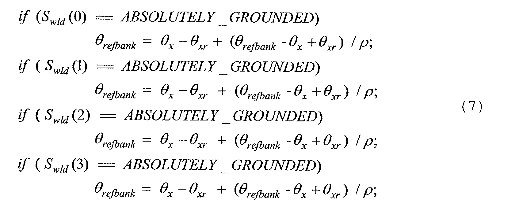
- With the above computed refbank, b_to_r-2 can be computed as:
- If one or two wheels at the same side of the vehicle are lifted, the above computation for b_to_r-2 is no longer accurate since the wheel departure angle a_to_r has been counted as part of the road bank angle. It is natural to use the calculated wheel departure angle to correct this. This consideration leads to the following integrated algorithm between b_to_r-1 and b _to_r-2 .
- Considering the above, the first b_to _r-1 as in equation (4) or
step 90. In order to bring the calculated wheel departure angle for correction, the time when the wheel or the wheels are actually lifted is determined. Due to the potential delay in the wheel lift detections, an extended version of wheel lifting conditions have been used. Those conditions include large magnitude of the suspension relative roll angle xr, aggressive transitional maneuver (characterized by pre-charge active flags), and the wheel lifting flags. Consider the case when the vehicle is turned to left, i.e., positive roll angles are determined.where b_to _r- 1 is computed as in equation (4). Consider that during double wheel lifting, a more aggressive braking pressure to control the vehicle roll is needed. A boosted body-to-road relative roll angle is calculated based on a scaled b_to_r-1:

- Similarly when the vehicle is turning right, the following computations are used for b_to_r-2:and for double wheel lifting


- With the above two computations of body-to-road relative roll angle, a third version can be obtained as the linear combination of the two body to road angles. That is, a final body to road angle is determined in
step 94. - Based on the final body to road angle, at least one
safety system 38, such as systems 40-45 for the automotive vehicle can be controlled. For example, brakes or steering may be applied to prevent the vehicle from rolling over. - While particular embodiments of the invention have been shown and described, numerous variations and alternate embodiments will occur to those skilled in the art. Accordingly, it is intended that the invention be limited only in terms of the appended claims.
Claims (10)
- A method for controlling a safety system (38) of an automotive vehicle (10) comprises:determining a first body to road angle;determining a second body to road angle;determining a final body to road angle from the first body to road angle and the second body to road angle; andcontrolling a safety system (38) in response to the final body to road signal.
- A method as recited in claim 1 wherein determining a first body to road angle comprises determining a first body to road angle from a wheel departure angle.
- A method as recited in claim 1 wherein determining a first body to road angle comprises determining a first body to road angle from a wheel departure angle and a global roll angle.
- A method as recited in claim 1 wherein determining a second body to road angle comprises determining a second body to road angle in response to a global roll angle and a reference bank angle.
- A method as recited in claim 4 further comprising determining the reference bank angle in response to a wheel lift status.
- A method as recited in claim 4 further comprising determining the reference bank angle in response to a wheel lift status, the global roll angle, and the relative roll angle.
- A method as recited in claim 4 further comprising determining the reference bank angle in response to a wheel lift status, a pre-charge status, the global roll angle, and the first body to road angle.
- A method as recited in claim 1 wherein determining a second body to road angle comprises determining a second body to road angle in response to a smoothing ratio, a relative roll angle, and a previous second body to roll angle.
- A method as recited in claim 8 wherein when a two wheel lift status is present, determining the first body to road angle as a function of a scaling factor, a relative roll angle and a wheel departure angle.
- A method as recited in claim 8 further comprising multiplying the scaling factor by the relative roll angle.
Applications Claiming Priority (10)
| Application Number | Priority Date | Filing Date | Title |
|---|---|---|---|
| US40037602P | 2002-08-01 | 2002-08-01 | |
| US40026102P | 2002-08-01 | 2002-08-01 | |
| US40017202P | 2002-08-01 | 2002-08-01 | |
| US40037502P | 2002-08-01 | 2002-08-01 | |
| US400261P | 2002-08-01 | ||
| US400376P | 2002-08-01 | ||
| US400375P | 2002-08-01 | ||
| US400172P | 2002-08-01 | ||
| US10/610,279 US7003389B2 (en) | 2002-08-01 | 2003-06-30 | System and method for characterizing vehicle body to road angle for vehicle roll stability control |
| US610279 | 2003-06-30 |
Publications (2)
| Publication Number | Publication Date |
|---|---|
| EP1386808A1 true EP1386808A1 (en) | 2004-02-04 |
| EP1386808B1 EP1386808B1 (en) | 2011-07-06 |
Family
ID=30119460
Family Applications (1)
| Application Number | Title | Priority Date | Filing Date |
|---|---|---|---|
| EP03254820A Expired - Fee Related EP1386808B1 (en) | 2002-08-01 | 2003-07-31 | System and method for characterizing vehicle body to road angle for vehicle roll stability control |
Country Status (2)
| Country | Link |
|---|---|
| US (1) | US7003389B2 (en) |
| EP (1) | EP1386808B1 (en) |
Cited By (3)
| Publication number | Priority date | Publication date | Assignee | Title |
|---|---|---|---|---|
| WO2008003346A1 (en) * | 2006-07-07 | 2008-01-10 | Continental Automotive Gmbh | Method and system for processing the sensor signals of a motor vehicle |
| WO2014094933A1 (en) * | 2012-12-20 | 2014-06-26 | Daimler Ag | Method for combined determining of a momentary roll angle of a motor vehicle and a momentary roadway cross slope of a curved roadway section traveled by the motor vehicle |
| CN111753716A (en) * | 2020-06-23 | 2020-10-09 | 中国联合网络通信集团有限公司 | Parking line pressing detection method and server |
Families Citing this family (17)
| Publication number | Priority date | Publication date | Assignee | Title |
|---|---|---|---|---|
| US6961648B2 (en) * | 2002-08-05 | 2005-11-01 | Ford Motor Company | System and method for desensitizing the activation criteria of a rollover control system |
| DE10303924A1 (en) * | 2003-01-31 | 2004-08-19 | Knorr-Bremse Systeme für Nutzfahrzeuge GmbH | Method for increasing the driving stability of a vehicle |
| US9162656B2 (en) * | 2003-02-26 | 2015-10-20 | Ford Global Technologies, Llc | Active driven wheel lift identification for an automotive vehicle |
| US7653471B2 (en) * | 2003-02-26 | 2010-01-26 | Ford Global Technologies, Llc | Active driven wheel lift identification for an automotive vehicle |
| JP4427964B2 (en) * | 2003-03-31 | 2010-03-10 | 株式会社アドヴィックス | Vehicle control device |
| US7502675B2 (en) * | 2004-04-01 | 2009-03-10 | Delphi Technologies, Inc. | Feedforward control of motor vehicle roll angle |
| US7191047B2 (en) * | 2004-09-27 | 2007-03-13 | Delphi Technologies, Inc. | Motor vehicle control using a dynamic feedforward approach |
| US7640081B2 (en) * | 2004-10-01 | 2009-12-29 | Ford Global Technologies, Llc | Roll stability control using four-wheel drive |
| DE602004007270T2 (en) * | 2004-10-01 | 2008-02-21 | Delphi Technologies, Inc., Troy | Method and system for detecting a vehicle rollover |
| US7715965B2 (en) | 2004-10-15 | 2010-05-11 | Ford Global Technologies | System and method for qualitatively determining vehicle loading conditions |
| US7668645B2 (en) | 2004-10-15 | 2010-02-23 | Ford Global Technologies | System and method for dynamically determining vehicle loading and vertical loading distance for use in a vehicle dynamic control system |
| DE102005054141A1 (en) * | 2005-11-14 | 2007-05-16 | Bosch Gmbh Robert | Method for determining the tire diameter of a motor vehicle |
| WO2008123984A1 (en) * | 2007-04-02 | 2008-10-16 | Trw Automotive U.S. Llc | Apparatus and method for detecting vehicle rollover using an enhanced algorithm having lane departure sensor inputs |
| US7573375B2 (en) * | 2007-05-02 | 2009-08-11 | Paccar Inc | Rollover prediction and warning method |
| US20100131141A1 (en) * | 2008-11-21 | 2010-05-27 | Gm Global Technology Operations, Inc. | Bank angle estimation via vehicle lateral velocity with force tables |
| US8498773B2 (en) * | 2010-05-20 | 2013-07-30 | GM Global Technology Operations LLC | Stability enhancing system and method for enhancing the stability of a vehicle |
| WO2021026258A1 (en) * | 2019-08-08 | 2021-02-11 | Magna International Inc. | Hydro-elastic suspension system |
Citations (7)
| Publication number | Priority date | Publication date | Assignee | Title |
|---|---|---|---|---|
| EP0940273A2 (en) * | 1998-03-06 | 1999-09-08 | Toyota Jidosha Kabushiki Kaisha | Device for estimating rolling condition of vehicle body with limits of roll angle and angular speed |
| US6038495A (en) * | 1998-02-06 | 2000-03-14 | Delco Electronics Corporation | Vehicle rollover sensing using short-term integration |
| EP1002709A2 (en) * | 1998-11-19 | 2000-05-24 | Delphi Technologies, Inc. | Vehicle attitude angle estimation using sensed signal blending |
| WO2001044020A1 (en) * | 1999-12-16 | 2001-06-21 | Siemens Aktiengesellschaft | Method and device for determining the absolute angle of rotation of an object that is rotating around an approximately horizontal rotational axis |
| US6282471B1 (en) | 1998-06-09 | 2001-08-28 | Land Rover Group Limited | Vehicle roll control |
| US20020082749A1 (en) * | 1999-12-21 | 2002-06-27 | Meyers Joseph Carr | Roll over stability control for an automotive vehicle having rear wheel steering |
| US6556908B1 (en) | 2002-03-04 | 2003-04-29 | Ford Global Technologies, Inc. | Attitude sensing system for an automotive vehicle relative to the road |
Family Cites Families (126)
| Publication number | Priority date | Publication date | Assignee | Title |
|---|---|---|---|---|
| US2917126A (en) | 1957-04-04 | 1959-12-15 | Nolan Phillips | Driving control safety mechanism for tractors |
| US3604273A (en) | 1968-11-25 | 1971-09-14 | Aviat Electric Ltd | Angular rate sensor |
| US3608925A (en) | 1969-05-07 | 1971-09-28 | Peter H Murphy | Apparatus for offsetting centrifugal force affecting motor vehicles |
| US3899028A (en) | 1972-03-30 | 1975-08-12 | Systron Donner Corp | Angular position sensing and control system, apparatus and method |
| US4023864A (en) | 1973-09-20 | 1977-05-17 | Lang Davis Industries, Inc. | Automatic stability control system with strain gauge sensors |
| US3972543A (en) | 1974-12-06 | 1976-08-03 | The Bendix Corporation | Combination vehicle yaw stabilizer |
| US3948567A (en) | 1975-02-12 | 1976-04-06 | The Bendix Corporation | Sway control means for a trailer |
| USRE30550E (en) | 1975-11-06 | 1981-03-24 | Durrell U. Howard | Automatic trailer sway sensing and brake applying system |
| JPS6015015B2 (en) | 1979-06-29 | 1985-04-17 | 株式会社 レオ技研 | Road moisture detection device |
| JPS58152793A (en) | 1982-03-05 | 1983-09-10 | ティー・シー・エム株式会社 | Device for preventing turning-sideways of transport car |
| JPS60163770A (en) | 1984-02-02 | 1985-08-26 | Honda Motor Co Ltd | Steering device for vehicle |
| US4592565A (en) | 1984-10-17 | 1986-06-03 | Leo Eagle | Apparatus for detecting an overturning moment in a moving vehicle, and jackknifing in a trailer-truck combination |
| JPH06104455B2 (en) | 1985-03-15 | 1994-12-21 | 日産自動車株式会社 | Vehicle motion condition estimation device |
| US4650212A (en) | 1985-03-20 | 1987-03-17 | Mazda Motor Corporation | Vehicle suspension system |
| US4767588A (en) | 1985-04-13 | 1988-08-30 | Nissan Motor Co., Ltd. | Vehicle control system for controlling side slip angle and yaw rate gain |
| JP2532059B2 (en) | 1985-09-13 | 1996-09-11 | 日産自動車株式会社 | Vehicle suspension control device |
| JPH0629039B2 (en) | 1986-01-10 | 1994-04-20 | 日産自動車株式会社 | Vehicle motion state estimation device |
| DE3606797C2 (en) | 1986-03-01 | 2000-11-23 | Bosch Gmbh Robert | Device and method for controlling, in particular for limiting, the driving speed of a road vehicle |
| US4761022A (en) | 1986-03-08 | 1988-08-02 | Toyota Jidosha Kabushiki Kaisha | Suspension controller for improved turning |
| JPH0694253B2 (en) | 1986-03-17 | 1994-11-24 | トヨタ自動車株式会社 | Roll control device for vehicle |
| JPS62291067A (en) | 1986-06-10 | 1987-12-17 | Nec Corp | Manufacture of thin film transistor |
| JPH0829649B2 (en) | 1987-03-31 | 1996-03-27 | 日産自動車株式会社 | Active suspension device |
| DE3821610A1 (en) | 1988-06-27 | 1989-12-28 | Bayerische Motoren Werke Ag | CONTROL DEVICE FOR STABILIZING A VEHICLE |
| JPS6432918A (en) | 1987-07-28 | 1989-02-02 | Mitsubishi Motors Corp | Active suspension controller |
| DE3826982C2 (en) | 1987-08-10 | 2000-11-30 | Denso Corp | Auxiliary steering system connected to an anti-lock control system for use in motor vehicles |
| DE3877118T2 (en) | 1987-10-15 | 1993-07-01 | Mazda Motor | DEVICE FOR DETERMINING THE FRICTION FACTOR FOR VEHICLES. |
| JPH01122716A (en) | 1987-11-05 | 1989-05-16 | Hitachi Ltd | Active suspension control system for automobile |
| DE3738221A1 (en) | 1987-11-11 | 1989-06-08 | Bayerische Motoren Werke Ag | METHOD AND DEVICE FOR DETECTING THE STATE OF A ROAD |
| JP2618250B2 (en) | 1987-12-22 | 1997-06-11 | 富士重工業株式会社 | Traction control device |
| DE3804587A1 (en) | 1988-02-13 | 1989-08-24 | Daimler Benz Ag | ADDITIONAL STEERING |
| DE3805589A1 (en) | 1988-02-23 | 1989-08-31 | Lucas Ind Plc | METHOD AND DEVICE FOR CONTROLLING A BRAKE SYSTEM FOR HEAVY VEHICLES |
| US4898431A (en) | 1988-06-15 | 1990-02-06 | Aisin Seiki Kabushiki Kaisha | Brake controlling system |
| US5313389A (en) | 1988-09-13 | 1994-05-17 | Aisin Seiki Kabushiki Kaisha | Fail-safe mechanism for vehicle stability augmentation steering system |
| JP2768710B2 (en) | 1988-09-17 | 1998-06-25 | ローベルト・ボッシュ・ゲゼルシャフト・ミット・ベシュレンクテル・ハフツング | A device that activates a protection device that protects a vehicle occupant |
| JP2565384B2 (en) | 1988-09-30 | 1996-12-18 | 富士重工業株式会社 | Control device for automobile active suspension |
| GB8825540D0 (en) | 1988-11-01 | 1988-12-07 | Jaguar Cars | Air bag restraint systems |
| JPH0732331Y2 (en) | 1989-01-18 | 1995-07-26 | 日産自動車株式会社 | Vehicle steering control device |
| US4998593A (en) | 1989-03-31 | 1991-03-12 | Aisin Seiki Kabushiki Kaisha | Steering and brake controlling system |
| US5239868A (en) | 1989-05-19 | 1993-08-31 | Matsushita Electric Industrial Co., Ltd. | Angular rate detecting device |
| JP2867448B2 (en) | 1989-08-11 | 1999-03-08 | 株式会社日立製作所 | Active suspension control device |
| JPH0396468A (en) | 1989-09-07 | 1991-04-22 | Honda Motor Co Ltd | Estimation method for fore and aft acceleration and deceleration of body |
| JPH0833408B2 (en) | 1990-03-29 | 1996-03-29 | 株式会社日立製作所 | Angle detection device, translational acceleration detection device, and vehicle control device |
| US5265020A (en) | 1990-04-20 | 1993-11-23 | Mazda Motor Corporation | Torque distribution control apparatus for four wheel drive |
| JP2762711B2 (en) | 1990-07-02 | 1998-06-04 | 日産自動車株式会社 | Vehicle braking behavior compensator |
| JP2600986B2 (en) | 1990-07-06 | 1997-04-16 | 三菱自動車工業株式会社 | Rear wheel steering control method |
| JP2679415B2 (en) | 1990-12-21 | 1997-11-19 | 日産自動車株式会社 | Vehicle braking force left / right distribution control device |
| US5408411A (en) | 1991-01-18 | 1995-04-18 | Hitachi, Ltd. | System for predicting behavior of automotive vehicle and for controlling vehicular behavior based thereon |
| DE4121954A1 (en) | 1991-07-03 | 1993-01-07 | Bosch Gmbh Robert | METHOD FOR OBTAINING THE YEAR SPEED AND / OR THE LATERAL SPEED |
| US5282134A (en) | 1991-08-19 | 1994-01-25 | Automotive Systems Laboratory, Inc. | Slant transform/signal space crash discriminator |
| US5324102A (en) | 1991-10-18 | 1994-06-28 | Fag Kugelfischer Georg Schafer Kgaa | Method and apparatus for regulating the braking force of motorcycles |
| US5335176A (en) | 1991-12-02 | 1994-08-02 | Koyo Seiko Co., Ltd. | Safety system for vehicles |
| JP3197330B2 (en) | 1992-04-10 | 2001-08-13 | 本田技研工業株式会社 | Vehicle driving force control device |
| US5548536A (en) | 1992-05-16 | 1996-08-20 | Daimler-Benz Ag | Method for determining quantities which characterize the driving behavior |
| DE4226746C1 (en) | 1992-08-13 | 1993-10-07 | Daimler Benz Ag | Method for determining a driving-dependent steering angle |
| DE4228414B4 (en) * | 1992-08-26 | 2006-11-16 | Robert Bosch Gmbh | Method and device for processing sensor signals |
| DE4228893B4 (en) | 1992-08-29 | 2004-04-08 | Robert Bosch Gmbh | System for influencing the driving dynamics of a motor vehicle |
| US5278761A (en) | 1992-11-12 | 1994-01-11 | Ford Motor Company | Method for vehicular wheel spin control that adapts to different road traction characteristics |
| JP2882232B2 (en) | 1993-03-17 | 1999-04-12 | 三菱自動車工業株式会社 | Vehicle weight center slip angle measuring device |
| US5446548A (en) * | 1993-10-08 | 1995-08-29 | Siemens Medical Systems, Inc. | Patient positioning and monitoring system |
| JP3303500B2 (en) | 1994-02-02 | 2002-07-22 | トヨタ自動車株式会社 | Vehicle behavior control device |
| DE4405379A1 (en) | 1994-02-19 | 1995-08-24 | Bosch Gmbh Robert | ABS braking system for vehicle |
| KR950028978A (en) | 1994-04-06 | 1995-11-22 | 전성원 | Shift pattern control device and method for steep slope and steep curve |
| KR100207106B1 (en) | 1994-04-06 | 1999-07-15 | 정몽규 | Method and apparatus of taper for automobile testing road |
| US5446658A (en) | 1994-06-22 | 1995-08-29 | General Motors Corporation | Method and apparatus for estimating incline and bank angles of a road surface |
| JP3116738B2 (en) | 1994-07-28 | 2000-12-11 | トヨタ自動車株式会社 | Vehicle behavior control device |
| US5610575A (en) | 1994-08-25 | 1997-03-11 | Automotive Systems Laboratory, Inc. | Method and system for detecting vehicle roll-over |
| US5602734A (en) | 1994-09-23 | 1997-02-11 | Advanced Safety Concepts, Inc. | Automobile air bag systems |
| JP3050061B2 (en) | 1994-10-25 | 2000-06-05 | トヨタ自動車株式会社 | Occupant restraint |
| US5732379A (en) | 1994-11-25 | 1998-03-24 | Itt Automotive Europe Gmbh | Brake system for a motor vehicle with yaw moment control |
| US5732378A (en) | 1994-11-25 | 1998-03-24 | Itt Automotive Europe Gmbh | Method for determining a wheel brake pressure |
| DE19515060A1 (en) | 1994-11-25 | 1996-05-30 | Teves Gmbh Alfred | Vehicle wheel braking force determn. by reference speed comparison |
| US5732377A (en) | 1994-11-25 | 1998-03-24 | Itt Automotive Europe Gmbh | Process for controlling driving stability with a yaw rate sensor equipped with two lateral acceleration meters |
| US5549328A (en) | 1995-01-17 | 1996-08-27 | Gabriel Ride Control Products, Inc. | Roll control system |
| JPH08258588A (en) | 1995-03-27 | 1996-10-08 | Mazda Motor Corp | Road surface condition detecting device in vehicle |
| JP3463415B2 (en) | 1995-06-22 | 2003-11-05 | 日産自動車株式会社 | Vehicle yawing behavior control device |
| US5648903A (en) | 1995-07-10 | 1997-07-15 | Ford Global Technologies, Inc. | Four wheel steering control utilizing front/rear tire longitudinal slip difference |
| FI108084B (en) | 1995-09-08 | 2001-11-15 | Vaisala Oyj | Method and apparatus for measuring road surface characteristics |
| JP3248411B2 (en) | 1995-10-11 | 2002-01-21 | トヨタ自動車株式会社 | Vehicle behavior control device |
| JP3248413B2 (en) | 1995-10-18 | 2002-01-21 | トヨタ自動車株式会社 | Vehicle behavior control device |
| JP3008833B2 (en) | 1995-10-25 | 2000-02-14 | トヨタ自動車株式会社 | Estimation device for vehicle body skidding speed |
| JP3627325B2 (en) | 1995-11-17 | 2005-03-09 | アイシン精機株式会社 | Vehicle motion control device |
| JP3533420B2 (en) | 1995-12-05 | 2004-05-31 | トヨタ自動車株式会社 | Brake control device |
| DE19602879C1 (en) * | 1996-01-29 | 1997-08-07 | Knorr Bremse Systeme | Method for detecting the risk of a vehicle tipping over |
| AUPN786796A0 (en) | 1996-02-05 | 1996-02-29 | Verward Pty Ltd (trading as Brooks Merchants) | Vehicle seat |
| DE19609717A1 (en) * | 1996-03-13 | 1997-09-18 | Bosch Gmbh Robert | Arrangement for detecting rollover processes in vehicles |
| US5787375A (en) | 1996-04-01 | 1998-07-28 | Ford Global Technologies, Inc. | Method for determining steering position of automotive steering mechanism |
| US5742919A (en) | 1996-04-26 | 1998-04-21 | Ford Global Technologies, Inc. | Method and apparatus for dynamically determining a lateral velocity of a motor vehicle |
| US5809434A (en) | 1996-04-26 | 1998-09-15 | Ford Global Technologies, Inc. | Method and apparatus for dynamically determically determining an operating state of a motor vehicle |
| US5742918A (en) | 1996-04-26 | 1998-04-21 | Ford Global Technologies, Inc. | Method and apparatus for dynamically compensating a lateral acceleration of a motor vehicle |
| JPH09315277A (en) | 1996-05-31 | 1997-12-09 | Unisia Jecs Corp | Device for controlling movement of vehicle |
| US5707117A (en) | 1996-07-19 | 1998-01-13 | General Motors Corporation | Active brake control diagnostic |
| DE19655388B4 (en) * | 1996-08-16 | 2008-08-14 | Daimler Ag | Vehicle dynamics control system and method |
| DE19634728C1 (en) | 1996-08-28 | 1998-04-02 | Daimler Benz Ag | Vehicle steering |
| US5878357A (en) | 1996-09-03 | 1999-03-02 | Ford Global Technologies, Inc. | Method and apparatus for vehicle yaw rate estimation |
| US5720533A (en) | 1996-10-15 | 1998-02-24 | General Motors Corporation | Brake control system |
| JPH10119743A (en) | 1996-10-23 | 1998-05-12 | Aisin Seiki Co Ltd | Motion control device for vehicle |
| JPH10129439A (en) | 1996-10-25 | 1998-05-19 | Aisin Seiki Co Ltd | Motion controlling device for vehicle |
| US5723782A (en) | 1996-11-29 | 1998-03-03 | Bolles, Jr.; Robert C. | Method of land vehicle suspension evaluation and design through roll angle analysis |
| DE19650691C2 (en) | 1996-12-07 | 1998-10-29 | Deutsch Zentr Luft & Raumfahrt | Method for steering assistance for a driver of a road vehicle |
| US5825284A (en) | 1996-12-10 | 1998-10-20 | Rollover Operations, Llc | System and method for the detection of vehicle rollover conditions |
| US5736939A (en) | 1996-12-11 | 1998-04-07 | Caterpillar Inc. | Apparatus and method for determing a condition of a road |
| GB9626045D0 (en) * | 1996-12-14 | 1997-01-29 | Rover Group | A vehicle roll stabilising system |
| JP3493568B2 (en) * | 1997-02-12 | 2004-02-03 | 光洋精工株式会社 | Car steering system |
| US6085860A (en) * | 1997-03-22 | 2000-07-11 | Robert Bosch Gmbh | Method and apparatus for operating a steering system for a motor vehicle |
| US6186267B1 (en) * | 1997-03-22 | 2001-02-13 | Robert Bosch Gmbh | Method and apparatus for operating a steering system for a motor vehicle |
| JP3269421B2 (en) * | 1997-04-04 | 2002-03-25 | 三菱自動車工業株式会社 | Automatic vehicle deceleration control device |
| JP2001509448A (en) * | 1997-07-01 | 2001-07-24 | ダイナモティヴ エル.エル.スィー. | Anti-rollover brake device |
| US6026926A (en) * | 1997-07-25 | 2000-02-22 | Honda Giken Kogyo Kabushiki Kaisha | Electric power steering apparatus |
| JPH11194089A (en) * | 1997-08-20 | 1999-07-21 | Daimler Benz Ag | Determining method of road surface condition |
| DE19736328A1 (en) * | 1997-08-21 | 1999-02-25 | Bayerische Motoren Werke Ag | Controlling accident protection triggering devices in motor vehicle |
| DE19744085A1 (en) * | 1997-10-06 | 1999-04-08 | Bosch Gmbh Robert | System producing trigger signal for vehicle safety unit with collision with low obstacle |
| US5971503A (en) | 1998-02-03 | 1999-10-26 | Ford Global Technologies, Inc. | Hydraulic control unit with ambient temperature compensation during fluid pressure delivery |
| US6002974A (en) | 1998-02-06 | 1999-12-14 | Delco Electronics Corporation | Vehicle rollover sensing using extended kalman filter |
| US5946644A (en) | 1998-03-30 | 1999-08-31 | Chrysler Corporation | Steering center indicator device |
| US6089344A (en) * | 1998-06-01 | 2000-07-18 | Ford Global Technologies, Inc. | Method and apparatus for determining the center position of a steering system |
| JP3252797B2 (en) * | 1998-06-19 | 2002-02-04 | トヨタ自動車株式会社 | Rollover determination method |
| US6050360A (en) * | 1998-06-24 | 2000-04-18 | General Motors Corporation | Apparatus and method for producing a desired return torque in a vehicle power steering system having a rotational steering position sensor |
| US6073065A (en) * | 1998-09-04 | 2000-06-06 | Ford Global Technologies, Inc. | Method for detecting a bank angle experienced by a moving vehicle |
| US6169939B1 (en) * | 1998-09-08 | 2001-01-02 | Ford Global Technologies, Inc. | Method of generating a vehicle lateral acceleration signal for use in an active tilt control system |
| JP3497746B2 (en) * | 1998-10-26 | 2004-02-16 | 本田技研工業株式会社 | Electric power steering device |
| US6179394B1 (en) * | 1998-11-09 | 2001-01-30 | General Motors Corporation | Active brake balance control method |
| US6062336A (en) * | 1998-11-13 | 2000-05-16 | General Motors Corporation | Adaptive variable effort power steering system |
| US6195606B1 (en) * | 1998-12-07 | 2001-02-27 | General Motors Corporation | Vehicle active brake control with bank angle compensation |
| US6185485B1 (en) * | 1998-12-22 | 2001-02-06 | Ford Global Technologies, Inc | Relative vehicle platform having synchronized adaptive offset calibration for lateral accelerometer and steering angle sensor |
| US6438463B1 (en) * | 1999-09-06 | 2002-08-20 | Honda Giken Kogyo Kabushiki Kaisha | Process for determining lateral overturning of vehicle, and system for detecting inclination angle of vehicle body |
| US6263261B1 (en) * | 1999-12-21 | 2001-07-17 | Ford Global Technologies, Inc. | Roll over stability control for an automotive vehicle |
-
2003
- 2003-06-30 US US10/610,279 patent/US7003389B2/en not_active Expired - Lifetime
- 2003-07-31 EP EP03254820A patent/EP1386808B1/en not_active Expired - Fee Related
Patent Citations (7)
| Publication number | Priority date | Publication date | Assignee | Title |
|---|---|---|---|---|
| US6038495A (en) * | 1998-02-06 | 2000-03-14 | Delco Electronics Corporation | Vehicle rollover sensing using short-term integration |
| EP0940273A2 (en) * | 1998-03-06 | 1999-09-08 | Toyota Jidosha Kabushiki Kaisha | Device for estimating rolling condition of vehicle body with limits of roll angle and angular speed |
| US6282471B1 (en) | 1998-06-09 | 2001-08-28 | Land Rover Group Limited | Vehicle roll control |
| EP1002709A2 (en) * | 1998-11-19 | 2000-05-24 | Delphi Technologies, Inc. | Vehicle attitude angle estimation using sensed signal blending |
| WO2001044020A1 (en) * | 1999-12-16 | 2001-06-21 | Siemens Aktiengesellschaft | Method and device for determining the absolute angle of rotation of an object that is rotating around an approximately horizontal rotational axis |
| US20020082749A1 (en) * | 1999-12-21 | 2002-06-27 | Meyers Joseph Carr | Roll over stability control for an automotive vehicle having rear wheel steering |
| US6556908B1 (en) | 2002-03-04 | 2003-04-29 | Ford Global Technologies, Inc. | Attitude sensing system for an automotive vehicle relative to the road |
Cited By (6)
| Publication number | Priority date | Publication date | Assignee | Title |
|---|---|---|---|---|
| WO2008003346A1 (en) * | 2006-07-07 | 2008-01-10 | Continental Automotive Gmbh | Method and system for processing the sensor signals of a motor vehicle |
| WO2014094933A1 (en) * | 2012-12-20 | 2014-06-26 | Daimler Ag | Method for combined determining of a momentary roll angle of a motor vehicle and a momentary roadway cross slope of a curved roadway section traveled by the motor vehicle |
| CN104853941A (en) * | 2012-12-20 | 2015-08-19 | 戴姆勒股份公司 | Method for combined determining of a momentary roll angle of a motor vehicle and a momentary roadway cross slope of a curved roadway section traveled by the motor vehicle |
| US9849886B2 (en) | 2012-12-20 | 2017-12-26 | Daimler Ag | Method for combined determining of a momentary roll angle of a motor vehicle and a momentary roadway cross slope of a curved roadway section traveled by the motor vehicle |
| CN111753716A (en) * | 2020-06-23 | 2020-10-09 | 中国联合网络通信集团有限公司 | Parking line pressing detection method and server |
| CN111753716B (en) * | 2020-06-23 | 2023-11-24 | 中国联合网络通信集团有限公司 | Parking line pressing detection method and server |
Also Published As
| Publication number | Publication date |
|---|---|
| US7003389B2 (en) | 2006-02-21 |
| EP1386808B1 (en) | 2011-07-06 |
| US20040064237A1 (en) | 2004-04-01 |
Similar Documents
| Publication | Publication Date | Title |
|---|---|---|
| US7079928B2 (en) | System and method for determining a wheel departure angle for a rollover control system with respect to road roll rate and loading misalignment | |
| US6684140B2 (en) | System for sensing vehicle global and relative attitudes using suspension height sensors | |
| US6631317B2 (en) | Attitude sensing system for an automotive vehicle | |
| US6556908B1 (en) | Attitude sensing system for an automotive vehicle relative to the road | |
| US6718248B2 (en) | System for detecting surface profile of a driving road | |
| US7003389B2 (en) | System and method for characterizing vehicle body to road angle for vehicle roll stability control | |
| US6593849B2 (en) | Wheel lift identification for an automotive vehicle | |
| US7451032B2 (en) | System and method for determining desired yaw rate and lateral velocity for use in a vehicle dynamic control system | |
| EP1346856B1 (en) | A system and method for determining the roll angle of a vehicle | |
| EP1386807B1 (en) | System and method for determining a wheel departure angle for a rollover control system | |
| US7676307B2 (en) | System and method for controlling a safety system of a vehicle in response to conditions sensed by tire sensors related applications | |
| US6834218B2 (en) | Roll over stability control for an automotive vehicle | |
| US7877200B2 (en) | System and method for dynamically determining vehicle loading and vertical loading distance for use in a vehicle dynamic control system | |
| US7277787B2 (en) | System and method for desensitizing the activation criteria of a rollover control system | |
| EP1479581A1 (en) | An integrated sensing system for an automotive system | |
| US6725140B2 (en) | Method and apparatus for determining lateral velocity of a motor vehicle in closed form for all road and driving conditions | |
| GB2434127A (en) | A method for dynamically determining axle loadings of a movingvehicle | |
| EP1386801B1 (en) | System and method for characterizing the road bank for vehicle roll stability control | |
| US7430468B2 (en) | System and method for sensitizing the activation criteria of a rollover control system |
Legal Events
| Date | Code | Title | Description |
|---|---|---|---|
| PUAI | Public reference made under article 153(3) epc to a published international application that has entered the european phase |
Free format text: ORIGINAL CODE: 0009012 |
|
| AK | Designated contracting states |
Kind code of ref document: A1 Designated state(s): AT BE BG CH CY CZ DE DK EE ES FI FR GB GR HU IE IT LI LU MC NL PT RO SE SI SK TR |
|
| AX | Request for extension of the european patent |
Extension state: AL LT LV MK |
|
| 17P | Request for examination filed |
Effective date: 20040804 |
|
| AKX | Designation fees paid |
Designated state(s): DE FR GB SE |
|
| 17Q | First examination report despatched |
Effective date: 20050518 |
|
| RAP1 | Party data changed (applicant data changed or rights of an application transferred) |
Owner name: FORD GLOBAL TECHNOLOGIES, LLC. |
|
| 17Q | First examination report despatched |
Effective date: 20050518 |
|
| GRAP | Despatch of communication of intention to grant a patent |
Free format text: ORIGINAL CODE: EPIDOSNIGR1 |
|
| RIC1 | Information provided on ipc code assigned before grant |
Ipc: B60T 8/1755 20060101AFI20101129BHEP |
|
| GRAS | Grant fee paid |
Free format text: ORIGINAL CODE: EPIDOSNIGR3 |
|
| GRAA | (expected) grant |
Free format text: ORIGINAL CODE: 0009210 |
|
| AK | Designated contracting states |
Kind code of ref document: B1 Designated state(s): DE FR GB SE |
|
| REG | Reference to a national code |
Ref country code: GB Ref legal event code: FG4D |
|
| REG | Reference to a national code |
Ref country code: DE Ref legal event code: R096 Ref document number: 60337616 Country of ref document: DE Effective date: 20110908 |
|
| REG | Reference to a national code |
Ref country code: SE Ref legal event code: TRGR |
|
| PLBE | No opposition filed within time limit |
Free format text: ORIGINAL CODE: 0009261 |
|
| STAA | Information on the status of an ep patent application or granted ep patent |
Free format text: STATUS: NO OPPOSITION FILED WITHIN TIME LIMIT |
|
| 26N | No opposition filed |
Effective date: 20120411 |
|
| REG | Reference to a national code |
Ref country code: DE Ref legal event code: R097 Ref document number: 60337616 Country of ref document: DE Effective date: 20120411 |
|
| REG | Reference to a national code |
Ref country code: FR Ref legal event code: PLFP Year of fee payment: 14 |
|
| REG | Reference to a national code |
Ref country code: FR Ref legal event code: PLFP Year of fee payment: 15 |
|
| REG | Reference to a national code |
Ref country code: FR Ref legal event code: PLFP Year of fee payment: 16 |
|
| PGFP | Annual fee paid to national office [announced via postgrant information from national office to epo] |
Ref country code: FR Payment date: 20180620 Year of fee payment: 16 |
|
| PGFP | Annual fee paid to national office [announced via postgrant information from national office to epo] |
Ref country code: DE Payment date: 20180618 Year of fee payment: 16 Ref country code: GB Payment date: 20180625 Year of fee payment: 16 |
|
| PGFP | Annual fee paid to national office [announced via postgrant information from national office to epo] |
Ref country code: SE Payment date: 20180710 Year of fee payment: 16 |
|
| REG | Reference to a national code |
Ref country code: DE Ref legal event code: R119 Ref document number: 60337616 Country of ref document: DE |
|
| GBPC | Gb: european patent ceased through non-payment of renewal fee |
Effective date: 20190731 |
|
| REG | Reference to a national code |
Ref country code: SE Ref legal event code: EUG |
|
| PG25 | Lapsed in a contracting state [announced via postgrant information from national office to epo] |
Ref country code: SE Free format text: LAPSE BECAUSE OF NON-PAYMENT OF DUE FEES Effective date: 20190801 Ref country code: DE Free format text: LAPSE BECAUSE OF NON-PAYMENT OF DUE FEES Effective date: 20200201 Ref country code: GB Free format text: LAPSE BECAUSE OF NON-PAYMENT OF DUE FEES Effective date: 20190731 |
|
| PG25 | Lapsed in a contracting state [announced via postgrant information from national office to epo] |
Ref country code: FR Free format text: LAPSE BECAUSE OF NON-PAYMENT OF DUE FEES Effective date: 20190731 |