EP1376755A1 - A telecommunications antenna support structure - Google Patents
A telecommunications antenna support structure Download PDFInfo
- Publication number
- EP1376755A1 EP1376755A1 EP03394053A EP03394053A EP1376755A1 EP 1376755 A1 EP1376755 A1 EP 1376755A1 EP 03394053 A EP03394053 A EP 03394053A EP 03394053 A EP03394053 A EP 03394053A EP 1376755 A1 EP1376755 A1 EP 1376755A1
- Authority
- EP
- European Patent Office
- Prior art keywords
- antennae
- pole
- cover
- support structure
- telecommunications
- Prior art date
- Legal status (The legal status is an assumption and is not a legal conclusion. Google has not performed a legal analysis and makes no representation as to the accuracy of the status listed.)
- Withdrawn
Links
Images


Classifications
-
- H—ELECTRICITY
- H01—ELECTRIC ELEMENTS
- H01Q—ANTENNAS, i.e. RADIO AERIALS
- H01Q1/00—Details of, or arrangements associated with, antennas
- H01Q1/12—Supports; Mounting means
- H01Q1/1242—Rigid masts specially adapted for supporting an aerial
-
- H—ELECTRICITY
- H01—ELECTRIC ELEMENTS
- H01Q—ANTENNAS, i.e. RADIO AERIALS
- H01Q1/00—Details of, or arrangements associated with, antennas
- H01Q1/06—Means for the lighting or illuminating of antennas, e.g. for purpose of warning
-
- H—ELECTRICITY
- H01—ELECTRIC ELEMENTS
- H01Q—ANTENNAS, i.e. RADIO AERIALS
- H01Q1/00—Details of, or arrangements associated with, antennas
- H01Q1/42—Housings not intimately mechanically associated with radiating elements, e.g. radome
Definitions
- the present invention relates to the field of telecommunication support structures for antennae.
- the telecommunication of interest in the present invention are wireless communication where the support structure supports antennae which are used to receive and/or transmit communications signals, for example radio, television or telephone communication signals.
- communications signals for example radio, television or telephone communication signals.
- the present invention is the field of mobile phone communications and telecommunications antennae support structures for use therewith.
- the structures often form part of a telecommunications base station.
- Telecommunications antennae support structures have been long known. Increasingly however it is desired to place the support structures (usually as part of a base station) in areas that have relatively high populations. For example in order to support a mobile phone network it is desirable that increasing numbers of telecommunications antennae support structures are used to transmit and receive mobile phone communication signals for many users and also to provide strong signals so that calls made are clear (voice data and other data is not corrupted or distorted) and are not inadvertently dropped also and of course to ensure that the telecommunications network is available at all geographic locations within a certain area. Planning authorities do not like some structures which can devalue properties and can be reluctant to grant permission to erect the structures.
- camouflage antennae for example by creating an antennae support structure that resembles a tree. Such structures are designed so that their function is not immediately evident.
- An objective of the present invention is to provide an alternative solution to the problems associated with prior art telecommunication antennae support structure.
- the word “antennae” means a transmitting or receiving device for telecommunications and includes what is commonly known as a dish.
- the present invention provides a telecommunications antennae support structure comprising:
- the present invention also provides a telecommunications antennae support structure comprising:
- the present invention also provides a telecommunications antennae support structure comprising:
- the latter two embodiments also include a work platform such as described above.
- the present invention provides a simple yet attractive solution to the problems recited above. It is particularly desirable that the support structure of the invention is arranged to resemble a street lamp, in particular a street lamp having at least two lights. The arrangement is particularly designed to resemble a lamp standard.
- the supporting pole is located centrally to the arrangement.
- a structure is often referred to as a monopole structure.
- the pole is desirably a straight pole optionally formed by two or more pole portions.
- the pole sections may be fitted end to end or joined side to side to form the pole.
- part of the pole (the part supporting the arms) is constructed of metal such as steel; while the remainder of the pole is formed of an alternative material, desirably a castable material such as concrete.
- the entire pole, whether in pole portions or not can be made of the same material.
- the pole is provided with one or more conduits for receiving cables running to and/or from the antennae.
- the supporting pole is hollow. This allows cables to be accommodated internally in the pole.
- the supporting pole is additionally or alternatively provided with recessed channels (or grooves) on an exterior thereof.
- recessed channels or grooves
- the channels run longitudinally (preferably in a straight line) from the base of the pole upwards.
- At least one antennae is provided on the top of the pole.
- Some particularly desirable arrangements include those having at least one antennae on the top of the pole and two, three or four arms (each supporting desirably at least on antennae) mounted on or arranged independently about the pole.
- the antennae/cover arrangement on the top of the pole is substantially centred about a longitudinal axis of the pole (again desirably in a manner resembling a street lamp).
- the arms are non-linear for example curved.
- the arms curve downwardly toward the base of the pole so that the second free end thereof is at a position lower than the first end thereof relative to the pole.
- the arm may first extend upwardly and then downwardly or vice versa, in all cases desirably in a full or partial "s" or “u” shape. This allows for design of particularly attractive structures. It is particularly desirable that the arm has at least one generally u-shaped portion which is up-turned toward the top of the pole or down-turned towards the base of the pole.
- the antennae may be placed on the up-turned end of the arm so that each of the arm forms a mounting base for the antennae, so that if desired the antennae and/any associated cover may be centred about a longitudinal axis of the arm(s).
- the antennae may sit higher than the general u-shape.
- the antennae are attached to the down-turned end (again desirably the antennae and/or cover are centred about a longitudinal axis of the arm) of the arm so that it can be mounted at a position lower than the general U-shape arrangement.
- the arms are each of a general S-shape (in general having at least two bends in the arm).
- any single antennae or a group of antennae provided on a free end of any given arm is/are cover by a cover. It will be appreciated that additional (“dummy") covers which do not house an antennae can be provided, for example, for aesthetic reasons. It is particularly desirable that any cover provided surrounds (and desirably entirely houses) the antennae. One particularly desirable arrangement is where the cover fits over the antennae. In particular it is desirable that the cover surrounds the antennae and obscures it from view.
- the cover surrounds the arm on all sides with an aperture provided in the cover through which the antennae and/or the arm extends to allow the antennae and the arms to be fixed one to another.
- the covers are each globe shaped.
- the term globe as used herein refers to a continuous solid cover (desirably with an aperture as described immediately above) and optionally with a top cover/lid. It is desirable that the cover is a continuous solid (a closed cover) and may for example be transparent, translucent or opaque to visible light. Desirably it is translucent. It is particularly desirable that the cover does not interfere to any substantial extent with the telecommunication signals emitted or received by the antennae.
- One particular material which is useful for construction of the covers of the structure of the present invention is fibreglass reinforced plastic (FRP).
- FRP fibreglass reinforced plastic
- the cover can also be consider a protective shell and/or camouflage.
- the wall thickness of the covers is desirably between 3 - 6mm.
- the covers are desirably weatherproof.
- the cover is of curvilinear shape, for example, of a spherical, elliptical or other such shapes, through it will be appreciated that it could have irregular/angular shapes.
- the covers are translucent to visible light, i.e. sufficiently opaque to obscure the view of the antennae, but not so opaque that the covers may not transmit visible light e.g. from an internal visible light source to the exterior thereof.
- the cover is divided in two or more parts which can be opened to allow access to the interior of the cover (and thus the antennae).
- the cover has a top wall portion, side-wall portions and a base. Desirably an aperture is provide in the base.
- the side-walls surround the antennae when in situ.
- the top-wall portion desirably covers over the top of the antennae (in situ).
- the present invention extends to covers employed in the present invention.
- the cover is provided in at least two portions for example as two parts which are relatively movable to open (preferable providing an opening in the side wall thereof). This may be done, for example by providing the cover in two or more parts joined along one or more longitudinal and/or transverse joints. Preferably at least one longitudinal joint is provided (which in use runs top to bottom along the side-wall of the cover). Alternatively a removable or hinged portion may be provided in the side wall to form for example an access door.
- the cover is desirably formed by two part shells (desirably substantially half shells) and the top portion is formed by a lid which mates with the shells. It is also particularly desirable to form the cover in three portions (desirably substantially each a one third portion of the cover) to allow access at three portions about the cover.
- an opening or access point is provided for each antennae or group of antennae provided.
- the cover opens to allow access at three points coinciding with the positions of the antennae.
- the material of the cover is colourable by dyeing with a colorant, for example, a dye or other material which will colour the cover to any particularly desired colour.
- a colorant for example, a dye or other material which will colour the cover to any particularly desired colour.
- the covers of the invention may have a height of 0.5 to 2 metres with a suitable radius for example 0.4 to 1 metre.
- the cover(s) may be supported by the arms and/or the platform.
- the antennae may be single or grouped antennae comprising transmitting and/or receiving devices, for example, including dishes.
- the work platform mounted about the pole is desirable circular in shape and is mounted sufficiently close to the antennae to allow a person to work on the antennae from the platform. Suitable therefore the platform is desirable located within 2m of each (at least those which are radially arranged and desirably within said distances of all antennae) antennae, more preferably within 1.5m of each antennae and where possible within 1m of the antennae.
- the platform may be provided with an access door for access through the platform to the walking distance thereof from the underside thereof.
- the arms turn downwards along the pole it is desirable that they and the platform are arranged so that the antennae (and any associated cover) is proximate the platform.
- the platform is provided about the pole so that a part of an (desirably each) arm between the first fixed end and the second free end thereof passes through the platform.
- the arms are substantially identical in shape and at substantially the same position relative to the pole, this may be achieved relatively easily with the present invention. Allowing the arms to pass through the platform at least once allows the working surface thereof to be placed closer to the antennae/covers that would otherwise be possible.
- the free end of the arms are located proximate to a top (working surface) of the platform.
- the arm passes through the platform twice. For example downward turning through the platform and then turning upwardly again and extending through the platform.
- At least one of the radially arranged antennae /cover assemblies is at least partly supported by the platform.
- the arms could for example be arranged so that all, or a substantial portion of, the weight of the antennae and/or cover is borne by the platform. In such case the arms can be considered to be ornamental though the appearance is still that the antennae /cover is supported by the end of the arm.
- cables for the antennae run in the arms.
- the arms may be hollow to accommodate cables for the antennae. This is a particularly attractive arrangement where the cables may be hidden internally.
- the invention extends to the support structure shown in the accompanying figures.
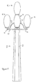
- Figure 1 shows a telecommunications antennae support structure 1 having a central support pole 2 and a series of four arms 3 (all four arms are best seen in Figure 2).
- the arms 3 are mounted on and arranged independently about the pole 2.
- Each arm extends radially outwardly from (a side of) the pole 2 and has a first end 4 attached to the pole 2 and a second free end 5 (see Figure 1) on which antennae are arranged (mounted).
- antennae 6 are provided on the free ends 5 of the arms 3.
- the antennae are normal telecommunication antennae.
- Three dishes 7 (only two seen in Figure 1) also act as antennae within the meaning of the present invention.
- the dishes 7 face in directions 120° apart and are provided on a further supporting pole portion 8 which may be considered a portion of the central pole 2.
- Each antennae or set of antennae is provided with a cover 9.
- a work platform (a pedestal) 10 which is circular in shape (flat disk shaped) is proved about the pole. In the embodiment shown the work platform extends the entire way (360°) about the pole and this is preferred.
- the body of the central supporting pole 2 may be made of steel or pre-stressed concrete, for example in the form of a pre-stressed concrete tube.
- the body may be hollow to facilitate internal cabling and optionally access thereto and may for example support a safety ladder.
- the main body of the structure can come in a variety of lengths, such as from 5 to 20 metres long for example from 8 - 20m long. Normally it would be divided in two or more sections for ease of assembly. Where concrete is used it can be dyed (steel can also be coloured) to a variety of colours so as to better blend the colours into the surrounding environment.
- the joint 12 indicates the boundary between the lower concrete section 13 and the upper steel section 14 (which includes pole 8). Up to about 14 metres in height it would be normal to construct the support pole in only one piece.
- the position of the pole 14 may be placed on top of the remainder of the pole 13 which is first erected. Where the system is to be fitted to a building the section 13 of the pole may be included. That part of the structure above the joint 12 can be considered a structure within the present invention.
- a steel safety ring 11 is attached to the pole approximately 1.1 m above the platform. The safety ring is used for attachment of safety harnesses for maintenance crew workers. Rungs can be provided on the exterior of the pole to form a climbing ladder for maintenance purposes etc. to access the antenna.
- the (disk shaped) platform or pedestal 10 would normally be about 3 - 3.1m in diameter. Desirably in a grid portion, for example with steel concentric rings 15. An underneath cross arm support 16 supports the platform on the pole. If the weight of the cover/antennae is high relative to the support capability of the arm, or in any event it is useful to have all or a substantial portion of the weight of the cover/antenna taken up by the platform. In particular it is desirable however to maintain at least the illusion of the antenna (and also desirably the covers) being mounted on the ends of the arms.
- Figure 3 shows the central antennae/cover assembly, 7, 9 which sits on the top of the pole while Figure 4 shows the antennae/cover assembly 6, 9 four of which are held circumferentially about the pole 2.
- the cover 9 is formed of a solid shell 20 of fibreglass reinforced plastics. It is thus made of material that is sufficiently opaque to visible light to obscure the view of antennae 7 from view.
- one or more of the globes formed by the covers could be lit up e.g. by a light source inside some or all of the covers 9.
- the entire structure may be lit up by an external light source e.g. a "up lighter".
- the cover 20 is in three pieces or section respectively labelled 21, 22, 23 (in the embodiment each section is of equal size) so that the cover 9 can be removed/opened in each of three sections.
- the sections 21, 22, 23 of the cover meet along joint lines 24.
- removal of section 21 will allow access to one particular antennae 7 as will removal of each of sections 22, 23 of the cover.
- a flange or rim 25 is formed on the top surface 25 of the cover (the flange is also sectioned) matching the sections 21, 22, 23 of the cover.
- the flange 25 is formed about a central aperture 26.
- the aperture 26 is covered using a lid or cover 28 (see Figure 1) which may be fixed to the sections 21, 22, 23 by bolts or other such fasteners through apertures 27 provided in the flange 25.
- the lid or cover 28 may also be provided in the same number of sections as the cover 9.
- the cover 9 incorporates a grip for the manually opening the cover.
- the cover 9 may be profiled for example by forming a grip such as a recess or upstanding portion on at least one side of the joint lines 24.
- a groove 29 is provided symmetrically about the joint line. This allows for ease of manual gripping of each section 21, 22, 23 of the cover 9 for removal.
- parts of the covers 9 which open are hinged to allow ease of access to the cover i.e. portions of the cover. It would be appreciated that it is not then necessary for a maintenance person to remove and place aside a separate piece of the cover in order to carry out maintenance etc. and that antennae can be accessed conveniently.
- Figure 4 shows a top part-sectional view of the remaining cover/antennae assembly formed about the pole.
- the cover 9 is formed of two half shelves 30, 31 which meet along joint line 32.
- Antennae 6 are present within the cover 9 and a flange 25 is provided with (a lesser number of) apertures 27 for receiving both.
- FIG. 5 One particular embodiment of the type of telecommunication support structure 1 of the present is shown as an elevational view in Figure 5.
- the arms 3 are of a general S-shape.
- the arm 3 up-turn to form a generally u-shaped 41 portion.
- the free ends 5 of the arms point substantially vertically upwards.
- the antennae 6 can thus be placed directly on top of the free ends 5 of the arm.
- the covers/antennae structures are thus easily centred about a longitudinal axis of the arms.
- Cable(s) can be run through the arm 3 to the antennae 6 easily. It will be noted in the embodiment of Figure 1 that the arms 3 extend through the pedestal 10 twice allowing the cover/antennae arrangement to lie very close to the platform 10 thus providing for ease of access for maintenance.
- the sectional covers also allow for ease of removal of at least part of the covers 9 so that a maintenance person working on the platform does not have to remove the entire cover 9 to access any given antennae.
- the arms 3 do not extend through the platform 10 but extend very close to it position again allowing for ease of access.
- the arms 3 are still generally provided with a u-shaped 41 proximate the free ends of the arms.
- Figure 6 shows a perspective view of an alternative embodiment of a telecommunication support structure of the present invention. It shows two covers 9 concealing antennae spaced 180° apart about the central pole 2. No antennae/cover is provided at the top of the pole 2 and a portion of the pole 40 normally a steel extension part to the otherwise concrete pole 2 extends upwardly from the platform 10. A cover alone could be provided on top of the pole for aesthetic reasons even if one additional antennae are not considered necessary.
- Figure 7 shows a further embodiment where three covers/antennae assemblies are provided.
- FIG 8 shows a further alternative where four cover/antennae assemblies are provided. They are each equally spaced from the next about the pole. Like the embodiment of Figure 6 no cover/antennae assembly is formed on the extension portion 40 of the pole.
- Figure 9 shows an arrangement generally similar to Figures 1 and 5 where there are 5 cover/antennae. Four of which are spaced equal distantly about the tunnel on arms and 6 of which sits at the top of the pole.
- the pole 2 the platform 10 and the arms 3 are generally indicated in darker shading showing that the colour of the pole can be selected as desired e.g. by colouring concrete if the pole is made from concrete or by applying an appropriate colour to steel if the pole is made of steel.
- the arms 3 and the platform 10 will be constructed of steel.
- Figures 10 and 11 show respectively a perspective and elevational view of a telecommunication structure 1 of the present invention having different shading (colour) achieved by dying concrete that the pole is made from or by colouring steel that the pole is made from.
- Figure 12 shows a further embodiment of the invention where the arms 3 again are curved and end in downturned ends 5 on which antenna 6 are arranged (the antennae 6 depend from the arms 3).
- covers 9 are provided about the antenna and house them obscuring them from view.
- the three upper covers are provided in a spherical shape.
- the platform 10 may be used to support some of the weight of the covers/antenna.
- the pole 13 is recessed for accommodating cables.
- recesses in the form of round bottomed channels 50 are provided, in one or more of which, cable may be run.
- Figure 14 shows a sectional view of one of the spherical covers 9. It can be seen from the drawing that the cover 9 is provided in two shell-halves and is similar in construction to the covers described above.
Abstract
Description
- The present invention relates to the field of telecommunication support structures for antennae. The telecommunication of interest in the present invention are wireless communication where the support structure supports antennae which are used to receive and/or transmit communications signals, for example radio, television or telephone communication signals. Of particular interest to the present invention is the field of mobile phone communications and telecommunications antennae support structures for use therewith. The structures often form part of a telecommunications base station.
- Telecommunications antennae support structures have been long known. Increasingly however it is desired to place the support structures (usually as part of a base station) in areas that have relatively high populations. For example in order to support a mobile phone network it is desirable that increasing numbers of telecommunications antennae support structures are used to transmit and receive mobile phone communication signals for many users and also to provide strong signals so that calls made are clear (voice data and other data is not corrupted or distorted) and are not inadvertently dropped also and of course to ensure that the telecommunications network is available at all geographic locations within a certain area. Planning authorities do not like some structures which can devalue properties and can be reluctant to grant permission to erect the structures.
- On the other hand however despite the accepted need for telecommunications antennae increasingly people in general do not like to have telecommunication antennae structures near or close to their property or indeed any location where they spend time. There is a fear of the radiation emitted by the antennae on the support structure. Also many of these structures are found to be imposing and/or unattractive due at least in part to the necessity to have the antennae elevated above ground level. Accordingly it has become desirable to either locate these structures away from residential areas, in areas where they are not normally seen by the public, or to hide them away from view, for example by placing antennae on top of tall buildings.
- However in areas where there are no tall buildings it is necessary to provide a reasonably tall structure which will form part of a telecommunications network.
- It is also desirable to provide structures which will not be so undesirable to the general public. Some attempts have been made to camouflage antennae, for example by creating an antennae support structure that resembles a tree. Such structures are designed so that their function is not immediately evident.
- An objective of the present invention is to provide an alternative solution to the problems associated with prior art telecommunication antennae support structure.
- When used in relation to the present invention the word "antennae" means a transmitting or receiving device for telecommunications and includes what is commonly known as a dish.
- The present invention provides a telecommunications antennae support structure comprising:
- a (central) supporting pole;
- at least two arms mounted on and arranged independently about the pole and extending radially outwardly from the pole, each arm having a first end attached to the pole, and a second free end;
- at least two antennae, at least one antennae being arranged on each of said free ends of said at least two arms;
- a cover for each of said at least two antennae;
- a work platform mounted about the pole for allowing access to the antennae and the covers.
-
- The present invention also provides a telecommunications antennae support structure comprising:
- a (central) supporting pole;
- at least two arms mounted on and arranged independently about the pole and extending radially outwardly from the pole, each arm having a first end attached to the pole, and a second free end;
- at least two antennae, at least one antennae being arranged on each of said free ends of said at least two arms;
- a cover for each of said at least two antennae;
- the arms being hollow or recessed to allow cables to run hidden in the arms.
-
- In a further aspect the present invention also provides a telecommunications antennae support structure comprising:
- a (central) supporting pole;
- at least two arms mounted on and arranged independently about the pole and extending radially outwardly from the pole, each arm having a first end attached to the pole, and a second free end;
- at least two antennae, at least one antennae being arranged on each of said free ends of said at least two arms; a cover for each of said at least two antennae, the covers being provided in two or more parts which can be opened to allow access to the interior of the cover.
-
- Desirably the latter two embodiments also include a work platform such as described above.
- Accordingly the present invention provides a simple yet attractive solution to the problems recited above. It is particularly desirable that the support structure of the invention is arranged to resemble a street lamp, in particular a street lamp having at least two lights. The arrangement is particularly designed to resemble a lamp standard.
- It is particularly desirable that the supporting pole is located centrally to the arrangement. Such a structure is often referred to as a monopole structure. The pole is desirably a straight pole optionally formed by two or more pole portions. The pole sections may be fitted end to end or joined side to side to form the pole. In one arrangement of the invention part of the pole (the part supporting the arms) is constructed of metal such as steel; while the remainder of the pole is formed of an alternative material, desirably a castable material such as concrete. The entire pole, whether in pole portions or not can be made of the same material. Desirably the pole is provided with one or more conduits for receiving cables running to and/or from the antennae. In one arrangement the supporting pole is hollow. This allows cables to be accommodated internally in the pole. In another arrangement the supporting pole is additionally or alternatively provided with recessed channels (or grooves) on an exterior thereof. This allows cables to be at least partially accommodatable within the channels (so that it does not project proud of the channel to any substantial extent). Desirably an entire cable is accommodated within a channel. In one particular arrangement the channels run longitudinally (preferably in a straight line) from the base of the pole upwards. There are aesthetic advantages to having the cables running internally in the arms and/or internally and/or recessed in the pole. However there is also a significant technical advantage to having the cables recessed/carried internally in the pole is that the wind loading on the pole is substantially reduced. Similarly the loading on the arms is also reduced. Wind loading can be high due to weight/size of the cables, in particular as the length of the cable on the pole can be quite substantial. The wind loading combined with the weight of the cables themselves can cause great stress on the structure.
- Desirably there are between three and six arms mounted on, and arranged independently about the pole. In one particularly desired construction at least one antennae is provided on the top of the pole. Some particularly desirable arrangements include those having at least one antennae on the top of the pole and two, three or four arms (each supporting desirably at least on antennae) mounted on or arranged independently about the pole. In this respect it is desired that the antennae/cover arrangement on the top of the pole is substantially centred about a longitudinal axis of the pole (again desirably in a manner resembling a street lamp).
- Desirably the arms are non-linear for example curved. In one particularly desired arrangement the arms curve downwardly toward the base of the pole so that the second free end thereof is at a position lower than the first end thereof relative to the pole.
- Alternatively the arm may first extend upwardly and then downwardly or vice versa, in all cases desirably in a full or partial "s" or "u" shape. This allows for design of particularly attractive structures. It is particularly desirable that the arm has at least one generally u-shaped portion which is up-turned toward the top of the pole or down-turned towards the base of the pole.
- In one arrangement the antennae may be placed on the up-turned end of the arm so that each of the arm forms a mounting base for the antennae, so that if desired the antennae and/any associated cover may be centred about a longitudinal axis of the arm(s). The antennae may sit higher than the general u-shape.
- In a second arrangement the antennae are attached to the down-turned end (again desirably the antennae and/or cover are centred about a longitudinal axis of the arm) of the arm so that it can be mounted at a position lower than the general U-shape arrangement. One particularly attractive design is where the arms are each of a general S-shape (in general having at least two bends in the arm).
- It is desirable that any single antennae or a group of antennae provided on a free end of any given arm is/are cover by a cover. It will be appreciated that additional ("dummy") covers which do not house an antennae can be provided, for example, for aesthetic reasons. It is particularly desirable that any cover provided surrounds (and desirably entirely houses) the antennae. One particularly desirable arrangement is where the cover fits over the antennae. In particular it is desirable that the cover surrounds the antennae and obscures it from view.
- In one particularly desirable arrangement where the antennae is up-standing or dependent from the free end of the arm, the cover surrounds the arm on all sides with an aperture provided in the cover through which the antennae and/or the arm extends to allow the antennae and the arms to be fixed one to another.
- In this respect it is desirable that the covers are each globe shaped. The term globe as used herein refers to a continuous solid cover (desirably with an aperture as described immediately above) and optionally with a top cover/lid. It is desirable that the cover is a continuous solid (a closed cover) and may for example be transparent, translucent or opaque to visible light. Desirably it is translucent. It is particularly desirable that the cover does not interfere to any substantial extent with the telecommunication signals emitted or received by the antennae. One particular material which is useful for construction of the covers of the structure of the present invention is fibreglass reinforced plastic (FRP). The cover can also be consider a protective shell and/or camouflage. The wall thickness of the covers is desirably between 3 - 6mm. The covers are desirably weatherproof.
- Desirably the cover is of curvilinear shape, for example, of a spherical, elliptical or other such shapes, through it will be appreciated that it could have irregular/angular shapes.
- It is particularly desired that the covers are translucent to visible light, i.e. sufficiently opaque to obscure the view of the antennae, but not so opaque that the covers may not transmit visible light e.g. from an internal visible light source to the exterior thereof.
- In one particularly convenient arrangement the cover is divided in two or more parts which can be opened to allow access to the interior of the cover (and thus the antennae). In one particularly desirable arrangement the cover has a top wall portion, side-wall portions and a base. Desirably an aperture is provide in the base. The side-walls surround the antennae when in situ. The top-wall portion desirably covers over the top of the antennae (in situ).
- The present invention extends to covers employed in the present invention.
- It is particularly desirable for all embodiments of the invention that the cover is provided in at least two portions for example as two parts which are relatively movable to open (preferable providing an opening in the side wall thereof). This may be done, for example by providing the cover in two or more parts joined along one or more longitudinal and/or transverse joints. Preferably at least one longitudinal joint is provided (which in use runs top to bottom along the side-wall of the cover). Alternatively a removable or hinged portion may be provided in the side wall to form for example an access door. In one arrangement the cover is desirably formed by two part shells (desirably substantially half shells) and the top portion is formed by a lid which mates with the shells. It is also particularly desirable to form the cover in three portions (desirably substantially each a one third portion of the cover) to allow access at three portions about the cover.
- Desirably an opening or access point is provided for each antennae or group of antennae provided. For example where three antennae are provided spaced approximately 120° apart about the pole desirably the cover opens to allow access at three points coinciding with the positions of the antennae.
- Desirably the material of the cover is colourable by dyeing with a colorant, for example, a dye or other material which will colour the cover to any particularly desired colour.
- The covers of the invention may have a height of 0.5 to 2 metres with a suitable radius for example 0.4 to 1 metre.
- The cover(s) may be supported by the arms and/or the platform.
- As before the antennae may be single or grouped antennae comprising transmitting and/or receiving devices, for example, including dishes.
- The work platform mounted about the pole is desirable circular in shape and is mounted sufficiently close to the antennae to allow a person to work on the antennae from the platform. Suitable therefore the platform is desirable located within 2m of each (at least those which are radially arranged and desirably within said distances of all antennae) antennae, more preferably within 1.5m of each antennae and where possible within 1m of the antennae. The platform may be provided with an access door for access through the platform to the walking distance thereof from the underside thereof.
- It is to be particularly noted that where the arms turn downwards along the pole it is desirable that they and the platform are arranged so that the antennae (and any associated cover) is proximate the platform. In particular in certain embodiments of the present invention the platform is provided about the pole so that a part of an (desirably each) arm between the first fixed end and the second free end thereof passes through the platform. As it is particularly desired that the arms are substantially identical in shape and at substantially the same position relative to the pole, this may be achieved relatively easily with the present invention. Allowing the arms to pass through the platform at least once allows the working surface thereof to be placed closer to the antennae/covers that would otherwise be possible.
- In particular it is desired that the free end of the arms are located proximate to a top (working surface) of the platform. Desirably the arm passes through the platform twice. For example downward turning through the platform and then turning upwardly again and extending through the platform.
- In one arrangement at least one of the radially arranged antennae /cover assemblies is at least partly supported by the platform. The arms could for example be arranged so that all, or a substantial portion of, the weight of the antennae and/or cover is borne by the platform. In such case the arms can be considered to be ornamental though the appearance is still that the antennae /cover is supported by the end of the arm.
- Desirably cables for the antennae run in the arms. For example the arms may be hollow to accommodate cables for the antennae. This is a particularly attractive arrangement where the cables may be hidden internally.
- The invention extends to the support structure shown in the accompanying figures.
-
- Figure 1 is a side elevational, part-sectional view, of a telecommunications antennae support structure of the present invention;
- Figure 2 is a (top) plan part-sectional view thereof;
- Figure 3 is a (top) plan enlarged part sectional view along the line A-A of Figure 1 of an antennae/cover assembly forming part of a telecommunication antennae support structure of the present invention;
- Figure 4 is a (top) plan enlarged part sectional/view along the line B-B of Figure 1 of an alternative antennae/cover assembly forming part of a telecommunication antennae support structure of the present invention;
- Figure 5 is a front elevational view of a second support structure similar to that shown in Figure 1;
- Figure 6 is a third embodiment of a telecommunications antennae support structure of the present invention;
- Figure 7 is a fourth embodiment of a telecommunications antennae support structure of the present invention;
- Figure 8 is a fifth embodiment of a telecommunications antennae support structure of the present invention;
- Figure 9 shows a structure similar to the Figure 1 embodiment;
- Figure 10 shows a structure similar to the Figure 1 embodiment;
- Figure 11 shows a structure similar to the Figure 1 embodiment.
- Figure 12 shows a front elevational view of an alternative arrangement of a structure according to the present invention;
- Figure 13 shows a sectional view along the line C-C of the recessed pole of the structure of Figure 12; and
- Figure 14 shows a sectional view along the line B-B of a spherical cover forming part of the structure of Figure 12.
-
- The present invention will now be described in relation to the accompanying Figures.
- Figure 1 shows a telecommunications
antennae support structure 1 having acentral support pole 2 and a series of four arms 3 (all four arms are best seen in Figure 2). Thearms 3 are mounted on and arranged independently about thepole 2. Each arm extends radially outwardly from (a side of) thepole 2 and has afirst end 4 attached to thepole 2 and a second free end 5 (see Figure 1) on which antennae are arranged (mounted). - In
particular antennae 6 are provided on the free ends 5 of thearms 3. The antennae are normal telecommunication antennae. Three dishes 7 (only two seen in Figure 1) also act as antennae within the meaning of the present invention. Thedishes 7 face in directions 120° apart and are provided on a further supportingpole portion 8 which may be considered a portion of thecentral pole 2. Each antennae or set of antennae is provided with acover 9. In the embodiment there are four antennae or sets of antennae and thus four covers 9. A work platform (a pedestal) 10 which is circular in shape (flat disk shaped) is proved about the pole. In the embodiment shown the work platform extends the entire way (360°) about the pole and this is preferred. - The body of the
central supporting pole 2 may be made of steel or pre-stressed concrete, for example in the form of a pre-stressed concrete tube. The body may be hollow to facilitate internal cabling and optionally access thereto and may for example support a safety ladder. The main body of the structure can come in a variety of lengths, such as from 5 to 20 metres long for example from 8 - 20m long. Normally it would be divided in two or more sections for ease of assembly. Where concrete is used it can be dyed (steel can also be coloured) to a variety of colours so as to better blend the colours into the surrounding environment. - In the embodiment of Figure 1 the joint 12 indicates the boundary between the lower
concrete section 13 and the upper steel section 14 (which includes pole 8). Up to about 14 metres in height it would be normal to construct the support pole in only one piece. - It will be appreciated that the position of the pole 14 may be placed on top of the remainder of the
pole 13 which is first erected. Where the system is to be fitted to a building thesection 13 of the pole may be included. That part of the structure above the joint 12 can be considered a structure within the present invention. A steel safety ring 11 is attached to the pole approximately 1.1 m above the platform. The safety ring is used for attachment of safety harnesses for maintenance crew workers. Rungs can be provided on the exterior of the pole to form a climbing ladder for maintenance purposes etc. to access the antenna. - The (disk shaped) platform or
pedestal 10 would normally be about 3 - 3.1m in diameter. Desirably in a grid portion, for example with steel concentric rings 15. An underneathcross arm support 16 supports the platform on the pole. If the weight of the cover/antennae is high relative to the support capability of the arm, or in any event it is useful to have all or a substantial portion of the weight of the cover/antenna taken up by the platform. In particular it is desirable however to maintain at least the illusion of the antenna (and also desirably the covers) being mounted on the ends of the arms. - As will be appreciated from Figures 1 and 2 (and indeed later Figures) it is desirable that the arms are arranged an equal distant apart about the pole.
- Figure 3 shows the central antennae/cover assembly, 7, 9 which sits on the top of the pole while Figure 4 shows the antennae/
cover assembly pole 2. In Figures 3 and 4 (and indeed all the Figures) thecover 9 is formed of asolid shell 20 of fibreglass reinforced plastics. It is thus made of material that is sufficiently opaque to visible light to obscure the view ofantennae 7 from view. However if desired one or more of the globes formed by the covers could be lit up e.g. by a light source inside some or all of thecovers 9. Additionally or alternatively the entire structure may be lit up by an external light source e.g. a "up lighter". - The
cover 20 is in three pieces or section respectively labelled 21, 22, 23 (in the embodiment each section is of equal size) so that thecover 9 can be removed/opened in each of three sections. Thesections joint lines 24. In particular it will be noted that removal ofsection 21 will allow access to oneparticular antennae 7 as will removal of each ofsections top surface 25 of the cover (the flange is also sectioned) matching thesections flange 25 is formed about acentral aperture 26. Theaperture 26 is covered using a lid or cover 28 (see Figure 1) which may be fixed to thesections apertures 27 provided in theflange 25. If desired the lid or cover 28 may also be provided in the same number of sections as thecover 9. Thecover 9 incorporates a grip for the manually opening the cover. Thecover 9 may be profiled for example by forming a grip such as a recess or upstanding portion on at least one side of thejoint lines 24. In the embodiment agroove 29 is provided symmetrically about the joint line. This allows for ease of manual gripping of eachsection cover 9 for removal. - Desirably parts of the
covers 9 which open are hinged to allow ease of access to the cover i.e. portions of the cover. It would be appreciated that it is not then necessary for a maintenance person to remove and place aside a separate piece of the cover in order to carry out maintenance etc. and that antennae can be accessed conveniently. - Figure 4 shows a top part-sectional view of the remaining cover/antennae assembly formed about the pole.
- In general the arrangement is similar to Figure 3 though in this particular embodiment the
cover 9 is formed of twohalf shelves joint line 32.Antennae 6 are present within thecover 9 and aflange 25 is provided with (a lesser number of)apertures 27 for receiving both. - One particular embodiment of the type of
telecommunication support structure 1 of the present is shown as an elevational view in Figure 5. - It will be appreciated that in both Figure 1 and Figure 5 the
arms 3 are of a general S-shape. In Figure 1 thearm 3 up-turn to form a generally u-shaped 41 portion. In the embodiment the free ends 5 of the arms point substantially vertically upwards. Theantennae 6 can thus be placed directly on top of the free ends 5 of the arm. The covers/antennae structures are thus easily centred about a longitudinal axis of the arms. - Cable(s) can be run through the
arm 3 to theantennae 6 easily. It will be noted in the embodiment of Figure 1 that thearms 3 extend through thepedestal 10 twice allowing the cover/antennae arrangement to lie very close to theplatform 10 thus providing for ease of access for maintenance. The sectional covers also allow for ease of removal of at least part of thecovers 9 so that a maintenance person working on the platform does not have to remove theentire cover 9 to access any given antennae. - In the arrangement of Figure 5 the
arms 3 do not extend through theplatform 10 but extend very close to it position again allowing for ease of access. Thearms 3 are still generally provided with a u-shaped 41 proximate the free ends of the arms. - Figure 6 shows a perspective view of an alternative embodiment of a telecommunication support structure of the present invention. It shows two
covers 9 concealing antennae spaced 180° apart about thecentral pole 2. No antennae/cover is provided at the top of thepole 2 and a portion of thepole 40 normally a steel extension part to the otherwiseconcrete pole 2 extends upwardly from theplatform 10. A cover alone could be provided on top of the pole for aesthetic reasons even if one additional antennae are not considered necessary. - Figure 7 shows a further embodiment where three covers/antennae assemblies are provided.
- Figure 8 shows a further alternative where four cover/antennae assemblies are provided. They are each equally spaced from the next about the pole. Like the embodiment of Figure 6 no cover/antennae assembly is formed on the
extension portion 40 of the pole. - Figure 9 shows an arrangement generally similar to Figures 1 and 5 where there are 5 cover/antennae. Four of which are spaced equal distantly about the tunnel on arms and 6 of which sits at the top of the pole. In the embodiment the
pole 2 theplatform 10 and thearms 3 are generally indicated in darker shading showing that the colour of the pole can be selected as desired e.g. by colouring concrete if the pole is made from concrete or by applying an appropriate colour to steel if the pole is made of steel. In general thearms 3 and theplatform 10 will be constructed of steel. - Figures 10 and 11 show respectively a perspective and elevational view of a
telecommunication structure 1 of the present invention having different shading (colour) achieved by dying concrete that the pole is made from or by colouring steel that the pole is made from. - Figure 12 shows a further embodiment of the invention where the
arms 3 again are curved and end in downturned ends 5 on whichantenna 6 are arranged ( theantennae 6 depend from the arms 3). Again as with previous embodiments covers 9 are provided about the antenna and house them obscuring them from view. In the embodiment the three upper covers are provided in a spherical shape. Theplatform 10 may be used to support some of the weight of the covers/antenna. - As seen from Figure 13 the
pole 13 is recessed for accommodating cables. In particular recesses in the form of round bottomed channels 50 are provided, in one or more of which, cable may be run. - Figure 14 shows a sectional view of one of the spherical covers 9. It can be seen from the drawing that the
cover 9 is provided in two shell-halves and is similar in construction to the covers described above. - It is appreciated that certain features of the invention, which are, for clarity, described in the context of separate embodiments, may also be provided in combination in a single embodiment. Conversely, various features of the invention which are, for brevity, described in the context of a single embodiment, may also be provided separately or in any suitable subcombination.
- The words "comprises/comprising" and the words "having/including" when used herein with reference to the present invention are used to specify the presence of stated features, integers, steps or components but does not preclude the presence or addition of one or more other features, integers, steps, components or groups thereof.
Claims (25)
- A telecommunications antennae support structure comprising:a supporting pole;at least two arms mounted on and arranged independently about the pole and extending radially outwardly from the pole, each arm having a first end attached to the pole, and a second free end;at least two antennae, at least one antennae being arranged on each of said free ends of said at least two arms;a cover for each of said at least two antennae;a work platform mounted about the pole for allowing access to the antennae and the covers.
- A telecommunications antennae support structure comprising;a supporting pole;at least two arms mounted on and arranged independently about the pole and extending radially outwardly from the pole, each arm having a first end attached to the pole, and a second free end;at least two antennae, at least one antennae being arranged on each of said free ends of said at least two arms;a cover for each of said at least two antennae;the arms being hollow or recessed to allow cables to run hidden in the arms.
- A telecommunications antennae support structure comprising;a supporting pole;at least two arms mounted on and arranged independently about the pole and extending radially outwardly from the pole, each arm having a first end attached to the pole, and a second free end;at least two antennae, at least one antennae being arranged on each of said free ends of said at least two arms;a cover for each of said at least two antennae;the covers being provided in two or more parts which can be opened to allow access to the interior of the cover.
- A telecommunication antennae according to claim 2 or claim 3 further comprising a work platform.
- A telecommunication antennae according to claims 1 or 2 wherein the covers are provided in two or more parts which can be opened to allow access to the interior of the cover.
- A telecommunications antennae support structure according to any preceding claim which is arranged to resemble a street lamp.
- A telecommunications antennae support structure according to any preceding claim wherein the supporting pole is located centrally to the arrangement.
- A telecommunications antennae support structure according to preceding claim wherein the pole is formed by two or more pole portions.
- A telecommunications antennae support structure according to any preceding claim wherein the pole is provided with one or more conduits for receiving cables running to and/or from the antennae.
- A telecommunications antennae support structure according to any preceding claim wherein the supporting pole is provided with recessed channels on an exterior thereof.
- A telecommunications antennae support structure according to any preceding claim wherein between three and six arms are mounted on, and arranged independently about the pole.
- A telecommunications antennae support structure according to any preceding claim wherein at least one antennae is provided on the top of the pole.
- A telecommunications antennae support structure according to any preceding claim wherein at least one cover is provided on top of the pole.
- A telecommunications antennae support structure according to any preceding claim wherein the said at least two arms are of a general S-shape.
- A telecommunications antennae support structure according to any preceding claim wherein said at least two antennae are up-standing or dependent from the free end of an arm.
- A telecommunications antennae support structure according to any preceding claim wherein said cover is globe shaped.
- A telecommunications antennae support structure according to claim 16 wherein the cover is of curvilinear shape.
- A telecommunications antennae support structure according to on of claims 1, 2 or 4 to 17 wherein the covers are comprise two or more parts which can be opened to allow access to the interior of the cover.
- A telecommunications antennae support structure according to claim 14 wherein the cover are desirably formed by two or three- part shells.
- A telecommunications antennae support structure according to any preceding claim wherein the platform is located within 2m of each radially arranged antennae, more preferably within 1.5m of each antennae for example within 1m of the antennae.
- A telecommunications antennae support structure according to any preceding claim wherein the said at least two arms pass through the platform at least once.
- A telecommunications antennae support structure according to claim 1 or claims 4 to 21 wherein said at least two arms are hollow for accommodating cables for the antennae.
- A telecommunications antennae support structure substantially as described herein with reference to and/or as discussed in the accompanying figures.
- A cover for covering a telecommunications antennae comprising a hollow shell within which the antennae is/are housable the cover being provided in two or more parts which can be opened to allow access to the interior of the cover.
- A cover according to claim 24 wherein the cover is sectioned.
Applications Claiming Priority (2)
| Application Number | Priority Date | Filing Date | Title |
|---|---|---|---|
| IE20020484 | 2002-06-14 | ||
| IES20020484 IES20020484A2 (en) | 2002-06-14 | 2002-06-14 | A telecommunications antennae support structure |
Publications (1)
| Publication Number | Publication Date |
|---|---|
| EP1376755A1 true EP1376755A1 (en) | 2004-01-02 |
Family
ID=29717152
Family Applications (1)
| Application Number | Title | Priority Date | Filing Date |
|---|---|---|---|
| EP03394053A Withdrawn EP1376755A1 (en) | 2002-06-14 | 2003-06-13 | A telecommunications antenna support structure |
Country Status (2)
| Country | Link |
|---|---|
| EP (1) | EP1376755A1 (en) |
| IE (1) | IES20020484A2 (en) |
Cited By (164)
| Publication number | Priority date | Publication date | Assignee | Title |
|---|---|---|---|---|
| GB2427077A (en) * | 2005-06-10 | 2006-12-13 | Alan Dick & Company Ltd | Antenna housing suitable for stacking multiple cellular telecoms base-station antennas |
| WO2011151478A1 (en) | 2010-06-01 | 2011-12-08 | Urbiotica S.L. | Device for transmitting/receiving data by means of electromagnetic waves, and system which comprises a plurality of said devices |
| US9312919B1 (en) | 2014-10-21 | 2016-04-12 | At&T Intellectual Property I, Lp | Transmission device with impairment compensation and methods for use therewith |
| US9461706B1 (en) | 2015-07-31 | 2016-10-04 | At&T Intellectual Property I, Lp | Method and apparatus for exchanging communication signals |
| US9467870B2 (en) | 2013-11-06 | 2016-10-11 | At&T Intellectual Property I, L.P. | Surface-wave communications and methods thereof |
| US9479266B2 (en) | 2013-12-10 | 2016-10-25 | At&T Intellectual Property I, L.P. | Quasi-optical coupler |
| US9490869B1 (en) | 2015-05-14 | 2016-11-08 | At&T Intellectual Property I, L.P. | Transmission medium having multiple cores and methods for use therewith |
| US9503189B2 (en) | 2014-10-10 | 2016-11-22 | At&T Intellectual Property I, L.P. | Method and apparatus for arranging communication sessions in a communication system |
| US9509415B1 (en) | 2015-06-25 | 2016-11-29 | At&T Intellectual Property I, L.P. | Methods and apparatus for inducing a fundamental wave mode on a transmission medium |
| US9520945B2 (en) | 2014-10-21 | 2016-12-13 | At&T Intellectual Property I, L.P. | Apparatus for providing communication services and methods thereof |
| US9525210B2 (en) | 2014-10-21 | 2016-12-20 | At&T Intellectual Property I, L.P. | Guided-wave transmission device with non-fundamental mode propagation and methods for use therewith |
| US9525524B2 (en) | 2013-05-31 | 2016-12-20 | At&T Intellectual Property I, L.P. | Remote distributed antenna system |
| US9531427B2 (en) | 2014-11-20 | 2016-12-27 | At&T Intellectual Property I, L.P. | Transmission device with mode division multiplexing and methods for use therewith |
| US9564947B2 (en) | 2014-10-21 | 2017-02-07 | At&T Intellectual Property I, L.P. | Guided-wave transmission device with diversity and methods for use therewith |
| US9577306B2 (en) | 2014-10-21 | 2017-02-21 | At&T Intellectual Property I, L.P. | Guided-wave transmission device and methods for use therewith |
| US9608692B2 (en) | 2015-06-11 | 2017-03-28 | At&T Intellectual Property I, L.P. | Repeater and methods for use therewith |
| US9608740B2 (en) | 2015-07-15 | 2017-03-28 | At&T Intellectual Property I, L.P. | Method and apparatus for launching a wave mode that mitigates interference |
| US9615269B2 (en) | 2014-10-02 | 2017-04-04 | At&T Intellectual Property I, L.P. | Method and apparatus that provides fault tolerance in a communication network |
| US9628854B2 (en) | 2014-09-29 | 2017-04-18 | At&T Intellectual Property I, L.P. | Method and apparatus for distributing content in a communication network |
| US9628116B2 (en) | 2015-07-14 | 2017-04-18 | At&T Intellectual Property I, L.P. | Apparatus and methods for transmitting wireless signals |
| US9640850B2 (en) | 2015-06-25 | 2017-05-02 | At&T Intellectual Property I, L.P. | Methods and apparatus for inducing a non-fundamental wave mode on a transmission medium |
| US9653770B2 (en) | 2014-10-21 | 2017-05-16 | At&T Intellectual Property I, L.P. | Guided wave coupler, coupling module and methods for use therewith |
| US9654173B2 (en) | 2014-11-20 | 2017-05-16 | At&T Intellectual Property I, L.P. | Apparatus for powering a communication device and methods thereof |
| US9667317B2 (en) | 2015-06-15 | 2017-05-30 | At&T Intellectual Property I, L.P. | Method and apparatus for providing security using network traffic adjustments |
| US9680670B2 (en) | 2014-11-20 | 2017-06-13 | At&T Intellectual Property I, L.P. | Transmission device with channel equalization and control and methods for use therewith |
| US9685992B2 (en) | 2014-10-03 | 2017-06-20 | At&T Intellectual Property I, L.P. | Circuit panel network and methods thereof |
| US9692101B2 (en) | 2014-08-26 | 2017-06-27 | At&T Intellectual Property I, L.P. | Guided wave couplers for coupling electromagnetic waves between a waveguide surface and a surface of a wire |
| US9699785B2 (en) | 2012-12-05 | 2017-07-04 | At&T Intellectual Property I, L.P. | Backhaul link for distributed antenna system |
| US9705571B2 (en) | 2015-09-16 | 2017-07-11 | At&T Intellectual Property I, L.P. | Method and apparatus for use with a radio distributed antenna system |
| US9705561B2 (en) | 2015-04-24 | 2017-07-11 | At&T Intellectual Property I, L.P. | Directional coupling device and methods for use therewith |
| US9722318B2 (en) | 2015-07-14 | 2017-08-01 | At&T Intellectual Property I, L.P. | Method and apparatus for coupling an antenna to a device |
| US9729197B2 (en) | 2015-10-01 | 2017-08-08 | At&T Intellectual Property I, L.P. | Method and apparatus for communicating network management traffic over a network |
| US9735833B2 (en) | 2015-07-31 | 2017-08-15 | At&T Intellectual Property I, L.P. | Method and apparatus for communications management in a neighborhood network |
| US9742462B2 (en) | 2014-12-04 | 2017-08-22 | At&T Intellectual Property I, L.P. | Transmission medium and communication interfaces and methods for use therewith |
| US9749053B2 (en) | 2015-07-23 | 2017-08-29 | At&T Intellectual Property I, L.P. | Node device, repeater and methods for use therewith |
| US9749013B2 (en) | 2015-03-17 | 2017-08-29 | At&T Intellectual Property I, L.P. | Method and apparatus for reducing attenuation of electromagnetic waves guided by a transmission medium |
| US9748626B2 (en) | 2015-05-14 | 2017-08-29 | At&T Intellectual Property I, L.P. | Plurality of cables having different cross-sectional shapes which are bundled together to form a transmission medium |
| US9755697B2 (en) | 2014-09-15 | 2017-09-05 | At&T Intellectual Property I, L.P. | Method and apparatus for sensing a condition in a transmission medium of electromagnetic waves |
| US9762289B2 (en) | 2014-10-14 | 2017-09-12 | At&T Intellectual Property I, L.P. | Method and apparatus for transmitting or receiving signals in a transportation system |
| US9769128B2 (en) | 2015-09-28 | 2017-09-19 | At&T Intellectual Property I, L.P. | Method and apparatus for encryption of communications over a network |
| US9769020B2 (en) | 2014-10-21 | 2017-09-19 | At&T Intellectual Property I, L.P. | Method and apparatus for responding to events affecting communications in a communication network |
| US9780834B2 (en) | 2014-10-21 | 2017-10-03 | At&T Intellectual Property I, L.P. | Method and apparatus for transmitting electromagnetic waves |
| US9793955B2 (en) | 2015-04-24 | 2017-10-17 | At&T Intellectual Property I, Lp | Passive electrical coupling device and methods for use therewith |
| US9793951B2 (en) | 2015-07-15 | 2017-10-17 | At&T Intellectual Property I, L.P. | Method and apparatus for launching a wave mode that mitigates interference |
| US9793954B2 (en) | 2015-04-28 | 2017-10-17 | At&T Intellectual Property I, L.P. | Magnetic coupling device and methods for use therewith |
| US9800327B2 (en) | 2014-11-20 | 2017-10-24 | At&T Intellectual Property I, L.P. | Apparatus for controlling operations of a communication device and methods thereof |
| US9820146B2 (en) | 2015-06-12 | 2017-11-14 | At&T Intellectual Property I, L.P. | Method and apparatus for authentication and identity management of communicating devices |
| US9836957B2 (en) | 2015-07-14 | 2017-12-05 | At&T Intellectual Property I, L.P. | Method and apparatus for communicating with premises equipment |
| US9838896B1 (en) | 2016-12-09 | 2017-12-05 | At&T Intellectual Property I, L.P. | Method and apparatus for assessing network coverage |
| US9847566B2 (en) | 2015-07-14 | 2017-12-19 | At&T Intellectual Property I, L.P. | Method and apparatus for adjusting a field of a signal to mitigate interference |
| US9847850B2 (en) | 2014-10-14 | 2017-12-19 | At&T Intellectual Property I, L.P. | Method and apparatus for adjusting a mode of communication in a communication network |
| US9853342B2 (en) | 2015-07-14 | 2017-12-26 | At&T Intellectual Property I, L.P. | Dielectric transmission medium connector and methods for use therewith |
| US9860075B1 (en) | 2016-08-26 | 2018-01-02 | At&T Intellectual Property I, L.P. | Method and communication node for broadband distribution |
| US9865911B2 (en) | 2015-06-25 | 2018-01-09 | At&T Intellectual Property I, L.P. | Waveguide system for slot radiating first electromagnetic waves that are combined into a non-fundamental wave mode second electromagnetic wave on a transmission medium |
| US9866309B2 (en) | 2015-06-03 | 2018-01-09 | At&T Intellectual Property I, Lp | Host node device and methods for use therewith |
| US9871283B2 (en) | 2015-07-23 | 2018-01-16 | At&T Intellectual Property I, Lp | Transmission medium having a dielectric core comprised of plural members connected by a ball and socket configuration |
| US9871282B2 (en) | 2015-05-14 | 2018-01-16 | At&T Intellectual Property I, L.P. | At least one transmission medium having a dielectric surface that is covered at least in part by a second dielectric |
| US9876264B2 (en) | 2015-10-02 | 2018-01-23 | At&T Intellectual Property I, Lp | Communication system, guided wave switch and methods for use therewith |
| US9876605B1 (en) | 2016-10-21 | 2018-01-23 | At&T Intellectual Property I, L.P. | Launcher and coupling system to support desired guided wave mode |
| US9876571B2 (en) | 2015-02-20 | 2018-01-23 | At&T Intellectual Property I, Lp | Guided-wave transmission device with non-fundamental mode propagation and methods for use therewith |
| US9882277B2 (en) | 2015-10-02 | 2018-01-30 | At&T Intellectual Property I, Lp | Communication device and antenna assembly with actuated gimbal mount |
| US9882257B2 (en) | 2015-07-14 | 2018-01-30 | At&T Intellectual Property I, L.P. | Method and apparatus for launching a wave mode that mitigates interference |
| WO2018018083A1 (en) * | 2016-07-26 | 2018-02-01 | Hub Innovations Pty Limited | A concealed communications antenna and lighting feature |
| US9893795B1 (en) | 2016-12-07 | 2018-02-13 | At&T Intellectual Property I, Lp | Method and repeater for broadband distribution |
| US9904535B2 (en) | 2015-09-14 | 2018-02-27 | At&T Intellectual Property I, L.P. | Method and apparatus for distributing software |
| US9906269B2 (en) | 2014-09-17 | 2018-02-27 | At&T Intellectual Property I, L.P. | Monitoring and mitigating conditions in a communication network |
| US9913139B2 (en) | 2015-06-09 | 2018-03-06 | At&T Intellectual Property I, L.P. | Signal fingerprinting for authentication of communicating devices |
| US9912382B2 (en) | 2015-06-03 | 2018-03-06 | At&T Intellectual Property I, Lp | Network termination and methods for use therewith |
| US9912027B2 (en) | 2015-07-23 | 2018-03-06 | At&T Intellectual Property I, L.P. | Method and apparatus for exchanging communication signals |
| US9912419B1 (en) | 2016-08-24 | 2018-03-06 | At&T Intellectual Property I, L.P. | Method and apparatus for managing a fault in a distributed antenna system |
| US9911020B1 (en) | 2016-12-08 | 2018-03-06 | At&T Intellectual Property I, L.P. | Method and apparatus for tracking via a radio frequency identification device |
| US9917341B2 (en) | 2015-05-27 | 2018-03-13 | At&T Intellectual Property I, L.P. | Apparatus and method for launching electromagnetic waves and for modifying radial dimensions of the propagating electromagnetic waves |
| US9927517B1 (en) | 2016-12-06 | 2018-03-27 | At&T Intellectual Property I, L.P. | Apparatus and methods for sensing rainfall |
| US9948333B2 (en) | 2015-07-23 | 2018-04-17 | At&T Intellectual Property I, L.P. | Method and apparatus for wireless communications to mitigate interference |
| US9948354B2 (en) | 2015-04-28 | 2018-04-17 | At&T Intellectual Property I, L.P. | Magnetic coupling device with reflective plate and methods for use therewith |
| US9954287B2 (en) | 2014-11-20 | 2018-04-24 | At&T Intellectual Property I, L.P. | Apparatus for converting wireless signals and electromagnetic waves and methods thereof |
| US9967173B2 (en) | 2015-07-31 | 2018-05-08 | At&T Intellectual Property I, L.P. | Method and apparatus for authentication and identity management of communicating devices |
| US9973940B1 (en) | 2017-02-27 | 2018-05-15 | At&T Intellectual Property I, L.P. | Apparatus and methods for dynamic impedance matching of a guided wave launcher |
| US9991580B2 (en) | 2016-10-21 | 2018-06-05 | At&T Intellectual Property I, L.P. | Launcher and coupling system for guided wave mode cancellation |
| US9998870B1 (en) | 2016-12-08 | 2018-06-12 | At&T Intellectual Property I, L.P. | Method and apparatus for proximity sensing |
| US9999038B2 (en) | 2013-05-31 | 2018-06-12 | At&T Intellectual Property I, L.P. | Remote distributed antenna system |
| US9997819B2 (en) | 2015-06-09 | 2018-06-12 | At&T Intellectual Property I, L.P. | Transmission medium and method for facilitating propagation of electromagnetic waves via a core |
| US10009901B2 (en) | 2015-09-16 | 2018-06-26 | At&T Intellectual Property I, L.P. | Method, apparatus, and computer-readable storage medium for managing utilization of wireless resources between base stations |
| US10009065B2 (en) | 2012-12-05 | 2018-06-26 | At&T Intellectual Property I, L.P. | Backhaul link for distributed antenna system |
| US10009063B2 (en) | 2015-09-16 | 2018-06-26 | At&T Intellectual Property I, L.P. | Method and apparatus for use with a radio distributed antenna system having an out-of-band reference signal |
| US10009067B2 (en) | 2014-12-04 | 2018-06-26 | At&T Intellectual Property I, L.P. | Method and apparatus for configuring a communication interface |
| US10020844B2 (en) | 2016-12-06 | 2018-07-10 | T&T Intellectual Property I, L.P. | Method and apparatus for broadcast communication via guided waves |
| US10020587B2 (en) | 2015-07-31 | 2018-07-10 | At&T Intellectual Property I, L.P. | Radial antenna and methods for use therewith |
| US10027397B2 (en) | 2016-12-07 | 2018-07-17 | At&T Intellectual Property I, L.P. | Distributed antenna system and methods for use therewith |
| US10033108B2 (en) | 2015-07-14 | 2018-07-24 | At&T Intellectual Property I, L.P. | Apparatus and methods for generating an electromagnetic wave having a wave mode that mitigates interference |
| US10033107B2 (en) | 2015-07-14 | 2018-07-24 | At&T Intellectual Property I, L.P. | Method and apparatus for coupling an antenna to a device |
| US10044409B2 (en) | 2015-07-14 | 2018-08-07 | At&T Intellectual Property I, L.P. | Transmission medium and methods for use therewith |
| US10051483B2 (en) | 2015-10-16 | 2018-08-14 | At&T Intellectual Property I, L.P. | Method and apparatus for directing wireless signals |
| US10051629B2 (en) | 2015-09-16 | 2018-08-14 | At&T Intellectual Property I, L.P. | Method and apparatus for use with a radio distributed antenna system having an in-band reference signal |
| US10069535B2 (en) | 2016-12-08 | 2018-09-04 | At&T Intellectual Property I, L.P. | Apparatus and methods for launching electromagnetic waves having a certain electric field structure |
| US10074890B2 (en) | 2015-10-02 | 2018-09-11 | At&T Intellectual Property I, L.P. | Communication device and antenna with integrated light assembly |
| US10079661B2 (en) | 2015-09-16 | 2018-09-18 | At&T Intellectual Property I, L.P. | Method and apparatus for use with a radio distributed antenna system having a clock reference |
| US10090606B2 (en) | 2015-07-15 | 2018-10-02 | At&T Intellectual Property I, L.P. | Antenna system with dielectric array and methods for use therewith |
| US10090594B2 (en) | 2016-11-23 | 2018-10-02 | At&T Intellectual Property I, L.P. | Antenna system having structural configurations for assembly |
| US10103422B2 (en) | 2016-12-08 | 2018-10-16 | At&T Intellectual Property I, L.P. | Method and apparatus for mounting network devices |
| US10103801B2 (en) | 2015-06-03 | 2018-10-16 | At&T Intellectual Property I, L.P. | Host node device and methods for use therewith |
| US10136434B2 (en) | 2015-09-16 | 2018-11-20 | At&T Intellectual Property I, L.P. | Method and apparatus for use with a radio distributed antenna system having an ultra-wideband control channel |
| US10135145B2 (en) | 2016-12-06 | 2018-11-20 | At&T Intellectual Property I, L.P. | Apparatus and methods for generating an electromagnetic wave along a transmission medium |
| US10135147B2 (en) | 2016-10-18 | 2018-11-20 | At&T Intellectual Property I, L.P. | Apparatus and methods for launching guided waves via an antenna |
| US10135146B2 (en) | 2016-10-18 | 2018-11-20 | At&T Intellectual Property I, L.P. | Apparatus and methods for launching guided waves via circuits |
| US10139820B2 (en) | 2016-12-07 | 2018-11-27 | At&T Intellectual Property I, L.P. | Method and apparatus for deploying equipment of a communication system |
| US10142086B2 (en) | 2015-06-11 | 2018-11-27 | At&T Intellectual Property I, L.P. | Repeater and methods for use therewith |
| US10144036B2 (en) | 2015-01-30 | 2018-12-04 | At&T Intellectual Property I, L.P. | Method and apparatus for mitigating interference affecting a propagation of electromagnetic waves guided by a transmission medium |
| US10148016B2 (en) | 2015-07-14 | 2018-12-04 | At&T Intellectual Property I, L.P. | Apparatus and methods for communicating utilizing an antenna array |
| US10154493B2 (en) | 2015-06-03 | 2018-12-11 | At&T Intellectual Property I, L.P. | Network termination and methods for use therewith |
| US10170840B2 (en) | 2015-07-14 | 2019-01-01 | At&T Intellectual Property I, L.P. | Apparatus and methods for sending or receiving electromagnetic signals |
| US10168695B2 (en) | 2016-12-07 | 2019-01-01 | At&T Intellectual Property I, L.P. | Method and apparatus for controlling an unmanned aircraft |
| US10178445B2 (en) | 2016-11-23 | 2019-01-08 | At&T Intellectual Property I, L.P. | Methods, devices, and systems for load balancing between a plurality of waveguides |
| US10205655B2 (en) | 2015-07-14 | 2019-02-12 | At&T Intellectual Property I, L.P. | Apparatus and methods for communicating utilizing an antenna array and multiple communication paths |
| US10224634B2 (en) | 2016-11-03 | 2019-03-05 | At&T Intellectual Property I, L.P. | Methods and apparatus for adjusting an operational characteristic of an antenna |
| US10225025B2 (en) | 2016-11-03 | 2019-03-05 | At&T Intellectual Property I, L.P. | Method and apparatus for detecting a fault in a communication system |
| US10243270B2 (en) | 2016-12-07 | 2019-03-26 | At&T Intellectual Property I, L.P. | Beam adaptive multi-feed dielectric antenna system and methods for use therewith |
| US10243784B2 (en) | 2014-11-20 | 2019-03-26 | At&T Intellectual Property I, L.P. | System for generating topology information and methods thereof |
| US10264586B2 (en) | 2016-12-09 | 2019-04-16 | At&T Mobility Ii Llc | Cloud-based packet controller and methods for use therewith |
| US10291311B2 (en) | 2016-09-09 | 2019-05-14 | At&T Intellectual Property I, L.P. | Method and apparatus for mitigating a fault in a distributed antenna system |
| US10291334B2 (en) | 2016-11-03 | 2019-05-14 | At&T Intellectual Property I, L.P. | System for detecting a fault in a communication system |
| US10298293B2 (en) | 2017-03-13 | 2019-05-21 | At&T Intellectual Property I, L.P. | Apparatus of communication utilizing wireless network devices |
| US10305190B2 (en) | 2016-12-01 | 2019-05-28 | At&T Intellectual Property I, L.P. | Reflecting dielectric antenna system and methods for use therewith |
| US10312567B2 (en) | 2016-10-26 | 2019-06-04 | At&T Intellectual Property I, L.P. | Launcher with planar strip antenna and methods for use therewith |
| US10320586B2 (en) | 2015-07-14 | 2019-06-11 | At&T Intellectual Property I, L.P. | Apparatus and methods for generating non-interfering electromagnetic waves on an insulated transmission medium |
| US10326689B2 (en) | 2016-12-08 | 2019-06-18 | At&T Intellectual Property I, L.P. | Method and system for providing alternative communication paths |
| US10326494B2 (en) | 2016-12-06 | 2019-06-18 | At&T Intellectual Property I, L.P. | Apparatus for measurement de-embedding and methods for use therewith |
| US10340573B2 (en) | 2016-10-26 | 2019-07-02 | At&T Intellectual Property I, L.P. | Launcher with cylindrical coupling device and methods for use therewith |
| US10340603B2 (en) | 2016-11-23 | 2019-07-02 | At&T Intellectual Property I, L.P. | Antenna system having shielded structural configurations for assembly |
| US10340983B2 (en) | 2016-12-09 | 2019-07-02 | At&T Intellectual Property I, L.P. | Method and apparatus for surveying remote sites via guided wave communications |
| US10340600B2 (en) | 2016-10-18 | 2019-07-02 | At&T Intellectual Property I, L.P. | Apparatus and methods for launching guided waves via plural waveguide systems |
| US10340601B2 (en) | 2016-11-23 | 2019-07-02 | At&T Intellectual Property I, L.P. | Multi-antenna system and methods for use therewith |
| US10341142B2 (en) | 2015-07-14 | 2019-07-02 | At&T Intellectual Property I, L.P. | Apparatus and methods for generating non-interfering electromagnetic waves on an uninsulated conductor |
| US10348391B2 (en) | 2015-06-03 | 2019-07-09 | At&T Intellectual Property I, L.P. | Client node device with frequency conversion and methods for use therewith |
| US10355367B2 (en) | 2015-10-16 | 2019-07-16 | At&T Intellectual Property I, L.P. | Antenna structure for exchanging wireless signals |
| US10361489B2 (en) | 2016-12-01 | 2019-07-23 | At&T Intellectual Property I, L.P. | Dielectric dish antenna system and methods for use therewith |
| US10359749B2 (en) | 2016-12-07 | 2019-07-23 | At&T Intellectual Property I, L.P. | Method and apparatus for utilities management via guided wave communication |
| US10374316B2 (en) | 2016-10-21 | 2019-08-06 | At&T Intellectual Property I, L.P. | System and dielectric antenna with non-uniform dielectric |
| US10382976B2 (en) | 2016-12-06 | 2019-08-13 | At&T Intellectual Property I, L.P. | Method and apparatus for managing wireless communications based on communication paths and network device positions |
| US10389029B2 (en) | 2016-12-07 | 2019-08-20 | At&T Intellectual Property I, L.P. | Multi-feed dielectric antenna system with core selection and methods for use therewith |
| US10389037B2 (en) | 2016-12-08 | 2019-08-20 | At&T Intellectual Property I, L.P. | Apparatus and methods for selecting sections of an antenna array and use therewith |
| US10396887B2 (en) | 2015-06-03 | 2019-08-27 | At&T Intellectual Property I, L.P. | Client node device and methods for use therewith |
| US10411356B2 (en) | 2016-12-08 | 2019-09-10 | At&T Intellectual Property I, L.P. | Apparatus and methods for selectively targeting communication devices with an antenna array |
| US10439675B2 (en) | 2016-12-06 | 2019-10-08 | At&T Intellectual Property I, L.P. | Method and apparatus for repeating guided wave communication signals |
| US10446936B2 (en) | 2016-12-07 | 2019-10-15 | At&T Intellectual Property I, L.P. | Multi-feed dielectric antenna system and methods for use therewith |
| US10498044B2 (en) | 2016-11-03 | 2019-12-03 | At&T Intellectual Property I, L.P. | Apparatus for configuring a surface of an antenna |
| US10530505B2 (en) | 2016-12-08 | 2020-01-07 | At&T Intellectual Property I, L.P. | Apparatus and methods for launching electromagnetic waves along a transmission medium |
| US10535928B2 (en) | 2016-11-23 | 2020-01-14 | At&T Intellectual Property I, L.P. | Antenna system and methods for use therewith |
| US10547348B2 (en) | 2016-12-07 | 2020-01-28 | At&T Intellectual Property I, L.P. | Method and apparatus for switching transmission mediums in a communication system |
| US10601494B2 (en) | 2016-12-08 | 2020-03-24 | At&T Intellectual Property I, L.P. | Dual-band communication device and method for use therewith |
| US10637149B2 (en) | 2016-12-06 | 2020-04-28 | At&T Intellectual Property I, L.P. | Injection molded dielectric antenna and methods for use therewith |
| US10650940B2 (en) | 2015-05-15 | 2020-05-12 | At&T Intellectual Property I, L.P. | Transmission medium having a conductive material and methods for use therewith |
| US10665942B2 (en) | 2015-10-16 | 2020-05-26 | At&T Intellectual Property I, L.P. | Method and apparatus for adjusting wireless communications |
| US10679767B2 (en) | 2015-05-15 | 2020-06-09 | At&T Intellectual Property I, L.P. | Transmission medium having a conductive material and methods for use therewith |
| US10694379B2 (en) | 2016-12-06 | 2020-06-23 | At&T Intellectual Property I, L.P. | Waveguide system with device-based authentication and methods for use therewith |
| US10727599B2 (en) | 2016-12-06 | 2020-07-28 | At&T Intellectual Property I, L.P. | Launcher with slot antenna and methods for use therewith |
| US10755542B2 (en) | 2016-12-06 | 2020-08-25 | At&T Intellectual Property I, L.P. | Method and apparatus for surveillance via guided wave communication |
| US10777873B2 (en) | 2016-12-08 | 2020-09-15 | At&T Intellectual Property I, L.P. | Method and apparatus for mounting network devices |
| US10784670B2 (en) | 2015-07-23 | 2020-09-22 | At&T Intellectual Property I, L.P. | Antenna support for aligning an antenna |
| US10811767B2 (en) | 2016-10-21 | 2020-10-20 | At&T Intellectual Property I, L.P. | System and dielectric antenna with convex dielectric radome |
| US10819035B2 (en) | 2016-12-06 | 2020-10-27 | At&T Intellectual Property I, L.P. | Launcher with helical antenna and methods for use therewith |
| US10916969B2 (en) | 2016-12-08 | 2021-02-09 | At&T Intellectual Property I, L.P. | Method and apparatus for providing power using an inductive coupling |
| US10938108B2 (en) | 2016-12-08 | 2021-03-02 | At&T Intellectual Property I, L.P. | Frequency selective multi-feed dielectric antenna system and methods for use therewith |
| US11032819B2 (en) | 2016-09-15 | 2021-06-08 | At&T Intellectual Property I, L.P. | Method and apparatus for use with a radio distributed antenna system having a control channel reference signal |
Families Citing this family (1)
| Publication number | Priority date | Publication date | Assignee | Title |
|---|---|---|---|---|
| CN113056841A (en) * | 2018-11-29 | 2021-06-29 | 昕诺飞控股有限公司 | Street pole, street lighting pole, lamp and manufacturing method thereof |
Citations (5)
| Publication number | Priority date | Publication date | Assignee | Title |
|---|---|---|---|---|
| CA2206062A1 (en) * | 1997-06-06 | 1998-12-06 | Jovin Communications Inc. | Esthetic design telecommunications tower with antenna or spotlight and underground equipment storage |
| US5870064A (en) * | 1997-10-01 | 1999-02-09 | Tx Rx Systems Inc. | Signal transmission antenna mast |
| US5963178A (en) * | 1997-06-16 | 1999-10-05 | Telestructures, Inc. | Wireless communication pole system and method of use |
| US6028566A (en) * | 1998-08-16 | 2000-02-22 | Omniform, Inc. | Omni-directional platform |
| AT5157U1 (en) * | 2001-02-15 | 2002-03-25 | Andes Telecom Consulting Gmbh | ANTENNA HOUSING |
-
2002
- 2002-06-14 IE IES20020484 patent/IES20020484A2/en not_active IP Right Cessation
-
2003
- 2003-06-13 EP EP03394053A patent/EP1376755A1/en not_active Withdrawn
Patent Citations (5)
| Publication number | Priority date | Publication date | Assignee | Title |
|---|---|---|---|---|
| CA2206062A1 (en) * | 1997-06-06 | 1998-12-06 | Jovin Communications Inc. | Esthetic design telecommunications tower with antenna or spotlight and underground equipment storage |
| US5963178A (en) * | 1997-06-16 | 1999-10-05 | Telestructures, Inc. | Wireless communication pole system and method of use |
| US5870064A (en) * | 1997-10-01 | 1999-02-09 | Tx Rx Systems Inc. | Signal transmission antenna mast |
| US6028566A (en) * | 1998-08-16 | 2000-02-22 | Omniform, Inc. | Omni-directional platform |
| AT5157U1 (en) * | 2001-02-15 | 2002-03-25 | Andes Telecom Consulting Gmbh | ANTENNA HOUSING |
Cited By (219)
| Publication number | Priority date | Publication date | Assignee | Title |
|---|---|---|---|---|
| GB2427077A (en) * | 2005-06-10 | 2006-12-13 | Alan Dick & Company Ltd | Antenna housing suitable for stacking multiple cellular telecoms base-station antennas |
| WO2011151478A1 (en) | 2010-06-01 | 2011-12-08 | Urbiotica S.L. | Device for transmitting/receiving data by means of electromagnetic waves, and system which comprises a plurality of said devices |
| US10194437B2 (en) | 2012-12-05 | 2019-01-29 | At&T Intellectual Property I, L.P. | Backhaul link for distributed antenna system |
| US9699785B2 (en) | 2012-12-05 | 2017-07-04 | At&T Intellectual Property I, L.P. | Backhaul link for distributed antenna system |
| US10009065B2 (en) | 2012-12-05 | 2018-06-26 | At&T Intellectual Property I, L.P. | Backhaul link for distributed antenna system |
| US9788326B2 (en) | 2012-12-05 | 2017-10-10 | At&T Intellectual Property I, L.P. | Backhaul link for distributed antenna system |
| US9525524B2 (en) | 2013-05-31 | 2016-12-20 | At&T Intellectual Property I, L.P. | Remote distributed antenna system |
| US9999038B2 (en) | 2013-05-31 | 2018-06-12 | At&T Intellectual Property I, L.P. | Remote distributed antenna system |
| US10051630B2 (en) | 2013-05-31 | 2018-08-14 | At&T Intellectual Property I, L.P. | Remote distributed antenna system |
| US10091787B2 (en) | 2013-05-31 | 2018-10-02 | At&T Intellectual Property I, L.P. | Remote distributed antenna system |
| US9930668B2 (en) | 2013-05-31 | 2018-03-27 | At&T Intellectual Property I, L.P. | Remote distributed antenna system |
| US9661505B2 (en) | 2013-11-06 | 2017-05-23 | At&T Intellectual Property I, L.P. | Surface-wave communications and methods thereof |
| US9674711B2 (en) | 2013-11-06 | 2017-06-06 | At&T Intellectual Property I, L.P. | Surface-wave communications and methods thereof |
| US9467870B2 (en) | 2013-11-06 | 2016-10-11 | At&T Intellectual Property I, L.P. | Surface-wave communications and methods thereof |
| US9479266B2 (en) | 2013-12-10 | 2016-10-25 | At&T Intellectual Property I, L.P. | Quasi-optical coupler |
| US9794003B2 (en) | 2013-12-10 | 2017-10-17 | At&T Intellectual Property I, L.P. | Quasi-optical coupler |
| US9876584B2 (en) | 2013-12-10 | 2018-01-23 | At&T Intellectual Property I, L.P. | Quasi-optical coupler |
| US10096881B2 (en) | 2014-08-26 | 2018-10-09 | At&T Intellectual Property I, L.P. | Guided wave couplers for coupling electromagnetic waves to an outer surface of a transmission medium |
| US9692101B2 (en) | 2014-08-26 | 2017-06-27 | At&T Intellectual Property I, L.P. | Guided wave couplers for coupling electromagnetic waves between a waveguide surface and a surface of a wire |
| US9755697B2 (en) | 2014-09-15 | 2017-09-05 | At&T Intellectual Property I, L.P. | Method and apparatus for sensing a condition in a transmission medium of electromagnetic waves |
| US9768833B2 (en) | 2014-09-15 | 2017-09-19 | At&T Intellectual Property I, L.P. | Method and apparatus for sensing a condition in a transmission medium of electromagnetic waves |
| US10063280B2 (en) | 2014-09-17 | 2018-08-28 | At&T Intellectual Property I, L.P. | Monitoring and mitigating conditions in a communication network |
| US9906269B2 (en) | 2014-09-17 | 2018-02-27 | At&T Intellectual Property I, L.P. | Monitoring and mitigating conditions in a communication network |
| US9628854B2 (en) | 2014-09-29 | 2017-04-18 | At&T Intellectual Property I, L.P. | Method and apparatus for distributing content in a communication network |
| US9973416B2 (en) | 2014-10-02 | 2018-05-15 | At&T Intellectual Property I, L.P. | Method and apparatus that provides fault tolerance in a communication network |
| US9615269B2 (en) | 2014-10-02 | 2017-04-04 | At&T Intellectual Property I, L.P. | Method and apparatus that provides fault tolerance in a communication network |
| US9998932B2 (en) | 2014-10-02 | 2018-06-12 | At&T Intellectual Property I, L.P. | Method and apparatus that provides fault tolerance in a communication network |
| US9685992B2 (en) | 2014-10-03 | 2017-06-20 | At&T Intellectual Property I, L.P. | Circuit panel network and methods thereof |
| US9866276B2 (en) | 2014-10-10 | 2018-01-09 | At&T Intellectual Property I, L.P. | Method and apparatus for arranging communication sessions in a communication system |
| US9503189B2 (en) | 2014-10-10 | 2016-11-22 | At&T Intellectual Property I, L.P. | Method and apparatus for arranging communication sessions in a communication system |
| US9973299B2 (en) | 2014-10-14 | 2018-05-15 | At&T Intellectual Property I, L.P. | Method and apparatus for adjusting a mode of communication in a communication network |
| US9847850B2 (en) | 2014-10-14 | 2017-12-19 | At&T Intellectual Property I, L.P. | Method and apparatus for adjusting a mode of communication in a communication network |
| US9762289B2 (en) | 2014-10-14 | 2017-09-12 | At&T Intellectual Property I, L.P. | Method and apparatus for transmitting or receiving signals in a transportation system |
| US9912033B2 (en) | 2014-10-21 | 2018-03-06 | At&T Intellectual Property I, Lp | Guided wave coupler, coupling module and methods for use therewith |
| US9954286B2 (en) | 2014-10-21 | 2018-04-24 | At&T Intellectual Property I, L.P. | Guided-wave transmission device with non-fundamental mode propagation and methods for use therewith |
| US9705610B2 (en) | 2014-10-21 | 2017-07-11 | At&T Intellectual Property I, L.P. | Transmission device with impairment compensation and methods for use therewith |
| US9653770B2 (en) | 2014-10-21 | 2017-05-16 | At&T Intellectual Property I, L.P. | Guided wave coupler, coupling module and methods for use therewith |
| US9960808B2 (en) | 2014-10-21 | 2018-05-01 | At&T Intellectual Property I, L.P. | Guided-wave transmission device and methods for use therewith |
| US9948355B2 (en) | 2014-10-21 | 2018-04-17 | At&T Intellectual Property I, L.P. | Apparatus for providing communication services and methods thereof |
| US9627768B2 (en) | 2014-10-21 | 2017-04-18 | At&T Intellectual Property I, L.P. | Guided-wave transmission device with non-fundamental mode propagation and methods for use therewith |
| US9596001B2 (en) | 2014-10-21 | 2017-03-14 | At&T Intellectual Property I, L.P. | Apparatus for providing communication services and methods thereof |
| US9577307B2 (en) | 2014-10-21 | 2017-02-21 | At&T Intellectual Property I, L.P. | Guided-wave transmission device and methods for use therewith |
| US9577306B2 (en) | 2014-10-21 | 2017-02-21 | At&T Intellectual Property I, L.P. | Guided-wave transmission device and methods for use therewith |
| US9571209B2 (en) | 2014-10-21 | 2017-02-14 | At&T Intellectual Property I, L.P. | Transmission device with impairment compensation and methods for use therewith |
| US9564947B2 (en) | 2014-10-21 | 2017-02-07 | At&T Intellectual Property I, L.P. | Guided-wave transmission device with diversity and methods for use therewith |
| US9525210B2 (en) | 2014-10-21 | 2016-12-20 | At&T Intellectual Property I, L.P. | Guided-wave transmission device with non-fundamental mode propagation and methods for use therewith |
| US9520945B2 (en) | 2014-10-21 | 2016-12-13 | At&T Intellectual Property I, L.P. | Apparatus for providing communication services and methods thereof |
| US9780834B2 (en) | 2014-10-21 | 2017-10-03 | At&T Intellectual Property I, L.P. | Method and apparatus for transmitting electromagnetic waves |
| US9871558B2 (en) | 2014-10-21 | 2018-01-16 | At&T Intellectual Property I, L.P. | Guided-wave transmission device and methods for use therewith |
| US9876587B2 (en) | 2014-10-21 | 2018-01-23 | At&T Intellectual Property I, L.P. | Transmission device with impairment compensation and methods for use therewith |
| US9312919B1 (en) | 2014-10-21 | 2016-04-12 | At&T Intellectual Property I, Lp | Transmission device with impairment compensation and methods for use therewith |
| US9769020B2 (en) | 2014-10-21 | 2017-09-19 | At&T Intellectual Property I, L.P. | Method and apparatus for responding to events affecting communications in a communication network |
| US10243784B2 (en) | 2014-11-20 | 2019-03-26 | At&T Intellectual Property I, L.P. | System for generating topology information and methods thereof |
| US9680670B2 (en) | 2014-11-20 | 2017-06-13 | At&T Intellectual Property I, L.P. | Transmission device with channel equalization and control and methods for use therewith |
| US9531427B2 (en) | 2014-11-20 | 2016-12-27 | At&T Intellectual Property I, L.P. | Transmission device with mode division multiplexing and methods for use therewith |
| US9544006B2 (en) | 2014-11-20 | 2017-01-10 | At&T Intellectual Property I, L.P. | Transmission device with mode division multiplexing and methods for use therewith |
| US9749083B2 (en) | 2014-11-20 | 2017-08-29 | At&T Intellectual Property I, L.P. | Transmission device with mode division multiplexing and methods for use therewith |
| US9742521B2 (en) | 2014-11-20 | 2017-08-22 | At&T Intellectual Property I, L.P. | Transmission device with mode division multiplexing and methods for use therewith |
| US9800327B2 (en) | 2014-11-20 | 2017-10-24 | At&T Intellectual Property I, L.P. | Apparatus for controlling operations of a communication device and methods thereof |
| US9712350B2 (en) | 2014-11-20 | 2017-07-18 | At&T Intellectual Property I, L.P. | Transmission device with channel equalization and control and methods for use therewith |
| US9654173B2 (en) | 2014-11-20 | 2017-05-16 | At&T Intellectual Property I, L.P. | Apparatus for powering a communication device and methods thereof |
| US9954287B2 (en) | 2014-11-20 | 2018-04-24 | At&T Intellectual Property I, L.P. | Apparatus for converting wireless signals and electromagnetic waves and methods thereof |
| US9742462B2 (en) | 2014-12-04 | 2017-08-22 | At&T Intellectual Property I, L.P. | Transmission medium and communication interfaces and methods for use therewith |
| US10009067B2 (en) | 2014-12-04 | 2018-06-26 | At&T Intellectual Property I, L.P. | Method and apparatus for configuring a communication interface |
| US10144036B2 (en) | 2015-01-30 | 2018-12-04 | At&T Intellectual Property I, L.P. | Method and apparatus for mitigating interference affecting a propagation of electromagnetic waves guided by a transmission medium |
| US9876571B2 (en) | 2015-02-20 | 2018-01-23 | At&T Intellectual Property I, Lp | Guided-wave transmission device with non-fundamental mode propagation and methods for use therewith |
| US9749013B2 (en) | 2015-03-17 | 2017-08-29 | At&T Intellectual Property I, L.P. | Method and apparatus for reducing attenuation of electromagnetic waves guided by a transmission medium |
| US10224981B2 (en) | 2015-04-24 | 2019-03-05 | At&T Intellectual Property I, Lp | Passive electrical coupling device and methods for use therewith |
| US9793955B2 (en) | 2015-04-24 | 2017-10-17 | At&T Intellectual Property I, Lp | Passive electrical coupling device and methods for use therewith |
| US9705561B2 (en) | 2015-04-24 | 2017-07-11 | At&T Intellectual Property I, L.P. | Directional coupling device and methods for use therewith |
| US9793954B2 (en) | 2015-04-28 | 2017-10-17 | At&T Intellectual Property I, L.P. | Magnetic coupling device and methods for use therewith |
| US9948354B2 (en) | 2015-04-28 | 2018-04-17 | At&T Intellectual Property I, L.P. | Magnetic coupling device with reflective plate and methods for use therewith |
| US9748626B2 (en) | 2015-05-14 | 2017-08-29 | At&T Intellectual Property I, L.P. | Plurality of cables having different cross-sectional shapes which are bundled together to form a transmission medium |
| US9871282B2 (en) | 2015-05-14 | 2018-01-16 | At&T Intellectual Property I, L.P. | At least one transmission medium having a dielectric surface that is covered at least in part by a second dielectric |
| US9490869B1 (en) | 2015-05-14 | 2016-11-08 | At&T Intellectual Property I, L.P. | Transmission medium having multiple cores and methods for use therewith |
| US9887447B2 (en) | 2015-05-14 | 2018-02-06 | At&T Intellectual Property I, L.P. | Transmission medium having multiple cores and methods for use therewith |
| US10650940B2 (en) | 2015-05-15 | 2020-05-12 | At&T Intellectual Property I, L.P. | Transmission medium having a conductive material and methods for use therewith |
| US10679767B2 (en) | 2015-05-15 | 2020-06-09 | At&T Intellectual Property I, L.P. | Transmission medium having a conductive material and methods for use therewith |
| US9917341B2 (en) | 2015-05-27 | 2018-03-13 | At&T Intellectual Property I, L.P. | Apparatus and method for launching electromagnetic waves and for modifying radial dimensions of the propagating electromagnetic waves |
| US9967002B2 (en) | 2015-06-03 | 2018-05-08 | At&T Intellectual I, Lp | Network termination and methods for use therewith |
| US9935703B2 (en) | 2015-06-03 | 2018-04-03 | At&T Intellectual Property I, L.P. | Host node device and methods for use therewith |
| US10050697B2 (en) | 2015-06-03 | 2018-08-14 | At&T Intellectual Property I, L.P. | Host node device and methods for use therewith |
| US10396887B2 (en) | 2015-06-03 | 2019-08-27 | At&T Intellectual Property I, L.P. | Client node device and methods for use therewith |
| US10797781B2 (en) | 2015-06-03 | 2020-10-06 | At&T Intellectual Property I, L.P. | Client node device and methods for use therewith |
| US10103801B2 (en) | 2015-06-03 | 2018-10-16 | At&T Intellectual Property I, L.P. | Host node device and methods for use therewith |
| US10812174B2 (en) | 2015-06-03 | 2020-10-20 | At&T Intellectual Property I, L.P. | Client node device and methods for use therewith |
| US10348391B2 (en) | 2015-06-03 | 2019-07-09 | At&T Intellectual Property I, L.P. | Client node device with frequency conversion and methods for use therewith |
| US10154493B2 (en) | 2015-06-03 | 2018-12-11 | At&T Intellectual Property I, L.P. | Network termination and methods for use therewith |
| US9866309B2 (en) | 2015-06-03 | 2018-01-09 | At&T Intellectual Property I, Lp | Host node device and methods for use therewith |
| US9912381B2 (en) | 2015-06-03 | 2018-03-06 | At&T Intellectual Property I, Lp | Network termination and methods for use therewith |
| US9912382B2 (en) | 2015-06-03 | 2018-03-06 | At&T Intellectual Property I, Lp | Network termination and methods for use therewith |
| US9997819B2 (en) | 2015-06-09 | 2018-06-12 | At&T Intellectual Property I, L.P. | Transmission medium and method for facilitating propagation of electromagnetic waves via a core |
| US9913139B2 (en) | 2015-06-09 | 2018-03-06 | At&T Intellectual Property I, L.P. | Signal fingerprinting for authentication of communicating devices |
| US9608692B2 (en) | 2015-06-11 | 2017-03-28 | At&T Intellectual Property I, L.P. | Repeater and methods for use therewith |
| US10027398B2 (en) | 2015-06-11 | 2018-07-17 | At&T Intellectual Property I, Lp | Repeater and methods for use therewith |
| US10142010B2 (en) | 2015-06-11 | 2018-11-27 | At&T Intellectual Property I, L.P. | Repeater and methods for use therewith |
| US10142086B2 (en) | 2015-06-11 | 2018-11-27 | At&T Intellectual Property I, L.P. | Repeater and methods for use therewith |
| US9820146B2 (en) | 2015-06-12 | 2017-11-14 | At&T Intellectual Property I, L.P. | Method and apparatus for authentication and identity management of communicating devices |
| US9667317B2 (en) | 2015-06-15 | 2017-05-30 | At&T Intellectual Property I, L.P. | Method and apparatus for providing security using network traffic adjustments |
| US10069185B2 (en) | 2015-06-25 | 2018-09-04 | At&T Intellectual Property I, L.P. | Methods and apparatus for inducing a non-fundamental wave mode on a transmission medium |
| US10090601B2 (en) | 2015-06-25 | 2018-10-02 | At&T Intellectual Property I, L.P. | Waveguide system and methods for inducing a non-fundamental wave mode on a transmission medium |
| US9640850B2 (en) | 2015-06-25 | 2017-05-02 | At&T Intellectual Property I, L.P. | Methods and apparatus for inducing a non-fundamental wave mode on a transmission medium |
| US9882657B2 (en) | 2015-06-25 | 2018-01-30 | At&T Intellectual Property I, L.P. | Methods and apparatus for inducing a fundamental wave mode on a transmission medium |
| US9787412B2 (en) | 2015-06-25 | 2017-10-10 | At&T Intellectual Property I, L.P. | Methods and apparatus for inducing a fundamental wave mode on a transmission medium |
| US9865911B2 (en) | 2015-06-25 | 2018-01-09 | At&T Intellectual Property I, L.P. | Waveguide system for slot radiating first electromagnetic waves that are combined into a non-fundamental wave mode second electromagnetic wave on a transmission medium |
| US9509415B1 (en) | 2015-06-25 | 2016-11-29 | At&T Intellectual Property I, L.P. | Methods and apparatus for inducing a fundamental wave mode on a transmission medium |
| US9929755B2 (en) | 2015-07-14 | 2018-03-27 | At&T Intellectual Property I, L.P. | Method and apparatus for coupling an antenna to a device |
| US10205655B2 (en) | 2015-07-14 | 2019-02-12 | At&T Intellectual Property I, L.P. | Apparatus and methods for communicating utilizing an antenna array and multiple communication paths |
| US10341142B2 (en) | 2015-07-14 | 2019-07-02 | At&T Intellectual Property I, L.P. | Apparatus and methods for generating non-interfering electromagnetic waves on an uninsulated conductor |
| US10320586B2 (en) | 2015-07-14 | 2019-06-11 | At&T Intellectual Property I, L.P. | Apparatus and methods for generating non-interfering electromagnetic waves on an insulated transmission medium |
| US9882257B2 (en) | 2015-07-14 | 2018-01-30 | At&T Intellectual Property I, L.P. | Method and apparatus for launching a wave mode that mitigates interference |
| US9628116B2 (en) | 2015-07-14 | 2017-04-18 | At&T Intellectual Property I, L.P. | Apparatus and methods for transmitting wireless signals |
| US9847566B2 (en) | 2015-07-14 | 2017-12-19 | At&T Intellectual Property I, L.P. | Method and apparatus for adjusting a field of a signal to mitigate interference |
| US9836957B2 (en) | 2015-07-14 | 2017-12-05 | At&T Intellectual Property I, L.P. | Method and apparatus for communicating with premises equipment |
| US9722318B2 (en) | 2015-07-14 | 2017-08-01 | At&T Intellectual Property I, L.P. | Method and apparatus for coupling an antenna to a device |
| US10170840B2 (en) | 2015-07-14 | 2019-01-01 | At&T Intellectual Property I, L.P. | Apparatus and methods for sending or receiving electromagnetic signals |
| US9853342B2 (en) | 2015-07-14 | 2017-12-26 | At&T Intellectual Property I, L.P. | Dielectric transmission medium connector and methods for use therewith |
| US10148016B2 (en) | 2015-07-14 | 2018-12-04 | At&T Intellectual Property I, L.P. | Apparatus and methods for communicating utilizing an antenna array |
| US10044409B2 (en) | 2015-07-14 | 2018-08-07 | At&T Intellectual Property I, L.P. | Transmission medium and methods for use therewith |
| US10033107B2 (en) | 2015-07-14 | 2018-07-24 | At&T Intellectual Property I, L.P. | Method and apparatus for coupling an antenna to a device |
| US10033108B2 (en) | 2015-07-14 | 2018-07-24 | At&T Intellectual Property I, L.P. | Apparatus and methods for generating an electromagnetic wave having a wave mode that mitigates interference |
| US9947982B2 (en) | 2015-07-14 | 2018-04-17 | At&T Intellectual Property I, Lp | Dielectric transmission medium connector and methods for use therewith |
| US10090606B2 (en) | 2015-07-15 | 2018-10-02 | At&T Intellectual Property I, L.P. | Antenna system with dielectric array and methods for use therewith |
| US9793951B2 (en) | 2015-07-15 | 2017-10-17 | At&T Intellectual Property I, L.P. | Method and apparatus for launching a wave mode that mitigates interference |
| US9608740B2 (en) | 2015-07-15 | 2017-03-28 | At&T Intellectual Property I, L.P. | Method and apparatus for launching a wave mode that mitigates interference |
| US9948333B2 (en) | 2015-07-23 | 2018-04-17 | At&T Intellectual Property I, L.P. | Method and apparatus for wireless communications to mitigate interference |
| US9871283B2 (en) | 2015-07-23 | 2018-01-16 | At&T Intellectual Property I, Lp | Transmission medium having a dielectric core comprised of plural members connected by a ball and socket configuration |
| US9749053B2 (en) | 2015-07-23 | 2017-08-29 | At&T Intellectual Property I, L.P. | Node device, repeater and methods for use therewith |
| US9912027B2 (en) | 2015-07-23 | 2018-03-06 | At&T Intellectual Property I, L.P. | Method and apparatus for exchanging communication signals |
| US9806818B2 (en) | 2015-07-23 | 2017-10-31 | At&T Intellectual Property I, Lp | Node device, repeater and methods for use therewith |
| US10784670B2 (en) | 2015-07-23 | 2020-09-22 | At&T Intellectual Property I, L.P. | Antenna support for aligning an antenna |
| US10074886B2 (en) | 2015-07-23 | 2018-09-11 | At&T Intellectual Property I, L.P. | Dielectric transmission medium comprising a plurality of rigid dielectric members coupled together in a ball and socket configuration |
| US9838078B2 (en) | 2015-07-31 | 2017-12-05 | At&T Intellectual Property I, L.P. | Method and apparatus for exchanging communication signals |
| US9967173B2 (en) | 2015-07-31 | 2018-05-08 | At&T Intellectual Property I, L.P. | Method and apparatus for authentication and identity management of communicating devices |
| US10020587B2 (en) | 2015-07-31 | 2018-07-10 | At&T Intellectual Property I, L.P. | Radial antenna and methods for use therewith |
| US9461706B1 (en) | 2015-07-31 | 2016-10-04 | At&T Intellectual Property I, Lp | Method and apparatus for exchanging communication signals |
| US9735833B2 (en) | 2015-07-31 | 2017-08-15 | At&T Intellectual Property I, L.P. | Method and apparatus for communications management in a neighborhood network |
| US9904535B2 (en) | 2015-09-14 | 2018-02-27 | At&T Intellectual Property I, L.P. | Method and apparatus for distributing software |
| US9705571B2 (en) | 2015-09-16 | 2017-07-11 | At&T Intellectual Property I, L.P. | Method and apparatus for use with a radio distributed antenna system |
| US10009901B2 (en) | 2015-09-16 | 2018-06-26 | At&T Intellectual Property I, L.P. | Method, apparatus, and computer-readable storage medium for managing utilization of wireless resources between base stations |
| US10051629B2 (en) | 2015-09-16 | 2018-08-14 | At&T Intellectual Property I, L.P. | Method and apparatus for use with a radio distributed antenna system having an in-band reference signal |
| US10225842B2 (en) | 2015-09-16 | 2019-03-05 | At&T Intellectual Property I, L.P. | Method, device and storage medium for communications using a modulated signal and a reference signal |
| US10079661B2 (en) | 2015-09-16 | 2018-09-18 | At&T Intellectual Property I, L.P. | Method and apparatus for use with a radio distributed antenna system having a clock reference |
| US10136434B2 (en) | 2015-09-16 | 2018-11-20 | At&T Intellectual Property I, L.P. | Method and apparatus for use with a radio distributed antenna system having an ultra-wideband control channel |
| US10349418B2 (en) | 2015-09-16 | 2019-07-09 | At&T Intellectual Property I, L.P. | Method and apparatus for managing utilization of wireless resources via use of a reference signal to reduce distortion |
| US10009063B2 (en) | 2015-09-16 | 2018-06-26 | At&T Intellectual Property I, L.P. | Method and apparatus for use with a radio distributed antenna system having an out-of-band reference signal |
| US9769128B2 (en) | 2015-09-28 | 2017-09-19 | At&T Intellectual Property I, L.P. | Method and apparatus for encryption of communications over a network |
| US9729197B2 (en) | 2015-10-01 | 2017-08-08 | At&T Intellectual Property I, L.P. | Method and apparatus for communicating network management traffic over a network |
| US10074890B2 (en) | 2015-10-02 | 2018-09-11 | At&T Intellectual Property I, L.P. | Communication device and antenna with integrated light assembly |
| US9882277B2 (en) | 2015-10-02 | 2018-01-30 | At&T Intellectual Property I, Lp | Communication device and antenna assembly with actuated gimbal mount |
| US9876264B2 (en) | 2015-10-02 | 2018-01-23 | At&T Intellectual Property I, Lp | Communication system, guided wave switch and methods for use therewith |
| US10355367B2 (en) | 2015-10-16 | 2019-07-16 | At&T Intellectual Property I, L.P. | Antenna structure for exchanging wireless signals |
| US10665942B2 (en) | 2015-10-16 | 2020-05-26 | At&T Intellectual Property I, L.P. | Method and apparatus for adjusting wireless communications |
| US10051483B2 (en) | 2015-10-16 | 2018-08-14 | At&T Intellectual Property I, L.P. | Method and apparatus for directing wireless signals |
| US10826154B2 (en) | 2016-07-26 | 2020-11-03 | Ene-Hub Pty Ltd | Concealed communications antenna and lighting feature |
| AU2017301105B2 (en) * | 2016-07-26 | 2021-08-19 | Ene.Hub Pty Limited | A concealed communications antenna and lighting feature |
| WO2018018083A1 (en) * | 2016-07-26 | 2018-02-01 | Hub Innovations Pty Limited | A concealed communications antenna and lighting feature |
| JP2019523543A (en) * | 2016-07-26 | 2019-08-22 | エネ−ハブ プロプライエタリー リミテッド | Hidden communication antenna and lighting configuration |
| US9912419B1 (en) | 2016-08-24 | 2018-03-06 | At&T Intellectual Property I, L.P. | Method and apparatus for managing a fault in a distributed antenna system |
| US9860075B1 (en) | 2016-08-26 | 2018-01-02 | At&T Intellectual Property I, L.P. | Method and communication node for broadband distribution |
| US10291311B2 (en) | 2016-09-09 | 2019-05-14 | At&T Intellectual Property I, L.P. | Method and apparatus for mitigating a fault in a distributed antenna system |
| US11032819B2 (en) | 2016-09-15 | 2021-06-08 | At&T Intellectual Property I, L.P. | Method and apparatus for use with a radio distributed antenna system having a control channel reference signal |
| US10135146B2 (en) | 2016-10-18 | 2018-11-20 | At&T Intellectual Property I, L.P. | Apparatus and methods for launching guided waves via circuits |
| US10135147B2 (en) | 2016-10-18 | 2018-11-20 | At&T Intellectual Property I, L.P. | Apparatus and methods for launching guided waves via an antenna |
| US10340600B2 (en) | 2016-10-18 | 2019-07-02 | At&T Intellectual Property I, L.P. | Apparatus and methods for launching guided waves via plural waveguide systems |
| US10374316B2 (en) | 2016-10-21 | 2019-08-06 | At&T Intellectual Property I, L.P. | System and dielectric antenna with non-uniform dielectric |
| US10811767B2 (en) | 2016-10-21 | 2020-10-20 | At&T Intellectual Property I, L.P. | System and dielectric antenna with convex dielectric radome |
| US9991580B2 (en) | 2016-10-21 | 2018-06-05 | At&T Intellectual Property I, L.P. | Launcher and coupling system for guided wave mode cancellation |
| US9876605B1 (en) | 2016-10-21 | 2018-01-23 | At&T Intellectual Property I, L.P. | Launcher and coupling system to support desired guided wave mode |
| US10312567B2 (en) | 2016-10-26 | 2019-06-04 | At&T Intellectual Property I, L.P. | Launcher with planar strip antenna and methods for use therewith |
| US10340573B2 (en) | 2016-10-26 | 2019-07-02 | At&T Intellectual Property I, L.P. | Launcher with cylindrical coupling device and methods for use therewith |
| US10225025B2 (en) | 2016-11-03 | 2019-03-05 | At&T Intellectual Property I, L.P. | Method and apparatus for detecting a fault in a communication system |
| US10291334B2 (en) | 2016-11-03 | 2019-05-14 | At&T Intellectual Property I, L.P. | System for detecting a fault in a communication system |
| US10224634B2 (en) | 2016-11-03 | 2019-03-05 | At&T Intellectual Property I, L.P. | Methods and apparatus for adjusting an operational characteristic of an antenna |
| US10498044B2 (en) | 2016-11-03 | 2019-12-03 | At&T Intellectual Property I, L.P. | Apparatus for configuring a surface of an antenna |
| US10090594B2 (en) | 2016-11-23 | 2018-10-02 | At&T Intellectual Property I, L.P. | Antenna system having structural configurations for assembly |
| US10178445B2 (en) | 2016-11-23 | 2019-01-08 | At&T Intellectual Property I, L.P. | Methods, devices, and systems for load balancing between a plurality of waveguides |
| US10340603B2 (en) | 2016-11-23 | 2019-07-02 | At&T Intellectual Property I, L.P. | Antenna system having shielded structural configurations for assembly |
| US10340601B2 (en) | 2016-11-23 | 2019-07-02 | At&T Intellectual Property I, L.P. | Multi-antenna system and methods for use therewith |
| US10535928B2 (en) | 2016-11-23 | 2020-01-14 | At&T Intellectual Property I, L.P. | Antenna system and methods for use therewith |
| US10361489B2 (en) | 2016-12-01 | 2019-07-23 | At&T Intellectual Property I, L.P. | Dielectric dish antenna system and methods for use therewith |
| US10305190B2 (en) | 2016-12-01 | 2019-05-28 | At&T Intellectual Property I, L.P. | Reflecting dielectric antenna system and methods for use therewith |
| US10727599B2 (en) | 2016-12-06 | 2020-07-28 | At&T Intellectual Property I, L.P. | Launcher with slot antenna and methods for use therewith |
| US10755542B2 (en) | 2016-12-06 | 2020-08-25 | At&T Intellectual Property I, L.P. | Method and apparatus for surveillance via guided wave communication |
| US10637149B2 (en) | 2016-12-06 | 2020-04-28 | At&T Intellectual Property I, L.P. | Injection molded dielectric antenna and methods for use therewith |
| US9927517B1 (en) | 2016-12-06 | 2018-03-27 | At&T Intellectual Property I, L.P. | Apparatus and methods for sensing rainfall |
| US10020844B2 (en) | 2016-12-06 | 2018-07-10 | T&T Intellectual Property I, L.P. | Method and apparatus for broadcast communication via guided waves |
| US10326494B2 (en) | 2016-12-06 | 2019-06-18 | At&T Intellectual Property I, L.P. | Apparatus for measurement de-embedding and methods for use therewith |
| US10382976B2 (en) | 2016-12-06 | 2019-08-13 | At&T Intellectual Property I, L.P. | Method and apparatus for managing wireless communications based on communication paths and network device positions |
| US10694379B2 (en) | 2016-12-06 | 2020-06-23 | At&T Intellectual Property I, L.P. | Waveguide system with device-based authentication and methods for use therewith |
| US10819035B2 (en) | 2016-12-06 | 2020-10-27 | At&T Intellectual Property I, L.P. | Launcher with helical antenna and methods for use therewith |
| US10439675B2 (en) | 2016-12-06 | 2019-10-08 | At&T Intellectual Property I, L.P. | Method and apparatus for repeating guided wave communication signals |
| US10135145B2 (en) | 2016-12-06 | 2018-11-20 | At&T Intellectual Property I, L.P. | Apparatus and methods for generating an electromagnetic wave along a transmission medium |
| US10243270B2 (en) | 2016-12-07 | 2019-03-26 | At&T Intellectual Property I, L.P. | Beam adaptive multi-feed dielectric antenna system and methods for use therewith |
| US10027397B2 (en) | 2016-12-07 | 2018-07-17 | At&T Intellectual Property I, L.P. | Distributed antenna system and methods for use therewith |
| US10446936B2 (en) | 2016-12-07 | 2019-10-15 | At&T Intellectual Property I, L.P. | Multi-feed dielectric antenna system and methods for use therewith |
| US10139820B2 (en) | 2016-12-07 | 2018-11-27 | At&T Intellectual Property I, L.P. | Method and apparatus for deploying equipment of a communication system |
| US10168695B2 (en) | 2016-12-07 | 2019-01-01 | At&T Intellectual Property I, L.P. | Method and apparatus for controlling an unmanned aircraft |
| US10389029B2 (en) | 2016-12-07 | 2019-08-20 | At&T Intellectual Property I, L.P. | Multi-feed dielectric antenna system with core selection and methods for use therewith |
| US10547348B2 (en) | 2016-12-07 | 2020-01-28 | At&T Intellectual Property I, L.P. | Method and apparatus for switching transmission mediums in a communication system |
| US10359749B2 (en) | 2016-12-07 | 2019-07-23 | At&T Intellectual Property I, L.P. | Method and apparatus for utilities management via guided wave communication |
| US9893795B1 (en) | 2016-12-07 | 2018-02-13 | At&T Intellectual Property I, Lp | Method and repeater for broadband distribution |
| US10069535B2 (en) | 2016-12-08 | 2018-09-04 | At&T Intellectual Property I, L.P. | Apparatus and methods for launching electromagnetic waves having a certain electric field structure |
| US10916969B2 (en) | 2016-12-08 | 2021-02-09 | At&T Intellectual Property I, L.P. | Method and apparatus for providing power using an inductive coupling |
| US9998870B1 (en) | 2016-12-08 | 2018-06-12 | At&T Intellectual Property I, L.P. | Method and apparatus for proximity sensing |
| US10103422B2 (en) | 2016-12-08 | 2018-10-16 | At&T Intellectual Property I, L.P. | Method and apparatus for mounting network devices |
| US10530505B2 (en) | 2016-12-08 | 2020-01-07 | At&T Intellectual Property I, L.P. | Apparatus and methods for launching electromagnetic waves along a transmission medium |
| US10411356B2 (en) | 2016-12-08 | 2019-09-10 | At&T Intellectual Property I, L.P. | Apparatus and methods for selectively targeting communication devices with an antenna array |
| US10777873B2 (en) | 2016-12-08 | 2020-09-15 | At&T Intellectual Property I, L.P. | Method and apparatus for mounting network devices |
| US9911020B1 (en) | 2016-12-08 | 2018-03-06 | At&T Intellectual Property I, L.P. | Method and apparatus for tracking via a radio frequency identification device |
| US10938108B2 (en) | 2016-12-08 | 2021-03-02 | At&T Intellectual Property I, L.P. | Frequency selective multi-feed dielectric antenna system and methods for use therewith |
| US10601494B2 (en) | 2016-12-08 | 2020-03-24 | At&T Intellectual Property I, L.P. | Dual-band communication device and method for use therewith |
| US10326689B2 (en) | 2016-12-08 | 2019-06-18 | At&T Intellectual Property I, L.P. | Method and system for providing alternative communication paths |
| US10389037B2 (en) | 2016-12-08 | 2019-08-20 | At&T Intellectual Property I, L.P. | Apparatus and methods for selecting sections of an antenna array and use therewith |
| US10340983B2 (en) | 2016-12-09 | 2019-07-02 | At&T Intellectual Property I, L.P. | Method and apparatus for surveying remote sites via guided wave communications |
| US9838896B1 (en) | 2016-12-09 | 2017-12-05 | At&T Intellectual Property I, L.P. | Method and apparatus for assessing network coverage |
| US10264586B2 (en) | 2016-12-09 | 2019-04-16 | At&T Mobility Ii Llc | Cloud-based packet controller and methods for use therewith |
| US9973940B1 (en) | 2017-02-27 | 2018-05-15 | At&T Intellectual Property I, L.P. | Apparatus and methods for dynamic impedance matching of a guided wave launcher |
| US10298293B2 (en) | 2017-03-13 | 2019-05-21 | At&T Intellectual Property I, L.P. | Apparatus of communication utilizing wireless network devices |
Also Published As
| Publication number | Publication date |
|---|---|
| IES20020484A2 (en) | 2003-12-31 |
Similar Documents
| Publication | Publication Date | Title |
|---|---|---|
| EP1376755A1 (en) | A telecommunications antenna support structure | |
| US6028566A (en) | Omni-directional platform | |
| US6286266B1 (en) | Tree styled monopole tower | |
| US5963178A (en) | Wireless communication pole system and method of use | |
| US5611176A (en) | Antenna support structure | |
| US5787649A (en) | Tree styled monopole tower | |
| US8125403B2 (en) | Tubular telecom tower | |
| US20010013212A1 (en) | Arrangement of camouflage applicable over support towers of telecommunications antennas or similar structure | |
| WO2008011424A2 (en) | System, method and apparatus for supporting and concealing radio antennas | |
| US5969693A (en) | Multi-user antenna telecommunication tower | |
| WO1998049744A1 (en) | Antenna tower in the form of a tree | |
| WO1999066589A1 (en) | Radio signal transmitting and/or receiving arrangements | |
| EP2541677A1 (en) | Single-column advertising structure including a mobile telephone station | |
| EP1024550B1 (en) | Artificial tree to camouflage antennas | |
| IE20020484U1 (en) | A telecommunications antennae support structure | |
| IES83656Y1 (en) | A telecommunications antennae support structure | |
| KR20070057320A (en) | Environment-friendly antenna cover for wireless communication | |
| CN102754277A (en) | Module for carrying antennas of a telecommunication system and antenna mast arrangement | |
| US20090073662A1 (en) | Weather cover for electronic equipment, use thereof for hanging on a mast tower, or mono-pole, and antenna carrier for weather cover | |
| CN201741810U (en) | Cylindrical beautified antenna | |
| CN201383540Y (en) | Antenna connecting structure and communication base station | |
| CN110391490B (en) | A beautify lamp pole for radio communication's 20 meters | |
| CN211524278U (en) | Street lamp modeling tower | |
| CN206256736U (en) | A kind of communication base station being quick installed on the body of rod | |
| CN219034235U (en) | Bionic tree signal tower |
Legal Events
| Date | Code | Title | Description |
|---|---|---|---|
| PUAI | Public reference made under article 153(3) epc to a published international application that has entered the european phase |
Free format text: ORIGINAL CODE: 0009012 |
|
| AK | Designated contracting states |
Kind code of ref document: A1 Designated state(s): AT BE BG CH CY CZ DE DK EE ES FI FR GB GR HU IE IT LI LU MC NL PT RO SE SI SK TR |
|
| AX | Request for extension of the european patent |
Extension state: AL LT LV MK |
|
| 17P | Request for examination filed |
Effective date: 20040630 |
|
| AKX | Designation fees paid |
Designated state(s): AT BE BG CH CY CZ DE DK EE ES FI FR GB GR HU IE IT LI LU MC NL PT RO SE SI SK TR |
|
| 17Q | First examination report despatched |
Effective date: 20060620 |
|
| RAP1 | Party data changed (applicant data changed or rights of an application transferred) |
Owner name: PFLEIDERER EUROPOLES GMBH & CO. KG Owner name: ESB TELECOMS LIMITED |
|
| STAA | Information on the status of an ep patent application or granted ep patent |
Free format text: STATUS: THE APPLICATION IS DEEMED TO BE WITHDRAWN |
|
| 18D | Application deemed to be withdrawn |
Effective date: 20070103 |