EP1364862A2 - Multi segment reinforcement parts - Google Patents
Multi segment reinforcement parts Download PDFInfo
- Publication number
- EP1364862A2 EP1364862A2 EP03076320A EP03076320A EP1364862A2 EP 1364862 A2 EP1364862 A2 EP 1364862A2 EP 03076320 A EP03076320 A EP 03076320A EP 03076320 A EP03076320 A EP 03076320A EP 1364862 A2 EP1364862 A2 EP 1364862A2
- Authority
- EP
- European Patent Office
- Prior art keywords
- cavity
- foamable material
- vehicle
- coating
- member according
- Prior art date
- Legal status (The legal status is an assumption and is not a legal conclusion. Google has not performed a legal analysis and makes no representation as to the accuracy of the status listed.)
- Granted
Links
Images


Classifications
-
- B—PERFORMING OPERATIONS; TRANSPORTING
- B62—LAND VEHICLES FOR TRAVELLING OTHERWISE THAN ON RAILS
- B62D—MOTOR VEHICLES; TRAILERS
- B62D29/00—Superstructures, understructures, or sub-units thereof, characterised by the material thereof
- B62D29/001—Superstructures, understructures, or sub-units thereof, characterised by the material thereof characterised by combining metal and synthetic material
- B62D29/002—Superstructures, understructures, or sub-units thereof, characterised by the material thereof characterised by combining metal and synthetic material a foamable synthetic material or metal being added in situ
Definitions
- the present invention relates to materials useful for structural reinforcement of cavities and also as sound reducing baffles.
- the invention relates to reinforcing materials that can be provided in hollow cross-sectional members to provide reinforcement to improve the structural integrity of vehicles, construction materials, aircraft, ships and railroad applications and/or to produce a sound deadening effect in vehicles, construction materials, aircraft and ships.
- the invention further provides a system whereby reinforcement and/or a sound deadening effect can be provided whilst ensuring effective provision of an anti-corrosion coating on the inner surface of the hollow cross-sectional member by the electrocoat process used in automobile construction.
- the electro-coat process is a process in which a metal structure is passed through a bath of anticorrosion fluid and the structure is used as an electrode whereby an anticorrosion coating is deposited from the fluid onto the vehicle structure by electrolysis. The anticorrosion coating is subsequently secured on the structure by baking in an oven.
- the present invention therefore improves the strength of vehicle structures made from existing materials and enhances the safety of vehicle structures based on lighter materials.
- Crash protection where the prevention of vehicle body deformation is important to provide protection for the occupants.
- Energy absorption to enhance performance after yield.
- the reduction of flexing or body movement in the vehicle structure particular to improve durability and reduce stress cracking and the point mobility problems requiring the reduction of resonance by the provision of stiffening.
- the need for reinforcement is present irrespective of the materials that are used to produce the vehicle structure and the need varies from material to material according to the nature of the reinforcement that is being provided.
- the materials provided by the present invention can therefore provide reinforcement, they can act as acoustic baffles or they can serve both functions.
- PCT Publication WO97/43501 provides a beam, which can be mounted within the cross section to provide reinforcement along one axis in a hollow structure.
- the beam is provided with an expandable adhesive on two surfaces, which can be foamed upon heating to bond the beam to two opposed walls of the cross section.
- the beam will only provide significant reinforcement along the axis of the beam.
- the beam with foamable material on opposed surfaces is placed in the cavity and subsequently foamed under the action of heat. This will result in uneven foaming and to non-uniform foam structures since on the underside because the foam must raise the weight of the beam whereas expansion on the topside is free.
- foamable plastic mouldings within the hollow cross sections which can be foamed upon application of heat, such as is provided in the baking oven in the electrocoat process, to provide a foamed baffle that fills the cross-section to provide either structural reinforcement or sound adsorption.
- foamed baffle provides sound deadening and vibration resistance.
- the entire insert is foamable and it is proposed that the foamable material be chosen so that it will foam during the baking process, which follows the electrocoat process typically used in vehicle manufacture to provide resistance to metal corrosion.
- the materials of these patents are primarily used to provide acoustic baffles and seals.
- a vehicle structure In the electro-coat process a vehicle structure is immersed in a bath of coating fluid from which an anticorrosion coating is deposited on the metal by electrolysis. The vehicle metal structure is subsequently heated to bake the coating on the metal.
- the electrocoat process is typically applied to complete vehicle structures in which hollow sections have been capped. Accordingly any reinforcing structures are preferably provided within hollow sections prior to the electrocoat. It is therefore important that the reinforcing structure have minimal impact on the operation and efficiency of the electrocoat process.
- structural reinforcement particularly in vehicles, may be achieved by providing a reinforcing core coated with an expandable adhesive.
- This structural reinforcement may be appropriately positioned in the hollow vehicle structure.
- the vehicle structure containing the structural reinforcement with the expandable adhesive in its unexpanded state may then be subjected to the e coat anticorrosion process.
- the expandable adhesive may then be selected so that it will foam under the conditions in the bake oven of the e coat process to fill the gap between the reinforcing core and the internal surface of the hollow vehicle structure and also for a rigid bond there between.
- the structural reinforcing and/or sound deadening parts that have been provided hitherto are based on a rigid core with a foamable coating thereon. It is therefore difficult with these materials to reinforce sections that contain bends or are of variable cross section. Furthermore, they are generally not suitable for the reinforcement of sections of small cross section such as some of the sections found in the A, B and C pillars of automobiles.
- the present invention therefore provides a member comprising at least two interconnected segments each segment comprising a support member defining a cavity within the support member and containing a foamable material within said cavity the segments being connected in a manner that enables flexible movement of the segments relative to each other.
- the preferred members comprise at least three and more preferably at least four interconnected segments.
- the cavity within the support member contains ribs which define spaces for and support the foamable material.
- the ribs also provide additional reinforcement and help to guide the expansion of the foamable material.
- the foamable material fills the spaces defined by the ribs.
- a small plate preferably a circular plate is provided in the cavity which supports the foamable material within the cavity.
- the plate reduces the bending of the ribs during injection of the foamable material. It is also preferred that the plate is integral with the ribs so that the ribs and the plate provide a structure within the cavity which supports and directs the foamable material particularly during foaming when it can be in the form of a low viscosity liquid.
- the member is provided with clips to enable it to be attached to the surface of the structure.
- the location of the clips and the number of segments in the reinforcing member will depend upon the nature and shape of the structure to be reinforced.
- the part may be adhered to the structure or the structure itself may be provided with means for attachment.
- At least part of the internal walls of the support member, which defines the cavity are provided with an internally facing lip which supports the foamable material and supports and directs the material as it foams.
- the lip is provided on all the internal walls.
- the member may also be provided with small lugs, which enable it to stand away from the interior walls of the sections of the vehicle. In this way the fastening devices previously described are not required and the area of contact between the member and the interior walls of the frame of the vehicle is minimised.
- the clearance between the extremity of the member and the interior walls of the frame of the vehicle is preferably wide enough to enable the liquid used in the electrocoat bath to flow between the member and the interior walls of the sections of the vehicle in sufficient quantity to enable an effective anti-corrosion coating to be deposited.
- the clearance must not be too wide since this can result in a lack of rigidity in the structure when the expandable adhesive is foamed to fill the clearance and bond the member to the interior walls of the frame of the vehicle.
- the clearance be no more than 1 centimetre and is more preferably 3 to 10 millimetres. A clearance around the whole structure enables a more uniform foam structure to be obtained.
- the invention can be used to provide structural reinforcement and/or sound deadening.
- the materials from which the member is made will be chosen according to the effect the part is to impart.
- the invention provides structural reinforcement and it will now be described in relation to that embodiment.
- the reinforcing member may be made from any suitable material, for example it may be made of metal or plastic and the material will be chosen according to the preferred fabrication method. This in turn is driven by economics and the complexity of the cross section to be reinforced. Reinforcing members for simple cross sections may be prepared by extrusion whilst injection moulding may be required for more complex structures.
- Metal members may be produced by stamping and/or forming. Where extrusion is used the members may be of metal or thermoplastics; where injection moulding is used thermoplastics are preferred. Polyamides, particularly glass filled polyamides are suitable materials due to their high strength to weight ratio. Alternatively injection moulding or die casting of metal alloys may be employed. Injection moulding is particularly preferred because this allows the segments to be moulded together with an integrally moulded, flexible, interconnecting piece to provide the desired degree of flexibility.
- the member of the present invention may be of any thickness, although the invention is most useful in thin and/or narrow cross sections particularly those with bends when it will also be relatively thin.
- the flexible nature of the links between the segments allows the member to be manipulated to match the contours of the section to be reinforced or the cavity wherein it is desired to provide reinforcement and/or an acoustic baffle.
- the preferred shape and structure of the member will depend upon where it is to be located in the vehicle structure and the function it is to perform. For example, if it is to be located in the front longitudinal section of the vehicle it will be designed for crash or impact resistance. On the other hand, it may be designed to reduce point mobility such as for example at the base of side and rear pillars.
- Parts of the vehicle which may be reinforced by the techniques of the present invention include roof structures, pillars, such as the A pillar, B pillar or C pillar, frame cross members and window frames particularly rear window frames.
- expandable adhesive material serves two main functions, it will expand to fill the space between the reinforcing member and the interior of the vehicle structure and it will also bond to the interior wall of the structure. Accordingly, expandable adhesive material means that the material can be activated to both expand (typically foam) and to act as an adhesive. Activation therefore enables the expandable material to expand out of the support member of the segment and bridge the gap between the reinforcing member and the hollow structure it is designed to reinforce and also to bond to the internal surface of the hollow structure. Accordingly, in order to provide reinforcement the expandable adhesive must expand at the desired temperature and be sufficiently adhesive to firmly bond the reinforcing member inside the vehicle structure. Once foamed it should be sufficiently strong that it does not contribute any weakness to the overall reinforcing effect provided.
- the expandable adhesive material Prior to activation, is preferably dry and not tacky to the touch, since this facilitates shipping and handling and prevents contamination.
- foamable materials for the production of reinforcing materials include foamable epoxy-base resins and examples of such materials are the products L5206, L5207, L5208 and L5209, which are commercially available from L & L Products of Rome Michigan USA, and the Betacore Products BC 5204, 5206, 5205 and 5208 available from Core Products, France, France.
- the product should be chosen according to the rate of expansion and foam densities required. It is further preferred that it expand at the temperatures experienced in the electrocoat baking oven, typically 130°C to 200°C, preferably 130°C to 150°C.
- the expandable material may be a thermoplastic such as copolymer of ethylene and vinyl acetate or an ethylene acrylate copolymer.
- the reinforcing member is located within the hollow member that it is designed to reinforce in a manner that provides a clearance between the external surface of the member and the internal surface of the hollow member. This allows for the passage of the electrocoat fluid between the member and the internal surface and also enables a uniform expansion of the foam around the member to provide more uniform reinforcement. Accordingly in a preferred process for providing reinforcement within hollow structures such as a vehicle frame, moulded reinforcing members containing the foamable adhesive are installed during assembly of the vehicle frame prior to the frame being subjected to the e coat process.
- Means are preferably provided to position the moulded reinforcing members away from the surface so that the anticorrosion fluid can reach all parts of the surface.
- These means may be clips or other fastenings which hold the member away from the surface.
- the clips may be formed on the surfaces or on the moulded reinforcing member itself or both.
- locating lugs may be moulded into the reinforcing member so that the reinforcing member sits within the vehicle structure leaving a space between the member and the interior walls of the cavity to be reinforced, in this way there is no need for fastening or bonding means to attach the member to the interior walls.
- the assembled structure may then be subjected to the electrocoat process in which it is passed through a bath of coating material and a corrosion resistant coating is deposited onto the structure by electrolysis.
- the vehicle structure is then dried in an oven to provide the final anticorrosion coating.
- the expandable adhesive is preferably chosen so that it is activated by the drying conditions used in the oven employed to bake the coating on the electrocoat process. In this way the expandable material will expand under the drying conditions to provide a foam that fills the space between the member and the interior walls to produce a bond between the reinforcing member and the interior wall.
- the coated structure is dried at around 165°C for about 20 minutes and accordingly the adhesive should expand under these conditions.
- the industry is however looking to use lower drying temperatures and shorter drying times and this may influence the choice of expandable adhesive materials.
- the techniques of the present invention may be used for the reinforcement of any construction that is based on a hollow frame structure. They may for instance be used in the construction industry, in boats, in aircraft, and in railroad applications.
- the techniques are particularly useful in the current trend towards using lighter and sometimes weaker materials in the production of automobile sub frames where there is a greater need for reinforcement to compensate for the reduction in strength of the basic material and yet satisfy the safety requirements. This is particularly the case with the use of aluminium for the production of automobiles.
- the invention readily enables reinforcement to be provided in narrow or non-uniform or non-linear hollow sections which has hitherto been difficult to achieve.
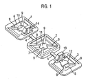
- Figure 1 shows a part consisting of three interconnected segments without any expandable material present to illustrate the structure of the segments.
- Figure 2 shows a four segment part similar to Figure 1 but with the expandable material being present.
- Figure 3 shows a part according to the present invention attached to the interior surface of a hollow section of the A pillar of an automobile prior to foaming of the expandable material.
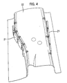
- Figure 4 shows a part according to the present invention attached to the interior surface of a hollow section of the B pillar of an automobile prior to expansion of the expandable material.
- Figure 1 shows a part according to the present invention made by injection moulding of glass filled nylon consisting of three segments (1), (2) and (3) linked by flexible interconnecting members (4) and (5).
- Each segment consists of a rectangular member defining a space (6), (7) and (8) ribs (9) are formed extending into the space defined by the rectangular members, the ribs are integrally moulded with discs (10), (11) and (12).
- the part illustrated in Figure 1 also contains two integrally moulded clips (13) and (14) which can be used to attach the part to the surface of the structure that is to be reinforced. The clips are designed to hold the part away from the surface of the structure.
- Figure 2 shows a four segment part similar to Figure 1 with an additional segment (15).
- the foamable material (16), (17) (18) and (19) present in the spaces provided by the segments.
- Figure 3 shows an unfoamed four segment part (20) similar to the part of Figure 2, mounted within the A pillar (19) of a vehicle and Figure 4 shows two such four segment parts (20) mounted in a front longitudinal section (22) of a vehicle.
- Figure 4 shows how the compact nature of the part enables it to be mounted in a narrow gap in the vehicle structure and it also shows how the flexible nature of the interconnecting elements enables the part to be manoeuvred to match the contoured profile of the vehicle structure.
- the vehicle section with the part of this invention attached thereto may then be assembled into the vehicle body.
- the assembled body may then be subjected to the e coat process and finally baked. Accordingly providing the nature of the foamable material is selected so that it will foam during the baking step it will expand to fill the cavity and provide the desired structural reinforcement and/or acoustic baffle.
- the invention therefore provides a convenient and flexible technique for the provision of structural reinforcement and/or noise abatement in hollow cross sections that are too small for the application of pre-existing techniques or are of variable and/or non-straight cross section.
Abstract
Description
- The present invention relates to materials useful for structural reinforcement of cavities and also as sound reducing baffles. In particular the invention relates to reinforcing materials that can be provided in hollow cross-sectional members to provide reinforcement to improve the structural integrity of vehicles, construction materials, aircraft, ships and railroad applications and/or to produce a sound deadening effect in vehicles, construction materials, aircraft and ships. The invention further provides a system whereby reinforcement and/or a sound deadening effect can be provided whilst ensuring effective provision of an anti-corrosion coating on the inner surface of the hollow cross-sectional member by the electrocoat process used in automobile construction. The electro-coat process is a process in which a metal structure is passed through a bath of anticorrosion fluid and the structure is used as an electrode whereby an anticorrosion coating is deposited from the fluid onto the vehicle structure by electrolysis. The anticorrosion coating is subsequently secured on the structure by baking in an oven.
- The trends in motor vehicle, aircraft, ship and construction material design are towards lighter structures, which with vehicles, aircraft and ships leads to improved fuel consumption. At the same time safety standards and requirements are becoming more rigorous as indicated by the European Union requirements and the Euro-NCAP impact testing. The use of lighter materials such as aluminium to produce the hollow cross-sectional members that are used as vehicle sub frames has lead to the need for additional reinforcement.
- There is a need for reinforcement in various positions in a vehicle structure including the sub frame and upper structure and the form of reinforcement required can vary from one location in the vehicle to another and from vehicle to vehicle. In one aspect the present invention therefore improves the strength of vehicle structures made from existing materials and enhances the safety of vehicle structures based on lighter materials.
- There are four main types of application where structural reinforcement is required in vehicles. Crash protection where the prevention of vehicle body deformation is important to provide protection for the occupants. Energy absorption to enhance performance after yield. The reduction of flexing or body movement in the vehicle structure particular to improve durability and reduce stress cracking and the point mobility problems requiring the reduction of resonance by the provision of stiffening. The need for reinforcement is present irrespective of the materials that are used to produce the vehicle structure and the need varies from material to material according to the nature of the reinforcement that is being provided. There is also a need to reduce the noise created by the motion of vehicles, ships, aircraft and construction materials by providing sound deadening by blocking air paths in cavities. The materials provided by the present invention can therefore provide reinforcement, they can act as acoustic baffles or they can serve both functions.
- It is known to provide longitudinal reinforcing structures within the hollow cross sections of vehicles. For example, PCT Publication WO97/43501 provides a beam, which can be mounted within the cross section to provide reinforcement along one axis in a hollow structure. The beam is provided with an expandable adhesive on two surfaces, which can be foamed upon heating to bond the beam to two opposed walls of the cross section. However, the beam will only provide significant reinforcement along the axis of the beam. In WO97/43501 the beam with foamable material on opposed surfaces is placed in the cavity and subsequently foamed under the action of heat. This will result in uneven foaming and to non-uniform foam structures since on the underside because the foam must raise the weight of the beam whereas expansion on the topside is free.
- It is also known to provide foamable plastic mouldings within the hollow cross sections which can be foamed upon application of heat, such as is provided in the baking oven in the electrocoat process, to provide a foamed baffle that fills the cross-section to provide either structural reinforcement or sound adsorption. Such systems are described in European patent applications 0383498 and 0611778. The foam baffle provides sound deadening and vibration resistance. In these systems the entire insert is foamable and it is proposed that the foamable material be chosen so that it will foam during the baking process, which follows the electrocoat process typically used in vehicle manufacture to provide resistance to metal corrosion. The materials of these patents are primarily used to provide acoustic baffles and seals.
- In the electro-coat process a vehicle structure is immersed in a bath of coating fluid from which an anticorrosion coating is deposited on the metal by electrolysis. The vehicle metal structure is subsequently heated to bake the coating on the metal. The electrocoat process is typically applied to complete vehicle structures in which hollow sections have been capped. Accordingly any reinforcing structures are preferably provided within hollow sections prior to the electrocoat. It is therefore important that the reinforcing structure have minimal impact on the operation and efficiency of the electrocoat process.
- It has also been proposed that structural reinforcement, particularly in vehicles, may be achieved by providing a reinforcing core coated with an expandable adhesive. This structural reinforcement may be appropriately positioned in the hollow vehicle structure. The vehicle structure containing the structural reinforcement with the expandable adhesive in its unexpanded state may then be subjected to the e coat anticorrosion process. The expandable adhesive may then be selected so that it will foam under the conditions in the bake oven of the e coat process to fill the gap between the reinforcing core and the internal surface of the hollow vehicle structure and also for a rigid bond there between.
- The structural reinforcing and/or sound deadening parts that have been provided hitherto are based on a rigid core with a foamable coating thereon. It is therefore difficult with these materials to reinforce sections that contain bends or are of variable cross section. Furthermore, they are generally not suitable for the reinforcement of sections of small cross section such as some of the sections found in the A, B and C pillars of automobiles.
- There is therefore a need to provide structural reinforcement and/or acoustic baffles for the hollow cross-sections of vehicles, which are easily supplied, may be readily used in sections that contain bends or are of narrow and/or variable cross section and which work well within the bounds of the electrocoat process. Where structural reinforcement is to be provided the part must provide effective reinforcement to the vehicle both during vehicle operation and as crash protection.
- The present invention therefore provides a member comprising at least two interconnected segments each segment comprising a support member defining a cavity within the support member and containing a foamable material within said cavity the segments being connected in a manner that enables flexible movement of the segments relative to each other.
- The preferred members comprise at least three and more preferably at least four interconnected segments.
- In a preferred embodiment the cavity within the support member contains ribs which define spaces for and support the foamable material. The ribs also provide additional reinforcement and help to guide the expansion of the foamable material.
- In a further embodiment of the invention the foamable material fills the spaces defined by the ribs.
- In a further embodiment of the invention a small plate, preferably a circular plate is provided in the cavity which supports the foamable material within the cavity. The plate reduces the bending of the ribs during injection of the foamable material. It is also preferred that the plate is integral with the ribs so that the ribs and the plate provide a structure within the cavity which supports and directs the foamable material particularly during foaming when it can be in the form of a low viscosity liquid.
- In a yet further embodiment of the invention the member is provided with clips to enable it to be attached to the surface of the structure. The location of the clips and the number of segments in the reinforcing member will depend upon the nature and shape of the structure to be reinforced. Alternatively, the part may be adhered to the structure or the structure itself may be provided with means for attachment.
- In yet another embodiment of the invention at least part of the internal walls of the support member, which defines the cavity, are provided with an internally facing lip which supports the foamable material and supports and directs the material as it foams. Preferably the lip is provided on all the internal walls.
- The member may also be provided with small lugs, which enable it to stand away from the interior walls of the sections of the vehicle. In this way the fastening devices previously described are not required and the area of contact between the member and the interior walls of the frame of the vehicle is minimised. The clearance between the extremity of the member and the interior walls of the frame of the vehicle is preferably wide enough to enable the liquid used in the electrocoat bath to flow between the member and the interior walls of the sections of the vehicle in sufficient quantity to enable an effective anti-corrosion coating to be deposited. On the other hand, the clearance must not be too wide since this can result in a lack of rigidity in the structure when the expandable adhesive is foamed to fill the clearance and bond the member to the interior walls of the frame of the vehicle. We prefer that the clearance be no more than 1 centimetre and is more preferably 3 to 10 millimetres. A clearance around the whole structure enables a more uniform foam structure to be obtained.
- The invention can be used to provide structural reinforcement and/or sound deadening. The materials from which the member is made will be chosen according to the effect the part is to impart. In a preferred embodiment the invention provides structural reinforcement and it will now be described in relation to that embodiment.
- The reinforcing member may be made from any suitable material, for example it may be made of metal or plastic and the material will be chosen according to the preferred fabrication method. This in turn is driven by economics and the complexity of the cross section to be reinforced. Reinforcing members for simple cross sections may be prepared by extrusion whilst injection moulding may be required for more complex structures. Metal members may be produced by stamping and/or forming. Where extrusion is used the members may be of metal or thermoplastics; where injection moulding is used thermoplastics are preferred. Polyamides, particularly glass filled polyamides are suitable materials due to their high strength to weight ratio. Alternatively injection moulding or die casting of metal alloys may be employed. Injection moulding is particularly preferred because this allows the segments to be moulded together with an integrally moulded, flexible, interconnecting piece to provide the desired degree of flexibility.
- The member of the present invention may be of any thickness, although the invention is most useful in thin and/or narrow cross sections particularly those with bends when it will also be relatively thin. The flexible nature of the links between the segments allows the member to be manipulated to match the contours of the section to be reinforced or the cavity wherein it is desired to provide reinforcement and/or an acoustic baffle. The preferred shape and structure of the member will depend upon where it is to be located in the vehicle structure and the function it is to perform. For example, if it is to be located in the front longitudinal section of the vehicle it will be designed for crash or impact resistance. On the other hand, it may be designed to reduce point mobility such as for example at the base of side and rear pillars. This is particularly important with high-sided vehicles where the reinforcement can reduce or prevent vehicle sway thus reducing metal fatigue. Other applications include the resistance of deformation of the rear longitudinal section, in particular to prevent upward deformation from rear impact, which can prevent the doors from being opened thus trapping the occupants. Parts of the vehicle which may be reinforced by the techniques of the present invention include roof structures, pillars, such as the A pillar, B pillar or C pillar, frame cross members and window frames particularly rear window frames.
- The expandable adhesive material serves two main functions, it will expand to fill the space between the reinforcing member and the interior of the vehicle structure and it will also bond to the interior wall of the structure. Accordingly, expandable adhesive material means that the material can be activated to both expand (typically foam) and to act as an adhesive. Activation therefore enables the expandable material to expand out of the support member of the segment and bridge the gap between the reinforcing member and the hollow structure it is designed to reinforce and also to bond to the internal surface of the hollow structure. Accordingly, in order to provide reinforcement the expandable adhesive must expand at the desired temperature and be sufficiently adhesive to firmly bond the reinforcing member inside the vehicle structure. Once foamed it should be sufficiently strong that it does not contribute any weakness to the overall reinforcing effect provided.
- Prior to activation, the expandable adhesive material is preferably dry and not tacky to the touch, since this facilitates shipping and handling and prevents contamination. Examples of preferred foamable materials for the production of reinforcing materials include foamable epoxy-base resins and examples of such materials are the products L5206, L5207, L5208 and L5209, which are commercially available from L & L Products of Rome Michigan USA, and the Betacore Products BC 5204, 5206, 5205 and 5208 available from Core Products, Strasbourg, France. The product should be chosen according to the rate of expansion and foam densities required. It is further preferred that it expand at the temperatures experienced in the electrocoat baking oven, typically 130°C to 200°C, preferably 130°C to 150°C. If the invention is to be used to provide acoustic baffles the expandable material may be a thermoplastic such as copolymer of ethylene and vinyl acetate or an ethylene acrylate copolymer.
- It is preferred that the reinforcing member is located within the hollow member that it is designed to reinforce in a manner that provides a clearance between the external surface of the member and the internal surface of the hollow member. This allows for the passage of the electrocoat fluid between the member and the internal surface and also enables a uniform expansion of the foam around the member to provide more uniform reinforcement. Accordingly in a preferred process for providing reinforcement within hollow structures such as a vehicle frame, moulded reinforcing members containing the foamable adhesive are installed during assembly of the vehicle frame prior to the frame being subjected to the e coat process.
- Means are preferably provided to position the moulded reinforcing members away from the surface so that the anticorrosion fluid can reach all parts of the surface. These means may be clips or other fastenings which hold the member away from the surface. The clips may be formed on the surfaces or on the moulded reinforcing member itself or both. Alternatively locating lugs may be moulded into the reinforcing member so that the reinforcing member sits within the vehicle structure leaving a space between the member and the interior walls of the cavity to be reinforced, in this way there is no need for fastening or bonding means to attach the member to the interior walls. The assembled structure may then be subjected to the electrocoat process in which it is passed through a bath of coating material and a corrosion resistant coating is deposited onto the structure by electrolysis. The vehicle structure is then dried in an oven to provide the final anticorrosion coating. The expandable adhesive is preferably chosen so that it is activated by the drying conditions used in the oven employed to bake the coating on the electrocoat process. In this way the expandable material will expand under the drying conditions to provide a foam that fills the space between the member and the interior walls to produce a bond between the reinforcing member and the interior wall. Typically the coated structure is dried at around 165°C for about 20 minutes and accordingly the adhesive should expand under these conditions. The industry is however looking to use lower drying temperatures and shorter drying times and this may influence the choice of expandable adhesive materials.
- The techniques of the present invention may be used for the reinforcement of any construction that is based on a hollow frame structure. They may for instance be used in the construction industry, in boats, in aircraft, and in railroad applications.
- They are however particularly useful to provide reinforcement in automobiles including cars, trucks, caravans and the like. The techniques are particularly useful in the current trend towards using lighter and sometimes weaker materials in the production of automobile sub frames where there is a greater need for reinforcement to compensate for the reduction in strength of the basic material and yet satisfy the safety requirements. This is particularly the case with the use of aluminium for the production of automobiles. The invention readily enables reinforcement to be provided in narrow or non-uniform or non-linear hollow sections which has hitherto been difficult to achieve.
- The present invention is illustrated by reference to the accompanying drawings in which Figure 1 shows a part consisting of three interconnected segments without any expandable material present to illustrate the structure of the segments.
- Figure 2 shows a four segment part similar to Figure 1 but with the expandable material being present.
- Figure 3 shows a part according to the present invention attached to the interior surface of a hollow section of the A pillar of an automobile prior to foaming of the expandable material.
- Figure 4 shows a part according to the present invention attached to the interior surface of a hollow section of the B pillar of an automobile prior to expansion of the expandable material.
- Figure 1 shows a part according to the present invention made by injection moulding of glass filled nylon consisting of three segments (1), (2) and (3) linked by flexible interconnecting members (4) and (5). Each segment consists of a rectangular member defining a space (6), (7) and (8) ribs (9) are formed extending into the space defined by the rectangular members, the ribs are integrally moulded with discs (10), (11) and (12). The part illustrated in Figure 1 also contains two integrally moulded clips (13) and (14) which can be used to attach the part to the surface of the structure that is to be reinforced. The clips are designed to hold the part away from the surface of the structure.
- Figure 2 shows a four segment part similar to Figure 1 with an additional segment (15). The foamable material (16), (17) (18) and (19) present in the spaces provided by the segments.
- Figure 3 shows an unfoamed four segment part (20) similar to the part of Figure 2, mounted within the A pillar (19) of a vehicle and Figure 4 shows two such four segment parts (20) mounted in a front longitudinal section (22) of a vehicle. Figure 4 shows how the compact nature of the part enables it to be mounted in a narrow gap in the vehicle structure and it also shows how the flexible nature of the interconnecting elements enables the part to be manoeuvred to match the contoured profile of the vehicle structure.
- The vehicle section with the part of this invention attached thereto may then be assembled into the vehicle body. The assembled body may then be subjected to the e coat process and finally baked. Accordingly providing the nature of the foamable material is selected so that it will foam during the baking step it will expand to fill the cavity and provide the desired structural reinforcement and/or acoustic baffle.
- The invention therefore provides a convenient and flexible technique for the provision of structural reinforcement and/or noise abatement in hollow cross sections that are too small for the application of pre-existing techniques or are of variable and/or non-straight cross section.
Claims (10)
- A member comprising at least two interconnected segments each segment comprising a support member defining a cavity within the support member and containing a foamable material within said cavity the segments being connected in a manner that enables flexible movement of the segments relative to each other.
- A member according to Claim 1, wherein the cavity within the support member contains ribs which define spaces for and support of the foamable material.
- A member according to Claim 2, in which the foamable material fills the spaces defined by the ribs.
- A member according to any of the preceding Claims, in which a small plate is provided in the cavity which supports the foamable material within the cavity.
- A member according to Claim 4, in which the plate is integral with the ribs so that the ribs and the plate provide a structure within the cavity which supports the foamable material and directs the foamable material during foaming.
- A member according to any of the preceding Claims, provided with clips to enable it to be attached to the surface of the structure.
- A member according to any of the preceding Claims in which at least part of the internal walls of the support member, which define the cavity, are provided with an internally facing lip which supports the foamable material and supports and directs the material as it foams.
- A process wherein a reinforcing member according to any of Claims 1 to 7, is located within a hollow structure in a manner that provides a clearance between the external surface of the member and the internal surface of the hollow structure and the structure is then subject to the electrocoat process.
- A process according to Claim 8, in which an assembled structure is passed through a bath of coating material and a coating is deposited onto the surface of the hollow structure, the structure is then dried in an oven to provide the final coating and the foamable material is chosen so that it is activated by the drying conditions used in the oven so that it expands under the oven conditions to provide a foam that fills the space between the member and the interior walls.
- A process according to Claim 9 in which the coating material is a corrosion resistant coating.
Applications Claiming Priority (2)
| Application Number | Priority Date | Filing Date | Title |
|---|---|---|---|
| GBGB0211775.2A GB0211775D0 (en) | 2002-05-23 | 2002-05-23 | Multi segment parts |
| GB0211775 | 2002-05-23 |
Publications (3)
| Publication Number | Publication Date |
|---|---|
| EP1364862A2 true EP1364862A2 (en) | 2003-11-26 |
| EP1364862A3 EP1364862A3 (en) | 2006-03-15 |
| EP1364862B1 EP1364862B1 (en) | 2008-06-25 |
Family
ID=9937191
Family Applications (1)
| Application Number | Title | Priority Date | Filing Date |
|---|---|---|---|
| EP03076320A Expired - Lifetime EP1364862B1 (en) | 2002-05-23 | 2003-04-30 | Multi segment reinforcement parts |
Country Status (9)
| Country | Link |
|---|---|
| US (1) | US7144071B2 (en) |
| EP (1) | EP1364862B1 (en) |
| AT (1) | ATE399118T1 (en) |
| CA (1) | CA2429764A1 (en) |
| DE (1) | DE60321750D1 (en) |
| ES (1) | ES2251890T3 (en) |
| GB (1) | GB0211775D0 (en) |
| MX (1) | MXPA03004541A (en) |
| PT (1) | PT1364862E (en) |
Cited By (8)
| Publication number | Priority date | Publication date | Assignee | Title |
|---|---|---|---|---|
| US6896320B2 (en) | 2002-01-22 | 2005-05-24 | Dow Global Technologies Inc. | Reinforced structural body |
| EP1873021A2 (en) * | 2006-06-20 | 2008-01-02 | Kojima Press Industry Co., Ltd. | Shock absorbing structure for vehicle |
| WO2008059012A1 (en) * | 2006-11-15 | 2008-05-22 | Sika Technology Ag | Baffle assembly |
| FR2988363A1 (en) * | 2012-03-21 | 2013-09-27 | Peugeot Citroen Automobiles Sa | Sealing partition for forming extension in cavity e.g. junction of central foot in structure of vehicle, has set of fixing units attached with cavity and remotely positioned with another set of fixing units with respect to extension |
| EP3037328A1 (en) * | 2008-07-29 | 2016-06-29 | Henkel AG & Co. KGaA | Reinforcement assembly |
| DE102015114238A1 (en) * | 2015-08-27 | 2017-03-02 | Webasto SE | Connection system and method for attaching a component to a vehicle body |
| WO2022221769A1 (en) * | 2021-04-16 | 2022-10-20 | Zephyros, Inc. | Flexible structural reinforcement |
| EP4101739A1 (en) * | 2021-06-11 | 2022-12-14 | Sika Technology AG | Insulating element |
Families Citing this family (39)
| Publication number | Priority date | Publication date | Assignee | Title |
|---|---|---|---|---|
| GB2375328A (en) | 2001-05-08 | 2002-11-13 | L & L Products | Reinforcing element for hollow structural member |
| US7318873B2 (en) | 2002-03-29 | 2008-01-15 | Zephyros, Inc. | Structurally reinforced members |
| CA2482168A1 (en) | 2002-04-15 | 2003-10-30 | Dow Global Technologies Inc. | Improved vehicular structural members and method of making the members |
| US7077460B2 (en) * | 2002-04-30 | 2006-07-18 | L&L Products, Inc. | Reinforcement system utilizing a hollow carrier |
| US20040018353A1 (en) * | 2002-07-25 | 2004-01-29 | L&L Products, Inc. | Composite metal foam damping/reinforcement structure |
| US7313865B2 (en) * | 2003-01-28 | 2008-01-01 | Zephyros, Inc. | Process of forming a baffling, sealing or reinforcement member with thermoset carrier member |
| US7784186B2 (en) | 2003-06-26 | 2010-08-31 | Zephyros, Inc. | Method of forming a fastenable member for sealing, baffling or reinforcing |
| US7249415B2 (en) | 2003-06-26 | 2007-07-31 | Zephyros, Inc. | Method of forming members for sealing or baffling |
| US7469459B2 (en) | 2003-09-18 | 2008-12-30 | Zephyros, Inc. | System and method employing a porous container for sealing, baffling or reinforcing |
| US20050012280A1 (en) * | 2004-08-13 | 2005-01-20 | L&L Products, Inc. | Sealing member, sealing method and system formed therewith |
| JP2006056190A (en) * | 2004-08-23 | 2006-03-02 | Kyowa Sangyo Kk | Hollow chamber shutoff implement for hollow structure |
| US20060043772A1 (en) * | 2004-08-26 | 2006-03-02 | L&L Products, Inc. | Baffle and system formed therewith |
| US7374219B2 (en) | 2004-09-22 | 2008-05-20 | Zephyros, Inc. | Structural reinforcement member and method of use therefor |
| GB0506404D0 (en) * | 2005-03-30 | 2005-05-04 | L & L Products Inc | Improvements in or relating to components |
| US7494179B2 (en) * | 2005-04-26 | 2009-02-24 | Zephyros, Inc. | Member for baffling, reinforcement or sealing |
| US20070080559A1 (en) * | 2005-04-28 | 2007-04-12 | L&L Products, Inc. | Member for baffling, reinforcement of sealing |
| US8381403B2 (en) | 2005-05-25 | 2013-02-26 | Zephyros, Inc. | Baffle for an automotive vehicle and method of use therefor |
| US7597382B2 (en) * | 2005-06-07 | 2009-10-06 | Zephyros, Inc. | Noise reduction member and system |
| US7926179B2 (en) | 2005-08-04 | 2011-04-19 | Zephyros, Inc. | Reinforcements, baffles and seals with malleable carriers |
| US7484946B2 (en) * | 2005-08-19 | 2009-02-03 | Zephyros, Inc. | Method and assembly for locating material within a structure |
| US20070089829A1 (en) * | 2005-10-25 | 2007-04-26 | L&L Products, Inc. | Strength pearls |
| GB0600901D0 (en) | 2006-01-17 | 2006-02-22 | L & L Products Inc | Improvements in or relating to reinforcement of hollow profiles |
| US7913467B2 (en) * | 2006-07-25 | 2011-03-29 | Zephyros, Inc. | Structural reinforcements |
| US7641264B2 (en) | 2007-10-05 | 2010-01-05 | Sika Technology, AG | Reinforcement device |
| US20090096251A1 (en) * | 2007-10-16 | 2009-04-16 | Sika Technology Ag | Securing mechanism |
| US8020924B2 (en) * | 2007-12-26 | 2011-09-20 | Sika Technology Ag | Integrated reinforcing crossmember |
| US8293360B2 (en) * | 2008-02-27 | 2012-10-23 | Sika Technology Ag | Baffle |
| WO2009124177A1 (en) * | 2008-04-04 | 2009-10-08 | Sika Technology Ag | Expandable barrier |
| US8133929B2 (en) * | 2008-04-15 | 2012-03-13 | Sika Technology Ag | Method for incorporating long glass fibers into epoxy-based reinforcing resins |
| ES2376951T3 (en) * | 2008-08-05 | 2012-03-21 | Sika Technology Ag | screen |
| NO331928B1 (en) * | 2010-03-31 | 2012-05-07 | Aker Engineering & Technology | Extruded elements |
| US8545956B2 (en) | 2010-04-26 | 2013-10-01 | Sika Technology Ag | Expandable insert with flexible substrate |
| US20140035309A1 (en) * | 2012-08-02 | 2014-02-06 | Toyota Motor Engineering & Manufacturing North America, Inc. | Vehicle body expansion foam |
| US9701093B2 (en) | 2013-04-30 | 2017-07-11 | Zephyros, Inc. | Surface conforming activatable adhesive bodies and methods of making same |
| DE102014218730A1 (en) | 2014-09-18 | 2016-03-24 | Ford Global Technologies, Llc | Energy absorber and overhead system with energy absorber |
| US9764769B2 (en) | 2015-02-09 | 2017-09-19 | Honda Motor Co., Ltd. | Vehicle frame structural member assembly and method |
| EP3294547A1 (en) | 2015-05-14 | 2018-03-21 | Zephyros Inc. | Localized panel stiffener |
| CN109154386A (en) * | 2016-03-16 | 2019-01-04 | 泽菲罗斯有限公司 | For sealing, the flexible member of barrier or reinforcing |
| US10829159B2 (en) * | 2018-09-18 | 2020-11-10 | Fca Us Llc | Vehicle having reinforcement assemblies |
Citations (4)
| Publication number | Priority date | Publication date | Assignee | Title |
|---|---|---|---|---|
| US5506025A (en) * | 1995-01-09 | 1996-04-09 | Sika Corporation | Expandable baffle apparatus |
| US6114004A (en) * | 1998-01-26 | 2000-09-05 | Cydzik; Edward A. | Cavity sealing article |
| US6250711B1 (en) * | 1998-07-31 | 2001-06-26 | Toyota Jidosha Kabushiki Kaisha | Energy absorber securing structure and method |
| US20020033617A1 (en) * | 2000-09-15 | 2002-03-21 | Blank Norman E. | Side impact reinforcement |
Family Cites Families (145)
| Publication number | Priority date | Publication date | Assignee | Title |
|---|---|---|---|---|
| US2204622A (en) * | 1936-03-27 | 1940-06-18 | Rubatex Products Inc | Method of manufacturing windlace cord |
| US2156681A (en) * | 1936-06-18 | 1939-05-02 | Goodrich Co B F | Sealing strip |
| US2230688A (en) * | 1939-03-09 | 1941-02-04 | Goodrich Co B F | Expansion joint |
| US3258890A (en) * | 1962-05-28 | 1966-07-05 | Dow Chemical Co | Framed wall construction with blowout panel |
| US3400182A (en) | 1965-08-03 | 1968-09-03 | Budd Co | Method of interconnecting spaced panels and means for use therein |
| US3378958A (en) * | 1966-09-21 | 1968-04-23 | Goodrich Co B F | Extrusions having integral portions of different stiffness |
| AT292275B (en) | 1967-07-06 | 1971-08-25 | Graeff Roderich Wilhelm | Large-area plate-shaped component made of thermosetting plastics |
| US3923411A (en) * | 1975-01-28 | 1975-12-02 | Thor Johan Berghman | Sealing strip |
| BR7603818A (en) * | 1976-06-14 | 1978-01-03 | P Betti | SEALING ELEMENT, FOR JOINT COMPOSITION, SPECIALLY INTENDED FOR CIVIL CONSTRUCTION |
| JPS6056114B2 (en) * | 1981-03-16 | 1985-12-09 | 日産自動車株式会社 | Reinforcement material for reinforcing plate materials |
| US4610907A (en) * | 1983-05-05 | 1986-09-09 | Elastomeros Riojanos S.A. | Metal core of sections for automobile and similar vehicles |
| US4610836A (en) | 1983-09-12 | 1986-09-09 | General Motors Corporation | Method of reinforcing a structural member |
| US4463870A (en) | 1983-10-19 | 1984-08-07 | L & L Products, Inc. | Closure plate for an opening |
| DE3345576A1 (en) | 1983-12-16 | 1985-06-27 | Ford-Werke AG, 5000 Köln | SANDWICH COMPONENT, IN PARTICULAR HOOD, FLAP OR THE LIKE FOR A MOTOR VEHICLE BODY |
| DE3423827A1 (en) | 1984-06-04 | 1985-02-14 | Stübbe GmbH, 2940 Wilhemshaven | PLASTIC DOOR FOR MOTOR VEHICLES |
| GB8425914D0 (en) * | 1984-10-13 | 1984-11-21 | Wilson Eng Ltd F G | Roofs for vehicles |
| US4769391A (en) | 1985-12-19 | 1988-09-06 | Essex Composite Systems | Reinforcement insert for a structural member and method of making and using the same |
| US4751249A (en) * | 1985-12-19 | 1988-06-14 | Mpa Diversified Products Inc. | Reinforcement insert for a structural member and method of making and using the same |
| US4783931A (en) * | 1986-04-07 | 1988-11-15 | Bridgestone Australia Ltd. | Glass run channel |
| DE3637751A1 (en) * | 1986-11-05 | 1988-05-11 | Bayer Ag | PLASTIC SHOCK ABSORBER WITH BUMPER |
| US4861097A (en) | 1987-09-18 | 1989-08-29 | Essex Composite Systems | Lightweight composite automotive door beam and method of manufacturing same |
| US4813690A (en) * | 1987-11-24 | 1989-03-21 | L & L Products, Inc. | Sealing member |
| GB8800773D0 (en) * | 1988-01-14 | 1988-02-17 | Friesen P | Building panel |
| US4923902A (en) * | 1988-03-10 | 1990-05-08 | Essex Composite Systems | Process and compositions for reinforcing structural members |
| CA1299032C (en) * | 1988-03-30 | 1992-04-21 | Herman E. Turner, Jr. | Closed cell foam seals for automotive body seams, method and apparatus for making same |
| US4836516A (en) * | 1988-04-25 | 1989-06-06 | Essex Composite Systems | Filled tubular torsion bar and its method of manufacture |
| US4853270A (en) | 1988-06-27 | 1989-08-01 | Essex Specialty Products, Inc. | Knee blocker for automotive application |
| US4810548A (en) * | 1988-08-01 | 1989-03-07 | Ligon Brothers Manufacturing Company | Sandwich seal fixture |
| US4979846A (en) * | 1988-11-16 | 1990-12-25 | Ronald A. Hill | Contraction joint for concrete linings |
| FR2651728B1 (en) * | 1989-09-13 | 1993-11-12 | Hutchinson | METAL REINFORCEMENT FOR STRIP OR SEAL FOR USE, PARTICULARLY, IN THE AUTOMOTIVE INDUSTRY. |
| US4996090A (en) * | 1989-11-20 | 1991-02-26 | Process Bonding, Inc. | Door panel |
| US4978562A (en) | 1990-02-05 | 1990-12-18 | Mpa Diversified Products, Inc. | Composite tubular door beam reinforced with a syntactic foam core localized at the mid-span of the tube |
| US5124186A (en) * | 1990-02-05 | 1992-06-23 | Mpa Diversified Products Co. | Composite tubular door beam reinforced with a reacted core localized at the mid-span of the tube |
| US5288538A (en) * | 1992-12-16 | 1994-02-22 | Reynolds Metals Company | Expandable honeycomb core structural member |
| US5358397A (en) | 1993-05-10 | 1994-10-25 | L&L Products, Inc. | Apparatus for extruding flowable materials |
| US5531455A (en) * | 1993-09-16 | 1996-07-02 | Calixto; Jorge Gabrielli Z. | Expansion joint sealing element |
| EP0679501A1 (en) * | 1994-03-14 | 1995-11-02 | YMOS AKTIENGESELLSCHAFT Industrieprodukte | Composite material with foamable core |
| US6168226B1 (en) * | 1994-05-19 | 2001-01-02 | Henkel Corporation | Composite laminate automotive structures |
| JP2721327B2 (en) | 1995-02-09 | 1998-03-04 | 株式会社ネオックスラボ | Support structure of foamable material in hollow structure |
| US5642914A (en) | 1995-03-24 | 1997-07-01 | Neo-Ex Lab. Inc. | Support structure for supporting foamable material on hollow structural member |
| US6165588A (en) | 1998-09-02 | 2000-12-26 | Henkel Corporation | Reinforcement of hollow sections using extrusions and a polymer binding layer |
| US5755486A (en) * | 1995-05-23 | 1998-05-26 | Novamax Technologies Holdings, Inc. | Composite structural reinforcement member |
| JP3501879B2 (en) * | 1995-07-31 | 2004-03-02 | 株式会社ネオックスラボ | Support structure of foamable material in hollow structure |
| DE19528825A1 (en) | 1995-08-05 | 1997-02-06 | Sika Ag | Soundproofing partition |
| US20020066254A1 (en) * | 1995-09-04 | 2002-06-06 | Alfred Ebbinghaus | Reinforced formed part, process for its production and its use |
| US5985435A (en) | 1996-01-23 | 1999-11-16 | L & L Products, Inc. | Magnetized hot melt adhesive articles |
| US6059342A (en) * | 1996-02-19 | 2000-05-09 | Nissan Motor Co., Ltd. | Car body structure |
| US6141930A (en) * | 1996-04-16 | 2000-11-07 | Johns Manville International, Inc. | Method of and article for insulating standard and nonstandard cavities and an insulated structure |
| US6341467B1 (en) * | 1996-05-10 | 2002-01-29 | Henkel Corporation | Internal reinforcement for hollow structural elements |
| US5888600A (en) * | 1996-07-03 | 1999-03-30 | Henkel Corporation | Reinforced channel-shaped structural member |
| US6482496B1 (en) | 1996-07-03 | 2002-11-19 | Henkel Corporation | Foil backed laminate reinforcement |
| US6270600B1 (en) | 1996-07-03 | 2001-08-07 | Henkel Corporation | Reinforced channel-shaped structural member methods |
| US5819408A (en) | 1996-07-10 | 1998-10-13 | Xcorp, Inc. | Recyclable, low cost, collision-resistant automobile chassis and body |
| DE19707136C2 (en) | 1997-02-22 | 2001-03-08 | Moeller Plast Gmbh | Process and foamable mass for the foaming or foam coating of components |
| CA2198310C (en) * | 1997-02-24 | 2001-10-30 | David Johnston | Pre-stressed built-up insulated construction panel |
| US5904024A (en) * | 1997-02-26 | 1999-05-18 | Axxis Corp. | Mount construction of foam substrate in hollow structures |
| US5851626A (en) * | 1997-04-22 | 1998-12-22 | Lear Corporation | Vehicle acoustic damping and decoupling system |
| US6099948A (en) | 1997-05-08 | 2000-08-08 | Henkel Corporation | Encapsulation of pre-expanded elastomeric foam with a thermoplastic |
| US6237304B1 (en) * | 1997-07-18 | 2001-05-29 | Henkel Corporation | Laminate structural bulkhead |
| US6233826B1 (en) * | 1997-07-21 | 2001-05-22 | Henkel Corp | Method for reinforcing structural members |
| US6096403A (en) | 1997-07-21 | 2000-08-01 | Henkel Corporation | Reinforced structural members |
| DE19736839A1 (en) | 1997-08-23 | 1999-02-25 | Volkswagen Ag | Deformation structure for occupant protection in vehicles |
| ATE206794T1 (en) * | 1997-08-26 | 2001-10-15 | Stresshead Ag | REINFORCEMENT DEVICE FOR SUPPORT STRUCTURES |
| DE19753318A1 (en) * | 1997-12-02 | 1999-06-10 | Sika Ag | Reinforcing element for load-bearing or load-transmitting components and method for fastening it to a component surface |
| US6103341A (en) | 1997-12-08 | 2000-08-15 | L&L Products | Self-sealing partition |
| US6079160A (en) * | 1998-01-13 | 2000-06-27 | Arrowhead Industries Corporation | Core metal insert with stagger and offset backbone |
| US6068424A (en) * | 1998-02-04 | 2000-05-30 | Henkel Corporation | Three dimensional composite joint reinforcement for an automotive vehicle |
| US6003274A (en) | 1998-02-13 | 1999-12-21 | Henkel Corporation | Lightweight laminate reinforcing web |
| US6372334B1 (en) * | 1998-03-30 | 2002-04-16 | Henkel Corporation | Reinforcement laminate |
| US6079180A (en) * | 1998-05-22 | 2000-06-27 | Henkel Corporation | Laminate bulkhead with flared edges |
| US5992923A (en) | 1998-05-27 | 1999-11-30 | Henkel Corporation | Reinforced beam assembly |
| US6267436B1 (en) | 1998-07-22 | 2001-07-31 | Toyota Jidosha Kabushiki Kaisha | Impact energy absorbing structure in upper vehicle body portion, and impact energy absorbing component |
| US6247287B1 (en) * | 1998-08-05 | 2001-06-19 | Neo-Ex Lab, Inc. | Structure and method for closing and reinforcing hollow structural members |
| US6272809B1 (en) | 1998-09-09 | 2001-08-14 | Henkel Corporation | Three dimensional laminate beam structure |
| US6033300A (en) * | 1998-10-21 | 2000-03-07 | L & L Products, Inc. | Automotive vehicle HVAC rainhat |
| US6387470B1 (en) * | 1998-11-05 | 2002-05-14 | Sika Corporation | Sound deadening and structural reinforcement compositions and methods of using the same |
| JP3386730B2 (en) * | 1998-11-30 | 2003-03-17 | 株式会社ネオックスラボ | Isolation and reinforcement tools for hollow structures |
| US6276105B1 (en) | 1999-01-11 | 2001-08-21 | Henkel Corporation | Laminate reinforced beam with tapered polymer layer |
| US6189953B1 (en) * | 1999-01-25 | 2001-02-20 | Henkel Corporation | Reinforced structural assembly |
| US6149227A (en) | 1999-01-25 | 2000-11-21 | Henkel Corporation | Reinforced structural assembly |
| US6092864A (en) | 1999-01-25 | 2000-07-25 | Henkel Corporation | Oven cured structural foam with designed-in sag positioning |
| DE19909270A1 (en) * | 1999-03-03 | 2000-09-07 | Henkel Teroson Gmbh | Thermosetting, thermally expandable molded body |
| US6131897A (en) | 1999-03-16 | 2000-10-17 | L & L Products, Inc. | Structural reinforcements |
| US6150428A (en) | 1999-09-28 | 2000-11-21 | Sika Corporation | Expansion temperature tolerant dry expandable sealant and baffle product and method of preparing same |
| US6358584B1 (en) * | 1999-10-27 | 2002-03-19 | L&L Products | Tube reinforcement with deflecting wings and structural foam |
| USH2047H1 (en) | 1999-11-10 | 2002-09-03 | Henkel Corporation | Reinforcement laminate |
| US6263635B1 (en) | 1999-12-10 | 2001-07-24 | L&L Products, Inc. | Tube reinforcement having displaceable modular components |
| US6668457B1 (en) * | 1999-12-10 | 2003-12-30 | L&L Products, Inc. | Heat-activated structural foam reinforced hydroform |
| US6199940B1 (en) * | 2000-01-31 | 2001-03-13 | Sika Corporation | Tubular structural reinforcing member with thermally expansible foaming material |
| MXPA02007372A (en) * | 2000-01-31 | 2003-02-12 | Sika Corp | Structural reinforcing member with ribbed thermally expansible foaming material. |
| US6305136B1 (en) | 2000-01-31 | 2001-10-23 | Sika Corporation | Reinforcing member with beam shaped carrier and thermally expansible reinforcing material |
| US6253524B1 (en) | 2000-01-31 | 2001-07-03 | Sika Corporation | Reinforcing member with thermally expansible structural reinforcing material and directional shelf |
| US6475577B1 (en) | 2000-02-07 | 2002-11-05 | Sika Corporation | Reinforcing member with intersecting support legs |
| US6467834B1 (en) | 2000-02-11 | 2002-10-22 | L&L Products | Structural reinforcement system for automotive vehicles |
| US6296298B1 (en) | 2000-03-14 | 2001-10-02 | L&L Products, Inc. | Structural reinforcement member for wheel well |
| US6422575B1 (en) * | 2000-03-14 | 2002-07-23 | L&L Products, Inc. | Expandable pre-formed plug |
| US6482486B1 (en) | 2000-03-14 | 2002-11-19 | L&L Products | Heat activated reinforcing sleeve |
| US6382635B1 (en) * | 2000-03-17 | 2002-05-07 | Sika Corporation | Double walled baffle |
| US6413611B1 (en) | 2000-05-01 | 2002-07-02 | Sika Corporation | Baffle and reinforcement assembly |
| US6196621B1 (en) * | 2000-05-24 | 2001-03-06 | Daimlerchrysler Corporation | Apparatus for transferring impact energy from a tire and wheel assembly of a motor vehicle to a sill |
| US6321793B1 (en) | 2000-06-12 | 2001-11-27 | L&L Products | Bladder system for reinforcing a portion of a longitudinal structure |
| US6319964B1 (en) | 2000-06-30 | 2001-11-20 | Sika Corporation | Acoustic baffle with predetermined directional expansion characteristics |
| US6523857B1 (en) * | 2000-07-05 | 2003-02-25 | Sika Corporation | Reinforcing member for interfitting channels |
| US6820923B1 (en) * | 2000-08-03 | 2004-11-23 | L&L Products | Sound absorption system for automotive vehicles |
| US6634698B2 (en) * | 2000-08-14 | 2003-10-21 | L&L Products, Inc. | Vibrational reduction system for automotive vehicles |
| DE10039720A1 (en) * | 2000-08-14 | 2002-02-28 | Hilti Ag | Fire protection sleeve |
| US6419305B1 (en) | 2000-09-29 | 2002-07-16 | L&L Products, Inc. | Automotive pillar reinforcement system |
| US6561571B1 (en) * | 2000-09-29 | 2003-05-13 | L&L Products, Inc. | Structurally enhanced attachment of a reinforcing member |
| US6471285B1 (en) * | 2000-09-29 | 2002-10-29 | L&L Products, Inc. | Hydroform structural reinforcement system |
| US6455146B1 (en) | 2000-10-31 | 2002-09-24 | Sika Corporation | Expansible synthetic resin baffle with magnetic attachment |
| US6684574B2 (en) * | 2000-10-31 | 2004-02-03 | Toyoda Gosei Co., Ltd. | Insert for trim, trim and weather strip for vehicle |
| JP2002166804A (en) * | 2000-12-01 | 2002-06-11 | Kojima Press Co Ltd | Vehicular impact absorbing structure body and impact absorbing structure of vehicular interior parts using the same |
| USD457120S1 (en) * | 2001-01-08 | 2002-05-14 | Sika Corporation | Ribbed structural reinforcing member |
| US6546693B2 (en) * | 2001-04-11 | 2003-04-15 | Henkel Corporation | Reinforced structural assembly |
| US6502821B2 (en) * | 2001-05-16 | 2003-01-07 | L&L Products, Inc. | Automotive body panel damping system |
| US20030001469A1 (en) * | 2001-06-06 | 2003-01-02 | L&L Products, Inc. | Structural reinforcement and method of use therefor |
| US6855652B2 (en) * | 2001-08-24 | 2005-02-15 | L&L Products, Inc. | Structurally reinforced panels |
| US20030050352A1 (en) * | 2001-09-04 | 2003-03-13 | Symyx Technologies, Inc. | Foamed Polymer System employing blowing agent performance enhancer |
| US6729425B2 (en) * | 2001-09-05 | 2004-05-04 | L&L Products, Inc. | Adjustable reinforced structural assembly and method of use therefor |
| US6887914B2 (en) * | 2001-09-07 | 2005-05-03 | L&L Products, Inc. | Structural hot melt material and methods |
| US6786533B2 (en) * | 2001-09-24 | 2004-09-07 | L&L Products, Inc. | Structural reinforcement system having modular segmented characteristics |
| US6793274B2 (en) * | 2001-11-14 | 2004-09-21 | L&L Products, Inc. | Automotive rail/frame energy management system |
| GB0211287D0 (en) * | 2002-05-17 | 2002-06-26 | L & L Products Inc | Improved baffle precursors |
| US20040011282A1 (en) * | 2002-07-18 | 2004-01-22 | Myers Robert D. | System and method for manufacturing physical barriers |
| US20040018353A1 (en) * | 2002-07-25 | 2004-01-29 | L&L Products, Inc. | Composite metal foam damping/reinforcement structure |
| US7004536B2 (en) * | 2002-07-29 | 2006-02-28 | L&L Products, Inc. | Attachment system and method of forming same |
| US20040034982A1 (en) * | 2002-07-30 | 2004-02-26 | L&L Products, Inc. | System and method for sealing, baffling or reinforcing |
| US20040076831A1 (en) * | 2002-10-02 | 2004-04-22 | L&L Products, Inc. | Synthetic material and methods of forming and applying same |
| JP3967647B2 (en) * | 2002-08-28 | 2007-08-29 | 小島プレス工業株式会社 | Shock absorbing structure for vehicle |
| US20040056472A1 (en) * | 2002-09-25 | 2004-03-25 | L&L Products, Inc. | Fuel fill assembly and method of forming same |
| GB0300159D0 (en) * | 2003-01-06 | 2003-02-05 | L & L Products Inc | Improved reinforcing members |
| US7041193B2 (en) * | 2003-05-14 | 2006-05-09 | L & L Products, Inc. | Method of adhering members and an assembly formed thereby |
| US6955593B2 (en) * | 2003-06-03 | 2005-10-18 | L & L Products, Inc. | HVAC protection system for automotive vehicles |
| US20050016807A1 (en) * | 2003-07-21 | 2005-01-27 | L&L Products, Inc. | Crash box |
| JP4467040B2 (en) * | 2003-09-12 | 2010-05-26 | 本田技研工業株式会社 | Filling structure |
| US20050087899A1 (en) * | 2003-10-22 | 2005-04-28 | L&L Products, Inc. | Baffle and method of forming same |
| US20050126286A1 (en) * | 2003-12-10 | 2005-06-16 | L&L Products, Inc. | Method for balancing a movable member and member formed thereby |
| US8070994B2 (en) * | 2004-06-18 | 2011-12-06 | Zephyros, Inc. | Panel structure |
| GB2415658A (en) * | 2004-06-21 | 2006-01-04 | L & L Products Inc | An overmoulding process |
| US7521093B2 (en) * | 2004-07-21 | 2009-04-21 | Zephyros, Inc. | Method of sealing an interface |
| US20060021697A1 (en) * | 2004-07-30 | 2006-02-02 | L&L Products, Inc. | Member for reinforcing, sealing or baffling and reinforcement system formed therewith |
| US20050012280A1 (en) * | 2004-08-13 | 2005-01-20 | L&L Products, Inc. | Sealing member, sealing method and system formed therewith |
| US20060043772A1 (en) * | 2004-08-26 | 2006-03-02 | L&L Products, Inc. | Baffle and system formed therewith |
| US7374219B2 (en) * | 2004-09-22 | 2008-05-20 | Zephyros, Inc. | Structural reinforcement member and method of use therefor |
| US20060065483A1 (en) * | 2004-09-29 | 2006-03-30 | L&L Products, Inc. | Baffle with flow-through medium |
-
2002
- 2002-05-23 GB GBGB0211775.2A patent/GB0211775D0/en not_active Ceased
-
2003
- 2003-04-30 AT AT03076320T patent/ATE399118T1/en not_active IP Right Cessation
- 2003-04-30 DE DE60321750T patent/DE60321750D1/en not_active Expired - Lifetime
- 2003-04-30 PT PT03076320T patent/PT1364862E/en unknown
- 2003-04-30 ES ES03076320T patent/ES2251890T3/en not_active Expired - Lifetime
- 2003-04-30 EP EP03076320A patent/EP1364862B1/en not_active Expired - Lifetime
- 2003-05-06 US US10/430,964 patent/US7144071B2/en active Active
- 2003-05-22 MX MXPA03004541A patent/MXPA03004541A/en unknown
- 2003-05-23 CA CA002429764A patent/CA2429764A1/en not_active Abandoned
Patent Citations (4)
| Publication number | Priority date | Publication date | Assignee | Title |
|---|---|---|---|---|
| US5506025A (en) * | 1995-01-09 | 1996-04-09 | Sika Corporation | Expandable baffle apparatus |
| US6114004A (en) * | 1998-01-26 | 2000-09-05 | Cydzik; Edward A. | Cavity sealing article |
| US6250711B1 (en) * | 1998-07-31 | 2001-06-26 | Toyota Jidosha Kabushiki Kaisha | Energy absorber securing structure and method |
| US20020033617A1 (en) * | 2000-09-15 | 2002-03-21 | Blank Norman E. | Side impact reinforcement |
Cited By (13)
| Publication number | Priority date | Publication date | Assignee | Title |
|---|---|---|---|---|
| US6896320B2 (en) | 2002-01-22 | 2005-05-24 | Dow Global Technologies Inc. | Reinforced structural body |
| EP1873021A2 (en) * | 2006-06-20 | 2008-01-02 | Kojima Press Industry Co., Ltd. | Shock absorbing structure for vehicle |
| EP1873021A3 (en) * | 2006-06-20 | 2009-07-01 | Kojima Press Industry Co., Ltd. | Shock absorbing structure for vehicle |
| WO2008059012A1 (en) * | 2006-11-15 | 2008-05-22 | Sika Technology Ag | Baffle assembly |
| US7841647B2 (en) | 2006-11-15 | 2010-11-30 | Sika Technology Ag | Baffle assembly |
| CN101568464B (en) * | 2006-11-15 | 2011-05-04 | Sika技术股份公司 | Baffle assembly |
| EP3037328A1 (en) * | 2008-07-29 | 2016-06-29 | Henkel AG & Co. KGaA | Reinforcement assembly |
| FR2988363A1 (en) * | 2012-03-21 | 2013-09-27 | Peugeot Citroen Automobiles Sa | Sealing partition for forming extension in cavity e.g. junction of central foot in structure of vehicle, has set of fixing units attached with cavity and remotely positioned with another set of fixing units with respect to extension |
| DE102015114238A1 (en) * | 2015-08-27 | 2017-03-02 | Webasto SE | Connection system and method for attaching a component to a vehicle body |
| DE102015114238B4 (en) | 2015-08-27 | 2022-03-24 | Webasto SE | Attachment system and method for attaching a component to a vehicle body |
| WO2022221769A1 (en) * | 2021-04-16 | 2022-10-20 | Zephyros, Inc. | Flexible structural reinforcement |
| EP4101739A1 (en) * | 2021-06-11 | 2022-12-14 | Sika Technology AG | Insulating element |
| WO2022258786A1 (en) * | 2021-06-11 | 2022-12-15 | Sika Technology Ag | Insulating element |
Also Published As
| Publication number | Publication date |
|---|---|
| ES2251890T3 (en) | 2008-12-01 |
| EP1364862A3 (en) | 2006-03-15 |
| US7144071B2 (en) | 2006-12-05 |
| MXPA03004541A (en) | 2004-10-29 |
| ATE399118T1 (en) | 2008-07-15 |
| ES2251890T1 (en) | 2006-05-16 |
| PT1364862E (en) | 2008-07-31 |
| GB0211775D0 (en) | 2002-07-03 |
| CA2429764A1 (en) | 2003-11-23 |
| DE60321750D1 (en) | 2008-08-07 |
| EP1364862B1 (en) | 2008-06-25 |
| US20030218019A1 (en) | 2003-11-27 |
Similar Documents
| Publication | Publication Date | Title |
|---|---|---|
| EP1364862B1 (en) | Multi segment reinforcement parts | |
| EP1373055B1 (en) | Structural foam | |
| EP1435320B1 (en) | Reinforcing members for hollow profiles | |
| US7255388B2 (en) | Reinforcing members | |
| EP1387789B1 (en) | Improved structural reinforcement | |
| US7479246B2 (en) | Overmoulding | |
| EP1979221B1 (en) | Improvements in or relating to reinforcement of hollow profiles | |
| EP1607204A2 (en) | Manufacture of laminar mouldings | |
| WO2006066966A1 (en) | Improvements in or relating to the structural reinforcement of vehicles |
Legal Events
| Date | Code | Title | Description |
|---|---|---|---|
| PUAI | Public reference made under article 153(3) epc to a published international application that has entered the european phase |
Free format text: ORIGINAL CODE: 0009012 |
|
| AK | Designated contracting states |
Kind code of ref document: A2 Designated state(s): AT BE BG CH CY CZ DE DK EE ES FI FR GB GR HU IE IT LI LU MC NL PT RO SE SI SK TR |
|
| AX | Request for extension of the european patent |
Extension state: AL LT LV MK |
|
| PUAL | Search report despatched |
Free format text: ORIGINAL CODE: 0009013 |
|
| AK | Designated contracting states |
Kind code of ref document: A3 Designated state(s): AT BE BG CH CY CZ DE DK EE ES FI FR GB GR HU IE IT LI LU MC NL PT RO SE SI SK TR |
|
| AX | Request for extension of the european patent |
Extension state: AL LT LV MK |
|
| 17P | Request for examination filed |
Effective date: 20060913 |
|
| AKX | Designation fees paid |
Designated state(s): AT BE BG CH CY CZ DE DK EE ES FI FR GB GR HU IE IT LI LU MC NL PT RO SE SI SK TR |
|
| 17Q | First examination report despatched |
Effective date: 20070219 |
|
| GRAP | Despatch of communication of intention to grant a patent |
Free format text: ORIGINAL CODE: EPIDOSNIGR1 |
|
| RIN1 | Information on inventor provided before grant (corrected) |
Inventor name: BIEBER, SERGE Inventor name: SOUVAY, DENIS Inventor name: LE GALL, ERIC Inventor name: LUTZ, JEAN-PHILIPPE |
|
| RAP1 | Party data changed (applicant data changed or rights of an application transferred) |
Owner name: ZEPHYROS INC. |
|
| GRAS | Grant fee paid |
Free format text: ORIGINAL CODE: EPIDOSNIGR3 |
|
| GRAA | (expected) grant |
Free format text: ORIGINAL CODE: 0009210 |
|
| AK | Designated contracting states |
Kind code of ref document: B1 Designated state(s): AT BE BG CH CY CZ DE DK EE ES FI FR GB GR HU IE IT LI LU MC NL PT RO SE SI SK TR |
|
| REG | Reference to a national code |
Ref country code: GB Ref legal event code: FG4D |
|
| REG | Reference to a national code |
Ref country code: PT Ref legal event code: SC4A Free format text: AVAILABILITY OF NATIONAL TRANSLATION Effective date: 20080721 Ref country code: CH Ref legal event code: EP |
|
| REF | Corresponds to: |
Ref document number: 60321750 Country of ref document: DE Date of ref document: 20080807 Kind code of ref document: P |
|
| REG | Reference to a national code |
Ref country code: IE Ref legal event code: FG4D |
|
| REG | Reference to a national code |
Ref country code: SE Ref legal event code: TRGR |
|
| PG25 | Lapsed in a contracting state [announced via postgrant information from national office to epo] |
Ref country code: SI Free format text: LAPSE BECAUSE OF FAILURE TO SUBMIT A TRANSLATION OF THE DESCRIPTION OR TO PAY THE FEE WITHIN THE PRESCRIBED TIME-LIMIT Effective date: 20080625 Ref country code: FI Free format text: LAPSE BECAUSE OF FAILURE TO SUBMIT A TRANSLATION OF THE DESCRIPTION OR TO PAY THE FEE WITHIN THE PRESCRIBED TIME-LIMIT Effective date: 20080625 |
|
| PG25 | Lapsed in a contracting state [announced via postgrant information from national office to epo] |
Ref country code: NL Free format text: LAPSE BECAUSE OF FAILURE TO SUBMIT A TRANSLATION OF THE DESCRIPTION OR TO PAY THE FEE WITHIN THE PRESCRIBED TIME-LIMIT Effective date: 20080625 Ref country code: AT Free format text: LAPSE BECAUSE OF FAILURE TO SUBMIT A TRANSLATION OF THE DESCRIPTION OR TO PAY THE FEE WITHIN THE PRESCRIBED TIME-LIMIT Effective date: 20080625 |
|
| REG | Reference to a national code |
Ref country code: ES Ref legal event code: FG2A Ref document number: 2251890 Country of ref document: ES Kind code of ref document: T3 |
|
| NLV1 | Nl: lapsed or annulled due to failure to fulfill the requirements of art. 29p and 29m of the patents act | ||
| PG25 | Lapsed in a contracting state [announced via postgrant information from national office to epo] |
Ref country code: BE Free format text: LAPSE BECAUSE OF FAILURE TO SUBMIT A TRANSLATION OF THE DESCRIPTION OR TO PAY THE FEE WITHIN THE PRESCRIBED TIME-LIMIT Effective date: 20080625 Ref country code: RO Free format text: LAPSE BECAUSE OF FAILURE TO SUBMIT A TRANSLATION OF THE DESCRIPTION OR TO PAY THE FEE WITHIN THE PRESCRIBED TIME-LIMIT Effective date: 20080625 |
|
| PG25 | Lapsed in a contracting state [announced via postgrant information from national office to epo] |
Ref country code: EE Free format text: LAPSE BECAUSE OF FAILURE TO SUBMIT A TRANSLATION OF THE DESCRIPTION OR TO PAY THE FEE WITHIN THE PRESCRIBED TIME-LIMIT Effective date: 20080625 Ref country code: BG Free format text: LAPSE BECAUSE OF FAILURE TO SUBMIT A TRANSLATION OF THE DESCRIPTION OR TO PAY THE FEE WITHIN THE PRESCRIBED TIME-LIMIT Effective date: 20080925 Ref country code: DK Free format text: LAPSE BECAUSE OF FAILURE TO SUBMIT A TRANSLATION OF THE DESCRIPTION OR TO PAY THE FEE WITHIN THE PRESCRIBED TIME-LIMIT Effective date: 20080625 |
|
| PLBE | No opposition filed within time limit |
Free format text: ORIGINAL CODE: 0009261 |
|
| STAA | Information on the status of an ep patent application or granted ep patent |
Free format text: STATUS: NO OPPOSITION FILED WITHIN TIME LIMIT |
|
| PGFP | Annual fee paid to national office [announced via postgrant information from national office to epo] |
Ref country code: CZ Payment date: 20090323 Year of fee payment: 7 Ref country code: SK Payment date: 20090325 Year of fee payment: 7 |
|
| 26N | No opposition filed |
Effective date: 20090326 |
|
| PGFP | Annual fee paid to national office [announced via postgrant information from national office to epo] |
Ref country code: PT Payment date: 20090408 Year of fee payment: 7 Ref country code: SE Payment date: 20090416 Year of fee payment: 7 |
|
| PGFP | Annual fee paid to national office [announced via postgrant information from national office to epo] |
Ref country code: CH Payment date: 20090417 Year of fee payment: 7 |
|
| PGFP | Annual fee paid to national office [announced via postgrant information from national office to epo] |
Ref country code: GB Payment date: 20090421 Year of fee payment: 7 |
|
| PG25 | Lapsed in a contracting state [announced via postgrant information from national office to epo] |
Ref country code: MC Free format text: LAPSE BECAUSE OF NON-PAYMENT OF DUE FEES Effective date: 20090430 Ref country code: IE Free format text: LAPSE BECAUSE OF NON-PAYMENT OF DUE FEES Effective date: 20090430 |
|
| PG25 | Lapsed in a contracting state [announced via postgrant information from national office to epo] |
Ref country code: GR Free format text: LAPSE BECAUSE OF FAILURE TO SUBMIT A TRANSLATION OF THE DESCRIPTION OR TO PAY THE FEE WITHIN THE PRESCRIBED TIME-LIMIT Effective date: 20080926 |
|
| REG | Reference to a national code |
Ref country code: PT Ref legal event code: MM4A Free format text: LAPSE DUE TO NON-PAYMENT OF FEES Effective date: 20101102 |
|
| REG | Reference to a national code |
Ref country code: CH Ref legal event code: PL |
|
| GBPC | Gb: european patent ceased through non-payment of renewal fee |
Effective date: 20100430 |
|
| REG | Reference to a national code |
Ref country code: SK Ref legal event code: MM4A Ref document number: E 4112 Country of ref document: SK Effective date: 20100430 |
|
| EUG | Se: european patent has lapsed | ||
| PG25 | Lapsed in a contracting state [announced via postgrant information from national office to epo] |
Ref country code: LI Free format text: LAPSE BECAUSE OF NON-PAYMENT OF DUE FEES Effective date: 20100430 Ref country code: CH Free format text: LAPSE BECAUSE OF NON-PAYMENT OF DUE FEES Effective date: 20100430 Ref country code: SK Free format text: LAPSE BECAUSE OF NON-PAYMENT OF DUE FEES Effective date: 20100430 Ref country code: PT Free format text: LAPSE BECAUSE OF NON-PAYMENT OF DUE FEES Effective date: 20101102 Ref country code: CZ Free format text: LAPSE BECAUSE OF NON-PAYMENT OF DUE FEES Effective date: 20100430 |
|
| PG25 | Lapsed in a contracting state [announced via postgrant information from national office to epo] |
Ref country code: SE Free format text: LAPSE BECAUSE OF NON-PAYMENT OF DUE FEES Effective date: 20100501 Ref country code: GB Free format text: LAPSE BECAUSE OF NON-PAYMENT OF DUE FEES Effective date: 20100430 |
|
| PG25 | Lapsed in a contracting state [announced via postgrant information from national office to epo] |
Ref country code: LU Free format text: LAPSE BECAUSE OF NON-PAYMENT OF DUE FEES Effective date: 20090430 |
|
| PG25 | Lapsed in a contracting state [announced via postgrant information from national office to epo] |
Ref country code: HU Free format text: LAPSE BECAUSE OF FAILURE TO SUBMIT A TRANSLATION OF THE DESCRIPTION OR TO PAY THE FEE WITHIN THE PRESCRIBED TIME-LIMIT Effective date: 20081226 |
|
| PG25 | Lapsed in a contracting state [announced via postgrant information from national office to epo] |
Ref country code: CY Free format text: LAPSE BECAUSE OF FAILURE TO SUBMIT A TRANSLATION OF THE DESCRIPTION OR TO PAY THE FEE WITHIN THE PRESCRIBED TIME-LIMIT Effective date: 20080625 |
|
| REG | Reference to a national code |
Ref country code: FR Ref legal event code: PLFP Year of fee payment: 14 |
|
| PGFP | Annual fee paid to national office [announced via postgrant information from national office to epo] |
Ref country code: ES Payment date: 20160413 Year of fee payment: 14 |
|
| REG | Reference to a national code |
Ref country code: FR Ref legal event code: PLFP Year of fee payment: 15 |
|
| PGFP | Annual fee paid to national office [announced via postgrant information from national office to epo] |
Ref country code: IT Payment date: 20170420 Year of fee payment: 15 |
|
| PGFP | Annual fee paid to national office [announced via postgrant information from national office to epo] |
Ref country code: TR Payment date: 20170412 Year of fee payment: 15 |
|
| REG | Reference to a national code |
Ref country code: FR Ref legal event code: PLFP Year of fee payment: 16 |
|
| REG | Reference to a national code |
Ref country code: ES Ref legal event code: FD2A Effective date: 20180706 |
|
| PG25 | Lapsed in a contracting state [announced via postgrant information from national office to epo] |
Ref country code: ES Free format text: LAPSE BECAUSE OF NON-PAYMENT OF DUE FEES Effective date: 20170501 |
|
| PG25 | Lapsed in a contracting state [announced via postgrant information from national office to epo] |
Ref country code: IT Free format text: LAPSE BECAUSE OF NON-PAYMENT OF DUE FEES Effective date: 20180430 |
|
| PG25 | Lapsed in a contracting state [announced via postgrant information from national office to epo] |
Ref country code: TR Free format text: LAPSE BECAUSE OF NON-PAYMENT OF DUE FEES Effective date: 20180430 |
|
| PGFP | Annual fee paid to national office [announced via postgrant information from national office to epo] |
Ref country code: FR Payment date: 20220420 Year of fee payment: 20 Ref country code: DE Payment date: 20220420 Year of fee payment: 20 |
|
| REG | Reference to a national code |
Ref country code: DE Ref legal event code: R071 Ref document number: 60321750 Country of ref document: DE |