EP1348406A1 - A prosthesis for annuloplasty comprising a perforated element - Google Patents
A prosthesis for annuloplasty comprising a perforated element Download PDFInfo
- Publication number
- EP1348406A1 EP1348406A1 EP02425190A EP02425190A EP1348406A1 EP 1348406 A1 EP1348406 A1 EP 1348406A1 EP 02425190 A EP02425190 A EP 02425190A EP 02425190 A EP02425190 A EP 02425190A EP 1348406 A1 EP1348406 A1 EP 1348406A1
- Authority
- EP
- European Patent Office
- Prior art keywords
- prosthesis
- apertures
- tubular element
- shape
- laminar
- Prior art date
- Legal status (The legal status is an assumption and is not a legal conclusion. Google has not performed a legal analysis and makes no representation as to the accuracy of the status listed.)
- Granted
Links
Images


Classifications
-
- A—HUMAN NECESSITIES
- A61—MEDICAL OR VETERINARY SCIENCE; HYGIENE
- A61F—FILTERS IMPLANTABLE INTO BLOOD VESSELS; PROSTHESES; DEVICES PROVIDING PATENCY TO, OR PREVENTING COLLAPSING OF, TUBULAR STRUCTURES OF THE BODY, e.g. STENTS; ORTHOPAEDIC, NURSING OR CONTRACEPTIVE DEVICES; FOMENTATION; TREATMENT OR PROTECTION OF EYES OR EARS; BANDAGES, DRESSINGS OR ABSORBENT PADS; FIRST-AID KITS
- A61F2/00—Filters implantable into blood vessels; Prostheses, i.e. artificial substitutes or replacements for parts of the body; Appliances for connecting them with the body; Devices providing patency to, or preventing collapsing of, tubular structures of the body, e.g. stents
- A61F2/02—Prostheses implantable into the body
- A61F2/24—Heart valves ; Vascular valves, e.g. venous valves; Heart implants, e.g. passive devices for improving the function of the native valve or the heart muscle; Transmyocardial revascularisation [TMR] devices; Valves implantable in the body
- A61F2/2442—Annuloplasty rings or inserts for correcting the valve shape; Implants for improving the function of a native heart valve
- A61F2/2445—Annuloplasty rings in direct contact with the valve annulus
- A61F2/2448—D-shaped rings
-
- A—HUMAN NECESSITIES
- A61—MEDICAL OR VETERINARY SCIENCE; HYGIENE
- A61F—FILTERS IMPLANTABLE INTO BLOOD VESSELS; PROSTHESES; DEVICES PROVIDING PATENCY TO, OR PREVENTING COLLAPSING OF, TUBULAR STRUCTURES OF THE BODY, e.g. STENTS; ORTHOPAEDIC, NURSING OR CONTRACEPTIVE DEVICES; FOMENTATION; TREATMENT OR PROTECTION OF EYES OR EARS; BANDAGES, DRESSINGS OR ABSORBENT PADS; FIRST-AID KITS
- A61F2250/00—Special features of prostheses classified in groups A61F2/00 - A61F2/26 or A61F2/82 or A61F9/00 or A61F11/00 or subgroups thereof
- A61F2250/0014—Special features of prostheses classified in groups A61F2/00 - A61F2/26 or A61F2/82 or A61F9/00 or A61F11/00 or subgroups thereof having different values of a given property or geometrical feature, e.g. mechanical property or material property, at different locations within the same prosthesis
- A61F2250/0018—Special features of prostheses classified in groups A61F2/00 - A61F2/26 or A61F2/82 or A61F9/00 or A61F11/00 or subgroups thereof having different values of a given property or geometrical feature, e.g. mechanical property or material property, at different locations within the same prosthesis differing in elasticity, stiffness or compressibility
Definitions
- the present invention relates in general to a device for cardiac valve repair operations, in particular a prosthesis for annuloplasty.
- the human heart has four cardiac valves: the mitral valve, the tricuspid valve, the pulmonary valve and the aortic valve.
- the mitral valve is situated in the left atrio-ventricular ostium and regulates the unidirectionality of the flow of blood from the atrium to the ventricle. It opens in the diastole and closes in the systole, preventing blood from flowing back from the ventricle to the atrium.
- the annulus of a normally functioning mitral valve is characterised by shape, dimensions and flexibility such as to allow a correct closure of the valve lips during the systolic phase.
- the mitral annulus has a characteristic "kidney" shape (or "D" shape), and is more flexible in the portion corresponding to the posteria lip of the valve. Illnesses or genetic defects can cause deformations or dilatations of the annulus of the mitral valve, resulting in an incomplete closure thereof with consequent regurgitation of blood.
- a frequently used method for eliminating some pathological alterations of the mitral and tricuspid valves is that of reinstating the correct shape and dimensions of the value annulus by means of surgical procedures known as annuloplasty.
- Annuloplasty consists in surgically implanting a supporting prosthesis on the dilated or deformed annulus for the purpose of reinstating its dimensions and/or physiological shape in such a way as to allow the cardiac valve to function correctly.
- annuloplasty prostheses Support prostheses utilised in valve repair operations are called annuloplasty prostheses.
- such prostheses are constituted by a closed or open ring structure comprising an inner core and an outer cladding of biocompatible material which allows surgical suture.
- the prostheses proposed were predominantly of the rigid type for the purpose of drastically reducing the dilatation of the valve annulus.
- Such prostheses are generally constituted by a metal core (for example a titanium alloy), a possible sheath of cladding around the core and an outer cladding of textile for the suture.
- Rigid annuloplasty prostheses are described, for example, in US-4 055 861 of Carpentier et al, published 1 November 1977, and US-3 656 185 of Carpentier et al, published 18 April 1972.
- Rigid prostheses although satisfactory as far as reinstatement of the shape and dimensions of the valve annulus are concerned, do not allow this latter to flex along the base of the posterior cuspid in such a way as to assist the cardiac muscle movements, with the consequence that significant stress is imposed on the suture points subjected to torsion and traction, preventing a natural behaviour of the valve.
- the completely flexible prostheses follow the movements of the annulus during the cardiac cycle in an optimal manner.
- They have the disadvantage of not allowing the shape to be reconstructed in an optimal manner.
- Semi-rigid prostheses seek to unite the advantages of those of the rigid type with those of the completely flexible type avoiding the disadvantages thereof.
- US-5 104 407 describes a ring prosthesis comprising an annular support element which is substantially more rigid in one part than in the remainder. This more rigid part projects transversely with respect to the general plane in which the remaining part of the support element lies.
- US-5 607 471 on the other hand describes a ring prosthesis having variable transverse sections, and therefore differentiated rigidity along its circumferential extent.
- US-5 103 407 provides a structure with variable rigidity in the plane of the ring, but with a limited possibility of flexure outside this plane.
- US-5 607 471 describes technical arrangements able to guarantee an improved flexibility out of the plane of the annulus.
- the technical arrangements described in US-5 607 471 do not allow an optimal behaviour of the prosthesis in response to stresses in a tangential direction to be obtained (that is to say stresses directed along its longitudinal axis, which is usually closed in a ring), the rigidity in response to traction and compression at the same point of the internal element being substantially undifferentiated.
- the object of the present invention is that of providing a prosthesis for annuloplasty the rigidity of which can be made variable in a desired manner in dependence on the point, direction and mode (traction, compression, flexion, torsion) of application of the stresses.
- a prosthesis for annuloplasty comprising a laminar or tubular element having a plurality of apertures in at least one portion.
- This element can then be defined hereinafter in the present description as "perforated”.
- the apertures can be formed substantially according to any arrangement and with any shape and dimensions, so as to obtain the desired rigidity variation.
- a prosthesis provided with such a perforated element can have markedly different rigidity whilst having a constant transverse section, so as to satisfy possible requirements of uniformity of dimensions.
- the perforated element can be formed in its laminar form both with a flat development and with various three-dimensional shapes.
- the perforated element is made in a tubular shape because this latter allows a more flexible and efficient arrangement of the apertures for the purpose of influencing the properties of rigidity of the prosthesis.
- the transverse section of the perforated tubular element can be of any shape, even if the circular section is that preferred for reasons of practicality and simplicity of production.
- the prostheses of the invention have the additional advantage of an easier suturability since the apertures formed in the perforated element can constitute, if necessary, preferential transit ways for the passage of a suture needle.
- the apertures can be formed in the perforated element with any conventional technology.
- the perforated element is made of metal
- the apertures can be formed by piercing a performed tube by means of a laser, electro-erosion or cutting. If the perforated element were formed of polymeric material, it could be directly formed into its definitive shape for example by means of moulding technologies. Overall, therefore, the production of the prosthesis of the invention is simple and economical.
- the reference 10 indicates in Figure 1 a prosthesis for annuloplasty the shape of which generally reproduces the geometry of the annulus of a mitral valve, that is to say a closed ring shaped in the form of a D with an approximately rectilinear intertrigonal section 12 and a curved section 14.
- the prosthesis 10 is externally clad, in a manner known per se by a sheath 16 of biocompatible material, for example chosen from the group consisting of polymers, synthetic textiles, biological tissues and their combinations.
- the sheath 16 covers a tubular ring element 18 having a transverse section of constant circular shape over its entire extent.
- the element 18 has in its wall ( Figure 2) a plurality of circular apertures 20 spaced along two lines parallel to the longitudinal axis 22 of the element 18 and diametrically opposite one another across the axis 22 in such a way that the apertures 20 have a spatial orientation substantially parallel to the general plane of the prosthesis 10.
- the internal cavity of the element 18 may possibly be filled, partially or totally, with elastomeric material, in particular silicone, polyurethane and their mixtures, as for example described in European patent application No. 01830378.4 by the same applicant.
- elastomeric material in particular silicone, polyurethane and their mixtures, as for example described in European patent application No. 01830378.4 by the same applicant.
- the surface of the tubular element 18 and/or of the sheath 16 can be clad partially or totally with a thin layer of haemocompatible carbon, for example turbostratic carbon.
- haemocompatible carbon for example turbostratic carbon.
- the procedure for the production of such a cladding is, for example, described in the patents US-5 084 151, US-5 387 247, US-5 370 684, US-5 135 845 and US-5 423 886 of the same applicant.
- This cladding contributes to an improved haemocompatibility of the prosthesis 10 and to a controlled tissue growth of the receiving organism.
- Figure 3 illustrates an alternative embodiment of the tubular element 18, which has, in addition to the apertures illustrated in the preceding figure, further apertures 20 disposed along two lines parallel to the longitudinal axis 22 of the element 18 and diametrically opposite across the axis 18 so as to have a substantially transverse spatial orientation with respect to the general plane of the prosthesis 10.
- the presence of the apertures 20 in the arrangement just described influences the rigidity characteristics of the prosthesis 10 under the action of stresses which act both in the general plane and transversely with respect to it.
- the prosthesis can be rendered, for example, less rigid against stresses which act in its general plane along an antero-posterior direction (that is to say in a direction distinguished by the reference numeral 24 in Figure 1), with respect to stresses which act in the general plane along a direction orthogonal to the antero-posterior direction.
- the rigidity characteristics against stresses which act transversely with respect to the general plane of the prostheses 10 are concerned, they are for example chosen in such a way as to facilitate the assumption of a saddle shape in certain phases of the cardiac cycle.
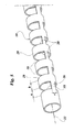
- Figure 5 illustrates a further embodiment of the tubular element 18, in which the apertures 20 are formed in the shape of rings interrupted along a generatrix by a bridge 26 connecting adjacent portions 28, also of annular shape, of the tubular element 18.
- Such apertures 20 can be characterised by means of their extent (a) in the axial direction, the extent (b) in the axial direction of the tubular portions 28 interposed between two adjacent apertures 20 and the extent (c) of the bridges 26 in the circumferential direction.
- the values of (a), (b) and (c) can be selected independently at will and maintained constant or made to vary along the axial extent of the element 18 so as to determine the rigidity of the prosthesis 10 in a desired manner in dependence on the point and direction of application of the stresses.
- Figure 6 illustrates a further embodiment of the tubular element 18, in which the apertures 20 have a sinuous shape limited in one or more portions by edges 30 in contact, or almost in contact, in the absence of external stresses.
- a prosthesis provided with a perforated tubular element 18 of this type opposes enlargement of the apertures 20 with a predetermined force in response to a traction stress, allowing the prosthesis to extend in the axial direction, whilst further closure of the apertures 20 in response to a compression stress is in fact prevented by the contacting edges 30, so that the behaviour of the prosthesis is similar in this case to that of a rigid body.
- Such a prosthesis thus has differentiated rigidity in response to stresses acting in the axial direction, being rather rigid in response to compression stresses but on the other hand deformable in response to traction stresses acting in the opposite sense along the same direction.
- Such behaviour is particularly convenient for encouraging, on the one hand, the natural dilatation of the annulus in the diastolic phase and, on the other hand, to guarantee the absence of compression and corrugation phenomena (pleating) following surgical suture during a valve repair operation.
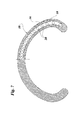
- Figure 7 illustrates a further embodiment of the prosthesis of the invention having an open ring shape and having a perforated element 18 of laminar or tubular structure.
- the shape, dimensions and/or spacing of the apertures 20 it is possible to obtain the desired variations in rigidity.
Abstract
Description
- The present invention relates in general to a device for cardiac valve repair operations, in particular a prosthesis for annuloplasty.
- The human heart has four cardiac valves: the mitral valve, the tricuspid valve, the pulmonary valve and the aortic valve.
- The mitral valve is situated in the left atrio-ventricular ostium and regulates the unidirectionality of the flow of blood from the atrium to the ventricle. It opens in the diastole and closes in the systole, preventing blood from flowing back from the ventricle to the atrium. The annulus of a normally functioning mitral valve is characterised by shape, dimensions and flexibility such as to allow a correct closure of the valve lips during the systolic phase. For example the mitral annulus has a characteristic "kidney" shape (or "D" shape), and is more flexible in the portion corresponding to the posteria lip of the valve. Illnesses or genetic defects can cause deformations or dilatations of the annulus of the mitral valve, resulting in an incomplete closure thereof with consequent regurgitation of blood.
- The same phenomena can occur in the tricuspid valve, situated between the right atrium and right ventricle.
- A frequently used method for eliminating some pathological alterations of the mitral and tricuspid valves is that of reinstating the correct shape and dimensions of the value annulus by means of surgical procedures known as annuloplasty.
- Annuloplasty consists in surgically implanting a supporting prosthesis on the dilated or deformed annulus for the purpose of reinstating its dimensions and/or physiological shape in such a way as to allow the cardiac valve to function correctly.
- Support prostheses utilised in valve repair operations are called annuloplasty prostheses. In the majority of cases such prostheses are constituted by a closed or open ring structure comprising an inner core and an outer cladding of biocompatible material which allows surgical suture.
- In the prior art various types of annuloplasty prostheses have been described.
- Initially, the prostheses proposed were predominantly of the rigid type for the purpose of drastically reducing the dilatation of the valve annulus. Such prostheses are generally constituted by a metal core (for example a titanium alloy), a possible sheath of cladding around the core and an outer cladding of textile for the suture. Rigid annuloplasty prostheses are described, for example, in US-4 055 861 of Carpentier et al, published 1 November 1977, and US-3 656 185 of Carpentier et al, published 18 April 1972.
- Rigid prostheses, although satisfactory as far as reinstatement of the shape and dimensions of the valve annulus are concerned, do not allow this latter to flex along the base of the posterior cuspid in such a way as to assist the cardiac muscle movements, with the consequence that significant stress is imposed on the suture points subjected to torsion and traction, preventing a natural behaviour of the valve.
- Therefore, subsequently, semi rigid or completely flexible prosthesis models were proposed. Completely flexible annuloplasty prostheses are for example described in US patents US-5 041 130, of Carpentier et al published 20 August 1991; US-5 716 397 of Myers et al published 10 February 1998; US-6 102 945 of Campbell et al published 15 August 2000; and US-5 064 431 of Gilbertson et al published 12 November 1991.
- The completely flexible prostheses follow the movements of the annulus during the cardiac cycle in an optimal manner. However they have the disadvantage of not allowing the shape to be reconstructed in an optimal manner.
- Semi-rigid prostheses seek to unite the advantages of those of the rigid type with those of the completely flexible type avoiding the disadvantages thereof.
- Semi rigid annuloplasty prostheses are for example described in US patents US-5 061 277 of Carpentier et al published 29 October 1991; US-5 104 407 of Lam et al published 14 April 1992; US-5 674 279 of Wright et al published 7 October 1997; US-5 824 066 of Gross et al published 20 October 1998; US-5 607 471 of Seguin et al published 4 March 1997; and US-6 143 024 of Campbell et al published 7 November 2000.
- In particular, US-5 104 407 describes a ring prosthesis comprising an annular support element which is substantially more rigid in one part than in the remainder. This more rigid part projects transversely with respect to the general plane in which the remaining part of the support element lies.
- US-5 607 471 on the other hand describes a ring prosthesis having variable transverse sections, and therefore differentiated rigidity along its circumferential extent.
- All these known prostheses have, however, limitations in relation to the possibility of exhibiting a variable rigidity in dependence on the point and/or direction and/or mode of application of the stresses.
- For example, US-5 103 407 provides a structure with variable rigidity in the plane of the ring, but with a limited possibility of flexure outside this plane.
- On the other hand, US-5 607 471 describes technical arrangements able to guarantee an improved flexibility out of the plane of the annulus. However, the possibility of effectively obtaining characteristics of variable rigidity of the prosthesis, for example, in its localised portions as well, appears significantly limited by the necessity to vary the area of the entire resistant section of the internal element. Moreover, the technical arrangements described in US-5 607 471 do not allow an optimal behaviour of the prosthesis in response to stresses in a tangential direction to be obtained (that is to say stresses directed along its longitudinal axis, which is usually closed in a ring), the rigidity in response to traction and compression at the same point of the internal element being substantially undifferentiated.
- The object of the present invention is that of providing a prosthesis for annuloplasty the rigidity of which can be made variable in a desired manner in dependence on the point, direction and mode (traction, compression, flexion, torsion) of application of the stresses.
- According to the invention, such object is achieved thanks to a prosthesis for annuloplasty comprising a laminar or tubular element having a plurality of apertures in at least one portion. This element can then be defined hereinafter in the present description as "perforated".
- In the perforated element the apertures can be formed substantially according to any arrangement and with any shape and dimensions, so as to obtain the desired rigidity variation. For example, a prosthesis provided with such a perforated element can have markedly different rigidity whilst having a constant transverse section, so as to satisfy possible requirements of uniformity of dimensions.
- The perforated element can be formed in its laminar form both with a flat development and with various three-dimensional shapes.
- Preferably, however, the perforated element is made in a tubular shape because this latter allows a more flexible and efficient arrangement of the apertures for the purpose of influencing the properties of rigidity of the prosthesis. As a matter of fact, the transverse section of the perforated tubular element can be of any shape, even if the circular section is that preferred for reasons of practicality and simplicity of production.
- The prostheses of the invention have the additional advantage of an easier suturability since the apertures formed in the perforated element can constitute, if necessary, preferential transit ways for the passage of a suture needle.
- There are no particular limitations in relation to the material usable for the production of the perforated element, which can thus be produced for example in metal, polymeric or composite material. For their part, the apertures can be formed in the perforated element with any conventional technology. For example, if the perforated element is made of metal, the apertures can be formed by piercing a performed tube by means of a laser, electro-erosion or cutting. If the perforated element were formed of polymeric material, it could be directly formed into its definitive shape for example by means of moulding technologies. Overall, therefore, the production of the prosthesis of the invention is simple and economical.
- Further advantages and characteristics of the invention will become apparent from the following detailed description provided purely by way of non limitative example, with reference to the attached drawings, in which:
- Figure 1 is a plan view, partially in section, of a prosthesis of the invention of closed ring type;
- Figure 2 is a prospective view, on an enlarged scale, of a tubular element forming part of the prosthesis of Figure 1;
- Figures from 3 to 6 are perspective views of respective alternative embodiments of the tubular element of Figure 2; and
- Figure 7 is a plan view, partially in section, of a further alternative open ring type embodiment of the prosthesis of the invention.
-
- The
reference 10 indicates in Figure 1 a prosthesis for annuloplasty the shape of which generally reproduces the geometry of the annulus of a mitral valve, that is to say a closed ring shaped in the form of a D with an approximately rectilinearintertrigonal section 12 and acurved section 14. - The
prosthesis 10 is externally clad, in a manner known per se by asheath 16 of biocompatible material, for example chosen from the group consisting of polymers, synthetic textiles, biological tissues and their combinations. - The
sheath 16 covers atubular ring element 18 having a transverse section of constant circular shape over its entire extent. Theelement 18 has in its wall (Figure 2) a plurality ofcircular apertures 20 spaced along two lines parallel to thelongitudinal axis 22 of theelement 18 and diametrically opposite one another across theaxis 22 in such a way that theapertures 20 have a spatial orientation substantially parallel to the general plane of theprosthesis 10. - There are no such apertures in the
intertrigonal section 12, which must be more rigid, whilst they gradually become more closely spaced towards the central part of thecurved section 14, which must be more flexible. - The internal cavity of the
element 18 may possibly be filled, partially or totally, with elastomeric material, in particular silicone, polyurethane and their mixtures, as for example described in European patent application No. 01830378.4 by the same applicant. - The surface of the
tubular element 18 and/or of thesheath 16 can be clad partially or totally with a thin layer of haemocompatible carbon, for example turbostratic carbon. The procedure for the production of such a cladding is, for example, described in the patents US-5 084 151, US-5 387 247, US-5 370 684, US-5 135 845 and US-5 423 886 of the same applicant. This cladding contributes to an improved haemocompatibility of theprosthesis 10 and to a controlled tissue growth of the receiving organism. - Figure 3 illustrates an alternative embodiment of the
tubular element 18, which has, in addition to the apertures illustrated in the preceding figure,further apertures 20 disposed along two lines parallel to thelongitudinal axis 22 of theelement 18 and diametrically opposite across theaxis 18 so as to have a substantially transverse spatial orientation with respect to the general plane of theprosthesis 10. - The presence of the
apertures 20 in the arrangement just described influences the rigidity characteristics of theprosthesis 10 under the action of stresses which act both in the general plane and transversely with respect to it. In particular, the prosthesis can be rendered, for example, less rigid against stresses which act in its general plane along an antero-posterior direction (that is to say in a direction distinguished by thereference numeral 24 in Figure 1), with respect to stresses which act in the general plane along a direction orthogonal to the antero-posterior direction. As far as the rigidity characteristics against stresses which act transversely with respect to the general plane of theprostheses 10 are concerned, they are for example chosen in such a way as to facilitate the assumption of a saddle shape in certain phases of the cardiac cycle. - The desired characteristics of variation in flexibility can also be obtained with a suitable variation of the dimensions of the
apertures 20 of theelement 18, as illustrated for example in Figure 4. - Figure 5 illustrates a further embodiment of the
tubular element 18, in which theapertures 20 are formed in the shape of rings interrupted along a generatrix by abridge 26 connectingadjacent portions 28, also of annular shape, of thetubular element 18.Such apertures 20 can be characterised by means of their extent (a) in the axial direction, the extent (b) in the axial direction of thetubular portions 28 interposed between twoadjacent apertures 20 and the extent (c) of thebridges 26 in the circumferential direction. The values of (a), (b) and (c) can be selected independently at will and maintained constant or made to vary along the axial extent of theelement 18 so as to determine the rigidity of theprosthesis 10 in a desired manner in dependence on the point and direction of application of the stresses. - Figure 6 illustrates a further embodiment of the
tubular element 18, in which theapertures 20 have a sinuous shape limited in one or more portions byedges 30 in contact, or almost in contact, in the absence of external stresses. A prosthesis provided with a perforatedtubular element 18 of this type opposes enlargement of theapertures 20 with a predetermined force in response to a traction stress, allowing the prosthesis to extend in the axial direction, whilst further closure of theapertures 20 in response to a compression stress is in fact prevented by the contactingedges 30, so that the behaviour of the prosthesis is similar in this case to that of a rigid body. Such a prosthesis thus has differentiated rigidity in response to stresses acting in the axial direction, being rather rigid in response to compression stresses but on the other hand deformable in response to traction stresses acting in the opposite sense along the same direction. Such behaviour is particularly convenient for encouraging, on the one hand, the natural dilatation of the annulus in the diastolic phase and, on the other hand, to guarantee the absence of compression and corrugation phenomena (pleating) following surgical suture during a valve repair operation. - It goes without saying that the arrangements of the
apertures 20 previously illustrated and/or described can be combined in any way in different portions of the sameperforated element 18 so as to regulate the rigidity of theprosthesis 10 in a desired manner in dependence on the point and direction of application of the stresses. Equally it is also possible, in embodiments of theperforated element 18 not illustrated, to arrange the apertures in an irregular manner rather than in a regularly repeating pattern. - Figure 7 illustrates a further embodiment of the prosthesis of the invention having an open ring shape and having a
perforated element 18 of laminar or tubular structure. In this case, too, by varying the shape, dimensions and/or spacing of theapertures 20 it is possible to obtain the desired variations in rigidity. - Naturally, the principle of the invention remaining the same, the details of construction and the embodiments can be widely varied with respect to what has been described purely by way of example, without by this departing from its ambit.
Claims (24)
- A prosthesis (10) for annuloplasty comprising a laminar or tubular element (18) having a plurality of apertures (20) in at least one portion thereof.
- A prosthesis (10) according to Claim 1, in which the shape, dimensions and arrangement of the said apertures (20) are chosen in such a way as to confer on the prosthesis (10) a differentiated flexibility depending on the location and direction of application of an external stress.
- A prosthesis (10) according to any preceding claim, in which the said apertures (20) have a constant shape but different spacing and dimensions along the said element (18).
- A prosthesis (10) according to any preceding claim, in which the said apertures (20) are disposed with a regularly repeating pattern.
- A prosthesis (10) according to any preceding claim, in which the said apertures (20) have a circular shape.
- A prosthesis (10) according to any preceding claim, in which the said apertures (20) are spaced along two lines parallel to the longitudinal axis (22) of the tubular element (18) and diametrically opposite one another across the said axis (22) in such a way that the said apertures (20) have a spatial orientation substantially parallel to the general plane of the prosthesis (10).
- A prosthesis (10) according to any preceding claim, in which the said apertures (20) are disposed along two lines parallel to the longitudinal axis (22) of the tubular element (18) and diametrically opposite one another across the said axis (22), in such a way that the said apertures (20) have a substantially transverse spatial orientation with respect to the general plane of the prosthesis (10).
- A prosthesis (10) according to any preceding claim from 1 to 4, in which the said apertures (20) have, at least in part, a sinuous form limited in one or more portions by edges (30), contacting or almost contacting each other in the absence of external stresses, in such a way that the said element has a differentiated rigidity in response to traction and compression stresses.
- A prosthesis (10) according to any preceding claim, in which the said tubular element (18) has a transverse section of circular shape.
- A prosthesis (10) according to any preceding claim, in which the said tubular element (18) has a transverse section of constant shape over its entire development.
- A prosthesis (10) according to any preceding claim, having a shape generally reproducing the geometry of the annulus of a cardiac valve.
- A prosthesis (10) according to Claim 11, having a shape generally reproducing the geometry of the annulus of a mitral valve.
- A prosthesis (10) according to Claim 11, having a shape generally reproducing the geometry of the annulus of a tricuspid valve.
- A prosthesis (10) according to any preceding claim, having a closed loop shape.
- A prosthesis (10) according to any preceding claim from 1 to 13, having an open loop shape.
- A prosthesis (10) according to any preceding claim, in which the said laminar or tubular element (18) is covered by a sheath (16) of biocompatible materials.
- A prosthesis (10) according to Claim 16, in which the said biocompatible material is chosen from the group consisting of polymers, synthetic textiles, biological tissues and their combinations.
- A prosthesis (10) according to any preceding claim, in which at least a portion of the surface of the said laminar or tubular element (18) and/or of the said sheath (16) is clad with haemocompatible carbon.
- A prosthesis (10) according to Claim 18, in which the said haemo-compatible carbon is turbostratic carbon.
- A prosthesis (10) according to any preceding claim, in which the said laminar or tubular element (18) is a metal, polymeric or composite material.
- A prosthesis (10) according to any preceding claim, in which the internal cavity of the said tubular element (18) is at least partially filled with elastomeric material.
- A prosthesis (10) according to Claim 21, in which the internal cavity of the said tubular element (18) is totally filled with elastomeric material.
- A prosthesis (10) according to any preceding claim, in which the said apertures (20) are formed by means of piercing laser, electroerosion or cutting of a blank metal element.
- A prosthesis (10) according to any preceding claim from 1 to 22 in which the said laminar or tubular element (18) is made by moulding polymeric material.
Priority Applications (8)
| Application Number | Priority Date | Filing Date | Title |
|---|---|---|---|
| EP09177502A EP2153799B1 (en) | 2002-03-27 | 2002-03-27 | A prosthesis for annuloplasty comprising a perforated element |
| ES09177502T ES2370585T3 (en) | 2002-03-27 | 2002-03-27 | PROSTHESIS FOR ANULOPLASTY THAT INCLUDES A PERFORATED ELEMENT. |
| DE60234675T DE60234675D1 (en) | 2002-03-27 | 2002-03-27 | Anuloplasty prosthesis with a pierced component |
| AT02425190T ATE451080T1 (en) | 2002-03-27 | 2002-03-27 | ANULOPLASTY PROSTHESIS WITH A PIERCED COMPONENT |
| AT09177502T ATE518501T1 (en) | 2002-03-27 | 2002-03-27 | ANNULOPLASTY PROSTHESIS WITH PERFORATED ELEMENT |
| EP02425190A EP1348406B1 (en) | 2002-03-27 | 2002-03-27 | A prosthesis for annuloplasty comprising a perforated element |
| US10/393,448 US7220277B2 (en) | 2002-03-27 | 2003-03-20 | Prosthesis for annuloplasty comprising a perforated element |
| US11/737,474 US20070191940A1 (en) | 2002-03-27 | 2007-04-19 | Prosthesis for annuloplasty comprising a perforated element |
Applications Claiming Priority (1)
| Application Number | Priority Date | Filing Date | Title |
|---|---|---|---|
| EP02425190A EP1348406B1 (en) | 2002-03-27 | 2002-03-27 | A prosthesis for annuloplasty comprising a perforated element |
Publications (2)
| Publication Number | Publication Date |
|---|---|
| EP1348406A1 true EP1348406A1 (en) | 2003-10-01 |
| EP1348406B1 EP1348406B1 (en) | 2009-12-09 |
Family
ID=27798967
Family Applications (2)
| Application Number | Title | Priority Date | Filing Date |
|---|---|---|---|
| EP09177502A Expired - Lifetime EP2153799B1 (en) | 2002-03-27 | 2002-03-27 | A prosthesis for annuloplasty comprising a perforated element |
| EP02425190A Expired - Lifetime EP1348406B1 (en) | 2002-03-27 | 2002-03-27 | A prosthesis for annuloplasty comprising a perforated element |
Family Applications Before (1)
| Application Number | Title | Priority Date | Filing Date |
|---|---|---|---|
| EP09177502A Expired - Lifetime EP2153799B1 (en) | 2002-03-27 | 2002-03-27 | A prosthesis for annuloplasty comprising a perforated element |
Country Status (5)
| Country | Link |
|---|---|
| US (2) | US7220277B2 (en) |
| EP (2) | EP2153799B1 (en) |
| AT (2) | ATE518501T1 (en) |
| DE (1) | DE60234675D1 (en) |
| ES (1) | ES2370585T3 (en) |
Cited By (11)
| Publication number | Priority date | Publication date | Assignee | Title |
|---|---|---|---|---|
| EP1629795A1 (en) * | 2004-06-29 | 2006-03-01 | SIEVERS, Hans-Hinrich, Dr. | Annuloplasty Ring |
| EP1719476A1 (en) * | 2005-05-06 | 2006-11-08 | Sorin Biomedica Cardio S.R.L. | Annuloplasty prosthesis |
| WO2007072399A1 (en) * | 2005-12-19 | 2007-06-28 | Robert William Mayo Frater | Annuloplasty prosthesis |
| EP1803420A1 (en) | 2005-12-28 | 2007-07-04 | Sorin Biomedica Cardio S.R.L. | Annuloplasty prosthesis with an auxetic structure |
| WO2010070455A1 (en) * | 2008-12-15 | 2010-06-24 | Jean-Paul Couetil | Annuloplasty ring with directional flexibilities and rigidities to assist the mitral annulus dynamics |
| US7758638B2 (en) | 2004-07-13 | 2010-07-20 | Ats Medical, Inc. | Implant with an annular base |
| US7914576B2 (en) | 2003-05-20 | 2011-03-29 | The Cleveland Clinic Foundation | Apparatus and methods for repair of a cardiac valve |
| ITTO20090785A1 (en) * | 2009-10-16 | 2011-04-17 | Uni Degli Studi Del Piemont E Orientale A | DEVICE FOR CORRECTION OF THE COMBINABLE MITRAL REGOLOR WITH A PROSTHESIS FOR ANULOPLASTICS, AND A KIT INCLUDING SUCH A DEVICE. |
| FR3004335A1 (en) * | 2013-04-11 | 2014-10-17 | Cormove | PARTIALLY DEFORMABLE ANNULOPLASTY PROSTHESIS |
| WO2015100857A1 (en) * | 2013-12-31 | 2015-07-09 | 金仕生物科技(常熟)有限公司 | Artificial heart valve annuloplasty ring |
| CN111031965A (en) * | 2017-07-18 | 2020-04-17 | 科法利欧斯有限公司 | Adjustable percutaneous annuloplasty devices, delivery systems, methods for percutaneously deploying an annuloplasty device, and methods performed by one or more processing devices |
Families Citing this family (96)
| Publication number | Priority date | Publication date | Assignee | Title |
|---|---|---|---|---|
| US7883539B2 (en) | 1997-01-02 | 2011-02-08 | Edwards Lifesciences Llc | Heart wall tension reduction apparatus and method |
| US7112219B2 (en) | 2002-11-12 | 2006-09-26 | Myocor, Inc. | Devices and methods for heart valve treatment |
| US8349001B2 (en) * | 2004-04-07 | 2013-01-08 | Medtronic, Inc. | Pharmacological delivery implement for use with cardiac repair devices |
| WO2006097931A2 (en) | 2005-03-17 | 2006-09-21 | Valtech Cardio, Ltd. | Mitral valve treatment techniques |
| EP1893131A1 (en) * | 2005-04-20 | 2008-03-05 | The Cleveland Clinic Foundation | Apparatus and method for replacing a cardiac valve |
| US20060247672A1 (en) * | 2005-04-27 | 2006-11-02 | Vidlund Robert M | Devices and methods for pericardial access |
| US8951285B2 (en) | 2005-07-05 | 2015-02-10 | Mitralign, Inc. | Tissue anchor, anchoring system and methods of using the same |
| US20070067027A1 (en) * | 2005-09-14 | 2007-03-22 | Micardia Corporation | Left atrial balloon catheter |
| JP2009543610A (en) * | 2006-07-12 | 2009-12-10 | ティグラン・カラピャン | Annuloplasty system and surgical method |
| US7879087B2 (en) * | 2006-10-06 | 2011-02-01 | Edwards Lifesciences Corporation | Mitral and tricuspid annuloplasty rings |
| US9883943B2 (en) | 2006-12-05 | 2018-02-06 | Valtech Cardio, Ltd. | Implantation of repair devices in the heart |
| US11259924B2 (en) | 2006-12-05 | 2022-03-01 | Valtech Cardio Ltd. | Implantation of repair devices in the heart |
| US11660190B2 (en) | 2007-03-13 | 2023-05-30 | Edwards Lifesciences Corporation | Tissue anchors, systems and methods, and devices |
| US8529620B2 (en) | 2007-05-01 | 2013-09-10 | Ottavio Alfieri | Inwardly-bowed tricuspid annuloplasty ring |
| US8784483B2 (en) | 2007-11-19 | 2014-07-22 | The Cleveland Clinic Foundation | Apparatus and method for treating a regurgitant heart valve |
| US8216303B2 (en) * | 2007-11-19 | 2012-07-10 | The Cleveland Clinic Foundation | Apparatus and method for treating a regurgitant heart valve |
| DE102008012113A1 (en) | 2008-03-02 | 2009-09-03 | Transcatheter Technologies Gmbh | Implant e.g. heart-valve-carrying stent, for e.g. arresting blood vessel, has fiber by which section of implant is reducible according to increasing of implant at extended diameter by unfolding or expansion of diameter with expansion unit |
| US8382829B1 (en) | 2008-03-10 | 2013-02-26 | Mitralign, Inc. | Method to reduce mitral regurgitation by cinching the commissure of the mitral valve |
| US9192472B2 (en) | 2008-06-16 | 2015-11-24 | Valtec Cardio, Ltd. | Annuloplasty devices and methods of delivery therefor |
| US8715342B2 (en) | 2009-05-07 | 2014-05-06 | Valtech Cardio, Ltd. | Annuloplasty ring with intra-ring anchoring |
| US8241351B2 (en) | 2008-12-22 | 2012-08-14 | Valtech Cardio, Ltd. | Adjustable partial annuloplasty ring and mechanism therefor |
| US10517719B2 (en) | 2008-12-22 | 2019-12-31 | Valtech Cardio, Ltd. | Implantation of repair devices in the heart |
| US9011530B2 (en) | 2008-12-22 | 2015-04-21 | Valtech Cardio, Ltd. | Partially-adjustable annuloplasty structure |
| WO2010073246A2 (en) | 2008-12-22 | 2010-07-01 | Valtech Cardio, Ltd. | Adjustable annuloplasty devices and adjustment mechanisms therefor |
| US8545553B2 (en) | 2009-05-04 | 2013-10-01 | Valtech Cardio, Ltd. | Over-wire rotation tool |
| US8353956B2 (en) | 2009-02-17 | 2013-01-15 | Valtech Cardio, Ltd. | Actively-engageable movement-restriction mechanism for use with an annuloplasty structure |
| US9968452B2 (en) | 2009-05-04 | 2018-05-15 | Valtech Cardio, Ltd. | Annuloplasty ring delivery cathethers |
| US10098737B2 (en) | 2009-10-29 | 2018-10-16 | Valtech Cardio, Ltd. | Tissue anchor for annuloplasty device |
| US9180007B2 (en) | 2009-10-29 | 2015-11-10 | Valtech Cardio, Ltd. | Apparatus and method for guide-wire based advancement of an adjustable implant |
| WO2011067770A1 (en) | 2009-12-02 | 2011-06-09 | Valtech Cardio, Ltd. | Delivery tool for implantation of spool assembly coupled to a helical anchor |
| US8870950B2 (en) | 2009-12-08 | 2014-10-28 | Mitral Tech Ltd. | Rotation-based anchoring of an implant |
| ES2365317B1 (en) | 2010-03-19 | 2012-08-03 | Xavier Ruyra Baliarda | PROTESTIC BAND, IN PARTICULAR FOR THE REPAIR OF A MITRAL VALVE. |
| US8579964B2 (en) | 2010-05-05 | 2013-11-12 | Neovasc Inc. | Transcatheter mitral valve prosthesis |
| US11653910B2 (en) | 2010-07-21 | 2023-05-23 | Cardiovalve Ltd. | Helical anchor implantation |
| US8932350B2 (en) | 2010-11-30 | 2015-01-13 | Edwards Lifesciences Corporation | Reduced dehiscence annuloplasty ring |
| US9308087B2 (en) | 2011-04-28 | 2016-04-12 | Neovasc Tiara Inc. | Sequentially deployed transcatheter mitral valve prosthesis |
| US9554897B2 (en) | 2011-04-28 | 2017-01-31 | Neovasc Tiara Inc. | Methods and apparatus for engaging a valve prosthesis with tissue |
| WO2012177942A2 (en) | 2011-06-21 | 2012-12-27 | Hanson Gifford, Iii | Prosthetic heart valve devices and associated systems and methods |
| US10792152B2 (en) | 2011-06-23 | 2020-10-06 | Valtech Cardio, Ltd. | Closed band for percutaneous annuloplasty |
| US9039757B2 (en) | 2011-10-19 | 2015-05-26 | Twelve, Inc. | Prosthetic heart valve devices, prosthetic mitral valves and associated systems and methods |
| EP2750630B1 (en) | 2011-10-19 | 2021-06-30 | Twelve, Inc. | Device for heart valve replacement |
| US11202704B2 (en) | 2011-10-19 | 2021-12-21 | Twelve, Inc. | Prosthetic heart valve devices, prosthetic mitral valves and associated systems and methods |
| JP6133309B2 (en) | 2011-10-19 | 2017-05-24 | トゥエルヴ, インコーポレイテッド | Prosthetic heart valve device |
| US8858623B2 (en) | 2011-11-04 | 2014-10-14 | Valtech Cardio, Ltd. | Implant having multiple rotational assemblies |
| EP3656434B1 (en) | 2011-11-08 | 2021-10-20 | Valtech Cardio, Ltd. | Controlled steering functionality for implant-delivery tool |
| US9345573B2 (en) | 2012-05-30 | 2016-05-24 | Neovasc Tiara Inc. | Methods and apparatus for loading a prosthesis onto a delivery system |
| WO2014052818A1 (en) | 2012-09-29 | 2014-04-03 | Mitralign, Inc. | Plication lock delivery system and method of use thereof |
| EP3730084A1 (en) | 2012-10-23 | 2020-10-28 | Valtech Cardio, Ltd. | Controlled steering functionality for implant-delivery tool |
| WO2014064695A2 (en) | 2012-10-23 | 2014-05-01 | Valtech Cardio, Ltd. | Percutaneous tissue anchor techniques |
| WO2014087402A1 (en) | 2012-12-06 | 2014-06-12 | Valtech Cardio, Ltd. | Techniques for guide-wire based advancement of a tool |
| US20150351906A1 (en) | 2013-01-24 | 2015-12-10 | Mitraltech Ltd. | Ventricularly-anchored prosthetic valves |
| US9724084B2 (en) | 2013-02-26 | 2017-08-08 | Mitralign, Inc. | Devices and methods for percutaneous tricuspid valve repair |
| US10449333B2 (en) | 2013-03-14 | 2019-10-22 | Valtech Cardio, Ltd. | Guidewire feeder |
| CN105283214B (en) | 2013-03-15 | 2018-10-16 | 北京泰德制药股份有限公司 | Translate conduit, system and its application method |
| US9572665B2 (en) | 2013-04-04 | 2017-02-21 | Neovasc Tiara Inc. | Methods and apparatus for delivering a prosthetic valve to a beating heart |
| CA2914505A1 (en) * | 2013-06-05 | 2014-12-11 | Lc Therapeutics, Inc. | Annuloplasty device |
| CN104010593B (en) * | 2013-07-29 | 2016-05-25 | 金仕生物科技(常熟)有限公司 | Artificial heart valve forming ring |
| ES2660196T3 (en) | 2013-08-14 | 2018-03-21 | Sorin Group Italia S.R.L. | String replacement device |
| US10070857B2 (en) | 2013-08-31 | 2018-09-11 | Mitralign, Inc. | Devices and methods for locating and implanting tissue anchors at mitral valve commissure |
| US10299793B2 (en) | 2013-10-23 | 2019-05-28 | Valtech Cardio, Ltd. | Anchor magazine |
| US9610162B2 (en) | 2013-12-26 | 2017-04-04 | Valtech Cardio, Ltd. | Implantation of flexible implant |
| ES2570077B1 (en) * | 2014-10-13 | 2017-03-03 | Jack KANOUZI BASCHOUR | Implantation prosthetic ring for the correction and prevention of breast areolar asymmetry |
| WO2016059639A1 (en) | 2014-10-14 | 2016-04-21 | Valtech Cardio Ltd. | Leaflet-restraining techniques |
| WO2016125160A1 (en) | 2015-02-05 | 2016-08-11 | Mitraltech Ltd. | Prosthetic valve with axially-sliding frames |
| US20160256269A1 (en) | 2015-03-05 | 2016-09-08 | Mitralign, Inc. | Devices for treating paravalvular leakage and methods use thereof |
| CN114515173A (en) | 2015-04-30 | 2022-05-20 | 瓦尔泰克卡迪欧有限公司 | Valvuloplasty techniques |
| US10751182B2 (en) | 2015-12-30 | 2020-08-25 | Edwards Lifesciences Corporation | System and method for reshaping right heart |
| WO2017117370A2 (en) | 2015-12-30 | 2017-07-06 | Mitralign, Inc. | System and method for reducing tricuspid regurgitation |
| CA3007670A1 (en) | 2016-01-29 | 2017-08-03 | Neovasc Tiara Inc. | Prosthetic valve for avoiding obstruction of outflow |
| US10531866B2 (en) | 2016-02-16 | 2020-01-14 | Cardiovalve Ltd. | Techniques for providing a replacement valve and transseptal communication |
| US10702274B2 (en) | 2016-05-26 | 2020-07-07 | Edwards Lifesciences Corporation | Method and system for closing left atrial appendage |
| GB201611910D0 (en) | 2016-07-08 | 2016-08-24 | Valtech Cardio Ltd | Adjustable annuloplasty device with alternating peaks and troughs |
| EP3848003A1 (en) | 2016-08-10 | 2021-07-14 | Cardiovalve Ltd. | Prosthetic valve with concentric frames |
| CN107753152A (en) * | 2016-08-22 | 2018-03-06 | 北京市普惠生物医学工程有限公司 | Valve forming ring |
| WO2018090148A1 (en) | 2016-11-21 | 2018-05-24 | Neovasc Tiara Inc. | Methods and systems for rapid retraction of a transcatheter heart valve delivery system |
| CN108618869B (en) * | 2017-03-17 | 2021-01-22 | 先健科技(深圳)有限公司 | Artificial heart valve forming ring |
| US10702378B2 (en) | 2017-04-18 | 2020-07-07 | Twelve, Inc. | Prosthetic heart valve device and associated systems and methods |
| US11045627B2 (en) | 2017-04-18 | 2021-06-29 | Edwards Lifesciences Corporation | Catheter system with linear actuation control mechanism |
| US10709591B2 (en) | 2017-06-06 | 2020-07-14 | Twelve, Inc. | Crimping device and method for loading stents and prosthetic heart valves |
| RU2666929C1 (en) * | 2017-06-21 | 2018-09-13 | федеральное государственное бюджетное учреждение "Национальный медицинский исследовательский центр имени Е.Н. Мешалкина" Министерства здравоохранения Российской Федерации (ФГБУ "НМИЦ им. ак. Е.Н. Мешалкина" Минздрава России) | Closed ring frame for annuloplasty of the mitral valve of the heart, method of its manufacture and application |
| US10786352B2 (en) | 2017-07-06 | 2020-09-29 | Twelve, Inc. | Prosthetic heart valve devices and associated systems and methods |
| US10729541B2 (en) | 2017-07-06 | 2020-08-04 | Twelve, Inc. | Prosthetic heart valve devices and associated systems and methods |
| CA3073834A1 (en) | 2017-08-25 | 2019-02-28 | Neovasc Tiara Inc. | Sequentially deployed transcatheter mitral valve prosthesis |
| US10835221B2 (en) | 2017-11-02 | 2020-11-17 | Valtech Cardio, Ltd. | Implant-cinching devices and systems |
| US11135062B2 (en) | 2017-11-20 | 2021-10-05 | Valtech Cardio Ltd. | Cinching of dilated heart muscle |
| CN116531147A (en) | 2018-01-24 | 2023-08-04 | 爱德华兹生命科学创新(以色列)有限公司 | Contraction of annuloplasty structures |
| EP3743014B1 (en) | 2018-01-26 | 2023-07-19 | Edwards Lifesciences Innovation (Israel) Ltd. | Techniques for facilitating heart valve tethering and chord replacement |
| CR20210020A (en) | 2018-07-12 | 2021-07-21 | Valtech Cardio Ltd | Annuloplasty systems and locking tools therefor |
| EP3876870B1 (en) | 2018-11-08 | 2023-12-20 | Neovasc Tiara Inc. | Ventricular deployment of a transcatheter mitral valve prosthesis |
| CA3135753C (en) | 2019-04-01 | 2023-10-24 | Neovasc Tiara Inc. | Controllably deployable prosthetic valve |
| US11491006B2 (en) | 2019-04-10 | 2022-11-08 | Neovasc Tiara Inc. | Prosthetic valve with natural blood flow |
| US11452599B2 (en) | 2019-05-02 | 2022-09-27 | Twelve, Inc. | Fluid diversion devices for hydraulic delivery systems and associated methods |
| AU2020279750B2 (en) | 2019-05-20 | 2023-07-13 | Neovasc Tiara Inc. | Introducer with hemostasis mechanism |
| EP3986332A4 (en) | 2019-06-20 | 2023-07-19 | Neovasc Tiara Inc. | Low profile prosthetic mitral valve |
| CA3142906A1 (en) | 2019-10-29 | 2021-05-06 | Valtech Cardio, Ltd. | Annuloplasty and tissue anchor technologies |
| RU206723U1 (en) * | 2021-02-08 | 2021-09-23 | Федеральное государственное бюджетное научное учреждение "Научно-исследовательский институт комплексных проблем сердечно-сосудистых заболеваний" (НИИ КПССЗ) | PERSONALIZED MITRAL VALVE PROSTHESIS RING WITH VARIABLE RIGIDITY |
Citations (5)
| Publication number | Priority date | Publication date | Assignee | Title |
|---|---|---|---|---|
| US5103407A (en) | 1989-02-21 | 1992-04-07 | Scitex Corporation | Apparatus and method for color selection |
| US5607471A (en) | 1993-08-03 | 1997-03-04 | Jacques Seguin | Prosthetic ring for heart surgery |
| US6106550A (en) * | 1998-07-10 | 2000-08-22 | Sulzer Carbomedics Inc. | Implantable attaching ring |
| US20010021874A1 (en) * | 1994-07-29 | 2001-09-13 | Alexandre Carpentier | Expandable annuloplasty ring |
| US20020010504A1 (en) * | 1996-02-14 | 2002-01-24 | Eckhard Alt | Tubular stent with oval struts |
Family Cites Families (29)
| Publication number | Priority date | Publication date | Assignee | Title |
|---|---|---|---|---|
| NL143127B (en) | 1969-02-04 | 1974-09-16 | Rhone Poulenc Sa | REINFORCEMENT DEVICE FOR A DEFECTIVE HEART VALVE. |
| FR2306671A1 (en) | 1975-04-11 | 1976-11-05 | Rhone Poulenc Ind | VALVULAR IMPLANT |
| SU577022A1 (en) * | 1976-06-25 | 1977-10-30 | Всесоюзный Научно-Исследовательский Институт Клинической И Экспериментальной Хирургии | Cardiac valve prosthesis |
| US5387247A (en) | 1983-10-25 | 1995-02-07 | Sorin Biomedia S.P.A. | Prosthetic device having a biocompatible carbon film thereon and a method of and apparatus for forming such device |
| US5084151A (en) | 1985-11-26 | 1992-01-28 | Sorin Biomedica S.P.A. | Method and apparatus for forming prosthetic device having a biocompatible carbon film thereon |
| CA1303298C (en) | 1986-08-06 | 1992-06-16 | Alain Carpentier | Flexible cardiac valvular support prosthesis |
| IT1196836B (en) | 1986-12-12 | 1988-11-25 | Sorin Biomedica Spa | Polymeric or metal alloy prosthesis with biocompatible carbon coating |
| US5133845A (en) | 1986-12-12 | 1992-07-28 | Sorin Biomedica, S.P.A. | Method for making prosthesis of polymeric material coated with biocompatible carbon |
| IT1210722B (en) | 1987-05-11 | 1989-09-20 | Sorin Biomedica Spa | DEVICES FOR THE CONDITIONING OF BLOOD FLOWS |
| IT1218951B (en) | 1988-01-12 | 1990-04-24 | Mario Morea | PROSTHETIC DEVICE FOR SURGICAL CORRECTION OF TRICUSPIDAL INSUFFICENCE |
| US4917698A (en) * | 1988-12-22 | 1990-04-17 | Baxter International Inc. | Multi-segmented annuloplasty ring prosthesis |
| EP0457842B1 (en) | 1989-02-13 | 1994-07-20 | Baxter International Inc. | Selectively flexible annuloplasty ring |
| US5041130A (en) | 1989-07-31 | 1991-08-20 | Baxter International Inc. | Flexible annuloplasty ring and holder |
| US5135845A (en) | 1990-04-10 | 1992-08-04 | Eastman Kodak Company | Sensitizing dye for photographic materials |
| US5064431A (en) | 1991-01-16 | 1991-11-12 | St. Jude Medical Incorporated | Annuloplasty ring |
| WO1993015690A2 (en) | 1992-01-27 | 1993-08-19 | Medtronic, Inc. | Annuloplasty and suture rings |
| WO1997019655A1 (en) | 1995-12-01 | 1997-06-05 | Medtronic, Inc. | Annuloplasty prosthesis |
| IT1285308B1 (en) | 1996-03-12 | 1998-06-03 | Sorin Biomedica Cardio Spa | PROCEDURE FOR THE PREPARATION OF BIOLOGICAL MATERIAL FOR PLANT |
| US5716397A (en) | 1996-12-06 | 1998-02-10 | Medtronic, Inc. | Annuloplasty device with removable stiffening element |
| US6309414B1 (en) * | 1997-11-04 | 2001-10-30 | Sorin Biomedica Cardio S.P.A. | Angioplasty stents |
| US6143024A (en) | 1998-06-04 | 2000-11-07 | Sulzer Carbomedics Inc. | Annuloplasty ring having flexible anterior portion |
| US6250308B1 (en) | 1998-06-16 | 2001-06-26 | Cardiac Concepts, Inc. | Mitral valve annuloplasty ring and method of implanting |
| US6102945A (en) * | 1998-10-16 | 2000-08-15 | Sulzer Carbomedics, Inc. | Separable annuloplasty ring |
| US6602289B1 (en) * | 1999-06-08 | 2003-08-05 | S&A Rings, Llc | Annuloplasty rings of particular use in surgery for the mitral valve |
| US6406493B1 (en) | 2000-06-02 | 2002-06-18 | Hosheng Tu | Expandable annuloplasty ring and methods of use |
| US6908482B2 (en) | 2001-08-28 | 2005-06-21 | Edwards Lifesciences Corporation | Three-dimensional annuloplasty ring and template |
| US6749630B2 (en) | 2001-08-28 | 2004-06-15 | Edwards Lifesciences Corporation | Tricuspid ring and template |
| US6797001B2 (en) | 2002-03-11 | 2004-09-28 | Cardiac Dimensions, Inc. | Device, assembly and method for mitral valve repair |
| US20030199974A1 (en) | 2002-04-18 | 2003-10-23 | Coalescent Surgical, Inc. | Annuloplasty apparatus and methods |
-
2002
- 2002-03-27 ES ES09177502T patent/ES2370585T3/en not_active Expired - Lifetime
- 2002-03-27 AT AT09177502T patent/ATE518501T1/en not_active IP Right Cessation
- 2002-03-27 AT AT02425190T patent/ATE451080T1/en not_active IP Right Cessation
- 2002-03-27 EP EP09177502A patent/EP2153799B1/en not_active Expired - Lifetime
- 2002-03-27 EP EP02425190A patent/EP1348406B1/en not_active Expired - Lifetime
- 2002-03-27 DE DE60234675T patent/DE60234675D1/en not_active Expired - Lifetime
-
2003
- 2003-03-20 US US10/393,448 patent/US7220277B2/en not_active Expired - Lifetime
-
2007
- 2007-04-19 US US11/737,474 patent/US20070191940A1/en not_active Abandoned
Patent Citations (5)
| Publication number | Priority date | Publication date | Assignee | Title |
|---|---|---|---|---|
| US5103407A (en) | 1989-02-21 | 1992-04-07 | Scitex Corporation | Apparatus and method for color selection |
| US5607471A (en) | 1993-08-03 | 1997-03-04 | Jacques Seguin | Prosthetic ring for heart surgery |
| US20010021874A1 (en) * | 1994-07-29 | 2001-09-13 | Alexandre Carpentier | Expandable annuloplasty ring |
| US20020010504A1 (en) * | 1996-02-14 | 2002-01-24 | Eckhard Alt | Tubular stent with oval struts |
| US6106550A (en) * | 1998-07-10 | 2000-08-22 | Sulzer Carbomedics Inc. | Implantable attaching ring |
Cited By (16)
| Publication number | Priority date | Publication date | Assignee | Title |
|---|---|---|---|---|
| US8480733B2 (en) | 2003-05-20 | 2013-07-09 | The Cleveland Clinic Foundation | Apparatus and methods for repair of a cardiac valve |
| US7914576B2 (en) | 2003-05-20 | 2011-03-29 | The Cleveland Clinic Foundation | Apparatus and methods for repair of a cardiac valve |
| US8512403B2 (en) | 2003-05-20 | 2013-08-20 | The Cleveland Clinic Foundation | Annuloplasty ring with wing members for repair of a cardiac valve |
| EP1913900A1 (en) * | 2004-06-29 | 2008-04-23 | SIEVERS, Hans-Hinrich, Dr. | Implant with a ring-shaped base plate |
| EP1629795A1 (en) * | 2004-06-29 | 2006-03-01 | SIEVERS, Hans-Hinrich, Dr. | Annuloplasty Ring |
| US7758638B2 (en) | 2004-07-13 | 2010-07-20 | Ats Medical, Inc. | Implant with an annular base |
| EP1719476A1 (en) * | 2005-05-06 | 2006-11-08 | Sorin Biomedica Cardio S.R.L. | Annuloplasty prosthesis |
| WO2007072399A1 (en) * | 2005-12-19 | 2007-06-28 | Robert William Mayo Frater | Annuloplasty prosthesis |
| EP1803420A1 (en) | 2005-12-28 | 2007-07-04 | Sorin Biomedica Cardio S.R.L. | Annuloplasty prosthesis with an auxetic structure |
| WO2010070455A1 (en) * | 2008-12-15 | 2010-06-24 | Jean-Paul Couetil | Annuloplasty ring with directional flexibilities and rigidities to assist the mitral annulus dynamics |
| ITTO20090785A1 (en) * | 2009-10-16 | 2011-04-17 | Uni Degli Studi Del Piemont E Orientale A | DEVICE FOR CORRECTION OF THE COMBINABLE MITRAL REGOLOR WITH A PROSTHESIS FOR ANULOPLASTICS, AND A KIT INCLUDING SUCH A DEVICE. |
| WO2011044994A1 (en) * | 2009-10-16 | 2011-04-21 | Universita' Degli Studi Del Piemonte Orientale "Amedeo Avogadro" | A device for correcting mitral regurgitation which can be combined with a prosthesis for annuloplasty, and kit comprising such a device |
| FR3004335A1 (en) * | 2013-04-11 | 2014-10-17 | Cormove | PARTIALLY DEFORMABLE ANNULOPLASTY PROSTHESIS |
| WO2015100857A1 (en) * | 2013-12-31 | 2015-07-09 | 金仕生物科技(常熟)有限公司 | Artificial heart valve annuloplasty ring |
| CN111031965A (en) * | 2017-07-18 | 2020-04-17 | 科法利欧斯有限公司 | Adjustable percutaneous annuloplasty devices, delivery systems, methods for percutaneously deploying an annuloplasty device, and methods performed by one or more processing devices |
| CN111031965B (en) * | 2017-07-18 | 2022-09-23 | 科法利欧斯有限公司 | Adjustable percutaneous annuloplasty devices, delivery systems, and methods performed by one or more treatment devices |
Also Published As
| Publication number | Publication date |
|---|---|
| DE60234675D1 (en) | 2010-01-21 |
| ES2370585T3 (en) | 2011-12-20 |
| ATE518501T1 (en) | 2011-08-15 |
| US20030220686A1 (en) | 2003-11-27 |
| EP2153799B1 (en) | 2011-08-03 |
| EP1348406B1 (en) | 2009-12-09 |
| EP2153799A1 (en) | 2010-02-17 |
| ATE451080T1 (en) | 2009-12-15 |
| US7220277B2 (en) | 2007-05-22 |
| US20070191940A1 (en) | 2007-08-16 |
Similar Documents
| Publication | Publication Date | Title |
|---|---|---|
| EP1348406B1 (en) | A prosthesis for annuloplasty comprising a perforated element | |
| US11903830B2 (en) | Physiologically harmonized repair of tricuspid valve | |
| US10188518B2 (en) | Annuloplasty ring with variable cross-section | |
| US10166101B2 (en) | Methods for repairing mitral valves | |
| EP1951154B1 (en) | Saddle-shaped mitral valve annuloplasty prostheses | |
| US5776189A (en) | Cardiac valvular support prosthesis | |
| EP1684670B1 (en) | Annulopasty rings for repair of abnormal mitral valves. | |
| EP2249745B1 (en) | Set of annuloplasty devices with varying anterior-posterior ratios | |
| US8114155B2 (en) | Annuloplasty ring with offset free ends | |
| US20110160849A1 (en) | Bimodal tricuspid annuloplasty ring | |
| EP3307208B1 (en) | Asymmetric mitral annuloplasty band | |
| EP0860151A1 (en) | Cardiac valvular support prosthesis | |
| WO2010070455A1 (en) | Annuloplasty ring with directional flexibilities and rigidities to assist the mitral annulus dynamics | |
| CA2195619A1 (en) | Cardiac valvular support prosthesis |
Legal Events
| Date | Code | Title | Description |
|---|---|---|---|
| PUAI | Public reference made under article 153(3) epc to a published international application that has entered the european phase |
Free format text: ORIGINAL CODE: 0009012 |
|
| AK | Designated contracting states |
Kind code of ref document: A1 Designated state(s): AT BE CH CY DE DK ES FI FR GB GR IE IT LI LU MC NL PT SE TR |
|
| AX | Request for extension of the european patent |
Extension state: AL LT LV MK RO SI |
|
| 17P | Request for examination filed |
Effective date: 20040324 |
|
| AKX | Designation fees paid |
Designated state(s): AT BE CH CY DE DK ES FI FR GB GR IE IT LI LU MC NL PT SE TR |
|
| 17Q | First examination report despatched |
Effective date: 20080526 |
|
| GRAP | Despatch of communication of intention to grant a patent |
Free format text: ORIGINAL CODE: EPIDOSNIGR1 |
|
| GRAC | Information related to communication of intention to grant a patent modified |
Free format text: ORIGINAL CODE: EPIDOSCIGR1 |
|
| GRAS | Grant fee paid |
Free format text: ORIGINAL CODE: EPIDOSNIGR3 |
|
| RAP1 | Party data changed (applicant data changed or rights of an application transferred) |
Owner name: SORIN BIOMEDICA CARDIO S.R.L. |
|
| GRAA | (expected) grant |
Free format text: ORIGINAL CODE: 0009210 |
|
| AK | Designated contracting states |
Kind code of ref document: B1 Designated state(s): AT BE CH CY DE DK ES FI FR GB GR IE IT LI LU MC NL PT SE TR |
|
| REG | Reference to a national code |
Ref country code: GB Ref legal event code: FG4D |
|
| REG | Reference to a national code |
Ref country code: CH Ref legal event code: EP |
|
| REG | Reference to a national code |
Ref country code: IE Ref legal event code: FG4D |
|
| REF | Corresponds to: |
Ref document number: 60234675 Country of ref document: DE Date of ref document: 20100121 Kind code of ref document: P |
|
| REG | Reference to a national code |
Ref country code: NL Ref legal event code: VDEP Effective date: 20091209 |
|
| PG25 | Lapsed in a contracting state [announced via postgrant information from national office to epo] |
Ref country code: SE Free format text: LAPSE BECAUSE OF FAILURE TO SUBMIT A TRANSLATION OF THE DESCRIPTION OR TO PAY THE FEE WITHIN THE PRESCRIBED TIME-LIMIT Effective date: 20091209 Ref country code: FI Free format text: LAPSE BECAUSE OF FAILURE TO SUBMIT A TRANSLATION OF THE DESCRIPTION OR TO PAY THE FEE WITHIN THE PRESCRIBED TIME-LIMIT Effective date: 20091209 |
|
| PG25 | Lapsed in a contracting state [announced via postgrant information from national office to epo] |
Ref country code: AT Free format text: LAPSE BECAUSE OF FAILURE TO SUBMIT A TRANSLATION OF THE DESCRIPTION OR TO PAY THE FEE WITHIN THE PRESCRIBED TIME-LIMIT Effective date: 20091209 |
|
| PG25 | Lapsed in a contracting state [announced via postgrant information from national office to epo] |
Ref country code: NL Free format text: LAPSE BECAUSE OF FAILURE TO SUBMIT A TRANSLATION OF THE DESCRIPTION OR TO PAY THE FEE WITHIN THE PRESCRIBED TIME-LIMIT Effective date: 20091209 Ref country code: ES Free format text: LAPSE BECAUSE OF FAILURE TO SUBMIT A TRANSLATION OF THE DESCRIPTION OR TO PAY THE FEE WITHIN THE PRESCRIBED TIME-LIMIT Effective date: 20100320 Ref country code: PT Free format text: LAPSE BECAUSE OF FAILURE TO SUBMIT A TRANSLATION OF THE DESCRIPTION OR TO PAY THE FEE WITHIN THE PRESCRIBED TIME-LIMIT Effective date: 20100409 |
|
| PG25 | Lapsed in a contracting state [announced via postgrant information from national office to epo] |
Ref country code: BE Free format text: LAPSE BECAUSE OF FAILURE TO SUBMIT A TRANSLATION OF THE DESCRIPTION OR TO PAY THE FEE WITHIN THE PRESCRIBED TIME-LIMIT Effective date: 20091209 |
|
| PLBE | No opposition filed within time limit |
Free format text: ORIGINAL CODE: 0009261 |
|
| STAA | Information on the status of an ep patent application or granted ep patent |
Free format text: STATUS: NO OPPOSITION FILED WITHIN TIME LIMIT |
|
| PG25 | Lapsed in a contracting state [announced via postgrant information from national office to epo] |
Ref country code: GR Free format text: LAPSE BECAUSE OF FAILURE TO SUBMIT A TRANSLATION OF THE DESCRIPTION OR TO PAY THE FEE WITHIN THE PRESCRIBED TIME-LIMIT Effective date: 20100310 Ref country code: CY Free format text: LAPSE BECAUSE OF FAILURE TO SUBMIT A TRANSLATION OF THE DESCRIPTION OR TO PAY THE FEE WITHIN THE PRESCRIBED TIME-LIMIT Effective date: 20091209 Ref country code: MC Free format text: LAPSE BECAUSE OF NON-PAYMENT OF DUE FEES Effective date: 20100331 |
|
| REG | Reference to a national code |
Ref country code: CH Ref legal event code: PL |
|
| 26N | No opposition filed |
Effective date: 20100910 |
|
| PG25 | Lapsed in a contracting state [announced via postgrant information from national office to epo] |
Ref country code: DK Free format text: LAPSE BECAUSE OF FAILURE TO SUBMIT A TRANSLATION OF THE DESCRIPTION OR TO PAY THE FEE WITHIN THE PRESCRIBED TIME-LIMIT Effective date: 20091209 Ref country code: IE Free format text: LAPSE BECAUSE OF NON-PAYMENT OF DUE FEES Effective date: 20100327 |
|
| PG25 | Lapsed in a contracting state [announced via postgrant information from national office to epo] |
Ref country code: CH Free format text: LAPSE BECAUSE OF NON-PAYMENT OF DUE FEES Effective date: 20100331 Ref country code: LI Free format text: LAPSE BECAUSE OF NON-PAYMENT OF DUE FEES Effective date: 20100331 |
|
| PG25 | Lapsed in a contracting state [announced via postgrant information from national office to epo] |
Ref country code: LU Free format text: LAPSE BECAUSE OF NON-PAYMENT OF DUE FEES Effective date: 20100327 |
|
| PG25 | Lapsed in a contracting state [announced via postgrant information from national office to epo] |
Ref country code: TR Free format text: LAPSE BECAUSE OF FAILURE TO SUBMIT A TRANSLATION OF THE DESCRIPTION OR TO PAY THE FEE WITHIN THE PRESCRIBED TIME-LIMIT Effective date: 20091209 |
|
| REG | Reference to a national code |
Ref country code: FR Ref legal event code: PLFP Year of fee payment: 15 |
|
| REG | Reference to a national code |
Ref country code: FR Ref legal event code: PLFP Year of fee payment: 16 |
|
| REG | Reference to a national code |
Ref country code: FR Ref legal event code: PLFP Year of fee payment: 17 |
|
| PGFP | Annual fee paid to national office [announced via postgrant information from national office to epo] |
Ref country code: IT Payment date: 20190326 Year of fee payment: 18 Ref country code: GB Payment date: 20190327 Year of fee payment: 18 Ref country code: DE Payment date: 20190312 Year of fee payment: 18 |
|
| PGFP | Annual fee paid to national office [announced via postgrant information from national office to epo] |
Ref country code: FR Payment date: 20190213 Year of fee payment: 18 |
|
| REG | Reference to a national code |
Ref country code: DE Ref legal event code: R119 Ref document number: 60234675 Country of ref document: DE |
|
| PG25 | Lapsed in a contracting state [announced via postgrant information from national office to epo] |
Ref country code: FR Free format text: LAPSE BECAUSE OF NON-PAYMENT OF DUE FEES Effective date: 20200331 Ref country code: DE Free format text: LAPSE BECAUSE OF NON-PAYMENT OF DUE FEES Effective date: 20201001 |
|
| GBPC | Gb: european patent ceased through non-payment of renewal fee |
Effective date: 20200327 |
|
| PG25 | Lapsed in a contracting state [announced via postgrant information from national office to epo] |
Ref country code: GB Free format text: LAPSE BECAUSE OF NON-PAYMENT OF DUE FEES Effective date: 20200327 |
|
| PG25 | Lapsed in a contracting state [announced via postgrant information from national office to epo] |
Ref country code: IT Free format text: LAPSE BECAUSE OF NON-PAYMENT OF DUE FEES Effective date: 20200327 |