EP1346856A2 - A system and method for determining the roll angle of a vehicle - Google Patents
A system and method for determining the roll angle of a vehicle Download PDFInfo
- Publication number
- EP1346856A2 EP1346856A2 EP03100122A EP03100122A EP1346856A2 EP 1346856 A2 EP1346856 A2 EP 1346856A2 EP 03100122 A EP03100122 A EP 03100122A EP 03100122 A EP03100122 A EP 03100122A EP 1346856 A2 EP1346856 A2 EP 1346856A2
- Authority
- EP
- European Patent Office
- Prior art keywords
- signal
- angle
- roll
- bank
- estimate
- Prior art date
- Legal status (The legal status is an assumption and is not a legal conclusion. Google has not performed a legal analysis and makes no representation as to the accuracy of the status listed.)
- Granted
Links
Images

Classifications
-
- B—PERFORMING OPERATIONS; TRANSPORTING
- B60—VEHICLES IN GENERAL
- B60T—VEHICLE BRAKE CONTROL SYSTEMS OR PARTS THEREOF; BRAKE CONTROL SYSTEMS OR PARTS THEREOF, IN GENERAL; ARRANGEMENT OF BRAKING ELEMENTS ON VEHICLES IN GENERAL; PORTABLE DEVICES FOR PREVENTING UNWANTED MOVEMENT OF VEHICLES; VEHICLE MODIFICATIONS TO FACILITATE COOLING OF BRAKES
- B60T8/00—Arrangements for adjusting wheel-braking force to meet varying vehicular or ground-surface conditions, e.g. limiting or varying distribution of braking force
- B60T8/17—Using electrical or electronic regulation means to control braking
- B60T8/172—Determining control parameters used in the regulation, e.g. by calculations involving measured or detected parameters
-
- B—PERFORMING OPERATIONS; TRANSPORTING
- B60—VEHICLES IN GENERAL
- B60G—VEHICLE SUSPENSION ARRANGEMENTS
- B60G17/00—Resilient suspensions having means for adjusting the spring or vibration-damper characteristics, for regulating the distance between a supporting surface and a sprung part of vehicle or for locking suspension during use to meet varying vehicular or surface conditions, e.g. due to speed or load
- B60G17/015—Resilient suspensions having means for adjusting the spring or vibration-damper characteristics, for regulating the distance between a supporting surface and a sprung part of vehicle or for locking suspension during use to meet varying vehicular or surface conditions, e.g. due to speed or load the regulating means comprising electric or electronic elements
- B60G17/016—Resilient suspensions having means for adjusting the spring or vibration-damper characteristics, for regulating the distance between a supporting surface and a sprung part of vehicle or for locking suspension during use to meet varying vehicular or surface conditions, e.g. due to speed or load the regulating means comprising electric or electronic elements characterised by their responsiveness, when the vehicle is travelling, to specific motion, a specific condition, or driver input
- B60G17/0162—Resilient suspensions having means for adjusting the spring or vibration-damper characteristics, for regulating the distance between a supporting surface and a sprung part of vehicle or for locking suspension during use to meet varying vehicular or surface conditions, e.g. due to speed or load the regulating means comprising electric or electronic elements characterised by their responsiveness, when the vehicle is travelling, to specific motion, a specific condition, or driver input mainly during a motion involving steering operation, e.g. cornering, overtaking
-
- B—PERFORMING OPERATIONS; TRANSPORTING
- B60—VEHICLES IN GENERAL
- B60G—VEHICLE SUSPENSION ARRANGEMENTS
- B60G17/00—Resilient suspensions having means for adjusting the spring or vibration-damper characteristics, for regulating the distance between a supporting surface and a sprung part of vehicle or for locking suspension during use to meet varying vehicular or surface conditions, e.g. due to speed or load
- B60G17/015—Resilient suspensions having means for adjusting the spring or vibration-damper characteristics, for regulating the distance between a supporting surface and a sprung part of vehicle or for locking suspension during use to meet varying vehicular or surface conditions, e.g. due to speed or load the regulating means comprising electric or electronic elements
- B60G17/019—Resilient suspensions having means for adjusting the spring or vibration-damper characteristics, for regulating the distance between a supporting surface and a sprung part of vehicle or for locking suspension during use to meet varying vehicular or surface conditions, e.g. due to speed or load the regulating means comprising electric or electronic elements characterised by the type of sensor or the arrangement thereof
-
- B—PERFORMING OPERATIONS; TRANSPORTING
- B60—VEHICLES IN GENERAL
- B60G—VEHICLE SUSPENSION ARRANGEMENTS
- B60G17/00—Resilient suspensions having means for adjusting the spring or vibration-damper characteristics, for regulating the distance between a supporting surface and a sprung part of vehicle or for locking suspension during use to meet varying vehicular or surface conditions, e.g. due to speed or load
- B60G17/015—Resilient suspensions having means for adjusting the spring or vibration-damper characteristics, for regulating the distance between a supporting surface and a sprung part of vehicle or for locking suspension during use to meet varying vehicular or surface conditions, e.g. due to speed or load the regulating means comprising electric or electronic elements
- B60G17/0195—Resilient suspensions having means for adjusting the spring or vibration-damper characteristics, for regulating the distance between a supporting surface and a sprung part of vehicle or for locking suspension during use to meet varying vehicular or surface conditions, e.g. due to speed or load the regulating means comprising electric or electronic elements characterised by the regulation being combined with other vehicle control systems
-
- B—PERFORMING OPERATIONS; TRANSPORTING
- B60—VEHICLES IN GENERAL
- B60W—CONJOINT CONTROL OF VEHICLE SUB-UNITS OF DIFFERENT TYPE OR DIFFERENT FUNCTION; CONTROL SYSTEMS SPECIALLY ADAPTED FOR HYBRID VEHICLES; ROAD VEHICLE DRIVE CONTROL SYSTEMS FOR PURPOSES NOT RELATED TO THE CONTROL OF A PARTICULAR SUB-UNIT
- B60W40/00—Estimation or calculation of non-directly measurable driving parameters for road vehicle drive control systems not related to the control of a particular sub unit, e.g. by using mathematical models
- B60W40/10—Estimation or calculation of non-directly measurable driving parameters for road vehicle drive control systems not related to the control of a particular sub unit, e.g. by using mathematical models related to vehicle motion
- B60W40/112—Roll movement
-
- B—PERFORMING OPERATIONS; TRANSPORTING
- B60—VEHICLES IN GENERAL
- B60G—VEHICLE SUSPENSION ARRANGEMENTS
- B60G2400/00—Indexing codes relating to detected, measured or calculated conditions or factors
- B60G2400/05—Attitude
- B60G2400/051—Angle
- B60G2400/0511—Roll angle
-
- B—PERFORMING OPERATIONS; TRANSPORTING
- B60—VEHICLES IN GENERAL
- B60G—VEHICLE SUSPENSION ARRANGEMENTS
- B60G2400/00—Indexing codes relating to detected, measured or calculated conditions or factors
- B60G2400/05—Attitude
- B60G2400/052—Angular rate
- B60G2400/0521—Roll rate
-
- B—PERFORMING OPERATIONS; TRANSPORTING
- B60—VEHICLES IN GENERAL
- B60G—VEHICLE SUSPENSION ARRANGEMENTS
- B60G2400/00—Indexing codes relating to detected, measured or calculated conditions or factors
- B60G2400/10—Acceleration; Deceleration
- B60G2400/104—Acceleration; Deceleration lateral or transversal with regard to vehicle
-
- B—PERFORMING OPERATIONS; TRANSPORTING
- B60—VEHICLES IN GENERAL
- B60G—VEHICLE SUSPENSION ARRANGEMENTS
- B60G2400/00—Indexing codes relating to detected, measured or calculated conditions or factors
- B60G2400/20—Speed
- B60G2400/204—Vehicle speed
-
- B—PERFORMING OPERATIONS; TRANSPORTING
- B60—VEHICLES IN GENERAL
- B60G—VEHICLE SUSPENSION ARRANGEMENTS
- B60G2400/00—Indexing codes relating to detected, measured or calculated conditions or factors
- B60G2400/40—Steering conditions
- B60G2400/41—Steering angle
-
- B—PERFORMING OPERATIONS; TRANSPORTING
- B60—VEHICLES IN GENERAL
- B60G—VEHICLE SUSPENSION ARRANGEMENTS
- B60G2400/00—Indexing codes relating to detected, measured or calculated conditions or factors
- B60G2400/80—Exterior conditions
- B60G2400/82—Ground surface
-
- B—PERFORMING OPERATIONS; TRANSPORTING
- B60—VEHICLES IN GENERAL
- B60G—VEHICLE SUSPENSION ARRANGEMENTS
- B60G2600/00—Indexing codes relating to particular elements, systems or processes used on suspension systems or suspension control systems
- B60G2600/60—Signal noise suppression; Electronic filtering means
- B60G2600/602—Signal noise suppression; Electronic filtering means high pass
-
- B—PERFORMING OPERATIONS; TRANSPORTING
- B60—VEHICLES IN GENERAL
- B60G—VEHICLE SUSPENSION ARRANGEMENTS
- B60G2600/00—Indexing codes relating to particular elements, systems or processes used on suspension systems or suspension control systems
- B60G2600/60—Signal noise suppression; Electronic filtering means
- B60G2600/604—Signal noise suppression; Electronic filtering means low pass
-
- B—PERFORMING OPERATIONS; TRANSPORTING
- B60—VEHICLES IN GENERAL
- B60G—VEHICLE SUSPENSION ARRANGEMENTS
- B60G2800/00—Indexing codes relating to the type of movement or to the condition of the vehicle and to the end result to be achieved by the control action
- B60G2800/01—Attitude or posture control
- B60G2800/012—Rolling condition
-
- B—PERFORMING OPERATIONS; TRANSPORTING
- B60—VEHICLES IN GENERAL
- B60G—VEHICLE SUSPENSION ARRANGEMENTS
- B60G2800/00—Indexing codes relating to the type of movement or to the condition of the vehicle and to the end result to be achieved by the control action
- B60G2800/01—Attitude or posture control
- B60G2800/019—Inclination due to load distribution or road gradient
- B60G2800/0194—Inclination due to load distribution or road gradient transversal with regard to vehicle
-
- B—PERFORMING OPERATIONS; TRANSPORTING
- B60—VEHICLES IN GENERAL
- B60G—VEHICLE SUSPENSION ARRANGEMENTS
- B60G2800/00—Indexing codes relating to the type of movement or to the condition of the vehicle and to the end result to be achieved by the control action
- B60G2800/24—Steering, cornering
-
- B—PERFORMING OPERATIONS; TRANSPORTING
- B60—VEHICLES IN GENERAL
- B60G—VEHICLE SUSPENSION ARRANGEMENTS
- B60G2800/00—Indexing codes relating to the type of movement or to the condition of the vehicle and to the end result to be achieved by the control action
- B60G2800/70—Estimating or calculating vehicle parameters or state variables
- B60G2800/702—Improving accuracy of a sensor signal
-
- B—PERFORMING OPERATIONS; TRANSPORTING
- B60—VEHICLES IN GENERAL
- B60T—VEHICLE BRAKE CONTROL SYSTEMS OR PARTS THEREOF; BRAKE CONTROL SYSTEMS OR PARTS THEREOF, IN GENERAL; ARRANGEMENT OF BRAKING ELEMENTS ON VEHICLES IN GENERAL; PORTABLE DEVICES FOR PREVENTING UNWANTED MOVEMENT OF VEHICLES; VEHICLE MODIFICATIONS TO FACILITATE COOLING OF BRAKES
- B60T2210/00—Detection or estimation of road or environment conditions; Detection or estimation of road shapes
- B60T2210/20—Road shapes
- B60T2210/22—Banked curves
-
- B—PERFORMING OPERATIONS; TRANSPORTING
- B60—VEHICLES IN GENERAL
- B60T—VEHICLE BRAKE CONTROL SYSTEMS OR PARTS THEREOF; BRAKE CONTROL SYSTEMS OR PARTS THEREOF, IN GENERAL; ARRANGEMENT OF BRAKING ELEMENTS ON VEHICLES IN GENERAL; PORTABLE DEVICES FOR PREVENTING UNWANTED MOVEMENT OF VEHICLES; VEHICLE MODIFICATIONS TO FACILITATE COOLING OF BRAKES
- B60T2230/00—Monitoring, detecting special vehicle behaviour; Counteracting thereof
- B60T2230/03—Overturn, rollover
-
- B—PERFORMING OPERATIONS; TRANSPORTING
- B60—VEHICLES IN GENERAL
- B60W—CONJOINT CONTROL OF VEHICLE SUB-UNITS OF DIFFERENT TYPE OR DIFFERENT FUNCTION; CONTROL SYSTEMS SPECIALLY ADAPTED FOR HYBRID VEHICLES; ROAD VEHICLE DRIVE CONTROL SYSTEMS FOR PURPOSES NOT RELATED TO THE CONTROL OF A PARTICULAR SUB-UNIT
- B60W50/00—Details of control systems for road vehicle drive control not related to the control of a particular sub-unit, e.g. process diagnostic or vehicle driver interfaces
- B60W2050/0001—Details of the control system
- B60W2050/0043—Signal treatments, identification of variables or parameters, parameter estimation or state estimation
- B60W2050/0052—Filtering, filters
- B60W2050/0054—Cut-off filters, retarders, delaying means, dead zones, threshold values or cut-off frequency
- B60W2050/0055—High-pass filters
-
- B—PERFORMING OPERATIONS; TRANSPORTING
- B60—VEHICLES IN GENERAL
- B60W—CONJOINT CONTROL OF VEHICLE SUB-UNITS OF DIFFERENT TYPE OR DIFFERENT FUNCTION; CONTROL SYSTEMS SPECIALLY ADAPTED FOR HYBRID VEHICLES; ROAD VEHICLE DRIVE CONTROL SYSTEMS FOR PURPOSES NOT RELATED TO THE CONTROL OF A PARTICULAR SUB-UNIT
- B60W50/00—Details of control systems for road vehicle drive control not related to the control of a particular sub-unit, e.g. process diagnostic or vehicle driver interfaces
- B60W2050/0001—Details of the control system
- B60W2050/0043—Signal treatments, identification of variables or parameters, parameter estimation or state estimation
- B60W2050/0052—Filtering, filters
- B60W2050/0054—Cut-off filters, retarders, delaying means, dead zones, threshold values or cut-off frequency
- B60W2050/0056—Low-pass filters
-
- B—PERFORMING OPERATIONS; TRANSPORTING
- B60—VEHICLES IN GENERAL
- B60W—CONJOINT CONTROL OF VEHICLE SUB-UNITS OF DIFFERENT TYPE OR DIFFERENT FUNCTION; CONTROL SYSTEMS SPECIALLY ADAPTED FOR HYBRID VEHICLES; ROAD VEHICLE DRIVE CONTROL SYSTEMS FOR PURPOSES NOT RELATED TO THE CONTROL OF A PARTICULAR SUB-UNIT
- B60W2510/00—Input parameters relating to a particular sub-units
- B60W2510/20—Steering systems
-
- B—PERFORMING OPERATIONS; TRANSPORTING
- B60—VEHICLES IN GENERAL
- B60W—CONJOINT CONTROL OF VEHICLE SUB-UNITS OF DIFFERENT TYPE OR DIFFERENT FUNCTION; CONTROL SYSTEMS SPECIALLY ADAPTED FOR HYBRID VEHICLES; ROAD VEHICLE DRIVE CONTROL SYSTEMS FOR PURPOSES NOT RELATED TO THE CONTROL OF A PARTICULAR SUB-UNIT
- B60W2520/00—Input parameters relating to overall vehicle dynamics
- B60W2520/10—Longitudinal speed
-
- B—PERFORMING OPERATIONS; TRANSPORTING
- B60—VEHICLES IN GENERAL
- B60W—CONJOINT CONTROL OF VEHICLE SUB-UNITS OF DIFFERENT TYPE OR DIFFERENT FUNCTION; CONTROL SYSTEMS SPECIALLY ADAPTED FOR HYBRID VEHICLES; ROAD VEHICLE DRIVE CONTROL SYSTEMS FOR PURPOSES NOT RELATED TO THE CONTROL OF A PARTICULAR SUB-UNIT
- B60W2520/00—Input parameters relating to overall vehicle dynamics
- B60W2520/12—Lateral speed
- B60W2520/125—Lateral acceleration
-
- B—PERFORMING OPERATIONS; TRANSPORTING
- B60—VEHICLES IN GENERAL
- B60W—CONJOINT CONTROL OF VEHICLE SUB-UNITS OF DIFFERENT TYPE OR DIFFERENT FUNCTION; CONTROL SYSTEMS SPECIALLY ADAPTED FOR HYBRID VEHICLES; ROAD VEHICLE DRIVE CONTROL SYSTEMS FOR PURPOSES NOT RELATED TO THE CONTROL OF A PARTICULAR SUB-UNIT
- B60W2520/00—Input parameters relating to overall vehicle dynamics
- B60W2520/18—Roll
-
- B—PERFORMING OPERATIONS; TRANSPORTING
- B60—VEHICLES IN GENERAL
- B60W—CONJOINT CONTROL OF VEHICLE SUB-UNITS OF DIFFERENT TYPE OR DIFFERENT FUNCTION; CONTROL SYSTEMS SPECIALLY ADAPTED FOR HYBRID VEHICLES; ROAD VEHICLE DRIVE CONTROL SYSTEMS FOR PURPOSES NOT RELATED TO THE CONTROL OF A PARTICULAR SUB-UNIT
- B60W2540/00—Input parameters relating to occupants
- B60W2540/18—Steering angle
-
- B—PERFORMING OPERATIONS; TRANSPORTING
- B60—VEHICLES IN GENERAL
- B60W—CONJOINT CONTROL OF VEHICLE SUB-UNITS OF DIFFERENT TYPE OR DIFFERENT FUNCTION; CONTROL SYSTEMS SPECIALLY ADAPTED FOR HYBRID VEHICLES; ROAD VEHICLE DRIVE CONTROL SYSTEMS FOR PURPOSES NOT RELATED TO THE CONTROL OF A PARTICULAR SUB-UNIT
- B60W2552/00—Input parameters relating to infrastructure
- B60W2552/15—Road slope
-
- B—PERFORMING OPERATIONS; TRANSPORTING
- B60—VEHICLES IN GENERAL
- B60W—CONJOINT CONTROL OF VEHICLE SUB-UNITS OF DIFFERENT TYPE OR DIFFERENT FUNCTION; CONTROL SYSTEMS SPECIALLY ADAPTED FOR HYBRID VEHICLES; ROAD VEHICLE DRIVE CONTROL SYSTEMS FOR PURPOSES NOT RELATED TO THE CONTROL OF A PARTICULAR SUB-UNIT
- B60W2720/00—Output or target parameters relating to overall vehicle dynamics
- B60W2720/18—Roll
-
- B—PERFORMING OPERATIONS; TRANSPORTING
- B60—VEHICLES IN GENERAL
- B60W—CONJOINT CONTROL OF VEHICLE SUB-UNITS OF DIFFERENT TYPE OR DIFFERENT FUNCTION; CONTROL SYSTEMS SPECIALLY ADAPTED FOR HYBRID VEHICLES; ROAD VEHICLE DRIVE CONTROL SYSTEMS FOR PURPOSES NOT RELATED TO THE CONTROL OF A PARTICULAR SUB-UNIT
- B60W30/00—Purposes of road vehicle drive control systems not related to the control of a particular sub-unit, e.g. of systems using conjoint control of vehicle sub-units, or advanced driver assistance systems for ensuring comfort, stability and safety or drive control systems for propelling or retarding the vehicle
- B60W30/02—Control of vehicle driving stability
- B60W30/04—Control of vehicle driving stability related to roll-over prevention
Landscapes
- Engineering & Computer Science (AREA)
- Mechanical Engineering (AREA)
- Automation & Control Theory (AREA)
- Transportation (AREA)
- Physics & Mathematics (AREA)
- Mathematical Physics (AREA)
- Control Of Driving Devices And Active Controlling Of Vehicle (AREA)
- Vehicle Body Suspensions (AREA)
- Length Measuring Devices With Unspecified Measuring Means (AREA)
- Steering Control In Accordance With Driving Conditions (AREA)
Abstract
Description
- The present invention relates generally to a method for determining the roll angle of a moving vehicle. More particularly, the present invention relates to a method for detecting the roll angle under dynamic lateral operating conditions for use in a motor vehicle having a yaw or rollover control system.
- Automotive vehicles with braking systems which respond to vehicle conditions as well as driver input have been produced. For example, when a particular yaw rate is desired, as indicated by a driver's steering wheel operation, if the vehicle is not producing an adequate yaw rate, the braking system of the vehicle may compensate by altering a particular wheel's speed. This control is dependent on accurate measurement of several vehicle operating conditions. It has been observed that error can be introduced in the control system if the vehicle is operating on a banked surface. Therefore, it is desirable to determine the bias in the various operating condition signals introduced by operating on a banked surface.
- U.S. Patent Number 5,446,658 ('658) addresses the problem of estimating bank angles of a road surface. However, under various operating conditions, the system described in the '658 patent does not have the ability to calculate the road surface bank angle under dynamic lateral operating conditions. Specifically, if the yaw rate for the vehicle changes by more than a predetermined threshold, the previously determined bank angle is assumed as the current bank angle. Of course, it is quite possible for a vehicle to undergo extreme bank angle variation during the period that the yaw rate is not within a predetermined threshold.
- U.S. Patent Number 6,073,065 provides a method for determining a bank angle experienced by a motor vehicle that is robust to dynamic lateral vehicle operations. However, the methodology reaches its limitation during high frequency manoeuvres with simultaneous road bank variation. The estimation during dynamic manoeuvres may experience some instantaneous errors.
- A paper presented by Y. Fukada entitled "Estimation of Vehicle Slip-Angle With Combination Method of Model Observer and Direct Integration", presented at the International Symposium on Advance Vehicle Control in September 1998, addresses the estimation of road bank angle with vehicle slip angle. In this paper, the difference between lateral force measured with a lateral accelerometer and the tire model estimated lateral force is used to obtain the road bank angle. However, its accuracy is contingent on the accuracy of the estimated lateral tire force, which, in turn depends on the accuracy of the road surfaces and lateral velocity. In this approach, the lateral velocity in road bank angle estimation is believed to be, at best, a convoluted process. Also, the accuracy and robustness of such a calculation is suspect.
- In roll sensing systems, three accelerometers and three angular rate sensors have been used. Together the sensors track the position and attitude of the vehicle. One problem with such systems is that the output of the sensors is susceptible to cumulative drift errors. Some gyroscopic sensors are available to minimize drift but are typically unsuitable and too expensive for automotive applications. U.S. Patents 6,038,495 and 6,212,455 use automotive grade sensors to determine rollover of the vehicle. Such systems take advantage of short-term integration and/or an inclinometer for bias correction. However, such systems are not capable of detecting sustained road surfaces such as the road bank during a turn. Under bank conditions, the frame of reference changes and therefore the output does not provide a reliable vehicle roll attitude. The '495 patent, for example, uses integration with a high pass filter while the '455 patent uses a lateral accelerometer/inclinometer to provide long term offset compensation. During bank turn conditions, the steady state roll is no longer zero and the lateral acceleration is not a good indication of the vehicle roll angle. Therefore, neither of these approaches provides robust roll angle estimation for road disturbances such as road bank angles, and in particular, sustained road bank angles.
- It would be desirable to determine roll angle under a variety of conditions including a bank angle being experienced by the vehicle.
- It is an object of this invention to provide an improved system and method for determining the roll angle of a vehicle.
- According to a first aspect of the invention there is provided a system for controlling a vehicle characterised in that the system comprises a lateral acceleration sensor generating a lateral acceleration signal corresponding to a lateral acceleration of the vehicle, a yaw rate sensor generating a yaw rate signal corresponding to a yaw rate of the vehicle, a steering wheel angle sensor generating a steering wheel angle signal corresponding to a steering wheel angle of the vehicle, a speed sensor generating a speed signal corresponding to the longitudinal speed of the vehicle, a roll rate sensor generating a roll rate signal; and a controller coupled to the lateral acceleration sensor, the yaw rate sensor, the steering wheel angle sensor and the speed sensor wherein the controller is operable to calculate a first roll angle signal in response to the roll rate signal, to calculate a bank angle signal in response to the lateral acceleration, the yaw rate, the steering wheel and the speed signals, and is further operable to sum the first roll angle signal and the bank angle signal to obtain a final roll angle estimate.
- The system may further comprise a high pass filter filtering the first roll angle signal.
- The controller may calculate a second roll angle signal corresponding to a suspension reference roll angle in response to the lateral acceleration signal, and sum the first roll angle signal, the second roll angle signal and the bank angle signal to obtain a final roll angle estimate.
- The system may further comprise a first low pass filter to filter the second roll angle signal.
- The system may further comprise a bank angle filter to filter the bank angle signal.
- The controller may further comprise an integrator to integrate the roll rate signal to obtain the first roll angle signal.
- The controller may be operable to calculate a first bank angle estimate dependent on the lateral acceleration signal, calculate a second bank angle estimate dependent on the yaw rate signal, calculate a third bank angle estimate dependent on both the lateral acceleration signal and the second yaw rate signal, calculate a dynamic compensation factor based upon a function of the first bank angle estimate, the second bank angle estimate and the third bank angle estimate, decompose the third bank angle estimate into a plurality of third bank angle frequency bands, reduce each of the plurality of third bank angle frequency bands in response to a multiplicative factor, the multiplicative factor being a function of the dynamic compensation factor to obtain a plurality of reduced third bank angles, and calculate a final bank angle bias estimate based on a sum of the plurality of reduced third bank angles.
- According to a second aspect of the invention there is provided a method of determining a roll angle of a vehicle characterised in that the method comprises providing a lateral acceleration signal corresponding to a lateral acceleration of the vehicle, providing a yaw rate signal corresponding to a yaw rate of the vehicle, providing a steering wheel signal responsive to a sensed steering wheel angle of the vehicle, providing a speed signal corresponding to a vehicle speed, calculating a first bank angle estimate dependent on the lateral acceleration signal, the yaw rate signal, the steering wheel signal and the speed signal, calculating a suspension reference roll angle in response to the lateral acceleration signal and calculating a conservative bank angle estimate signal in response to the first bank angle estimate and the suspension roll reference angle.
- The method may further comprise providing a roll rate signal corresponding to the roll rate of the vehicle, integrating the roll rate signal to obtain a roll-rate based roll angle and summing the conservative bank angle estimate, the suspension reference roll angle and the roll-rate based roll angle to obtain a final roll angle estimate.
- The method may further comprise high pass filtering the roll-rate based roll angle prior to the summing.
- The method may further comprise low pass filtering the conservative bank angle estimate signal.
- Calculating a first bank angle estimate may comprise calculating a first bank angle estimate dependent on the lateral acceleration signal and the method further comprises calculating a second bank angle estimate dependent on the yaw rate signal, calculating a third bank angle estimate dependent on both the lateral acceleration signal and the yaw rate signal, calculating a dynamic compensation factor based as a function of the first bank angle estimate, the second bank angle estimate and the third bank angle estimate, decomposing the third bank angle estimate into a plurality of third bank angle frequency bands, reducing each of the plurality of third bank angle frequency bands in response to a multiplicative factor, the multiplicative factor being a function of the dynamic compensation factor to obtain a plurality of reduced third bank angles and calculating a final bank angle bias estimate based on a sum of the plurality of reduced third bank angles.
- The method may further comprise calculating the first and second bank angle estimates using the steering wheel angle signal and speed signal.
- According to a third aspect of the invention there is provided a method of determining a roll angle of a vehicle comprising providing a lateral acceleration signal corresponding to a lateral acceleration of the vehicle, providing a yaw rate signal corresponding to a yaw rate of the vehicle, providing a steering wheel signal responsive to a sensed steering wheel angle of the vehicle, providing a speed signal corresponding to a vehicle speed, providing a roll rate signal corresponding to the roll rate of the vehicle, calculating a first roll angle signal in response to the roll rate signal, calculating a bank angle signal in response to the lateral acceleration signal, the yaw rate signal, the steering wheel signal and the speed signal and summing the first roll angle signal, and the bank angle signal to obtain a final roll angle estimate.
- The method may further comprise high pass filtering the first roll angle signal before the step of summing.
- The method may further comprise calculating a second roll angle signal corresponding to a suspension reference roll angle in response to the lateral acceleration signal; and wherein summing comprises summing the first roll angle signal, the second roll angle signal and the bank angle signal to obtain a final roll angle estimate.
- The method may further comprise low pass filtering the second roll angle signal before summing.
- The method may further comprise low pass filtering the bank angle signal before summing.
- Calculating a first roll angle signal may comprise providing integrating the roll rate signal to obtain the roll-rate based roll angle.
- Calculating a bank angle may comprise calculating a first bank angle estimate dependent on the lateral acceleration signal, calculating a second bank angle estimate dependent on the yaw rate signal, calculating a third bank angle estimate dependent on both the lateral acceleration signal and the yaw rate signal, calculating a dynamic compensation factor based as a function of the first bank angle estimate, the second bank angle estimate and the third bank angle estimate, decomposing the third bank angle estimate into a plurality of third bank angle frequency bands, reducing each of the plurality of third bank angle frequency bands in response to a multiplicative factor, the multiplicative factor being a function of the dynamic compensation factor to obtain a plurality of reduced third bank angles and calculating a final bank angle bias estimate based on a sum of the plurality of reduced third bank angles.
- One advantage of the present invention is that drift of the measured signal is reduced so that the present invention is more accurate in relatively long banked turns.
- The invention will now be described by way of example with reference to the accompanying drawing of which:-
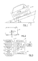
- FIG. 1 is a front view of a motor vehicle illustrating various operating parameters of a vehicle experiencing a turning manoeuvre on a banked road surface;
- FIG. 2 is a top view of a motor vehicle illustrating various operating parameters of a vehicle experiencing a turning manoeuvre on a banked road surface;
- FIG. 3 is a block diagram showing a portion of a microprocessor interconnected to sensors and controlled devices which may be included in a system according to the present invention;
- FIG 4 is a block diagrammatic view of the final roll angle determination according to the present invention; and
- FIG. 5 is a logic flow block diagram in accordance with the present invention.
-
- A method according to the present invention is intended for use with yaw control systems or rollover control systems which are typically implemented with electronically controlled hydraulically actuated or electrically actuated braking systems in automotive vehicles, however, the invention could easily be adapted for use in yaw control systems or rollover control systems on other motor vehicles, such as watercraft and aircraft as well as on other vehicle systems, such as active tilt or active suspension where it would be desirable to know the underlying road bank angle.
- Referring now to Figures 1 and 2, various operating parameters and variables used by the present invention are illustrated as they relate to the application of the present invention to a ground based
motor vehicle 10. Those skilled in the art will immediately recognize the basic physics represented by these illustrations, thereby make the adaptation to different types of vehicles easily within their reach. These parameters will be described in greater detail below. - Figure 3 illustrates the component parts of a
system 12 in which the present invention has been implemented successfully. Accordingly, acontroller 14 receives inputs from a steeringwheel angle sensor 16, ayaw sensor 18,wheel speed sensors 20, alateral acceleration sensor 22 and aroll rate sensor 24. Lateral acceleration, roll orientation and speed may be obtained using a global positioning system (GPS). Although not illustrated, other sensors and accelerometers could be employed in addition to, or as substitutes for those illustrated, depending upon the system being controlled and the available system sensor set while still making use of the present invention. As an example, the present invention could be carried out with equivalent operability and functionality using data to generate estimates of yaw rate and lateral acceleration if the cost, complexity or other considerations made it worthwhile to eliminate the actual sensors. -
Controller 14 is preferably microprocessor based. Those skilled in the art will appreciate in view of this disclosure that a processor within the controller and its associated peripheral equipment could be structured according to several different architectures. In a preferred embodiment, however, the processor is configured so that a control program is sequentially read for each unit command from a read-only memory (ROM) 26, which stores preset control programs. Unit commands are executed by a central processing unit (CPU) 28. The processor integrally includes an input-output control circuit (I/O) 30 for exchanging data with external devices and a random access memory (RAM) 32 for temporarily holding data while the data are being processed. -
Controller 14 may also be programmed with aspring mass model 34, which corresponds to the suspension of the automotive vehicle. The spring mass model varies for each type of vehicle and suspension configuration. Themodel 34 generates a predetermined output based upon the sensed conditions such as lateral acceleration. -
Controller 14 is coupled to asafety system 40. As previously noted, an exemplary application of the present invention includes a braking system having active yaw control or rollover control capability. For instance, a vehicle equipped with an active yaw control capable electronically controlled hydraulic braking system would include a hydraulic control unit operatively connected to brake actuators in cooperation with wheel and tire assemblies. The hydraulic control unit and brake actuators may be constructed in a known manner such as that commonly employed on Ford Motor vehicles equipped with ABS brakes in use today. - Those skilled in the art will appreciate in view of this disclosure that
wheel speed sensors 20 could comprise any of a variety of devices or systems employed in automotive vehicles for determining individual wheel speeds as well as a longitudinal velocity of the vehicle. One type of automotive speed sensor suitable for use with the present invention comprises a speed module for receiving input from multiple wheel speed sensors adapted to indicate the speed of the individual wheels. The speed module derives a longitudinal vehicle speed signal by combining the signals from the individual wheel speed sensors. One such type of speed signal module is embodied in brake control modules presently used in Ford Motor Company vehicles. The individual wheel speeds are ascertained using pulse generators disposed at each wheel. -
Roll rate sensor 24 may sense the roll condition of the vehicle based on sensing the height of one or more points on the vehicle relative to the road surface. Sensors that may be used to achieve this include a radar-based proximity sensor, a laser-based proximity sensor and a sonar-based proximity sensor.Roll rate sensor 24 may also sense the roll condition based on sensing the linear or rotational relative displacement or displacement velocity of one or more of the suspension chassis components which may include a linear height or travel sensor, a rotary height or travel sensor, a wheel speed sensor used to look for a change in velocity, a steering wheel position sensor, a steering wheel velocity sensor and a driver heading command input from an electronic component that may include steer by wire using a hand wheel or joy stick. The roll condition may also be sensed by sensing the force or torque associated with the loading condition of one or more suspension or chassis components including a pressure transducer in an act of suspension, a shock absorber sensor such as a load cell, a strain gauge, the steering system absolute or relative motor load, the steering system pressure of the hydraulic lines, a tire laterally force sensor or sensors, a longitudinal tire force sensor, a vertical tire force sensor or a tire sidewall torsion sensor. - The roll condition of the vehicle may also be established by one or more of the following translational or rotational positions, velocities or accelerations of the vehicle including a roll gyro, the
roll rate sensor 24, the yaw rate sensor, the lateral acceleration sensor, a vertical acceleration sensor, a vehicle longitudinal acceleration sensor, lateral or vertical speed sensor including a wheel-based speed sensor, a radar-based speed sensor, a sonar-based speed sensor, a laser-based speed sensor or an optical-based speed sensor. - Referring back now to Figures 1 and 2, the present invention determines an estimate of the vehicle roll angle, γ ν , which represents the sum of the vehicle tilt, due to suspension compliance, and a road bank angle, γ R . This is accomplished by using three separately derived roll angle estimates. One roll angle estimate is based on the roll rate signal, a second is based on the lateral acceleration and the spring mass model, and one based on a conservative road bank estimate. By compensating the roll angle estimate in this manner, the bank angle can be accurately estimated for most dynamic lateral conditions a vehicle will encounter in a controlled situation, improving the overall yaw control performance in common dynamic lateral events.
- Referring now to Figure 4, a model for determining the roll angle according to the present invention is shown. The model is preferably programmed within
controller 14.Controller 14, as mentioned above, determines three angles. The first angle is based upon the output ofroll rate sensor 24 as explained above. The output ofroll rate sensor 24 is coupled to anintegrator 42. The output ofintegrator 42 in turn is coupled to ahigh pass filter 44. By combiningintegrator 42 withhigh pass filter 44 drift issues are eliminated. By determining a roll angle based upon the roll rate, a high frequency vehicle roll angle is determined. The integration of the roll rate signal determines the roll angle. The output of thehigh pass filter 44 is coupled to a summingjunction 46. - The output of the
lateral acceleration sensor 22 of Figure 3 may also be used to determine a roll angle. The roll angle is based upon thespring mass model 34 shown in Figure 3 together with the lateral acceleration signal. The output of the suspension roll angle is coupled through alow pass filter 50. Preferably, the spring mass model has a single degree of freedom with the external lateral force excitation. The model provides the roll angle due to the difference in suspension deflection along the axial or lateral direction of the vehicle when subjected to a lateral force. The lateral force may be induced from either turning manoeuvres or from a gravity component due to the road bank. The roll angle determined is further fed into a low pass filter to obtain a low frequency component of vehicle roll angle. The roll angle determined by the spring and mass model is filtered bylow pass filter 50 and the resulting low frequency suspension roll angle is coupled to summingjunction 46. - In block 52 a first road bank angle estimate is obtained using the vehicle speed lateral acceleration sensor, yaw rate sensor, and steering wheel angle sensor shown in Figure 3. The first road bank estimate is obtained using the teachings described below or by any other convenient method. The first road bank angle estimate is coupled with the output from the spring mass model in
block 48 to obtain a conservative road bank estimate inblock 54. The "conservative" road bank estimate is referred to as conservative if the absolute value is smaller than that of the true road bank angle. That is, a road bank estimate is conservative if the estimate is closer to a flat or horizontal surface than the road's actual elevation. The first road bank angle estimate is reduced by the amount of the absolute value of the suspension roll if its absolute value has the same sign as the first road bank angle estimate. Further, adynamic factor block 56 may also be factored into the conservative road bank estimate. Thedynamic factor block 56 will be further described below. - The output of the conservative road
bank estimate block 54 is preferably low pass filtered inblock 58, which in turn is summed at summingjunction 46. - Summing
junction 46 sums the road bank estimate, the spring mass model roll angle, and the roll angle determined from the roll rate sensor to form a final roll angle inblock 60. Preferably, a simple addition of all the signals is performed. However, weighted sums could be used. - Referring now to Figure 5, the first road
bank estimate block 52 is described in further detail. Using equations of motion for a rigid body the following relationship can be obtained: - ay = lateral acceleration measured by an accelerometer on the vehicle;
- u = longitudinal velocity of vehicle;
- ω = yaw rate;
- ν ˙ = time derivative of the lateral velocity;
- g = gravitational constant; and
- γ ν = vehicle bank angle.
-
- From this, if we assume that the time derivative of the lateral velocity, ν ˙, is approximately zero, we can set
- We note that there will be error, primarily due to leaving ν ˙ out, however, the vehicle bank angle estimate, γ andν, will be valid when ν ˙ would otherwise be zero, e.g., lateral dynamics are steady state. This is what others have done, particularly the '658 reference.
- To provide greater accuracy in determining a bank angle estimate when the lateral dynamics are not steady state, the bias introduced by this assumption must be considered.
- At
block 70 the processor starts the illustrated logic flow block diagram when the operator keys on the vehicle ignition. The processor then moves to block 72 where parameters and operating conditions of the vehicle are updated from various sensors, where the various sensors are read and their data input to the processor. If this is the first time through the algorithm all of the variables are initialized with predetermined values. The processor then steps to block 74 where three unique estimates of the vehicle bank angle γ anda, γ andω and γ andν, are determined.
The first bank angle estimate, γ anda, is determined using measured or estimated lateral acceleration data according to the following relationship: - γ and a = a bank angle estimate based on measured lateral acceleration;
- A 1= a transfer function relating bank angle to vehicle
lateral acceleration, where:
- A 2= a transfer function relating steering wheel angle
to vehicle lateral acceleration, where:
- G= steering ratio relating actual tire angle, α, to steering wheel angle, δ;
- K= calibrated coefficient related to specific vehicle handling characteristics; and
- δ= steering wheel angle.
-
- The second bank angle estimate, γ andω, is determined using measured or estimated yaw rate data according to the following relationship:
- γ andω= bank angle estimate based on measured yaw rate;
- B 1= a transfer function relating bank angle to vehicle
yaw rate, where:
- B 2 = a transfer function relating steering
wheel angle to vehicle yaw rate, where:
-
- The third bank angle estimate, γ and ν , is determined using measured or estimated lateral acceleration and yaw rate data in a rearranged version of Equation (2) from above, as follows:where:

- γ andν= vehicle bank angle estimate based on measured lateral acceleration and yaw rate data based on the simplified equation of motion.
-
- Once the processor has the three estimates from above, it proceeds to block 76 and calculates the bank angle bias due to the lateral dynamics. The processor determines the bias by the following equation:
- DNCF= a dynamics compensation factor, which is
generally a function of the three estimates and the
longitudinal velocity, which may take the following form:
-
- The processor then proceeds to block 78 where bias is used to account for the error introduced from simplifying Equation (1) into Equation (2). Together, DNCF and
- In
step 78, the frequencies of the third bank angle estimate are decomposed into a plurality of frequency bands. The number of bands depends on many things including the desired accuracy and system to which it is applied. In one constructed embodiment, three frequency bands were used. - In
step 80, the DNCF is filtered to obtain a frequency band dynamic compensation factor corresponding to each of the frequency bands of the third bank angle determined instep 78. The decomposed frequency bank angles of each band are subject to a reduction instep 82 based on a multiplicative factor between zero and 1 that is a function of the dynamic compensation factor. The multiplicative factor in each band is chosen to remove bias in that band. - The filtering of step 68 may, for example, be low pass filtering selected for the frequency ranges of decomposition performed in
step 78. Thestep 82 may further comprise the determination and use of the rate of change for the third bank angle estimate, ϑ ν - In
step 84, the frequency band reductions ofstep 82 are summed together instep 84 to form a final road bank angle estimate. By performing a reduction based on the dynamic compensation factor, a more accurate estimation of road bank angle may be determined. Such a determination is believed to be extremely useful in manoeuvres even on snow and ice while avoiding false or nuisance activation on a banked road. - The processor then proceeds to block 84 and outputs the final bank angle estimate to the
controller 14 so that adjustments can be made in the control calculations. Finally, the processor returns throughblock 86 to block 72, where it will repeat the bank angle estimation process until the vehicle ignition is turned off. - Various modifications will no doubt occur to those skilled in the arts to which this invention pertains. For example, the particular sensors used in conjunction with the disclosed method may be varied from those herein, as there are numerous possible methods for measuring or estimating the longitudinal velocity, yaw rate and lateral acceleration of a vehicle. Additionally, the method may be practiced with significant changes to the various transfer functions described above while remaining within the calculation and logic flow scheme described herein. Finally, it should be noted that if one desires an estimate of the lateral dynamics of Equation (1), it can be calculated using the final bank angle estimate.
- It will be appreciated that these and other variations are properly considered within the scope of this invention.
Claims (10)
- A system (12) for controlling a vehicle (10) characterised in that the system (12) comprises a lateral acceleration sensor (22) generating a lateral acceleration signal corresponding to a lateral acceleration of the vehicle (10), a yaw rate sensor (18) generating a yaw rate signal corresponding to a yaw rate of the vehicle (10), a steering wheel angle sensor (16) generating a steering wheel angle signal corresponding to a steering wheel angle of the vehicle (10), a speed sensor (20) generating a speed signal corresponding to the longitudinal speed of the vehicle (10), a roll rate sensor (24) generating a roll rate signal and a controller (14) coupled to the lateral acceleration sensor (22), the yaw rate sensor (18), the steering wheel angle sensor (16) and the speed sensor (20) wherein the controller (14) is operable to calculate a first roll angle signal in response to the roll rate signal, to calculate a bank angle signal in response to the lateral acceleration, the yaw rate, the steering wheel and the speed signals, and is further operable to sum the first roll angle signal and the bank angle signal to obtain a final roll angle estimate.
- A system as claimed in claim 1 further comprising a high pass filter (44) filtering the first roll angle signal.
- A system as claimed in claim 1 or in claim 2 wherein the controller (14) calculates a second roll angle signal corresponding to a suspension reference roll angle in response to the lateral acceleration signal and sums the first roll angle signal, the second roll angle signal and the bank angle signal to obtain a final roll angle estimate.
- A system as claimed in claim 3 further comprising a first low pass filter (50) to filter the second roll angle signal.
- A system as claimed in any of claims 1 to 4 further comprising a bank angle filter (58) to filter the bank angle signal.
- A system as claimed in any of claims 1 to 5 wherein the controller (14) further comprises an integrator (42) to integrate the roll rate signal to obtain the first roll angle signal.
- A system as claimed in claim 1 wherein the controller (14) is operable to calculate a first bank angle estimate dependent on the lateral acceleration signal, calculate a second bank angle estimate dependent on the yaw rate signal, calculate a third bank angle estimate dependent on both the lateral acceleration signal and the second yaw rate signal, calculate a dynamic compensation factor based upon a function of the first bank angle estimate, the second bank angle estimate and the third bank angle estimate, decompose the third bank angle estimate into a plurality of third bank angle frequency bands, reduce each of the plurality of third bank angle frequency bands in response to a multiplicative factor, the multiplicative factor being a function of the dynamic compensation factor to obtain a plurality of reduced third bank angles, and calculate a final bank angle bias estimate based on a sum of the plurality of reduced third bank angles.
- A method of determining a roll angle of a vehicle characterised in that the method comprises providing a lateral acceleration signal corresponding to a lateral acceleration of the vehicle (10), providing a yaw rate signal corresponding to a yaw rate of the vehicle (10), providing a steering wheel signal responsive to a sensed steering wheel angle of the vehicle (10), providing a speed signal corresponding to a vehicle speed, calculating a first bank angle estimate dependent on the lateral acceleration signal, the yaw rate signal, the steering wheel signal and the speed signal, calculating a suspension reference roll angle in response to the lateral acceleration signal and calculating a conservative bank angle estimate signal in response to the first bank angle estimate and the suspension roll reference angle.
- A method as claimed in claim 8 further comprising providing a roll rate signal corresponding to the roll rate of the vehicle, integrating the roll rate signal to obtain a roll-rate based roll angle and summing the conservative bank angle estimate, the suspension reference roll angle and the roll-rate based roll angle to obtain a final roll angle estimate.
- A method as claimed in claim 8 wherein calculating a first bank angle estimate comprises calculating a first bank angle estimate dependent on the lateral acceleration signal and the method further comprises calculating a second bank angle estimate dependent on the yaw rate signal, calculating a third bank angle estimate dependent on both the lateral acceleration signal and the yaw rate signal, calculating a dynamic compensation factor based as a function of the first bank angle estimate, the second bank angle estimate and the third bank angle estimate, decomposing the third bank angle estimate into a plurality of third bank angle frequency bands, reducing each of the plurality of third bank angle frequency bands in response to a multiplicative factor, the multiplicative factor being a function of the dynamic compensation factor to obtain a plurality of reduced third bank angles and calculating a final bank angle bias estimate based on a sum of the plurality of reduced third bank angles.
Applications Claiming Priority (2)
| Application Number | Priority Date | Filing Date | Title |
|---|---|---|---|
| US101998 | 2002-03-20 | ||
| US10/101,998 US6804584B2 (en) | 2002-03-20 | 2002-03-20 | Method for determining the roll angle of a vehicle using an estimation of road bank angle |
Publications (3)
| Publication Number | Publication Date |
|---|---|
| EP1346856A2 true EP1346856A2 (en) | 2003-09-24 |
| EP1346856A3 EP1346856A3 (en) | 2004-12-08 |
| EP1346856B1 EP1346856B1 (en) | 2009-09-30 |
Family
ID=27788352
Family Applications (1)
| Application Number | Title | Priority Date | Filing Date |
|---|---|---|---|
| EP03100122A Expired - Fee Related EP1346856B1 (en) | 2002-03-20 | 2003-01-21 | A system and method for determining the roll angle of a vehicle |
Country Status (3)
| Country | Link |
|---|---|
| US (1) | US6804584B2 (en) |
| EP (1) | EP1346856B1 (en) |
| DE (1) | DE60329432D1 (en) |
Cited By (13)
| Publication number | Priority date | Publication date | Assignee | Title |
|---|---|---|---|---|
| EP1386801A1 (en) * | 2002-08-01 | 2004-02-04 | Ford Global Technologies, LLC | System and method for characterizing the road bank for vehicle roll stability control |
| WO2005105485A1 (en) * | 2004-04-10 | 2005-11-10 | Daimlerchrysler Ag | Device for determining the roll angle and system and method for roll stabilisation of a motor vehicle |
| WO2007003858A2 (en) | 2005-07-05 | 2007-01-11 | Renault S.A.S. | Anti-rolling method and system for a vehicle and corresponding vehicle |
| EP1880875A2 (en) | 2006-07-20 | 2008-01-23 | Sumitomo Rubber Industries, Ltd. | Method, apparatus and program for alarming decrease in tire air-pressure |
| EP2127989A1 (en) * | 2008-05-28 | 2009-12-02 | Delphi Technologies, Inc. | Dynamic-based method of estimating the absolute roll angle of a vehicle body |
| EP2127988A1 (en) * | 2008-05-28 | 2009-12-02 | Delphi Technologies, Inc. | Kinematic-based method of estimating the absolute roll angle of a vehicle body |
| CN101786454A (en) * | 2010-02-03 | 2010-07-28 | 无锡市亦清轩数码动漫设计有限公司 | Automatic safety control system of electric vehicle and control method thereof |
| KR20110088095A (en) * | 2010-01-28 | 2011-08-03 | 현대모비스 주식회사 | Detecting method of bank-road |
| AT505363B1 (en) * | 2007-06-14 | 2013-02-15 | Zizala Lichtsysteme Gmbh | METHOD AND MEASURING ARRANGEMENT FOR DETERMINING THE ROLLER ANGLE OF A UNILATED MOTOR VEHICLE |
| WO2014094933A1 (en) * | 2012-12-20 | 2014-06-26 | Daimler Ag | Method for combined determining of a momentary roll angle of a motor vehicle and a momentary roadway cross slope of a curved roadway section traveled by the motor vehicle |
| EP2481651A4 (en) * | 2009-09-24 | 2016-10-19 | Toyota Motor Co Ltd | Device for estimating turning characteristic of vehicle |
| CN107804315A (en) * | 2017-11-07 | 2018-03-16 | 吉林大学 | It is a kind of to consider to drive people's car collaboration rotating direction control method that power is distributed in real time |
| CN110843766A (en) * | 2019-10-31 | 2020-02-28 | 泰斗微电子科技有限公司 | Vehicle attitude detection method, device, vehicle-mounted terminal, vehicle and medium |
Families Citing this family (30)
| Publication number | Priority date | Publication date | Assignee | Title |
|---|---|---|---|---|
| US6961648B2 (en) * | 2002-08-05 | 2005-11-01 | Ford Motor Company | System and method for desensitizing the activation criteria of a rollover control system |
| US6856868B1 (en) * | 2003-10-24 | 2005-02-15 | Ford Global Technologies, Llc | Kinetic energy density rollover detective sensing algorithm |
| US7593798B2 (en) * | 2003-10-30 | 2009-09-22 | Deere & Company | Vehicular guidance system having compensation for variations in ground elevation |
| JP4558395B2 (en) * | 2004-07-12 | 2010-10-06 | 富士重工業株式会社 | Wheel contact state determination device, wheel contact state determination method, and vehicle motion control device |
| US7826948B2 (en) * | 2004-10-15 | 2010-11-02 | Ford Global Technologies | Vehicle loading based vehicle dynamic and safety related characteristic adjusting system |
| US7668645B2 (en) | 2004-10-15 | 2010-02-23 | Ford Global Technologies | System and method for dynamically determining vehicle loading and vertical loading distance for use in a vehicle dynamic control system |
| US7715965B2 (en) * | 2004-10-15 | 2010-05-11 | Ford Global Technologies | System and method for qualitatively determining vehicle loading conditions |
| US7660654B2 (en) | 2004-12-13 | 2010-02-09 | Ford Global Technologies, Llc | System for dynamically determining vehicle rear/trunk loading for use in a vehicle control system |
| US7590481B2 (en) | 2005-09-19 | 2009-09-15 | Ford Global Technologies, Llc | Integrated vehicle control system using dynamically determined vehicle conditions |
| US8121758B2 (en) | 2005-11-09 | 2012-02-21 | Ford Global Technologies | System for determining torque and tire forces using integrated sensing system |
| US7600826B2 (en) | 2005-11-09 | 2009-10-13 | Ford Global Technologies, Llc | System for dynamically determining axle loadings of a moving vehicle using integrated sensing system and its application in vehicle dynamics controls |
| US7788007B2 (en) * | 2006-01-12 | 2010-08-31 | Gm Global Technology Operations, Inc. | Roll stability indicator for vehicle rollover control |
| US7571030B2 (en) * | 2006-04-10 | 2009-08-04 | Gm Global Technology Operations, Inc. | Estimation of vehicle roll rate and roll angle using suspension deflection sensors |
| US7884772B2 (en) * | 2007-05-07 | 2011-02-08 | Lockheed Martin Corporation | Radar apparatus and alignment sensor |
| US20090319186A1 (en) * | 2008-06-24 | 2009-12-24 | Honeywell International Inc. | Method and apparatus for determining a navigational state of a vehicle |
| TWI337585B (en) * | 2008-10-16 | 2011-02-21 | Univ Nat Chiao Tung | Road angle estimation system and its method |
| US8326494B2 (en) * | 2008-10-24 | 2012-12-04 | GM Global Technology Operations LLC | Method and apparatus for determining a desired yaw rate for a vehicle |
| US9260096B2 (en) * | 2011-02-22 | 2016-02-16 | Nissin Kogyo Co., Ltd. | Brake fluid pressure control apparatus for vehicle |
| US9187119B2 (en) | 2011-12-14 | 2015-11-17 | Steering Solutions Ip Holding Corporation | Wheel speed velocity variation scaling system |
| WO2013121022A1 (en) * | 2012-02-15 | 2013-08-22 | Floor Master | System for reducing roll and pitch in a moving vehicle |
| GB2510417B (en) * | 2013-02-04 | 2016-06-15 | Jaguar Land Rover Ltd | Method and system of angle estimation |
| KR101642468B1 (en) * | 2014-08-08 | 2016-07-28 | 코리아테스팅 주식회사 | Weight Balancing Type Dynamic Yawing Simulator |
| GB2536008B (en) * | 2015-03-03 | 2019-06-12 | Jaguar Land Rover Ltd | Vehicle state estimation apparatus and method |
| JP6380468B2 (en) * | 2016-06-21 | 2018-08-29 | マツダ株式会社 | Four-wheel drive vehicle control system |
| US10569651B2 (en) * | 2017-05-15 | 2020-02-25 | Baidu Usa Llc | Speed control and steering control assistant based on pitch status and roll status of autonomous driving vehicle |
| US10836386B2 (en) * | 2017-11-10 | 2020-11-17 | GM Global Technology Operations LLC | Determination of roll angle and bank angle with suspension displacement data |
| CN108297872B (en) * | 2018-03-08 | 2023-05-05 | 中国第一汽车股份有限公司 | Full-working-condition vehicle-mounted road gradient estimation device and method |
| JP7087564B2 (en) * | 2018-03-29 | 2022-06-21 | トヨタ自動車株式会社 | Kant estimation method |
| DE102019003238B4 (en) * | 2019-05-08 | 2023-04-20 | Mercedes-Benz Group AG | Vehicle location by map comparison taking into account a street profile |
| US11921160B2 (en) * | 2022-06-07 | 2024-03-05 | Synopsys, Inc. | Using scan chains to read out data from integrated sensors during scan tests |
Citations (4)
| Publication number | Priority date | Publication date | Assignee | Title |
|---|---|---|---|---|
| US5446658A (en) | 1994-06-22 | 1995-08-29 | General Motors Corporation | Method and apparatus for estimating incline and bank angles of a road surface |
| US6038495A (en) | 1998-02-06 | 2000-03-14 | Delco Electronics Corporation | Vehicle rollover sensing using short-term integration |
| US6073065A (en) | 1998-09-04 | 2000-06-06 | Ford Global Technologies, Inc. | Method for detecting a bank angle experienced by a moving vehicle |
| US6212455B1 (en) | 1998-12-03 | 2001-04-03 | Indiana Mills & Manufacturing, Inc. | Roll sensor system for a vehicle |
Family Cites Families (15)
| Publication number | Priority date | Publication date | Assignee | Title |
|---|---|---|---|---|
| SE441039B (en) | 1983-12-08 | 1985-09-02 | Gote Palsgard | DEVICE FOR SATURING THE SIDE SLEEP OF A SUBSTRATE WITH A SHARPABLE TRANSFERABLE WAGON |
| JPH0396468A (en) | 1989-09-07 | 1991-04-22 | Honda Motor Co Ltd | Estimation method for fore and aft acceleration and deceleration of body |
| DE19507957C1 (en) | 1995-03-07 | 1996-09-12 | Daimler Benz Ag | Vehicle with optical scanning device for a side lane area |
| US5742919A (en) | 1996-04-26 | 1998-04-21 | Ford Global Technologies, Inc. | Method and apparatus for dynamically determining a lateral velocity of a motor vehicle |
| US5720533A (en) | 1996-10-15 | 1998-02-24 | General Motors Corporation | Brake control system |
| US5723782A (en) | 1996-11-29 | 1998-03-03 | Bolles, Jr.; Robert C. | Method of land vehicle suspension evaluation and design through roll angle analysis |
| DE19812237C1 (en) | 1998-03-20 | 1999-09-23 | Daimler Chrysler Ag | Method for driving dynamics control on a road vehicle |
| DE19821617C1 (en) * | 1998-05-15 | 1999-09-30 | Daimler Chrysler Ag | Inclination angle measuring method for stability regulation during automobile cornering |
| US6292759B1 (en) * | 1998-11-19 | 2001-09-18 | Delphi Technologies, Inc. | Vehicle attitude angle estimation using sensed signal blending |
| US6195606B1 (en) | 1998-12-07 | 2001-02-27 | General Motors Corporation | Vehicle active brake control with bank angle compensation |
| US6202009B1 (en) * | 1998-12-22 | 2001-03-13 | Ford Global Technologies, Inc. | Method for detecting fault of vehicle motion sensors |
| JP3736999B2 (en) * | 1999-09-06 | 2006-01-18 | 本田技研工業株式会社 | Vehicle rollover judgment method |
| JP2003517151A (en) * | 1999-12-16 | 2003-05-20 | シーメンス アクチエンゲゼルシヤフト | Method and apparatus for determining an absolute angle of rotation of an object rotating about a substantially horizontal axis of rotation |
| US6351694B1 (en) * | 2001-01-16 | 2002-02-26 | Ford Global Technologies, Inc. | Method for robust estimation of road bank angle |
| US7107136B2 (en) * | 2001-08-29 | 2006-09-12 | Delphi Technologies, Inc. | Vehicle rollover detection and mitigation using rollover index |
-
2002
- 2002-03-20 US US10/101,998 patent/US6804584B2/en not_active Expired - Fee Related
-
2003
- 2003-01-21 DE DE60329432T patent/DE60329432D1/en not_active Expired - Lifetime
- 2003-01-21 EP EP03100122A patent/EP1346856B1/en not_active Expired - Fee Related
Patent Citations (4)
| Publication number | Priority date | Publication date | Assignee | Title |
|---|---|---|---|---|
| US5446658A (en) | 1994-06-22 | 1995-08-29 | General Motors Corporation | Method and apparatus for estimating incline and bank angles of a road surface |
| US6038495A (en) | 1998-02-06 | 2000-03-14 | Delco Electronics Corporation | Vehicle rollover sensing using short-term integration |
| US6073065A (en) | 1998-09-04 | 2000-06-06 | Ford Global Technologies, Inc. | Method for detecting a bank angle experienced by a moving vehicle |
| US6212455B1 (en) | 1998-12-03 | 2001-04-03 | Indiana Mills & Manufacturing, Inc. | Roll sensor system for a vehicle |
Non-Patent Citations (1)
| Title |
|---|
| Y.FUKADA: "Estimation of Vehicle Slip-Angle With Combination Method of Model Observer and Direct Integration.", INTERNATIONAL SYMPOSIUM ON ADVANCE VEHICLE CONTROL, 10 September 1998 (1998-09-10) - September 1998 (1998-09-01) |
Cited By (20)
| Publication number | Priority date | Publication date | Assignee | Title |
|---|---|---|---|---|
| EP1386801A1 (en) * | 2002-08-01 | 2004-02-04 | Ford Global Technologies, LLC | System and method for characterizing the road bank for vehicle roll stability control |
| WO2005105485A1 (en) * | 2004-04-10 | 2005-11-10 | Daimlerchrysler Ag | Device for determining the roll angle and system and method for roll stabilisation of a motor vehicle |
| WO2007003858A2 (en) | 2005-07-05 | 2007-01-11 | Renault S.A.S. | Anti-rolling method and system for a vehicle and corresponding vehicle |
| FR2888165A1 (en) * | 2005-07-05 | 2007-01-12 | Renault Sas | METHOD AND SYSTEM FOR ANTI-ROLLING A VEHICLE AND VEHICLE THEREFOR |
| WO2007003858A3 (en) * | 2005-07-05 | 2007-06-21 | Renault Sa | Anti-rolling method and system for a vehicle and corresponding vehicle |
| EP1880875A3 (en) * | 2006-07-20 | 2011-10-12 | Sumitomo Rubber Industries, Ltd. | Method, apparatus and program for alarming decrease in tire air-pressure |
| EP1880875A2 (en) | 2006-07-20 | 2008-01-23 | Sumitomo Rubber Industries, Ltd. | Method, apparatus and program for alarming decrease in tire air-pressure |
| AT505363B1 (en) * | 2007-06-14 | 2013-02-15 | Zizala Lichtsysteme Gmbh | METHOD AND MEASURING ARRANGEMENT FOR DETERMINING THE ROLLER ANGLE OF A UNILATED MOTOR VEHICLE |
| EP2127988A1 (en) * | 2008-05-28 | 2009-12-02 | Delphi Technologies, Inc. | Kinematic-based method of estimating the absolute roll angle of a vehicle body |
| EP2127989A1 (en) * | 2008-05-28 | 2009-12-02 | Delphi Technologies, Inc. | Dynamic-based method of estimating the absolute roll angle of a vehicle body |
| EP2481651A4 (en) * | 2009-09-24 | 2016-10-19 | Toyota Motor Co Ltd | Device for estimating turning characteristic of vehicle |
| KR20110088095A (en) * | 2010-01-28 | 2011-08-03 | 현대모비스 주식회사 | Detecting method of bank-road |
| CN101786454A (en) * | 2010-02-03 | 2010-07-28 | 无锡市亦清轩数码动漫设计有限公司 | Automatic safety control system of electric vehicle and control method thereof |
| WO2014094933A1 (en) * | 2012-12-20 | 2014-06-26 | Daimler Ag | Method for combined determining of a momentary roll angle of a motor vehicle and a momentary roadway cross slope of a curved roadway section traveled by the motor vehicle |
| CN104853941A (en) * | 2012-12-20 | 2015-08-19 | 戴姆勒股份公司 | Method for combined determining of a momentary roll angle of a motor vehicle and a momentary roadway cross slope of a curved roadway section traveled by the motor vehicle |
| US9849886B2 (en) | 2012-12-20 | 2017-12-26 | Daimler Ag | Method for combined determining of a momentary roll angle of a motor vehicle and a momentary roadway cross slope of a curved roadway section traveled by the motor vehicle |
| CN107804315A (en) * | 2017-11-07 | 2018-03-16 | 吉林大学 | It is a kind of to consider to drive people's car collaboration rotating direction control method that power is distributed in real time |
| CN107804315B (en) * | 2017-11-07 | 2019-07-16 | 吉林大学 | It is a kind of to consider to drive people's vehicle collaboration rotating direction control method that power is distributed in real time |
| CN110843766A (en) * | 2019-10-31 | 2020-02-28 | 泰斗微电子科技有限公司 | Vehicle attitude detection method, device, vehicle-mounted terminal, vehicle and medium |
| CN110843766B (en) * | 2019-10-31 | 2021-07-13 | 泰斗微电子科技有限公司 | Vehicle attitude detection method, device, vehicle-mounted terminal, vehicle and medium |
Also Published As
| Publication number | Publication date |
|---|---|
| EP1346856A3 (en) | 2004-12-08 |
| US20030182025A1 (en) | 2003-09-25 |
| US6804584B2 (en) | 2004-10-12 |
| EP1346856B1 (en) | 2009-09-30 |
| DE60329432D1 (en) | 2009-11-12 |
Similar Documents
| Publication | Publication Date | Title |
|---|---|---|
| EP1346856B1 (en) | A system and method for determining the roll angle of a vehicle | |
| US6631317B2 (en) | Attitude sensing system for an automotive vehicle | |
| US6684140B2 (en) | System for sensing vehicle global and relative attitudes using suspension height sensors | |
| US6351694B1 (en) | Method for robust estimation of road bank angle | |
| US6714851B2 (en) | Method for road grade/vehicle pitch estimation | |
| EP1479581B1 (en) | An integrated sensing system for an automotive system | |
| US6556908B1 (en) | Attitude sensing system for an automotive vehicle relative to the road | |
| US6671595B2 (en) | Vehicle side slip angle estimation using dynamic blending and considering vehicle attitude information | |
| US7222007B2 (en) | Attitude sensing system for an automotive vehicle relative to the road | |
| EP0983919B1 (en) | A method for detecting a bank angle experienced by a moving vehicle | |
| US7010409B2 (en) | Reference signal generator for an integrated sensing system | |
| US7079928B2 (en) | System and method for determining a wheel departure angle for a rollover control system with respect to road roll rate and loading misalignment | |
| US6718248B2 (en) | System for detecting surface profile of a driving road | |
| US7480547B2 (en) | Attitude sensing system for an automotive vehicle relative to the road | |
| US7451032B2 (en) | System and method for determining desired yaw rate and lateral velocity for use in a vehicle dynamic control system | |
| US6725140B2 (en) | Method and apparatus for determining lateral velocity of a motor vehicle in closed form for all road and driving conditions | |
| US20070106442A1 (en) | System for dynamically determining axle loadings of a moving vehicle using integrated sensing system and its application in vehicle dynamics controls | |
| US20020082749A1 (en) | Roll over stability control for an automotive vehicle having rear wheel steering | |
| US20030100979A1 (en) | Enhanced system for yaw stability control system to include roll stability control function | |
| EP1386807B1 (en) | System and method for determining a wheel departure angle for a rollover control system | |
| EP1386808B1 (en) | System and method for characterizing vehicle body to road angle for vehicle roll stability control | |
| EP1386801B1 (en) | System and method for characterizing the road bank for vehicle roll stability control |
Legal Events
| Date | Code | Title | Description |
|---|---|---|---|
| PUAI | Public reference made under article 153(3) epc to a published international application that has entered the european phase |
Free format text: ORIGINAL CODE: 0009012 |
|
| AK | Designated contracting states |
Kind code of ref document: A2 Designated state(s): AT BE BG CH CY CZ DE DK EE ES FI FR GB GR HU IE IT LI LU MC NL PT SE SI SK TR |
|
| AX | Request for extension of the european patent |
Extension state: AL LT LV MK RO |
|
| PUAL | Search report despatched |
Free format text: ORIGINAL CODE: 0009013 |
|
| AK | Designated contracting states |
Kind code of ref document: A3 Designated state(s): AT BE BG CH CY CZ DE DK EE ES FI FR GB GR HU IE IT LI LU MC NL PT SE SI SK TR |
|
| AX | Request for extension of the european patent |
Extension state: AL LT LV MK RO |
|
| 17P | Request for examination filed |
Effective date: 20050502 |
|
| AKX | Designation fees paid |
Designated state(s): DE FR GB |
|
| GRAP | Despatch of communication of intention to grant a patent |
Free format text: ORIGINAL CODE: EPIDOSNIGR1 |
|
| GRAS | Grant fee paid |
Free format text: ORIGINAL CODE: EPIDOSNIGR3 |
|
| GRAA | (expected) grant |
Free format text: ORIGINAL CODE: 0009210 |
|
| AK | Designated contracting states |
Kind code of ref document: B1 Designated state(s): DE FR GB |
|
| REG | Reference to a national code |
Ref country code: GB Ref legal event code: FG4D |
|
| REF | Corresponds to: |
Ref document number: 60329432 Country of ref document: DE Date of ref document: 20091112 Kind code of ref document: P |
|
| PLBE | No opposition filed within time limit |
Free format text: ORIGINAL CODE: 0009261 |
|
| STAA | Information on the status of an ep patent application or granted ep patent |
Free format text: STATUS: NO OPPOSITION FILED WITHIN TIME LIMIT |
|
| 26N | No opposition filed |
Effective date: 20100701 |
|
| REG | Reference to a national code |
Ref country code: FR Ref legal event code: PLFP Year of fee payment: 14 |
|
| PGFP | Annual fee paid to national office [announced via postgrant information from national office to epo] |
Ref country code: GB Payment date: 20151230 Year of fee payment: 14 |
|
| PGFP | Annual fee paid to national office [announced via postgrant information from national office to epo] |
Ref country code: DE Payment date: 20160127 Year of fee payment: 14 |
|
| PGFP | Annual fee paid to national office [announced via postgrant information from national office to epo] |
Ref country code: FR Payment date: 20151230 Year of fee payment: 14 |
|
| REG | Reference to a national code |
Ref country code: DE Ref legal event code: R119 Ref document number: 60329432 Country of ref document: DE |
|
| GBPC | Gb: european patent ceased through non-payment of renewal fee |
Effective date: 20170121 |
|
| REG | Reference to a national code |
Ref country code: FR Ref legal event code: ST Effective date: 20170929 |
|
| PG25 | Lapsed in a contracting state [announced via postgrant information from national office to epo] |
Ref country code: FR Free format text: LAPSE BECAUSE OF NON-PAYMENT OF DUE FEES Effective date: 20170131 |
|
| PG25 | Lapsed in a contracting state [announced via postgrant information from national office to epo] |
Ref country code: DE Free format text: LAPSE BECAUSE OF NON-PAYMENT OF DUE FEES Effective date: 20170801 Ref country code: GB Free format text: LAPSE BECAUSE OF NON-PAYMENT OF DUE FEES Effective date: 20170121 |