EP1342609A1 - Steering mechanism of electric car - Google Patents
Steering mechanism of electric car Download PDFInfo
- Publication number
- EP1342609A1 EP1342609A1 EP01980915A EP01980915A EP1342609A1 EP 1342609 A1 EP1342609 A1 EP 1342609A1 EP 01980915 A EP01980915 A EP 01980915A EP 01980915 A EP01980915 A EP 01980915A EP 1342609 A1 EP1342609 A1 EP 1342609A1
- Authority
- EP
- European Patent Office
- Prior art keywords
- steering
- wheel
- wheels
- motor
- car
- Prior art date
- Legal status (The legal status is an assumption and is not a legal conclusion. Google has not performed a legal analysis and makes no representation as to the accuracy of the status listed.)
- Granted
Links
Images


Classifications
-
- B—PERFORMING OPERATIONS; TRANSPORTING
- B62—LAND VEHICLES FOR TRAVELLING OTHERWISE THAN ON RAILS
- B62D—MOTOR VEHICLES; TRAILERS
- B62D7/00—Steering linkage; Stub axles or their mountings
- B62D7/06—Steering linkage; Stub axles or their mountings for individually-pivoted wheels, e.g. on king-pins
- B62D7/14—Steering linkage; Stub axles or their mountings for individually-pivoted wheels, e.g. on king-pins the pivotal axes being situated in more than one plane transverse to the longitudinal centre line of the vehicle, e.g. all-wheel steering
- B62D7/15—Steering linkage; Stub axles or their mountings for individually-pivoted wheels, e.g. on king-pins the pivotal axes being situated in more than one plane transverse to the longitudinal centre line of the vehicle, e.g. all-wheel steering characterised by means varying the ratio between the steering angles of the steered wheels
- B62D7/159—Steering linkage; Stub axles or their mountings for individually-pivoted wheels, e.g. on king-pins the pivotal axes being situated in more than one plane transverse to the longitudinal centre line of the vehicle, e.g. all-wheel steering characterised by means varying the ratio between the steering angles of the steered wheels characterised by computing methods or stabilisation processes or systems, e.g. responding to yaw rate, lateral wind, load, road condition
-
- B—PERFORMING OPERATIONS; TRANSPORTING
- B60—VEHICLES IN GENERAL
- B60L—PROPULSION OF ELECTRICALLY-PROPELLED VEHICLES; SUPPLYING ELECTRIC POWER FOR AUXILIARY EQUIPMENT OF ELECTRICALLY-PROPELLED VEHICLES; ELECTRODYNAMIC BRAKE SYSTEMS FOR VEHICLES IN GENERAL; MAGNETIC SUSPENSION OR LEVITATION FOR VEHICLES; MONITORING OPERATING VARIABLES OF ELECTRICALLY-PROPELLED VEHICLES; ELECTRIC SAFETY DEVICES FOR ELECTRICALLY-PROPELLED VEHICLES
- B60L15/00—Methods, circuits, or devices for controlling the traction-motor speed of electrically-propelled vehicles
- B60L15/20—Methods, circuits, or devices for controlling the traction-motor speed of electrically-propelled vehicles for control of the vehicle or its driving motor to achieve a desired performance, e.g. speed, torque, programmed variation of speed
- B60L15/2036—Electric differentials, e.g. for supporting steering vehicles
-
- B—PERFORMING OPERATIONS; TRANSPORTING
- B60—VEHICLES IN GENERAL
- B60W—CONJOINT CONTROL OF VEHICLE SUB-UNITS OF DIFFERENT TYPE OR DIFFERENT FUNCTION; CONTROL SYSTEMS SPECIALLY ADAPTED FOR HYBRID VEHICLES; ROAD VEHICLE DRIVE CONTROL SYSTEMS FOR PURPOSES NOT RELATED TO THE CONTROL OF A PARTICULAR SUB-UNIT
- B60W30/00—Purposes of road vehicle drive control systems not related to the control of a particular sub-unit, e.g. of systems using conjoint control of vehicle sub-units, or advanced driver assistance systems for ensuring comfort, stability and safety or drive control systems for propelling or retarding the vehicle
- B60W30/18—Propelling the vehicle
- B60W30/18009—Propelling the vehicle related to particular drive situations
- B60W30/18145—Cornering
-
- B—PERFORMING OPERATIONS; TRANSPORTING
- B62—LAND VEHICLES FOR TRAVELLING OTHERWISE THAN ON RAILS
- B62D—MOTOR VEHICLES; TRAILERS
- B62D7/00—Steering linkage; Stub axles or their mountings
- B62D7/06—Steering linkage; Stub axles or their mountings for individually-pivoted wheels, e.g. on king-pins
- B62D7/14—Steering linkage; Stub axles or their mountings for individually-pivoted wheels, e.g. on king-pins the pivotal axes being situated in more than one plane transverse to the longitudinal centre line of the vehicle, e.g. all-wheel steering
- B62D7/142—Steering linkage; Stub axles or their mountings for individually-pivoted wheels, e.g. on king-pins the pivotal axes being situated in more than one plane transverse to the longitudinal centre line of the vehicle, e.g. all-wheel steering specially adapted for particular vehicles, e.g. tractors, carts, earth-moving vehicles, trucks
- B62D7/144—Steering linkage; Stub axles or their mountings for individually-pivoted wheels, e.g. on king-pins the pivotal axes being situated in more than one plane transverse to the longitudinal centre line of the vehicle, e.g. all-wheel steering specially adapted for particular vehicles, e.g. tractors, carts, earth-moving vehicles, trucks for vehicles with more than two axles
-
- B—PERFORMING OPERATIONS; TRANSPORTING
- B62—LAND VEHICLES FOR TRAVELLING OTHERWISE THAN ON RAILS
- B62D—MOTOR VEHICLES; TRAILERS
- B62D7/00—Steering linkage; Stub axles or their mountings
- B62D7/06—Steering linkage; Stub axles or their mountings for individually-pivoted wheels, e.g. on king-pins
- B62D7/14—Steering linkage; Stub axles or their mountings for individually-pivoted wheels, e.g. on king-pins the pivotal axes being situated in more than one plane transverse to the longitudinal centre line of the vehicle, e.g. all-wheel steering
- B62D7/15—Steering linkage; Stub axles or their mountings for individually-pivoted wheels, e.g. on king-pins the pivotal axes being situated in more than one plane transverse to the longitudinal centre line of the vehicle, e.g. all-wheel steering characterised by means varying the ratio between the steering angles of the steered wheels
- B62D7/1581—Steering linkage; Stub axles or their mountings for individually-pivoted wheels, e.g. on king-pins the pivotal axes being situated in more than one plane transverse to the longitudinal centre line of the vehicle, e.g. all-wheel steering characterised by means varying the ratio between the steering angles of the steered wheels characterised by comprising an electrical interconnecting system between the steering control means of the different axles
-
- B—PERFORMING OPERATIONS; TRANSPORTING
- B60—VEHICLES IN GENERAL
- B60K—ARRANGEMENT OR MOUNTING OF PROPULSION UNITS OR OF TRANSMISSIONS IN VEHICLES; ARRANGEMENT OR MOUNTING OF PLURAL DIVERSE PRIME-MOVERS IN VEHICLES; AUXILIARY DRIVES FOR VEHICLES; INSTRUMENTATION OR DASHBOARDS FOR VEHICLES; ARRANGEMENTS IN CONNECTION WITH COOLING, AIR INTAKE, GAS EXHAUST OR FUEL SUPPLY OF PROPULSION UNITS IN VEHICLES
- B60K16/00—Arrangements in connection with power supply of propulsion units in vehicles from forces of nature, e.g. sun or wind
- B60K2016/003—Arrangements in connection with power supply of propulsion units in vehicles from forces of nature, e.g. sun or wind solar power driven
-
- B—PERFORMING OPERATIONS; TRANSPORTING
- B60—VEHICLES IN GENERAL
- B60K—ARRANGEMENT OR MOUNTING OF PROPULSION UNITS OR OF TRANSMISSIONS IN VEHICLES; ARRANGEMENT OR MOUNTING OF PLURAL DIVERSE PRIME-MOVERS IN VEHICLES; AUXILIARY DRIVES FOR VEHICLES; INSTRUMENTATION OR DASHBOARDS FOR VEHICLES; ARRANGEMENTS IN CONNECTION WITH COOLING, AIR INTAKE, GAS EXHAUST OR FUEL SUPPLY OF PROPULSION UNITS IN VEHICLES
- B60K6/00—Arrangement or mounting of plural diverse prime-movers for mutual or common propulsion, e.g. hybrid propulsion systems comprising electric motors and internal combustion engines ; Control systems therefor, i.e. systems controlling two or more prime movers, or controlling one of these prime movers and any of the transmission, drive or drive units Informative references: mechanical gearings with secondary electric drive F16H3/72; arrangements for handling mechanical energy structurally associated with the dynamo-electric machine H02K7/00; machines comprising structurally interrelated motor and generator parts H02K51/00; dynamo-electric machines not otherwise provided for in H02K see H02K99/00
- B60K6/20—Arrangement or mounting of plural diverse prime-movers for mutual or common propulsion, e.g. hybrid propulsion systems comprising electric motors and internal combustion engines ; Control systems therefor, i.e. systems controlling two or more prime movers, or controlling one of these prime movers and any of the transmission, drive or drive units Informative references: mechanical gearings with secondary electric drive F16H3/72; arrangements for handling mechanical energy structurally associated with the dynamo-electric machine H02K7/00; machines comprising structurally interrelated motor and generator parts H02K51/00; dynamo-electric machines not otherwise provided for in H02K see H02K99/00 the prime-movers consisting of electric motors and internal combustion engines, e.g. HEVs
- B60K6/42—Arrangement or mounting of plural diverse prime-movers for mutual or common propulsion, e.g. hybrid propulsion systems comprising electric motors and internal combustion engines ; Control systems therefor, i.e. systems controlling two or more prime movers, or controlling one of these prime movers and any of the transmission, drive or drive units Informative references: mechanical gearings with secondary electric drive F16H3/72; arrangements for handling mechanical energy structurally associated with the dynamo-electric machine H02K7/00; machines comprising structurally interrelated motor and generator parts H02K51/00; dynamo-electric machines not otherwise provided for in H02K see H02K99/00 the prime-movers consisting of electric motors and internal combustion engines, e.g. HEVs characterised by the architecture of the hybrid electric vehicle
- B60K6/46—Series type
-
- B—PERFORMING OPERATIONS; TRANSPORTING
- B60—VEHICLES IN GENERAL
- B60K—ARRANGEMENT OR MOUNTING OF PROPULSION UNITS OR OF TRANSMISSIONS IN VEHICLES; ARRANGEMENT OR MOUNTING OF PLURAL DIVERSE PRIME-MOVERS IN VEHICLES; AUXILIARY DRIVES FOR VEHICLES; INSTRUMENTATION OR DASHBOARDS FOR VEHICLES; ARRANGEMENTS IN CONNECTION WITH COOLING, AIR INTAKE, GAS EXHAUST OR FUEL SUPPLY OF PROPULSION UNITS IN VEHICLES
- B60K6/00—Arrangement or mounting of plural diverse prime-movers for mutual or common propulsion, e.g. hybrid propulsion systems comprising electric motors and internal combustion engines ; Control systems therefor, i.e. systems controlling two or more prime movers, or controlling one of these prime movers and any of the transmission, drive or drive units Informative references: mechanical gearings with secondary electric drive F16H3/72; arrangements for handling mechanical energy structurally associated with the dynamo-electric machine H02K7/00; machines comprising structurally interrelated motor and generator parts H02K51/00; dynamo-electric machines not otherwise provided for in H02K see H02K99/00
- B60K6/20—Arrangement or mounting of plural diverse prime-movers for mutual or common propulsion, e.g. hybrid propulsion systems comprising electric motors and internal combustion engines ; Control systems therefor, i.e. systems controlling two or more prime movers, or controlling one of these prime movers and any of the transmission, drive or drive units Informative references: mechanical gearings with secondary electric drive F16H3/72; arrangements for handling mechanical energy structurally associated with the dynamo-electric machine H02K7/00; machines comprising structurally interrelated motor and generator parts H02K51/00; dynamo-electric machines not otherwise provided for in H02K see H02K99/00 the prime-movers consisting of electric motors and internal combustion engines, e.g. HEVs
- B60K6/50—Architecture of the driveline characterised by arrangement or kind of transmission units
- B60K6/52—Driving a plurality of drive axles, e.g. four-wheel drive
-
- Y—GENERAL TAGGING OF NEW TECHNOLOGICAL DEVELOPMENTS; GENERAL TAGGING OF CROSS-SECTIONAL TECHNOLOGIES SPANNING OVER SEVERAL SECTIONS OF THE IPC; TECHNICAL SUBJECTS COVERED BY FORMER USPC CROSS-REFERENCE ART COLLECTIONS [XRACs] AND DIGESTS
- Y02—TECHNOLOGIES OR APPLICATIONS FOR MITIGATION OR ADAPTATION AGAINST CLIMATE CHANGE
- Y02T—CLIMATE CHANGE MITIGATION TECHNOLOGIES RELATED TO TRANSPORTATION
- Y02T10/00—Road transport of goods or passengers
- Y02T10/60—Other road transportation technologies with climate change mitigation effect
- Y02T10/62—Hybrid vehicles
-
- Y—GENERAL TAGGING OF NEW TECHNOLOGICAL DEVELOPMENTS; GENERAL TAGGING OF CROSS-SECTIONAL TECHNOLOGIES SPANNING OVER SEVERAL SECTIONS OF THE IPC; TECHNICAL SUBJECTS COVERED BY FORMER USPC CROSS-REFERENCE ART COLLECTIONS [XRACs] AND DIGESTS
- Y02—TECHNOLOGIES OR APPLICATIONS FOR MITIGATION OR ADAPTATION AGAINST CLIMATE CHANGE
- Y02T—CLIMATE CHANGE MITIGATION TECHNOLOGIES RELATED TO TRANSPORTATION
- Y02T10/00—Road transport of goods or passengers
- Y02T10/60—Other road transportation technologies with climate change mitigation effect
- Y02T10/64—Electric machine technologies in electromobility
-
- Y—GENERAL TAGGING OF NEW TECHNOLOGICAL DEVELOPMENTS; GENERAL TAGGING OF CROSS-SECTIONAL TECHNOLOGIES SPANNING OVER SEVERAL SECTIONS OF THE IPC; TECHNICAL SUBJECTS COVERED BY FORMER USPC CROSS-REFERENCE ART COLLECTIONS [XRACs] AND DIGESTS
- Y02—TECHNOLOGIES OR APPLICATIONS FOR MITIGATION OR ADAPTATION AGAINST CLIMATE CHANGE
- Y02T—CLIMATE CHANGE MITIGATION TECHNOLOGIES RELATED TO TRANSPORTATION
- Y02T10/00—Road transport of goods or passengers
- Y02T10/60—Other road transportation technologies with climate change mitigation effect
- Y02T10/72—Electric energy management in electromobility
-
- Y—GENERAL TAGGING OF NEW TECHNOLOGICAL DEVELOPMENTS; GENERAL TAGGING OF CROSS-SECTIONAL TECHNOLOGIES SPANNING OVER SEVERAL SECTIONS OF THE IPC; TECHNICAL SUBJECTS COVERED BY FORMER USPC CROSS-REFERENCE ART COLLECTIONS [XRACs] AND DIGESTS
- Y02—TECHNOLOGIES OR APPLICATIONS FOR MITIGATION OR ADAPTATION AGAINST CLIMATE CHANGE
- Y02T—CLIMATE CHANGE MITIGATION TECHNOLOGIES RELATED TO TRANSPORTATION
- Y02T10/00—Road transport of goods or passengers
- Y02T10/80—Technologies aiming to reduce greenhouse gasses emissions common to all road transportation technologies
- Y02T10/90—Energy harvesting concepts as power supply for auxiliaries' energy consumption, e.g. photovoltaic sun-roof
Definitions
- the present invention relates to a steering mechanism of an electric car having tandem wheel suspensions.
- an electric car is driven by using only a driving force of an electric motor 101.
- a secondary battery, an engine generator, or a fuel battery is used as a power source for the electric motor 101
- the electric car is referred to as an electric car A in the narrow sense, a series hybrid car B, or a fuel battery car C, respectively.
- the reference numerals 102, 103, 104, 201, 202, 301, and 302 respectively denote a wheel, a controller, a secondary battery, an engine, a generator, a hydrogen feeding source, and a fuel battery.
- the electric car since the electric car is driven by using only a driving force of a rotary electric motor, it is defined as a car which uses a secondary battery, a fuel battery, a generator using an internal-combustion engine, a solar battery, and the like, or a combination of at least two of them as a power source for the electric motor.
- the electric car uses only a secondary battery in the following description, those skilled in the art will appreciate that the present invention is also applicable to a car which uses a fuel battery, a generator using an internal-combustion engine, or a solar battery as a power source.
- an electric car having a structure, as one of ideal structures, including an in-wheel drive system, a battery built-in frame (BBF) having a battery built under the floor thereof, and tandem wheel suspensions, each having two separate front and rear wheels mounted thereon in place of one conventional wheel.
- BBF battery built-in frame
- tandem wheel suspensions The reason for using the tandem wheel suspensions is that use of two wheels in place of a conventional single wheel improves the road holding, thereby providing a large acceleration force. Also, the car can keep running even when some of the wheels are damaged, and an input conveyed from the road surface to a car body through each wheel can be reduced, thereby resulting in higher ride quality.
- an object of the present invention is to provide a steering mechanism of an electric car, including tandem wheel suspensions and steering means for each pair of right and left wheels so as to achieve a smooth turning motion.
- Fig. 2 is a schematic diagram of a steering system which is applicable to a tandem wheel suspension and which is controlled by a general controller and a motor controller according to a first embodiment of the present invention.
- Fig. 3 is a block diagram of the steering system which is applicable to the tandem wheel suspension and which is controlled by the general controller and the motor controller according to the first embodiment of the present invention.
- the present invention is intended for a car having a structure in which at least one set of a tandem wheel suspension is provided at each of the right and left sides of the car, each pair of wheels is always equipped with steering means such as a steering wheel, and six or eight wheels are provided.
- An embodiment of the present invention will be described on the basis of a car having a structure in which all right and left wheels are equipped with tandem wheel suspensions, and having one set of a steering wheel and the remaining three sets of steering means are provided.
- Each wheel has a motor built in its wheel, and each pair of front and rear wheels are suspended by the corresponding tandem wheel suspension.
- Each pair of right-front and left-front front-wheels RFF and LFF, right-front and left-front rear-wheels RFR and LFR, right-rear and left-rear front-wheels RRF and LRF, and right-rear and left-rear rear-wheels RRR and LRR is controlled as a pair of wheels in steer angle controlling.
- the wheels have rotating-position sensors 10 to 17 attached on the corresponding axles thereof, and outputs of these rotating-position sensors are input into a general controller 50.
- Front front-wheel steering means is constructed such that the front front-wheels RFF and LFF are manually steered when a steering wheel 20 is operated so as to activate a power steering 21 and so forth.
- Front rear-wheel steering means has an electric motor 33 and is constructed such that the electric motor 33 is coupled with right and left traveling axles via a speed-reduction worm gear 36 and rotation-travel converting means 30 which are rotatably disposed on the motor axle, and both ends of the traveling axles such as tie-rods are coupled with the front rear-wheels RFR and LFR via corresponding levers, knuckle arms, and so forth, and the front rear-wheel steering means is driven by the motor so as to directly achieve the automatic steering of the front rear-wheels.
- the electric motor 33 is coupled with right and left traveling axles via a speed-reduction worm gear 36 and rotation-travel converting means 30 which are rotatably disposed on the motor axle, and both ends of the traveling axles such as tie-rods are coupled with the front rear-wheels RFR and LFR via corresponding levers, knuckle arms, and so forth, and the front rear-wheel steering means is driven by the motor so as to directly achieve the automatic steering of the front rear-wheel
- Rear front-wheel steering means has an electric motor 34 and is constructed such that the electric motor 34 is coupled with right and left traveling axles via a speed-reduction worm gear 37 and rotation-travel converting means 31 which are rotatably disposed on the motor axle, and both ends of the traveling axles are coupled with the rear front-wheels RRF and LRF via corresponding levers, knuckle arms, and so forth, and the rear front-wheel steering means is driven by the motor so as to directly achieve the automatic steering of the rear front-wheels.
- Rear rear-wheel steering means has an electric motor 35 and is constructed such that the electric motor 35 is coupled with right and left traveling axles via a speed-reduction worm gear 38 and rotation-travel converting means 32 which are rotatably disposed on the motor axle, and both ends of the traveling axles are coupled with the rear rear-wheels RRR and LRR via corresponding levers, knuckle arms, and so forth, and the rear rear-wheel steering means is driven by the motor so as to directly achieve the automatic steering of the rear rear-wheels.
- a control system includes the rotating-position sensors 10 to 17 for detecting wheel speeds N of corresponding eight wheels, a steering wheel angle sensor 22 for detecting a steering wheel angle ⁇ of the steering wheel, a front rear-wheel steer angle sensor 6 for detecting a front rear-wheel steer angle EFR, a rear front-wheel steer angle sensor 7 for detecting a rear front-wheel steer angle ERF, a rear rear-wheel steer angle sensor 8 for detecting a rear rear-wheel steer angle ERR, a longitudinal acceleration sensor 3 for detecting a longitudinal acceleration Gx of the car, a lateral acceleration sensor 4 for detecting a lateral acceleration Gy of the car, and a yaw rate sensor 5 for detecting a yaw rate ⁇ , that is, a turning angular speed, in accordance with the turning state of the car. Sensor signals from these sensors are input into the general controller 50 so as to be electrically processed in a comprehensive manner.
- control system includes an independent motor controller 60 for controlling a large motor current of each of the electric motors 33, 34, and 35.
- the control system is constructed such that the general controller 50 outputs a drive control signal of each motor, a brake signal, and a differential limiting signal so as to output steering control signals to the motor controller 60.
- the general controller 50 will be now described with reference to Fig. 3.
- the general controller 50 has a car-behavior target-value setting unit 51 into which the wheel speeds N, the steering wheel angle ⁇ , the front rear-wheel steer angle EFR, the rear front-wheel steer angle ERF, the rear rear-wheel steer angle ERR, and the longitudinal acceleration Gx are input.
- the car-behavior target-value setting unit 51 computes a vehicle speed; determines the running state of the accelerated or decelerated car, the steering states of the front rear-wheels RFR and LFR, the rear front-wheels RRF and LRF, and the rear rear-wheels RRR and LRR, and so forth; and, on the basis of these parameters, numerically sets target values a for achieving a good car behavior, for example, high stability at high speed or when decelerating and a good turning ability at low speed.
- the general controller 50 has a car-behavior actual-value computing unit 52, into which the lateral acceleration Gy and the yaw rate ⁇ are input, for numerically computing actual values b representing the changing state of the car when the behavior of the car actually changes due to a disturbance generated when the car is turning or caused by a crosswind.
- the foregoing target values a and actual values b about the car behavior, the wheel speeds N, the longitudinal acceleration Gx are input into a total-driving-torque limiting-amount setting unit 53.
- the total-driving-torque limiting-amount setting unit 53 numerically determines the stable or unstable degree of the car behavior by comparing the target values a and the corresponding actual values b at every step of the vehicle speed when accelerating.
- the total-driving-torque limiting-amount setting unit 53 computes a total-driving-torque limiting amount c in accordance with a difference in these mutually corresponding values and outputs a motor control signal to in-wheel-motor control means 18 in accordance with the limiting amount c.
- the wheel speeds N, the longitudinal acceleration Gx, and the total-driving-torque limiting amount c are input into a braking-force setting unit 56.
- the braking-force setting unit 56 checks the total-driving-torque limiting amount c by referring to the car speed and the acceleration state. When the limiting amount c is large, the braking-force setting unit 56 sets a brake force f, and sends a brake signal of the brake force f to an automatic braking means 19.
- the target values a and the actual values b are input into an all-wheels steer angle setting unit 57.
- the all-wheels steer angle setting unit 57 computes a target front rear-wheel steer angle EFR, rear front-wheel steer angle ERF, and rear rear-wheel steer angle ERR in the same fashion as in the above mentioned in accordance with differences in the target values a and the corresponding actual values b, and outputs steering control signals of the target front rear-wheel steer angle EFR, rear front-wheel steer angle ERF, and rear rear-wheel steer angle ERR to the motor controller 60.
- the motor controller 60 has a motor-current setting unit 61, into which steering control signals are input, for deciding target motor currents It in accordance with the front rear-wheel steer angle EFR, rear front-wheel steer angle ERF, and rear rear-wheel steering-angle ERR. Current signals of these motor currents It are input into a driving unit 62 so as to feed predetermined large motor currents I to the electric motors 33, 34, and 35.
- the general controller 50 sets in-wheel-motor driving currents e of the right and left motors and target wheel steer angles E of the right and left wheels on the basis of the target values a and the actual values b of the car behavior.
- the target front rear-wheel steer angles E are set in accordance with differences in these mutually corresponding values and steering control signals of the above target front rear-wheel steer angles E are output to the motor controller 60. Then, in the motor controller 60, the target motor currents It are set in accordance with the target front rear-wheel steer angles E and a large motor current is fed to an electric motor 33 of the rotation-travel converting means 30 by the driving unit 62.
- the corresponding front rear-wheels, rear front-wheels, and rear rear-wheels are directly driven and steered in a predetermined relationship, thereby performing a steering control so as to achieve the car stability. Also, when the car is turned at very low speed, the rear front-wheels and the rear rear-wheels are driven to steer in anti-phase with each other side by the corresponding in-wheel motors so as to achieve a small turning motion.
- a steering control of each pair of wheels is performed by an electric motor equipped with a worm gear to which the general controller 50 sends a command on the basis of an output of the steering wheel angle sensor 22 in the foregoing embodiment
- a variety of modifications are possible.
- steering means formed by the motor equipped with a worm gear and the rotation-travel converting means steering means formed by steering wheels, that is, steering means formed by a plurality of steering wheels is provided so as to be operative mutually with steering means formed by the remaining motors.
- a servomechanism for performing the steering of the car is of an electric type.
- the servomechanism is fixed to only one of the steering shafts and its force is distributed to each of the steering shafts or fixed to each of the steering shafts.
- a flexible wire is sometimes used to convey a force from the steering wheel to each of the steering shafts, and another flexible wire is sometimes used to convey a force from one steering shaft to another shaft.
- the rearmost steering shaft is steered in anti-phase phase at low speed and in phase at high speed with the foremost steering shaft.
- a command for performing the steering from the steering wheel In order to transmit a command for performing the steering from the steering wheel to each steering system, mechanical transmitting means, electrical transmitting means, or sound waves are used.
- the servomechanism for performing the steering is sometimes directly fixed to a kingpin without having a steering rod interposed therebetween.
- the shafts of the kingpins are sometimes connected to each other by a rigid member, wire, or the like for the safety of the car.
- a steering angle of a steering wheel 71 is transmitted to a steering wheel angle sensor (a rotary encoder) 72, a pulley 73, a torque sensor (a torsional torque sensor) 74, and a gear box 75.
- the rotation angle transmitted to the gear box 75 is transmitted to tie-rods or the like via the corresponding steering shaft having a motor 77 disposed thereon so as to steer the corresponding wheels.
- a servo force of the motor 77 is fed back to the torque sensor 74 via the gear box 75 so as to perform a feedback control.
- the following steer angle controls (1) and (2) are performed.
- the detected value of the steering wheel 71 is transmitted by the above mentioned electrical means and mechanical means which are different from each other, even when one of the transmission systems malfunctions, the steering of the car can be still maintained by the other transmission system.
- the diameter of the rear pulley 73a is made greater than that of the front pulley 73, both used in the second embodiment.
- a steering wheel angle is detected by using a combination of a gear box and a rod serving as physical transmitting means, instead of using the pulley in the second embodiment.
- a steering angle of the steering wheel 71 is transmitted to the gear box 75a and gear boxes 75b and 75c disposed on the other corresponding steering shafts from the gear box 75 via the rod.
- the steering wheel angle can be transmitted by the physical transmitting means, in particular, formed by a rigid rod instead of a bendable member such as a wire, thereby making the transmitted steering wheel angle more accurate.
- the controllers 76a and 76b and a controller 76c perform a feedback control by feeding back detected values of the torque sensor 74a and torque sensors 74b and 74c to the corresponding controllers, respectively.
- this embodiment is characterized in that all steering systems are controlled on the basis of a detected value of a single steer angle sensor.
- the steering shaft 79 is coupled with a steering arm 81 (1) directly or (2) via the gear box 75 of a steering gear, and the steering-angle sensor 78 detects a displacement of the steering arm 81.
- a steering angle of the steering shaft 79 is detected by the steer angle sensor 78 and is input into all the steering systems as a sole detected value.
- a controller 76 and the controllers 76a, 76b, and 76c of the corresponding steering systems control the corresponding motors 77, 77a, 77b, and 77c on the basis of the detected value of the steer angle sensor 78, the detected value varying in accordance with the steering angle, so as to produce a servo effect.
- one detected result is used as common data for controlling each of the steering systems, thereby achieving a consistent control over all the steering systems.
- the controller 76 receives a steering angle of the steering shaft 79 as a detected value of the steer angle sensor 78 and controls the motor 77 on the basis of the detected value so as to drive the steering arm 81.
- the controller 76 feeds back the turning angle, that is, the controlled result, of the steering arm 81 to itself via the gear box 75 as a detected result of the steer angle sensor 78 so as to perform a feedback control.
- the detected result of the steer angle sensor 78 is used as a sole input value to all the other steering systems and the controllers 76, 76a, 76b, and 76c control the motors 77, 77a, 77b, and 77c so as to drive to rotate the steering arm 81, and steering arms 81a, 81b, and 81c, respectively.
- Rotation amounts of the steering arms 81, 81a, 81b, and 81c are controlled by feeding back detected results of steer angle sensor 78a and the steer angle sensors 78b and 78c to the corresponding controllers, respectively, thereby eliminating any abnormal steering.
- This embodiment is characterized in that a single detected value of a steering angle is used as a sole input value and a sole controller controls all the steering systems.
- a steering angle of the steering shaft 79 is detected by the steering wheel angle sensor 72.
- the controller 76 controls the motors 77, 77a, 77b, and 77c of the corresponding steering systems on the basis of the detected value.
- An output of the controlled motor 77 is detected by the torque sensor 74 via the corresponding steering shaft and the gear box 75 as detected data of a steering force; is fed back to the controller 76; and is controlled so as to produce a servo effect in order to reduce the steering force.
- all the steering systems are controlled by a sole controller on the basis of a sole detected data of a steering angle, thereby achieving the consistent steering of the steering systems as a whole.
- a steering angle of the steering wheel 71 or a joy stick is detected by the steering wheel angle sensor 72 and is input into the controller 76.
- the controller 76 controls steer angles of pairs of steering motors 83, 83a, 83b, and 83c disposed to the corresponding wheels on the basis of the detected value.
- Outputs of the pairs of steering motors 83, 83a, 83b, and 83c are detected by corresponding pairs of steer angle sensors 84, 84a, 84b, and 84c and are fed back to the controller 76 for controlling the steering of all wheels.
- the controller 76 forms a feedback control system on the basis of the detected results of the steering wheel angle sensor 72 and the steer angle sensors 84, 84a, 84b, and 84c.
- Each wheel is equipped with the corresponding one of the steering motors 83, 83a, 83b, and 83c, and has a common structure in which each of these motors 83, 83a, 83b, and 83c is supported by a first supporting attachment 86; the first supporting attachment 86 is supported by a universal joint 90 having a second supporting attachment 89 interposed therebetween; and the second supporting attachment 89 is suspended by suspensions 92 and 92a.
- Each of the steering motors 83, 83a, 83b, and 83c is fixed to the first supporting attachment 86, and the motor has a male screw groove 88 formed on the end part, opposite to the motor, of its shaft passing through the first supporting attachment 86.
- a cylindrical member 91 having a female screw portion 87 formed therein which screws together with the male screw groove 88 is swingably and rotatably supported by the second supporting attachment 89.
- the steering motors 83, 83a, 83b, and 83c are driven to rotate normally or reversely, the male screw groove 88 of the motor axle of each motor moves in or out from the female screw portion 87 of the cylindrical member 91 rotatably supported by the second supporting attachment 89 in a state in which the male screw groove 88 screws together with the female screw portion 87, thereby performing a steering control of each wheel.
- the steer angle sensors 84, 84a, 84b, and 84c are disposed to the corresponding cylindrical members 91 and detect steering angles of the steering motors 83, 83a, 83b, and 83c in accordance with the moving distances of the shafts of the steering motors 83, 83a, 83b, and 83c, respectively, relative to the corresponding cylindrical members 91, thereby achieving a compact steering mechanism having a simple structure. Also, a direct steering control can be performed by a control command from a controller, thereby achieving an accurate control with a small margin of control error.
- the steering mechanism for eight wheels has been described in the above-mentioned embodiments, the one for six wheels basically has the same structure, and the same handling and operating configuration as those of the steering mechanism for eight wheels. Also, although an in-wheel motor is used as a driving source in this embodiment, a gasoline engine or a hybrid engine may be used.
- the present invention offers the following advantages.
- a steering mechanism of an electric car according to the present invention has tandem wheel suspensions and steering means for each pair of right and left wheels, a smooth turning motion can be achieved, whereby the steering mechanism is especially suitable for use in an electric car which does not emit an exhaust gas and hence prevents the global warming.
Landscapes
- Engineering & Computer Science (AREA)
- Transportation (AREA)
- Mechanical Engineering (AREA)
- Combustion & Propulsion (AREA)
- Chemical & Material Sciences (AREA)
- Theoretical Computer Science (AREA)
- Mathematical Physics (AREA)
- Physics & Mathematics (AREA)
- Power Engineering (AREA)
- Automation & Control Theory (AREA)
- Steering Control In Accordance With Driving Conditions (AREA)
- Steering-Linkage Mechanisms And Four-Wheel Steering (AREA)
- Power Steering Mechanism (AREA)
Abstract
Description
- The present invention relates to a steering mechanism of an electric car having tandem wheel suspensions.
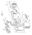
- As shown in Fig. 1, an electric car is driven by using only a driving force of an
electric motor 101. When a secondary battery, an engine generator, or a fuel battery is used as a power source for theelectric motor 101, the electric car is referred to as an electric car A in the narrow sense, a series hybrid car B, or a fuel battery car C, respectively. In Fig. 1, thereference numerals - As mentioned above, since the electric car is driven by using only a driving force of a rotary electric motor, it is defined as a car which uses a secondary battery, a fuel battery, a generator using an internal-combustion engine, a solar battery, and the like, or a combination of at least two of them as a power source for the electric motor. Although the electric car uses only a secondary battery in the following description, those skilled in the art will appreciate that the present invention is also applicable to a car which uses a fuel battery, a generator using an internal-combustion engine, or a solar battery as a power source.
- There is an urgent need to develop a totally electric car as one of decisive factors in preventing air pollution due to motorization. With the understanding that conservation of the natural environment is a big issue in the 21st century, the inventor of the present invention started the development in 1980s and is yielding results.
- Meanwhile, the inventor of the present invention has already proposed an electric car having a structure, as one of ideal structures, including an in-wheel drive system, a battery built-in frame (BBF) having a battery built under the floor thereof, and tandem wheel suspensions, each having two separate front and rear wheels mounted thereon in place of one conventional wheel.
- The reason for using the tandem wheel suspensions is that use of two wheels in place of a conventional single wheel improves the road holding, thereby providing a large acceleration force. Also, the car can keep running even when some of the wheels are damaged, and an input conveyed from the road surface to a car body through each wheel can be reduced, thereby resulting in higher ride quality.
- When tandem wheel suspensions are employed, since a large number of wheels are needed, it is necessary to convey a steering force of a steering mechanism to the large number of wheels. When a coupling mechanism is provided to each of a second axle, a third axle, a fourth axle, ---, in addition to a first axle, or when it is possible to steer a plurality of axles, a smooth turning motion can be achieved.
- In view of the above-mentioned circumstances, an object of the present invention is to provide a steering mechanism of an electric car, including tandem wheel suspensions and steering means for each pair of right and left wheels so as to achieve a smooth turning motion.
- In order to achieve the above object,
- [1] the present invention provides a steering mechanism of an electric car, which includes tandem wheel suspensions; and steering means for each pair of right and left wheels, wherein the steering means is formed by steering means operated by a steering wheel and steering means operated by a motor.
- [2] The steering mechanism of an electric car set forth in the foregoing [1] further includes a steering wheel angle sensor for detecting a steering angle of the steering wheel; and a general controller for receiving at least an output of the steering wheel angle sensor and for controlling the steering means.
- [3] The steering mechanism of an electric car set forth in the foregoing [2] further includes a motor controller for controlling a driving current of the motor of each steering means in accordance with a corresponding control output of the general controller.
- [4] In the steering mechanism of an electric car set forth in the foregoing [2], the general controller receives a variable combination of detected values of rotating-position sensors of respective wheels, steer angle sensors of respective pairs of wheels, a yaw-rate sensor, a lateral acceleration sensor, and a longitudinal acceleration sensor in order to control the steering means, in accordance with a control object.
-
- Fig. 1 illustrates the basic structure of an electric car.
- Fig. 2 is a schematic diagram of a steering system which is applicable to a tandem wheel suspension and which is controlled by a general controller and a motor controller according to a first embodiment of the present invention.
- Fig. 3 is a block diagram of the steering system which is applicable to the tandem wheel suspension and which is controlled by the general controller and the motor controller according to the first embodiment of the present invention.
- Fig. 4 illustrates a steer angle control system according to a second embodiment of the present invention, characterized by a structure for transmitting steering data.
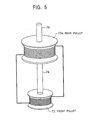
- Fig. 5 illustrates a steer angle control system according to a third embodiment of the present invention, characterized by a physical structure for transmitting steering data.
- Fig. 6 illustrates a steer angle control system according to a fourth embodiment of the present invention, characterized by another physical structure for transmitting steering data.
- Fig. 7 illustrates a steer angle control system according to a fifth embodiment of the present invention, characterized by a consistent steering-angle control.
- Fig. 8 illustrates a steer angle control system according to a sixth embodiment of the present invention, characterized by another consistent steer angle control.
- Fig. 9 illustrates a steer angle control system according to a seventh embodiment of the present invention, characterized by a simple steer angle control.
- Preferred embodiments of the present invention will be described with reference to the accompanying drawings.
- Fig. 2 is a schematic diagram of a steering system which is applicable to a tandem wheel suspension and which is controlled by a general controller and a motor controller according to a first embodiment of the present invention. Fig. 3 is a block diagram of the steering system which is applicable to the tandem wheel suspension and which is controlled by the general controller and the motor controller according to the first embodiment of the present invention.
- The present invention is intended for a car having a structure in which at least one set of a tandem wheel suspension is provided at each of the right and left sides of the car, each pair of wheels is always equipped with steering means such as a steering wheel, and six or eight wheels are provided. An embodiment of the present invention will be described on the basis of a car having a structure in which all right and left wheels are equipped with tandem wheel suspensions, and having one set of a steering wheel and the remaining three sets of steering means are provided.
- Each wheel has a motor built in its wheel, and each pair of front and rear wheels are suspended by the corresponding tandem wheel suspension. Each pair of right-front and left-front front-wheels RFF and LFF, right-front and left-front rear-wheels RFR and LFR, right-rear and left-rear front-wheels RRF and LRF, and right-rear and left-rear rear-wheels RRR and LRR is controlled as a pair of wheels in steer angle controlling.
- The wheels have rotating-
position sensors 10 to 17 attached on the corresponding axles thereof, and outputs of these rotating-position sensors are input into ageneral controller 50. - Front front-wheel steering means is constructed such that the front front-wheels RFF and LFF are manually steered when a
steering wheel 20 is operated so as to activate apower steering 21 and so forth. - Front rear-wheel steering means has an
electric motor 33 and is constructed such that theelectric motor 33 is coupled with right and left traveling axles via a speed-reduction worm gear 36 and rotation-travel converting means 30 which are rotatably disposed on the motor axle, and both ends of the traveling axles such as tie-rods are coupled with the front rear-wheels RFR and LFR via corresponding levers, knuckle arms, and so forth, and the front rear-wheel steering means is driven by the motor so as to directly achieve the automatic steering of the front rear-wheels. - Rear front-wheel steering means has an
electric motor 34 and is constructed such that theelectric motor 34 is coupled with right and left traveling axles via a speed-reduction worm gear 37 and rotation-travel converting means 31 which are rotatably disposed on the motor axle, and both ends of the traveling axles are coupled with the rear front-wheels RRF and LRF via corresponding levers, knuckle arms, and so forth, and the rear front-wheel steering means is driven by the motor so as to directly achieve the automatic steering of the rear front-wheels. - Rear rear-wheel steering means has an
electric motor 35 and is constructed such that theelectric motor 35 is coupled with right and left traveling axles via a speed-reduction worm gear 38 and rotation-travel converting means 32 which are rotatably disposed on the motor axle, and both ends of the traveling axles are coupled with the rear rear-wheels RRR and LRR via corresponding levers, knuckle arms, and so forth, and the rear rear-wheel steering means is driven by the motor so as to directly achieve the automatic steering of the rear rear-wheels. - When the power source of these motors is turned off when the car malfunctions, the irreversibility of the
worm gears - A control system includes the rotating-
position sensors 10 to 17 for detecting wheel speeds N of corresponding eight wheels, a steeringwheel angle sensor 22 for detecting a steering wheel angle θ of the steering wheel, a front rear-wheelsteer angle sensor 6 for detecting a front rear-wheel steer angle EFR, a rear front-wheelsteer angle sensor 7 for detecting a rear front-wheel steer angle ERF, a rear rear-wheelsteer angle sensor 8 for detecting a rear rear-wheel steer angle ERR, alongitudinal acceleration sensor 3 for detecting a longitudinal acceleration Gx of the car, alateral acceleration sensor 4 for detecting a lateral acceleration Gy of the car, and ayaw rate sensor 5 for detecting a yaw rate γ, that is, a turning angular speed, in accordance with the turning state of the car. Sensor signals from these sensors are input into thegeneral controller 50 so as to be electrically processed in a comprehensive manner. - Also, the control system includes an
independent motor controller 60 for controlling a large motor current of each of theelectric motors general controller 50 outputs a drive control signal of each motor, a brake signal, and a differential limiting signal so as to output steering control signals to themotor controller 60. - The
general controller 50 will be now described with reference to Fig. 3. - The
general controller 50 has a car-behavior target-value setting unit 51 into which the wheel speeds N, the steering wheel angle θ, the front rear-wheel steer angle EFR, the rear front-wheel steer angle ERF, the rear rear-wheel steer angle ERR, and the longitudinal acceleration Gx are input. The car-behavior target-value settingunit 51 computes a vehicle speed; determines the running state of the accelerated or decelerated car, the steering states of the front rear-wheels RFR and LFR, the rear front-wheels RRF and LRF, and the rear rear-wheels RRR and LRR, and so forth; and, on the basis of these parameters, numerically sets target values a for achieving a good car behavior, for example, high stability at high speed or when decelerating and a good turning ability at low speed. Also, thegeneral controller 50 has a car-behavior actual-value computing unit 52, into which the lateral acceleration Gy and the yaw rate γ are input, for numerically computing actual values b representing the changing state of the car when the behavior of the car actually changes due to a disturbance generated when the car is turning or caused by a crosswind. - The foregoing target values a and actual values b about the car behavior, the wheel speeds N, the longitudinal acceleration Gx are input into a total-driving-torque limiting-
amount setting unit 53. The total-driving-torque limiting-amount setting unit 53 numerically determines the stable or unstable degree of the car behavior by comparing the target values a and the corresponding actual values b at every step of the vehicle speed when accelerating. In the unstable state where one of the actual values b falls outside the corresponding target value a, the total-driving-torque limiting-amount setting unit 53 computes a total-driving-torque limiting amount c in accordance with a difference in these mutually corresponding values and outputs a motor control signal to in-wheel-motor control means 18 in accordance with the limiting amount c. - The wheel speeds N, the longitudinal acceleration Gx, and the total-driving-torque limiting amount c are input into a braking-
force setting unit 56. The braking-force setting unit 56 checks the total-driving-torque limiting amount c by referring to the car speed and the acceleration state. When the limiting amount c is large, the braking-force setting unit 56 sets a brake force f, and sends a brake signal of the brake force f to an automatic braking means 19. - Furthermore, since the steering of the front rear-wheels, the rear front-wheels, and the rear rear-wheels significantly affects on the stability and the turning ability of the car behavior, the target values a and the actual values b are input into an all-wheels steer
angle setting unit 57. The all-wheels steerangle setting unit 57 computes a target front rear-wheel steer angle EFR, rear front-wheel steer angle ERF, and rear rear-wheel steer angle ERR in the same fashion as in the above mentioned in accordance with differences in the target values a and the corresponding actual values b, and outputs steering control signals of the target front rear-wheel steer angle EFR, rear front-wheel steer angle ERF, and rear rear-wheel steer angle ERR to themotor controller 60. - The
motor controller 60 has a motor-current setting unit 61, into which steering control signals are input, for deciding target motor currents It in accordance with the front rear-wheel steer angle EFR, rear front-wheel steer angle ERF, and rear rear-wheel steering-angle ERR. Current signals of these motor currents It are input into adriving unit 62 so as to feed predetermined large motor currents I to theelectric motors - When the car is operated by a driver so as to run straight or turn with the eight drive wheels while being accelerated or decelerated, signals of the various sensors are always input into the
general controller 50 for setting the target values a and computing the actual values b of the car behavior. Thegeneral controller 50 sets in-wheel-motor driving currents e of the right and left motors and target wheel steer angles E of the right and left wheels on the basis of the target values a and the actual values b of the car behavior. While the car is running straight or turning, when the car behavior becomes unstable when one of the actual values b falls outside the corresponding target value a, the driving currents e in accordance with differences in these mutually corresponding values are output to right and left in-wheel motors, thereby limiting unnecessary movements of the right and left wheels and thus performing a drive control so as to achieve the car stability. - Meanwhile, while the car is running straight, when the car behavior becomes unstable when one of the actual values b falls outside the corresponding target value a due to a crosswind or the like, the target front rear-wheel steer angles E are set in accordance with differences in these mutually corresponding values and steering control signals of the above target front rear-wheel steer angles E are output to the
motor controller 60. Then, in themotor controller 60, the target motor currents It are set in accordance with the target front rear-wheel steer angles E and a large motor current is fed to anelectric motor 33 of the rotation-travel converting means 30 by the drivingunit 62. - With this arrangement, due to torques generated by the in-wheel-motor driving currents e of the right and left in-wheel motors, the corresponding front rear-wheels, rear front-wheels, and rear rear-wheels are directly driven and steered in a predetermined relationship, thereby performing a steering control so as to achieve the car stability. Also, when the car is turned at very low speed, the rear front-wheels and the rear rear-wheels are driven to steer in anti-phase with each other side by the corresponding in-wheel motors so as to achieve a small turning motion.
- Although a steering control of each pair of wheels is performed by an electric motor equipped with a worm gear to which the
general controller 50 sends a command on the basis of an output of the steeringwheel angle sensor 22 in the foregoing embodiment, a variety of modifications are possible. For example, instead of the steering means formed by the motor equipped with a worm gear and the rotation-travel converting means, steering means formed by steering wheels, that is, steering means formed by a plurality of steering wheels is provided so as to be operative mutually with steering means formed by the remaining motors. - A servomechanism for performing the steering of the car is of an electric type. The servomechanism is fixed to only one of the steering shafts and its force is distributed to each of the steering shafts or fixed to each of the steering shafts. A flexible wire is sometimes used to convey a force from the steering wheel to each of the steering shafts, and another flexible wire is sometimes used to convey a force from one steering shaft to another shaft. The rearmost steering shaft is steered in anti-phase phase at low speed and in phase at high speed with the foremost steering shaft.
- In order to transmit a command for performing the steering from the steering wheel to each steering system, mechanical transmitting means, electrical transmitting means, or sound waves are used. The servomechanism for performing the steering is sometimes directly fixed to a kingpin without having a steering rod interposed therebetween. The shafts of the kingpins are sometimes connected to each other by a rigid member, wire, or the like for the safety of the car.
- Referring now to Fig. 4, a second embodiment of the present invention will be described.
- As shown in Fig. 4, a steering angle of a
steering wheel 71 is transmitted to a steering wheel angle sensor (a rotary encoder) 72, apulley 73, a torque sensor (a torsional torque sensor) 74, and agear box 75. The rotation angle transmitted to thegear box 75 is transmitted to tie-rods or the like via the corresponding steering shaft having amotor 77 disposed thereon so as to steer the corresponding wheels. At the same time, a servo force of themotor 77 is fed back to thetorque sensor 74 via thegear box 75 so as to perform a feedback control. In conjunction with the feedback control, the following steer angle controls (1) and (2) are performed. - (1) Upon receiving detected values of a
steer angle sensor 78 and the steering wheel angle sensor (such as a rotary encoder or a potentiometer) 72, fixed to asteering shaft 79, for detecting a steering angle of thesteering wheel 71, controllers for controlling the steering shafts of the other wheels, in particular,controllers motors - (2) A
gear box 75a, to which a servo-motor 77a, apulley 73a, and atorque sensor 74a are connected, is disposed on the steering shaft of the right-front and left-front rear-wheels. Since thepulley 73a is coupled with thepulley 73 by a wire, the steering angle of thesteering wheel 71 can be reproduced. A steering force is detected by thetorque sensor 74a. On the basis of the detected value, thecontroller 76a issues a command to themotor 77a so as to produce a servo effect, and also perform a feedback control by feeding back the detected value to thetorque sensor 74a via thegear box 75a. - Since the detected value of the
steering wheel 71 is transmitted by the above mentioned electrical means and mechanical means which are different from each other, even when one of the transmission systems malfunctions, the steering of the car can be still maintained by the other transmission system. - Referring now to Figs. 4 and 5, a third embodiment of the present invention will be described.
- As shown in Fig. 5, the diameter of the
rear pulley 73a is made greater than that of thefront pulley 73, both used in the second embodiment. With this arrangement, since thepulley 73 with a small diameter can be allotted to thesteering wheel 71 having a long steering stroke, a steering wheel angle can be transmitted in concert with a motion of thesteering wheel 71. - Referring now to Figs. 4 and 6, a fourth embodiment of the present invention will be described.
- In this embodiment, a steering wheel angle is detected by using a combination of a gear box and a rod serving as physical transmitting means, instead of using the pulley in the second embodiment. A steering angle of the
steering wheel 71 is transmitted to thegear box 75a andgear boxes 75b and 75c disposed on the other corresponding steering shafts from thegear box 75 via the rod. With this structure, the steering wheel angle can be transmitted by the physical transmitting means, in particular, formed by a rigid rod instead of a bendable member such as a wire, thereby making the transmitted steering wheel angle more accurate. At the same time, thecontrollers controller 76c perform a feedback control by feeding back detected values of thetorque sensor 74a andtorque sensors 74b and 74c to the corresponding controllers, respectively. - Referring now to Fig. 7, a fifth embodiment of the present invention will be described.
- As shown in Fig. 7, this embodiment is characterized in that all steering systems are controlled on the basis of a detected value of a single steer angle sensor. The steering
shaft 79 is coupled with a steering arm 81 (1) directly or (2) via thegear box 75 of a steering gear, and the steering-angle sensor 78 detects a displacement of thesteering arm 81. - A steering angle of the steering
shaft 79 is detected by thesteer angle sensor 78 and is input into all the steering systems as a sole detected value. Acontroller 76 and thecontrollers motors steer angle sensor 78, the detected value varying in accordance with the steering angle, so as to produce a servo effect. As a result, one detected result is used as common data for controlling each of the steering systems, thereby achieving a consistent control over all the steering systems. - The
controller 76 receives a steering angle of the steeringshaft 79 as a detected value of thesteer angle sensor 78 and controls themotor 77 on the basis of the detected value so as to drive thesteering arm 81. Thecontroller 76 feeds back the turning angle, that is, the controlled result, of thesteering arm 81 to itself via thegear box 75 as a detected result of thesteer angle sensor 78 so as to perform a feedback control. The detected result of thesteer angle sensor 78 is used as a sole input value to all the other steering systems and thecontrollers motors steering arm 81, and steeringarms arms steer angle sensor 78a and thesteer angle sensors - Referring now to Fig. 8, a sixth embodiment of the present invention will be described.
- This embodiment is characterized in that a single detected value of a steering angle is used as a sole input value and a sole controller controls all the steering systems.
- A steering angle of the steering
shaft 79 is detected by the steeringwheel angle sensor 72. Thecontroller 76 controls themotors motor 77 is detected by thetorque sensor 74 via the corresponding steering shaft and thegear box 75 as detected data of a steering force; is fed back to thecontroller 76; and is controlled so as to produce a servo effect in order to reduce the steering force. In this control system, all the steering systems are controlled by a sole controller on the basis of a sole detected data of a steering angle, thereby achieving the consistent steering of the steering systems as a whole. - Referring now to Figs. 4 and 9, a seventh embodiment of the present embodiment will be described.
- As shown in Fig. 9, a steering angle of the
steering wheel 71 or a joy stick is detected by the steeringwheel angle sensor 72 and is input into thecontroller 76. Thecontroller 76 controls steer angles of pairs of steeringmotors motors steer angle sensors controller 76 for controlling the steering of all wheels. Thecontroller 76 forms a feedback control system on the basis of the detected results of the steeringwheel angle sensor 72 and thesteer angle sensors - Each wheel is equipped with the corresponding one of the
steering motors motors attachment 86; the first supportingattachment 86 is supported by a universal joint 90 having a second supportingattachment 89 interposed therebetween; and the second supportingattachment 89 is suspended bysuspensions steering motors attachment 86, and the motor has amale screw groove 88 formed on the end part, opposite to the motor, of its shaft passing through the first supportingattachment 86. Acylindrical member 91 having afemale screw portion 87 formed therein which screws together with themale screw groove 88 is swingably and rotatably supported by the second supportingattachment 89. When thesteering motors male screw groove 88 of the motor axle of each motor moves in or out from thefemale screw portion 87 of thecylindrical member 91 rotatably supported by the second supportingattachment 89 in a state in which the male screw groove 88 screws together with thefemale screw portion 87, thereby performing a steering control of each wheel. Thesteer angle sensors cylindrical members 91 and detect steering angles of thesteering motors steering motors cylindrical members 91, thereby achieving a compact steering mechanism having a simple structure. Also, a direct steering control can be performed by a control command from a controller, thereby achieving an accurate control with a small margin of control error. - Although the steering mechanism for eight wheels has been described in the above-mentioned embodiments, the one for six wheels basically has the same structure, and the same handling and operating configuration as those of the steering mechanism for eight wheels. Also, although an in-wheel motor is used as a driving source in this embodiment, a gasoline engine or a hybrid engine may be used.
- The present invention is not limited to the above-described embodiments, and a variety of modifications based on the spirit of the present invention shall not be excluded from the scope of the present invention.
- As described above in detail, the present invention offers the following advantages.
- (A) In an electric car equipped with tandem wheel suspensions, a steering mechanism is formed so as to perform a smooth turning motion. That is, in a car comprehensively performing a drive control and a steering control, a general controller and a motor controller are independently disposed from each other, the former for comprehensively processing signals of variety of sensors and outputting signals for performing a drive control and a steering control on the basis of the car behavior, and the latter for controlling a motor current of an electric motor of an electric wheel steering means, thereby making the control system of the general controller small and compact.
By independently providing the motor controller as described above, a large motor current of the electric wheel steering means can be optimally controlled. Also, the motor controller can easily respond to the presence or absence of the electric wheel steering means, a change in load capacities between small and large cars, and the like. In addition, a smooth turning and steering motion of the car equipped with the tandem wheel suspensions can be achieved. - (B) In an electric car equipped with tandem wheel suspensions, by providing a coupling mechanism for coupling a first axle with each of other axles, a smooth turning motion can be achieved.
- (C) In an electric car equipped with tandem wheel suspensions, by providing steering mechanisms to at least two axles, a smooth turning motion can be achieved.
- (D) By independently providing a motor controller, a large motor current of electric wheel steering means can be optimally controlled. Also, the motor controller can easily respond to the presence or absence of the electric wheel steering means, a change in load capacities between small and large cars, and the like. In addition, a smooth turning and steering motion of the car equipped with the tandem wheel suspensions can be achieved.
- (E) With the advantages of above (A), (B), (C), and (D), the operability of the car improves and a smooth turning motion can be achieved, thereby resulting in higher ride quality.
- Since a steering mechanism of an electric car according to the present invention has tandem wheel suspensions and steering means for each pair of right and left wheels, a smooth turning motion can be achieved, whereby the steering mechanism is especially suitable for use in an electric car which does not emit an exhaust gas and hence prevents the global warming.
Claims (4)
- A steering mechanism of an electric car, comprising: tandem wheel suspensions; and steering means for each pair of right and left wheels,
wherein the steering means comprises steering means operated by a steering wheel and steering means operated by a motor. - The steering mechanism of an electric car according to Claim 1, further comprising: a steer angle sensor for detecting a steering angle of the steering wheel; and a general controller for receiving at least an output of the steer angle sensor and for controlling the steering means.
- The steering mechanism of an electric car according to Claim 2, further comprising a motor controller for controlling a driving current of the motor of each steering means in accordance with a corresponding control output of the general controller.
- The steering mechanism of an electric car according to Claim 2, wherein the general controller receives a variable combination of detected values of rotating-position sensors of respective wheels, steer angle sensors of respective pairs of wheels, a yaw-rate sensor, a lateral acceleration sensor, and a longitudinal acceleration sensor in order to control the steering means, in accordance with a control object.
Applications Claiming Priority (3)
| Application Number | Priority Date | Filing Date | Title |
|---|---|---|---|
| JP2000377715 | 2000-12-12 | ||
| JP2000377715 | 2000-12-12 | ||
| PCT/JP2001/009419 WO2002047936A1 (en) | 2000-12-12 | 2001-10-26 | Steering mechanism of electric car |
Publications (3)
| Publication Number | Publication Date |
|---|---|
| EP1342609A1 true EP1342609A1 (en) | 2003-09-10 |
| EP1342609A4 EP1342609A4 (en) | 2005-12-14 |
| EP1342609B1 EP1342609B1 (en) | 2008-06-18 |
Family
ID=18846391
Family Applications (1)
| Application Number | Title | Priority Date | Filing Date |
|---|---|---|---|
| EP01980915A Expired - Lifetime EP1342609B1 (en) | 2000-12-12 | 2001-10-26 | Steering mechanism of electric car |
Country Status (5)
| Country | Link |
|---|---|
| US (1) | US6863149B2 (en) |
| EP (1) | EP1342609B1 (en) |
| JP (1) | JP4030871B2 (en) |
| DE (1) | DE60134493D1 (en) |
| WO (1) | WO2002047936A1 (en) |
Families Citing this family (7)
| Publication number | Priority date | Publication date | Assignee | Title |
|---|---|---|---|---|
| JP3476770B2 (en) * | 2000-12-18 | 2003-12-10 | 科学技術振興事業団 | Electric vehicle control device |
| AU2002332563A1 (en) * | 2001-08-23 | 2003-03-10 | General Motors Corporation | Vehicle chassis having systems responsive to non-mechanical control signals |
| US7213855B2 (en) * | 2004-03-08 | 2007-05-08 | Larson Dickie L | Hearse assembly |
| JP2005289324A (en) * | 2004-04-05 | 2005-10-20 | Bridgestone Corp | Vehicle having auxiliary driving motor for of rear wheel |
| US7521814B2 (en) * | 2004-09-27 | 2009-04-21 | Oshkosh Truck Corporation | System and method for providing low voltage 3-phase power in a vehicle |
| IL174061A0 (en) * | 2006-03-02 | 2006-08-01 | Amihud Rabin | Safety control system for electric vehicle |
| US11597457B2 (en) * | 2018-10-12 | 2023-03-07 | New Heights, Llc | Self-propelled tandem axle trailer |
Family Cites Families (107)
| Publication number | Priority date | Publication date | Assignee | Title |
|---|---|---|---|---|
| US3240621A (en) * | 1960-11-14 | 1966-03-15 | Dictaphone Corp | High viscosity dispersions of magnetic pigments |
| US3790858A (en) * | 1973-01-29 | 1974-02-05 | Itt | Electrical connector with component grounding plate |
| US4139783A (en) * | 1975-09-02 | 1979-02-13 | General Electric Company | Single phase signal processing system utilizing charge transfer devices |
| SE392010B (en) * | 1976-02-27 | 1977-03-07 | Ericsson Telefon Ab L M | NET FOR COMPENSATION OF LOSS DAMPING TEMPERATURE DEVIATION IN A PASSIVE FILTER |
| JPS5445707A (en) * | 1977-09-17 | 1979-04-11 | Canon Inc | Dc electric machine |
| US4191986A (en) * | 1978-05-12 | 1980-03-04 | The United States Of America As Represented By The Secretary Of The Navy | Power line transient suppressors |
| US4568104A (en) * | 1978-07-21 | 1986-02-04 | Leblanc James C | Armored vehicle steering system |
| JPS6311704Y2 (en) * | 1979-06-11 | 1988-04-05 | ||
| DE3147787A1 (en) * | 1981-12-03 | 1983-09-15 | Helmut Dipl.-Ing. 8106 Oberau Frey | Combined locking and differential steering |
| US4494092A (en) * | 1982-07-12 | 1985-01-15 | The Deutsch Company Electronic Components Division | Filter pin electrical connector |
| US4563659A (en) * | 1982-07-28 | 1986-01-07 | Murata Manufacturing Co., Ltd. | Noise filter |
| US4814941A (en) * | 1984-06-08 | 1989-03-21 | Steelcase Inc. | Power receptacle and nested line conditioner arrangement |
| JPS611917U (en) * | 1984-06-08 | 1986-01-08 | 株式会社村田製作所 | noise filter |
| US5089688A (en) * | 1984-07-10 | 1992-02-18 | Raychem Corporation | Composite circuit protection devices |
| GB8418779D0 (en) * | 1984-07-24 | 1984-08-30 | Bowthorpe Emp Ltd | Electrical surge protection |
| JPS628512A (en) * | 1985-07-04 | 1987-01-16 | 株式会社村田製作所 | Ic composite part |
| US4908590A (en) * | 1986-01-14 | 1990-03-13 | Murata Manufacturing Co., Ltd. | Chip-like LC filter |
| US4801904A (en) * | 1986-01-14 | 1989-01-31 | Murata Manufacturing Co., Ltd. | Chip-like LC filter |
| JPS62205615A (en) * | 1986-03-05 | 1987-09-10 | 株式会社村田製作所 | Metallization of ceramics |
| US4799070A (en) * | 1986-03-26 | 1989-01-17 | Olympus Optical Co., Ltd. | Ion flow electrostatic recording process and apparatus |
| KR880003356A (en) * | 1986-08-13 | 1988-05-16 | 무라다 아끼라 | High pressure capacitor |
| US4814295A (en) * | 1986-11-26 | 1989-03-21 | Northern Telecom Limited | Mounting of semiconductor chips on a plastic substrate |
| US4908586A (en) * | 1987-09-30 | 1990-03-13 | Amp Incorporated | Compact encapsulated filter assembly for printed circuit boards and method of manufacture thereof |
| US4999595A (en) * | 1988-01-22 | 1991-03-12 | Murata Manufacturing Co., Ltd. | LC filter structure |
| JP2598940B2 (en) * | 1988-01-27 | 1997-04-09 | 株式会社村田製作所 | LC composite parts |
| JP2790462B2 (en) * | 1988-05-25 | 1998-08-27 | 新日本製鐵株式会社 | Electric vehicle control device |
| US5079223A (en) * | 1988-12-19 | 1992-01-07 | Arch Development Corporation | Method of bonding metals to ceramics |
| US5079669A (en) * | 1989-04-10 | 1992-01-07 | Williams Bruce T | Electrophotographic charging system and method |
| US5079069A (en) * | 1989-08-23 | 1992-01-07 | Zycon Corporation | Capacitor laminate for use in capacitive printed circuit boards and methods of manufacture |
| US5179362A (en) * | 1989-12-15 | 1993-01-12 | Kabushiki Kaisha Toshiba | Power line filter |
| US5091140A (en) * | 1990-01-22 | 1992-02-25 | The Babcock & Wilcox Company | Method of replacing a heater nozzle in a nuclear reactor pressurizer |
| US6183685B1 (en) * | 1990-06-26 | 2001-02-06 | Littlefuse Inc. | Varistor manufacturing method |
| US5382938A (en) * | 1990-10-30 | 1995-01-17 | Asea Brown Boveri Ab | PTC element |
| JP2606044B2 (en) * | 1991-04-24 | 1997-04-30 | 松下電器産業株式会社 | Dielectric filter |
| US5181859A (en) * | 1991-04-29 | 1993-01-26 | Trw Inc. | Electrical connector circuit wafer |
| US5579228A (en) * | 1991-05-21 | 1996-11-26 | University Of Utah Research Foundation | Steering control system for trailers |
| US5401952A (en) * | 1991-10-25 | 1995-03-28 | Canon Kabushiki Kaisha | Signal processor having avalanche photodiodes |
| US5186647A (en) * | 1992-02-24 | 1993-02-16 | At&T Bell Laboratories | High frequency electrical connector |
| US5378407A (en) * | 1992-06-05 | 1995-01-03 | Raychem Corporation | Conductive polymer composition |
| US5266912A (en) * | 1992-08-19 | 1993-11-30 | Micron Technology, Inc. | Inherently impedance matched multiple integrated circuit module |
| EP0589560B1 (en) * | 1992-09-23 | 1997-10-22 | The Whitaker Corporation | Electrical overstress protection apparatus |
| KR960013043B1 (en) * | 1992-10-23 | 1996-09-25 | 삼성전기 주식회사 | 3 terminal noise filter and manufacturing method |
| JP3265669B2 (en) * | 1993-01-19 | 2002-03-11 | 株式会社デンソー | Printed board |
| JPH06219348A (en) | 1993-01-22 | 1994-08-09 | Mazda Motor Corp | Towing vehicle and towing vehicle system |
| US5382928A (en) * | 1993-01-22 | 1995-01-17 | The Whitaker Corporation | RF filter having composite dielectric layer and method of manufacture |
| JPH06252285A (en) * | 1993-02-24 | 1994-09-09 | Fuji Xerox Co Ltd | Circuit board |
| US5475606A (en) * | 1993-03-05 | 1995-12-12 | International Business Machines Corporation | Faraday cage for a printed circuit card |
| JPH06335115A (en) * | 1993-05-25 | 1994-12-02 | Nissan Motor Co Ltd | Vehicle motion controller |
| JPH0721903A (en) * | 1993-07-01 | 1995-01-24 | Nec Corp | Electron gun structure for cathode-ray tube using field emission type cathode |
| US5500629A (en) * | 1993-09-10 | 1996-03-19 | Meyer Dennis R | Noise suppressor |
| US5495180A (en) * | 1994-02-04 | 1996-02-27 | The United States Of America As Represented By The Secretary Of The Air Force | DC biasing and AC loading of high gain frequency transistors |
| JPH07235775A (en) * | 1994-02-21 | 1995-09-05 | Mitsubishi Electric Corp | Multilayer printed wiring substrate |
| JPH07257416A (en) * | 1994-03-18 | 1995-10-09 | Honda Motor Co Ltd | Control method of front and rear wheel steering vehicle |
| US5481238A (en) * | 1994-04-19 | 1996-01-02 | Argus Technologies Ltd. | Compound inductors for use in switching regulators |
| US5491299A (en) * | 1994-06-03 | 1996-02-13 | Siemens Medical Systems, Inc. | Flexible multi-parameter cable |
| FR2724527B1 (en) * | 1994-09-13 | 1996-11-22 | Alsthom Cge Alcatel | ARRANGEMENTS FOR REDUCING THE ELECTROMAGNETIC FIELD EMITTED BY POWER ELECTRONIC EQUIPMENT |
| US5719450A (en) * | 1994-10-17 | 1998-02-17 | Vora; Pramod | Touch responsive electric power controller |
| US5614881A (en) * | 1995-08-11 | 1997-03-25 | General Electric Company | Current limiting device |
| JP3869045B2 (en) * | 1995-11-09 | 2007-01-17 | 株式会社日立製作所 | Semiconductor memory device |
| JP3177897B2 (en) * | 1996-04-23 | 2001-06-18 | ザール テクノロジー リミテッド | Droplet deposit device |
| US5875099A (en) * | 1996-05-09 | 1999-02-23 | Murata Manufacturing Co., Ltd. | Electronic component |
| US5908350A (en) * | 1996-06-04 | 1999-06-01 | Ralph Dalton | Device for removing stains from swimming pool walls and concrete |
| US5708553A (en) * | 1996-07-18 | 1998-01-13 | Hung; Je | Automatic switching-off structure for protecting electronic device from burning |
| GB2315471B (en) * | 1996-07-24 | 1998-10-07 | Mitchell George W | Steerable trailers |
| US6131691A (en) * | 1996-09-13 | 2000-10-17 | Morch & Sonner A/S | System for guided steering of at least one set of wheels of a semi-trailer or a trailer |
| WO1998020557A1 (en) * | 1996-11-08 | 1998-05-14 | W.L. Gore & Associates, Inc. | Method for reducing via inductance in an electronic assembly and device |
| JPH10149948A (en) * | 1996-11-19 | 1998-06-02 | Tdk Corp | High-voltage coaxial capacitor |
| JP3092542B2 (en) * | 1997-03-10 | 2000-09-25 | 株式会社村田製作所 | LC composite parts |
| US6995983B1 (en) * | 1997-04-08 | 2006-02-07 | X2Y Attenuators, Llc | Component carrier |
| DE19714485A1 (en) * | 1997-04-08 | 1998-10-15 | Kidde Ind Inc | Steering for a multi-axle vehicle |
| US6687108B1 (en) * | 1997-04-08 | 2004-02-03 | X2Y Attenuators, Llc | Passive electrostatic shielding structure for electrical circuitry and energy conditioning with outer partial shielded energy pathways |
| US7110235B2 (en) * | 1997-04-08 | 2006-09-19 | Xzy Altenuators, Llc | Arrangement for energy conditioning |
| US6606011B2 (en) * | 1998-04-07 | 2003-08-12 | X2Y Attenuators, Llc | Energy conditioning circuit assembly |
| US6603646B2 (en) * | 1997-04-08 | 2003-08-05 | X2Y Attenuators, Llc | Multi-functional energy conditioner |
| US6509807B1 (en) * | 1997-04-08 | 2003-01-21 | X2Y Attenuators, Llc | Energy conditioning circuit assembly |
| US7106570B2 (en) * | 1997-04-08 | 2006-09-12 | Xzy Altenuators, Llc | Pathway arrangement |
| JPH10278596A (en) * | 1997-04-08 | 1998-10-20 | Hiroshi Shimizu | Electric vehicle |
| US6018448A (en) * | 1997-04-08 | 2000-01-25 | X2Y Attenuators, L.L.C. | Paired multi-layered dielectric independent passive component architecture resulting in differential and common mode filtering with surge protection in one integrated package |
| US5870272A (en) * | 1997-05-06 | 1999-02-09 | Medtronic Inc. | Capacitive filter feedthrough for implantable medical device |
| US6175287B1 (en) * | 1997-05-28 | 2001-01-16 | Raytheon Company | Direct backside interconnect for multiple chip assemblies |
| US5880925A (en) * | 1997-06-27 | 1999-03-09 | Avx Corporation | Surface mount multilayer capacitor |
| JP3982876B2 (en) * | 1997-06-30 | 2007-09-26 | 沖電気工業株式会社 | Surface acoustic wave device |
| US5889445A (en) * | 1997-07-22 | 1999-03-30 | Avx Corporation | Multilayer ceramic RC device |
| NO306813B1 (en) * | 1997-09-08 | 1999-12-27 | Bauer Nilsen Magnus | Steering mechanism for swivel wheels on motor vehicles |
| DE19741746C1 (en) * | 1997-09-22 | 1999-02-04 | Siemens Ag | Signal line coupling module e.g. for signals lead-in into screened HF-screening cubicle or cabinet for magnetic resonance diagnostic device |
| US6342681B1 (en) * | 1997-10-15 | 2002-01-29 | Avx Corporation | Surface mount coupler device |
| JP2991175B2 (en) * | 1997-11-10 | 1999-12-20 | 株式会社村田製作所 | Multilayer capacitors |
| US6191475B1 (en) * | 1997-11-26 | 2001-02-20 | Intel Corporation | Substrate for reducing electromagnetic interference and enclosure |
| JP3451912B2 (en) | 1997-12-18 | 2003-09-29 | トヨタ自動車株式会社 | Drive control device for electric vehicles |
| JPH11205006A (en) * | 1998-01-20 | 1999-07-30 | Matsushita Electric Ind Co Ltd | Laminated filter |
| US5877455A (en) | 1998-01-21 | 1999-03-02 | Meritor Heavy Vehicle Systems, Llc | Payload monitoring for a tractor-trailer |
| US6185091B1 (en) * | 1998-02-09 | 2001-02-06 | Matsushita Electric Industrial Co., Ltd. | Four-terminal capacitor |
| US6181231B1 (en) * | 1998-04-06 | 2001-01-30 | Silicon Graphics, Inc. | Diamond-based transformers and power convertors |
| JP3336954B2 (en) * | 1998-05-21 | 2002-10-21 | 株式会社村田製作所 | Multilayer capacitors |
| JP4236017B2 (en) * | 1998-06-12 | 2009-03-11 | 株式会社アイペックス | Noise prevention device |
| US6016095A (en) * | 1998-07-06 | 2000-01-18 | Herbert; Edward | Snubber for electric circuits |
| US6392502B2 (en) * | 1998-12-17 | 2002-05-21 | The Whitaker Corporation | Balun assembly with reliable coaxial connection |
| US6157528A (en) * | 1999-01-28 | 2000-12-05 | X2Y Attenuators, L.L.C. | Polymer fuse and filter apparatus |
| JP2001156569A (en) * | 1999-11-26 | 2001-06-08 | Murata Mfg Co Ltd | Layered lc composite component |
| US6567257B2 (en) * | 2000-04-19 | 2003-05-20 | Applied Materials, Inc. | Method and apparatus for conditioning an electrostatic chuck |
| JP3773396B2 (en) * | 2000-06-01 | 2006-05-10 | 住友電気工業株式会社 | Contact probe and manufacturing method thereof |
| JP3551899B2 (en) * | 2000-06-26 | 2004-08-11 | 株式会社村田製作所 | Resonator, filter, duplexer and communication device |
| US6425452B1 (en) * | 2000-07-26 | 2002-07-30 | Venture Products, Inc. | Control system for all-wheel drive vehicle |
| WO2002013135A2 (en) * | 2000-08-04 | 2002-02-14 | Hei, Inc. | Structures and assembly methods for radio-frequency-identification modules |
| AU2001283565A1 (en) * | 2000-08-15 | 2002-02-25 | X2Y Attenuators, L.L.C. | An electrode arrangement for circuit energy conditioning |
| US6488114B1 (en) * | 2001-02-12 | 2002-12-03 | Balzer, Inc. | Grain cart |
| JP2006528868A (en) * | 2003-07-21 | 2006-12-21 | エックストゥーワイ アテニュエイターズ,エルエルシー | Filter assembly |
-
2001
- 2001-10-26 US US10/433,778 patent/US6863149B2/en not_active Expired - Fee Related
- 2001-10-26 EP EP01980915A patent/EP1342609B1/en not_active Expired - Lifetime
- 2001-10-26 WO PCT/JP2001/009419 patent/WO2002047936A1/en active IP Right Grant
- 2001-10-26 DE DE60134493T patent/DE60134493D1/en not_active Expired - Lifetime
- 2001-10-26 JP JP2002549489A patent/JP4030871B2/en not_active Expired - Fee Related
Non-Patent Citations (2)
| Title |
|---|
| No further relevant documents disclosed * |
| See also references of WO0247936A1 * |
Also Published As
| Publication number | Publication date |
|---|---|
| JP4030871B2 (en) | 2008-01-09 |
| WO2002047936A1 (en) | 2002-06-20 |
| EP1342609A4 (en) | 2005-12-14 |
| DE60134493D1 (en) | 2008-07-31 |
| US20040050596A1 (en) | 2004-03-18 |
| US6863149B2 (en) | 2005-03-08 |
| EP1342609B1 (en) | 2008-06-18 |
| JPWO2002047936A1 (en) | 2004-04-15 |
Similar Documents
| Publication | Publication Date | Title |
|---|---|---|
| US8781684B2 (en) | Steering and control systems for a three-wheeled vehicle | |
| US5469928A (en) | Assisted steering system for non-trackbound vehicle | |
| CN107685767B (en) | Multiaxis wheel-hub motor driven vehicle rear-wheel steering-by-wire driving device and forward method | |
| US7578361B2 (en) | Differential steering assist system for utility vehicle | |
| JP4389993B2 (en) | Vehicle steering device | |
| JP5423391B2 (en) | Vehicle speed control device | |
| WO1990011905A1 (en) | Electric car | |
| GB2320003A (en) | Vehicle power steering control | |
| CN110466602A (en) | The timesharing four-wheel steering system and its control method of hub motor driven electric vehicle | |
| CN108163044A (en) | The steering redundancy of four motorized wheels electric vehicle and integrated control system and method | |
| CN101873960B (en) | Rear-wheel steering vehicle | |
| CN112026777B (en) | Vehicle composite steering system and mode switching control method thereof | |
| EP1342609B1 (en) | Steering mechanism of electric car | |
| JP2984724B2 (en) | Electric car | |
| JP2006187047A (en) | Driving force controller for four-wheel independent drive vehicle | |
| JP3571289B2 (en) | Electric vehicle steering system | |
| JPH0221341Y2 (en) | ||
| JPH11129926A (en) | Steering control wheel control structure | |
| GB2395698A (en) | Drive control of plural steering mode truck | |
| KR102620426B1 (en) | Steering device | |
| JPH07108949A (en) | Integrated control device for vehicle | |
| JPS63184576A (en) | Rear wheel steering device for automobile | |
| JPH0221340Y2 (en) | ||
| CN114734834A (en) | Electronic differential control system for double motors of rear axle of electric vehicle | |
| CN114701565A (en) | Four-wheel steering independent wheel steering driving device and control method thereof |
Legal Events
| Date | Code | Title | Description |
|---|---|---|---|
| PUAI | Public reference made under article 153(3) epc to a published international application that has entered the european phase |
Free format text: ORIGINAL CODE: 0009012 |
|
| 17P | Request for examination filed |
Effective date: 20030612 |
|
| AK | Designated contracting states |
Kind code of ref document: A1 Designated state(s): AT BE CH CY DE DK ES FI FR GB GR IE IT LI LU MC NL PT SE TR |
|
| RBV | Designated contracting states (corrected) |
Designated state(s): DE FR GB |
|
| RAP1 | Party data changed (applicant data changed or rights of an application transferred) |
Owner name: JAPAN SCIENCE AND TECHNOLOGY AGENCY |
|
| RAP1 | Party data changed (applicant data changed or rights of an application transferred) |
Owner name: JAPAN SCIENCE AND TECHNOLOGY AGENCY |
|
| A4 | Supplementary search report drawn up and despatched |
Effective date: 20051103 |
|
| 17Q | First examination report despatched |
Effective date: 20060705 |
|
| GRAP | Despatch of communication of intention to grant a patent |
Free format text: ORIGINAL CODE: EPIDOSNIGR1 |
|
| RBV | Designated contracting states (corrected) |
Designated state(s): DE FR IT |
|
| GRAS | Grant fee paid |
Free format text: ORIGINAL CODE: EPIDOSNIGR3 |
|
| GRAA | (expected) grant |
Free format text: ORIGINAL CODE: 0009210 |
|
| AK | Designated contracting states |
Kind code of ref document: B1 Designated state(s): DE FR IT |
|
| REF | Corresponds to: |
Ref document number: 60134493 Country of ref document: DE Date of ref document: 20080731 Kind code of ref document: P |
|
| PLBE | No opposition filed within time limit |
Free format text: ORIGINAL CODE: 0009261 |
|
| STAA | Information on the status of an ep patent application or granted ep patent |
Free format text: STATUS: NO OPPOSITION FILED WITHIN TIME LIMIT |
|
| 26N | No opposition filed |
Effective date: 20090319 |
|
| PGFP | Annual fee paid to national office [announced via postgrant information from national office to epo] |
Ref country code: DE Payment date: 20101020 Year of fee payment: 10 |
|
| PGFP | Annual fee paid to national office [announced via postgrant information from national office to epo] |
Ref country code: IT Payment date: 20101022 Year of fee payment: 10 |
|
| PGFP | Annual fee paid to national office [announced via postgrant information from national office to epo] |
Ref country code: FR Payment date: 20111103 Year of fee payment: 11 |
|
| REG | Reference to a national code |
Ref country code: FR Ref legal event code: ST Effective date: 20130628 |
|
| PG25 | Lapsed in a contracting state [announced via postgrant information from national office to epo] |
Ref country code: DE Free format text: LAPSE BECAUSE OF NON-PAYMENT OF DUE FEES Effective date: 20130501 |
|
| REG | Reference to a national code |
Ref country code: DE Ref legal event code: R119 Ref document number: 60134493 Country of ref document: DE Effective date: 20130501 |
|
| PG25 | Lapsed in a contracting state [announced via postgrant information from national office to epo] |
Ref country code: IT Free format text: LAPSE BECAUSE OF NON-PAYMENT OF DUE FEES Effective date: 20121026 Ref country code: FR Free format text: LAPSE BECAUSE OF NON-PAYMENT OF DUE FEES Effective date: 20121031 |