EP1298520A1 - Stabilizing system for computer hardware - Google Patents
Stabilizing system for computer hardware Download PDFInfo
- Publication number
- EP1298520A1 EP1298520A1 EP20010410125 EP01410125A EP1298520A1 EP 1298520 A1 EP1298520 A1 EP 1298520A1 EP 20010410125 EP20010410125 EP 20010410125 EP 01410125 A EP01410125 A EP 01410125A EP 1298520 A1 EP1298520 A1 EP 1298520A1
- Authority
- EP
- European Patent Office
- Prior art keywords
- stabilizer
- recess
- engagement
- locking
- chassis cover
- Prior art date
- Legal status (The legal status is an assumption and is not a legal conclusion. Google has not performed a legal analysis and makes no representation as to the accuracy of the status listed.)
- Granted
Links
Images


Classifications
-
- F—MECHANICAL ENGINEERING; LIGHTING; HEATING; WEAPONS; BLASTING
- F16—ENGINEERING ELEMENTS AND UNITS; GENERAL MEASURES FOR PRODUCING AND MAINTAINING EFFECTIVE FUNCTIONING OF MACHINES OR INSTALLATIONS; THERMAL INSULATION IN GENERAL
- F16M—FRAMES, CASINGS OR BEDS OF ENGINES, MACHINES OR APPARATUS, NOT SPECIFIC TO ENGINES, MACHINES OR APPARATUS PROVIDED FOR ELSEWHERE; STANDS; SUPPORTS
- F16M11/00—Stands or trestles as supports for apparatus or articles placed thereon Stands for scientific apparatus such as gravitational force meters
- F16M11/20—Undercarriages with or without wheels
- F16M11/22—Undercarriages with or without wheels with approximately constant height, e.g. with constant length of column or of legs
-
- A—HUMAN NECESSITIES
- A47—FURNITURE; DOMESTIC ARTICLES OR APPLIANCES; COFFEE MILLS; SPICE MILLS; SUCTION CLEANERS IN GENERAL
- A47B—TABLES; DESKS; OFFICE FURNITURE; CABINETS; DRAWERS; GENERAL DETAILS OF FURNITURE
- A47B91/00—Feet for furniture in general
- A47B91/02—Adjustable feet
-
- F—MECHANICAL ENGINEERING; LIGHTING; HEATING; WEAPONS; BLASTING
- F16—ENGINEERING ELEMENTS AND UNITS; GENERAL MEASURES FOR PRODUCING AND MAINTAINING EFFECTIVE FUNCTIONING OF MACHINES OR INSTALLATIONS; THERMAL INSULATION IN GENERAL
- F16M—FRAMES, CASINGS OR BEDS OF ENGINES, MACHINES OR APPARATUS, NOT SPECIFIC TO ENGINES, MACHINES OR APPARATUS PROVIDED FOR ELSEWHERE; STANDS; SUPPORTS
- F16M11/00—Stands or trestles as supports for apparatus or articles placed thereon Stands for scientific apparatus such as gravitational force meters
- F16M11/02—Heads
- F16M11/04—Means for attachment of apparatus; Means allowing adjustment of the apparatus relatively to the stand
- F16M11/06—Means for attachment of apparatus; Means allowing adjustment of the apparatus relatively to the stand allowing pivoting
- F16M11/10—Means for attachment of apparatus; Means allowing adjustment of the apparatus relatively to the stand allowing pivoting around a horizontal axis
-
- F—MECHANICAL ENGINEERING; LIGHTING; HEATING; WEAPONS; BLASTING
- F16—ENGINEERING ELEMENTS AND UNITS; GENERAL MEASURES FOR PRODUCING AND MAINTAINING EFFECTIVE FUNCTIONING OF MACHINES OR INSTALLATIONS; THERMAL INSULATION IN GENERAL
- F16M—FRAMES, CASINGS OR BEDS OF ENGINES, MACHINES OR APPARATUS, NOT SPECIFIC TO ENGINES, MACHINES OR APPARATUS PROVIDED FOR ELSEWHERE; STANDS; SUPPORTS
- F16M11/00—Stands or trestles as supports for apparatus or articles placed thereon Stands for scientific apparatus such as gravitational force meters
- F16M11/02—Heads
- F16M11/16—Details concerning attachment of head-supporting legs, with or without actuation of locking members thereof
-
- G—PHYSICS
- G06—COMPUTING; CALCULATING OR COUNTING
- G06F—ELECTRIC DIGITAL DATA PROCESSING
- G06F1/00—Details not covered by groups G06F3/00 - G06F13/00 and G06F21/00
- G06F1/16—Constructional details or arrangements
- G06F1/18—Packaging or power distribution
- G06F1/181—Enclosures
-
- F—MECHANICAL ENGINEERING; LIGHTING; HEATING; WEAPONS; BLASTING
- F16—ENGINEERING ELEMENTS AND UNITS; GENERAL MEASURES FOR PRODUCING AND MAINTAINING EFFECTIVE FUNCTIONING OF MACHINES OR INSTALLATIONS; THERMAL INSULATION IN GENERAL
- F16M—FRAMES, CASINGS OR BEDS OF ENGINES, MACHINES OR APPARATUS, NOT SPECIFIC TO ENGINES, MACHINES OR APPARATUS PROVIDED FOR ELSEWHERE; STANDS; SUPPORTS
- F16M2200/00—Details of stands or supports
- F16M2200/02—Locking means
- F16M2200/021—Locking means for rotational movement
-
- F—MECHANICAL ENGINEERING; LIGHTING; HEATING; WEAPONS; BLASTING
- F16—ENGINEERING ELEMENTS AND UNITS; GENERAL MEASURES FOR PRODUCING AND MAINTAINING EFFECTIVE FUNCTIONING OF MACHINES OR INSTALLATIONS; THERMAL INSULATION IN GENERAL
- F16M—FRAMES, CASINGS OR BEDS OF ENGINES, MACHINES OR APPARATUS, NOT SPECIFIC TO ENGINES, MACHINES OR APPARATUS PROVIDED FOR ELSEWHERE; STANDS; SUPPORTS
- F16M2200/00—Details of stands or supports
- F16M2200/08—Foot or support base
-
- G—PHYSICS
- G06—COMPUTING; CALCULATING OR COUNTING
- G06F—ELECTRIC DIGITAL DATA PROCESSING
- G06F2200/00—Indexing scheme relating to G06F1/04 - G06F1/32
- G06F2200/16—Indexing scheme relating to G06F1/16 - G06F1/18
- G06F2200/163—Indexing scheme relating to constructional details of the computer
- G06F2200/1638—Computer housing designed to operate in both desktop and tower orientation
-
- Y—GENERAL TAGGING OF NEW TECHNOLOGICAL DEVELOPMENTS; GENERAL TAGGING OF CROSS-SECTIONAL TECHNOLOGIES SPANNING OVER SEVERAL SECTIONS OF THE IPC; TECHNICAL SUBJECTS COVERED BY FORMER USPC CROSS-REFERENCE ART COLLECTIONS [XRACs] AND DIGESTS
- Y10—TECHNICAL SUBJECTS COVERED BY FORMER USPC
- Y10S—TECHNICAL SUBJECTS COVERED BY FORMER USPC CROSS-REFERENCE ART COLLECTIONS [XRACs] AND DIGESTS
- Y10S248/00—Supports
- Y10S248/917—Video display screen support
-
- Y—GENERAL TAGGING OF NEW TECHNOLOGICAL DEVELOPMENTS; GENERAL TAGGING OF CROSS-SECTIONAL TECHNOLOGIES SPANNING OVER SEVERAL SECTIONS OF THE IPC; TECHNICAL SUBJECTS COVERED BY FORMER USPC CROSS-REFERENCE ART COLLECTIONS [XRACs] AND DIGESTS
- Y10—TECHNICAL SUBJECTS COVERED BY FORMER USPC
- Y10T—TECHNICAL SUBJECTS COVERED BY FORMER US CLASSIFICATION
- Y10T292/00—Closure fasteners
- Y10T292/08—Bolts
- Y10T292/0801—Multiple
- Y10T292/0813—Swinging and spring arm
Definitions
- the present invention relates to apparatus for mounting and/or stabilizing computers and computer related hardware. More particularly, although not exclusively, this invention relates to devices for mounting and/or stabilizing desktop, portable and small form-factor computers in orientations which ensure that necessary operating functions such as cooling etc are not compromised.
- More recent solutions include stabilizer constructions in the form of a casing-wall section which, when rotated, extends the casing face outwardly forming a flat "foot" protruding from either side of the machine.
- This configuration leaves the computer case flush with the floor or desktop and requires significant engineering to incorporate the pivoting foot into the casing wall.
- the construction of this type of foot is such that its' width (in the lateral direction of the PC case), is approximately the same as the height of the PC case when the case is lying flat. This width does not contribute to the stability of the PC case when the foot is extended and may complicate the internal construction of the case.
- Such a construction may also be problematic in situations where cooling vents or intakes would be obscured when the PC is mounted in the upright or vertical position with the foot extended.
- the foot construction described above does not allow through-wall cooling of components located adjacent the lower PC case wall.
- PCs such as the e-PC manufactured by Hewlett Packard Company
- e-PC manufactured by Hewlett Packard Company
- the stability of such computers can be enhanced with careful distribution of weight via component location within the casing.
- additional stabilizing devices such as separate foot components may be used, however these can suffer the same drawbacks as for PCs with conventional dimensions.
- the present invention provides for a chassis cover for a unit having a horizontal and vertical orientation, the chassis cover preferably including:
- the stabilizer may be mounted within the recess by means of an engagement portion adapted to engage with a correspondingly shaped engagement surface in the recess.
- the engagement portion is preferably in the shape of a cylinder.
- the engagement portion may incorporate at least one locking means which, when the stabilizer is in the retracted configuration, engages with a corresponding first retention means in the engagement surface and, when in the stabilizer is in an extended configuration, engages with corresponding second retention means in the engagement surface.
- the locking means preferably corresponds to a locking tab.
- the first and second retention means may correspond to slots, surfaces or other features adapted to releasably engage with the locking means when said locking means is moved into a first and second engagement position respectively.
- the one or more locking means may be biased so that when said locking means are in registration with the first or second retention means, it is biased into engagement with the first or second retention means respectively.
- the one or more locking means may preferably be adapted to engage with the first and second retention means by means of at least one protruding retention tab which is adapted to removably engage with said first and second retention means in the engagement surface.
- the one or more locking means are preferably adapted so that they each include a locking control which:
- the engagement portion may be hollow and the one or more locking means formed from partially cut away sections shaped so as to form a hinge section adjacent an inner end of the engagement portion and the locking control adjacent an outer end of the engagement portion.
- the second retention means preferably incorporates a first and second stage locking mechanism adapted so that when the locking means engages with the first stage locking mechanism it is fixed in the extended position but able to rotate substantially freely and when the stabilizer is rotated into a predetermined position it engages with the second stage locking mechanism and is locked in place.
- the first and second stage locking mechanism preferably correspond to recessed slots having first and second depths respectively and where the first slot extends around an inner surface of the engagement surface so that when the locking means is engaged with the second stage locking mechanism the stabilizer is capable of free rotational movement.
- the second stage locking mechanism preferably corresponds to a slot of second, deeper, depth adapted and located so that when the stabilizer is rotated into the stabilizing position it engages with the second stage locking mechanism.
- the stabilizing position preferably corresponds to the stabilizer being oriented at substantially 90 degrees to a plane defined by the unit when in the vertical position.
- the stabilizer and the recess may each incorporate threaded sections adapted to engage in such a way that when the stabilizer is inserted into the recess, it rotates into a storage position without any user intervention.
- Each threaded section may incorporate at least one land adapted to transmit the weight of the unit to the stabilizer when the stabilizer is in the stabilizing position.
- the engagement means as hereinbefore defined preferably has a partial thread formed therein and adapted to engage in a slideable rotating engagement with a corresponding partial thread in the engagement surface.
- Each partial thread preferably includes a corresponding land which, in the stabilizing position, serves to transmit the weight of the unit to the foot.
- the lands are preferably in the form of substantially flat portions of the partial thread, oriented and positioned to provide coacting bearing surfaces when the unit is in the stabilizing position.
- the stabilizer may include at least one post and the recess includes at least one corresponding first slot, the post and first slot adapted to engage so as to orient and position the stabilizer in both the retracted and stabilized position depending on the degree of retraction of the stabilizer from the recess.
- Such a stabilizer preferably incorporates two posts and the recess two corresponding slots, wherein the posts and slots are arranged so that as the stabilizer is extracted from the recess, it rotates from the retracted position into the stabilized position.
- the slots preferably form a helical path which causes the stabilizer to rotate as it traverses the engagement recess.
- the chassis cover includes second slots traversing the length of the recess and adapted to allow the stabilizer to be located in the recess whereupon a small rotation of the stabilizer causes the posts to engage with the corresponding first slots.
- the second slots may be positioned so that the posts do not re-engage with the first slots if the stabilizer is retracted in a non-rotating manner.
- the chassis cover may include a biasing means adapted to bias the stabilizer out of the recess.
- the invention also provides for a stabilizer for a computer which is adapted to be located in a recess in a computer casing such that in a retracted position the stabilizer is substantially contained within the recess and, in an extended position, the stabilizer extends from the recess in such a way so as to stabilize the chassis when the computer is mounted in a vertical orientation, wherein the stabilizer is adapted so that it is moved into and locked into the stabilizing position by means of a combined extension and rotation action.
- the stabilizer may include an engagement portion which is adapted to engage with a correspondingly shaped engagement surface in the recess.
- the engagement portion is preferably in the shape of a cylinder.
- the engagement portion preferably incorporates at least one locking means which is adapted so that when the stabilizer is in the retracted configuration, engages with a corresponding first retention means in the engagement surface and, when in the stabilizer is in an extended configuration, engages with a corresponding second retention means in the engagement surface.
- the locking means preferably corresponds to a locking tab.
- the one or more locking means is preferably biased so that when said one or more locking means are in registration with the first or second retention means, the one or more locking means are biased into engagement with the first or second retention means respectively.
- the one or more locking means preferably is adapted to engage with the first and second retention means by means of at least one protruding retention tab which is adapted to removably engage with said first and second retention means in the engagement surface.
- the one or more locking means include a locking control which:
- the engagement portion is preferably hollow and the one or more locking means are preferably formed from partially cut away sections shaped so as to form a hinge section adjacent a distal end of the engagement portion and the locking control adjacent an proximal end of the engagement portion.
- the stabilizer as hereinbefore defined preferably includes two locking means located on opposite sides of the engagement means.
- the second retention means incorporates a first and second stage locking mechanism adapted so that when the one or more locking means engages with the first stage locking mechanism the stabilizer is fixed in the extended position but able to rotate substantially freely and when the stabilizer is rotated into a predetermined position in relation to the recess, it engages with the second stage locking mechanism and is locked in place.
- the first and second stage locking mechanism preferably corresponds to recessed slots having first and second depths respectively, where the first slot extends around an inner surface of the engagement surface so that when the one or more locking means is engaged with the first stage locking mechanism the stabilizer is capable of free rotational movement.
- the second stage locking mechanism preferably corresponds to a slot of second, deeper, depth adapted and located so that when the stabilizer is rotated into the stabilizing position it engages with the second stage locking mechanism and is locked in place.
- the stabilizing position preferably corresponds to the stabilizer being oriented at substantially 90 degrees to a plane defined by the computer when in the vertical position.
- the stabilizer as hereinbefore defined may be adapted for use with a chassis as hereinbefore defined.
- FIG. 6 illustrates a design of computer 60 to which the present invention may be usefully applied.
- personal computers including those with small form factors are desirably oriented in a vertical position as shown in figure 6.
- the dimensions of such casing configurations and the mass of the desktop computer units are such that they can be easily tipped over and in cases where the casing cannot be arranged horizontally, some form of vertical stabilization is necessary.
- a stabilizer 10 in accordance with a preferred embodiment of the invention is shown in the extended (figure 3) and retracted (figure 2) position.
- This embodiment corresponds to a simplified and generalized implementation of the present invention and it is noted that refinements including aesthetic and constructional variations are to be considered within the scope of the invention.
- the stabilizer has a general construction whereby a foot (18a, 18b) may be stored in a retracted position (see figure 2) in the base of a computer casing 20 (see figure 3).
- the stabilizer 10 is rotated so as to be congruent a suitably shaped recess 16 (see figure 3).
- the stabilizer 10 is extended from the sidewall recess 16 and rotated in a plane parallel to the sidewall surface as shown in figure 3.
- a preferred and generally most stable configuration corresponds to that where the stabilizer foot (18a, 18b) is oriented perpendicularly to the lengthwise, or front-back axis, of the PC casing. This configuration can be seen from the underside in figures 3 and 6.
- the locking state of the stabilizer 10 is controlled by means of an engagement portion, generally indicated by the numeral 17 in figure 5.
- the engagement portion has locking controls 11a and 11b. These can be seen in figures 2, 3 and 5 as the two arc-shaped tabs protruding into finger-recesses formed in the underside of the stabilizer 10.
- the stabilizer 10 is generally rectangular in shape and includes feet 18a and 18b.
- the locking controls 11a and 11b are shown in finger recesses seen in the cross section in figure 4(c). In this example, the finger recesses are generally circular with the locking controls 11a,b adjacent the central engagement portion (not visible).
- Figure 5 illustrates a detailed example of a preferred embodiment of the present invention.
- the construction shown is a preferred example only and there may be other shapes and stabilizer arrangements which, while embodying the present invention, satisfy design, aesthetic and other requirements.
- a stabilizer 10 includes feet 18a and 18b; these feet are molded so as to be capable of receiving footpads 50a and 50b. These pads may be formed from a resilient substance such as rubber, felt or some other suitable material. These foot and pad combinations 18a,b and 50a,b form the stabilizing elements which stabilize the computer on its mounting surface.
- the engagement portion 17 protrudes into and through the casing and engages with a correspondingly shaped engagement recess 55 (see figure 5).
- the engagement portion 17 is a substantially right-cylindrical member 17 out of which two elongate locking tabs 52a and 52b are formed. Locking tab 52b is obscured in figure 5.
- the locking tabs 52a,b are formed by cutting away portions of the side-walls of the cylindrical engagement portion 17 so that a bendable hinge portion 56a is formed at the end which connects the locking tabs 51a,b to the engagement portion 17.
- the locking tabs 52a,b are therefore oriented in a direction which is perpendicular to the plane of the side wall and can be operated by pressing the locking controls 11a and 11b in the direction F and F' respectively in figure 5.
- the recess 16 in the sidewall is shaped to receive the stabilizer 10 as a whole so that when the stabilizer 10 is in the retracted position, the undersides of the pads 50a and 50b lie flush with or below the plane of the sidewall. In the retracted (and locked) position, the stabilizer 10 is oriented in the position shown in figure 5, parallel to the front-back axis of the computer casing.
- the stabilizer 10 is substantially constrained within the recess defined by the surface 16 when the engagement portion 17 is fully inserted and locked into the correspondingly shaped engagement surface 55.
- the engagement surface 55 is a recessed, open cavity such as that shown in figure 5.
- it may include a cylindrical central pillar section as illustrated by component 26 in figure 1. This latter construction is possibly stronger and, under certain circumstances, can help to center a suitably shaped engagement portion 17 within the engagement surface 55.
- the engagement portion 17 may protrude through a hole 27 (see figure 5) in the engagement surface. This allows sufficient lengthwise clearance so that in the retracted position the retention tabs 12a,b can engage with their corresponding retention slots 13a,b.
- the depth of the engagement recess 55 and the length of the engagement portion 17 may vary depending on the specific construction of the foot locking mechanism.
- Locking and unlocking the stabilizer 10 is described as follows.
- this engagement is a snap-action resulting from a biasing force provided by flexing the locking tabs 52a,b around their corresponding hinge portions 56a,b. That is, when the stabilizer is inserted into the recess, the retention tabs 12a,b slide along the sides of the engagement surface 55 until they reach the retention slots 13a,b. At this point the outward biasing force causes the retention tabs 12a,b to snap outwardly into their corresponding retention slots 13a,b. The biasing force then locks the retention tabs 12a,b in engagement with the retention slots 13a,b.
- the locking controls 11a and 11b are pressed inwardly as shown in figure 7. This bends the locking tabs 52a,b and disengages the retention tabs 12a,b from the retention slots 13a,b.
- the stabilizer may then be slightly withdrawn from the recess 16 and rotated as shown by D in figure 7. As the stabilizer is withdrawn and rotated, the retention tabs 12a,b come into engagement with extension slots 14a,b. These are shown in figure 5 as single slots 14a,b which engage the retention tabs 12a,b when the stabilizer is withdrawn and rotated at right angles to the long axis of the PC case.
- the extension slots 14a,b may extend completely around the lip of the recess 55.
- the stabilizer 10 once withdrawn, locks into a fixed axial position in relation to the plane of the sidewall and may then be rotated into the desired stabilizing position (i.e.; through 90 degrees).
- a spring 15 may be used to bias the stabilizer 10 out of the recess 16 so that when the user compresses the locking controls 11a and 11b, the stabilizer automatically "ejects” and then locks by means of the retention tabs 12a,b engaging with extension slots 14a,b in the rotatable or fixed stabilizing position shown in figure 7, bottom right.
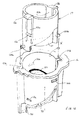
- Figure 1 shows an alternative construction in detailed cross-section through the recess 16 and stabilizer 10 when the stabilizer is in the retracted position.
- the locking tabs 52a,b each have a retention tab 12a,b protruding therefrom.
- This retention tab 12a,b engages with retention slot 13 when the stabilizer is retracted, or with the extension slot 14 when the stabilizer is in an extended stabilizing position.
- the locking controls 11a and 11b are compressed together in the direction A shown in figure 1, the retention tabs 12a,b disengage from the retention slots 13a,b and the compressed spring 15 pushes the engagement portion 17 out of the recess 55.
- the retention tabs 12a,b snap into the extension slot 14.
- the position and configuration of the extension slot 14 may be such as to allow the stabilizer to rotate freely around an axis defined by the engagement portion 17 or only to lock when the stabilizer is rotated at right angles to the casing as in figure 5.
- the extension slot 14 may have a stepped or two-stage locking shape including a shallow slot (not shown) running around the lip of the recess 55. This can be used to initially lock the stabilizer axially in the recess, but then allow it to rotate until it is in the stabilizing orientation whereby the retention tabs 12a,b snap into a secondary deeper locking slot (not shown).
- This two-stage locking mechanism may be desirable as it provides two levels of locking, the first on extraction of the stabilizer 10 from the casing so it can be rotated, and the second level corresponding to locking the stabilizer 10 into position at right-angles to the casing front-back axis.
- the sequence is reversed.
- the user compresses the two locking controls 11a and 11b, rotates the stabilizer into the retraction position and pushes the stabilizer 10 into the recess 16.
- FIG. 8 Another embodiment of the engagement means 17 and corresponding engagement recess 55 is illustrated in figures 8 to 11. This embodiment provides a stronger construction than that previously described and may be used instead of, or in combination with, the alternative embodiments of the retention slot 14 described above.
- the engagement means 17 includes a partial thread 114 with a land 112 and 116 at either end.
- This partial thread 114 is formed by molding a cut away section 111 into the side wall of the engagement means 17.
- a corresponding partial thread is formed in the inside of the engagement surface 55.
- Each partial thread has a corresponding partner on the opposite side of the engagement means 17.
- the pairs of partial threads are shown by the dotted and solid outlines in Figure 8 and 9 respectively.
- the partial thread 115 in the engagement surface 55 coacts with the partial thread 114 formed in the engagement means 17 so as to cause the engagement means to rotate as it enters into the engagement recess 55.
- the surface 16 and the foot 10 are omitted for clarity in these two figures.
- the engagement means 17 engages with the thread 115 so that the land 112 rests on top of the land 113.
- Land 116 rests on the lower surface of the recess 55.
- the interaction between the thread surfaces 115 and 114 result in the foot moving axially out of the recess 55.
- the land 116 rests on the land 113.
- the retention tabs 12a,b snap into retention slots 14a,b and the weight of the PC thus rests, via the lands, on the molded interior of the surface 55.
- This construction will be significantly stronger that the situation described above where the full weight of the computer rests on the retention tabs.
- the molding in the engagement recess can be strengthened to suit the weight of the computer if desired.
- FIG. 10 An underside view of the engagement means 17 prior to insertion into the engagement surface 55 is shown in figures 10 and 11.
- the partial thread formed by the surfaces 111, 114 of the engagement means 17 is visible as is the partial thread formed by the surfaces 115, 110 of the engagement recess 55.
- the retention tabs 12a,b slide down the inside surface of the engagement recess 55.
- the partial threads cause it to rotate into a position whereby the retention tabs 12a,b snap into the retention slots 13a,b. This secures the stabilizer 10 in the stored position.
- To extract the stabilizer the procedure outlined above is followed. Once the foot is extracted, the lands support the weight of the computer.
- FIG. 12 A further embodiment is shown in figure 12.
- the engagement means 17 is inserted into the engagement recess 55 as shown by the arrows X in figure 12.
- the posts 120a,b engage with slots 121a,b.
- the slots 121a,b and are oriented and function as follows.
- the stabilizer 10 may be inserted into the recess 16.
- the posts are positioned so that they become free of the slots 121a,b. This is shown in figure 12, lower left.
- the foot In this position, the foot is free to rotate slightly (anticlockwise when viewed from above), so that the post 120a rests against a portion 150. At this point, the foot may be slightly withdrawn whereby the post slides up the portion 150 and engages with the slot 122. If the foot 10 is withdrawn, either by manually or by means of a spring (not shown), the posts slide along slots 122. This causes the stabilizer 10 to rotate into the stabilizing orientation without the user manually rotating the stabilizer 10. When the stabilizer is properly oriented in the stabilizing position, the posts are aligned at the upper end of the slot 122. In this configuration, the engagement means including the partial thread operates as described above so that the weight of the PC is supported on the lands.
- a spring (not shown) may be used to bias the engagement means so that the overall effect is that when the user presses the engagement controls 11a,b together, the foot “automatically” extends and rotates into the required position and when the stabilizer is pressed axially into the recess 16, it rotates and retracts 'automatically'.
- the orientation of the post, the portion, the locking tab 52 and the bottom of the slot 122 causes the post to be 'trapped' in the slot after its' initial insertion into the recess 55.
- the foot can be rotated backwards and then pulled out. This allows the post 120a,b to travel back up the slot 121a,b thereby releasing the foot 10. This operation would depend on the relative orientations and dimensions between the post 120a,b and the slot 122a,b at the bottom right of the illustration in figure 12.
- the stabilizing means of the invention there are numerous possible shapes and configurations for the stabilizing means of the invention. Further, although a particular example has been shown with a single stabilizer mounted toward the front of a PC (see figure 6), other configurations of stabilizers, including multiple stabilizers, are possible. Further, the stabilizer itself may be constructed with a different shape or proportion.
- control tab etc may be contemplated depending on the overall design of the PC and the particular style which is desired.
- the locking slots may be constructed so as to have a two-stage locking and rotating action as well as 'automatic' extension and positioning functionality. This would depend on the type of retraction and locking that is required.
- Different locking tab constructions and biasing techniques may be possible which incorporate outwardly oriented key and keyway constructions biased by springs.
- the present invention provides for an aesthetically appealing and compact design for a stabilizing mount for a computer. It is readily adaptable to modification to satisfy different designs and appearances. Multiple stabilizing mounts may be used and the invention an also be applied to similarly shaped and oriented computer hardware. A further advantage is that the foot can be universal as different computers can use the same integrated foot parts.
Abstract
Description
- The present invention relates to apparatus for mounting and/or stabilizing computers and computer related hardware. More particularly, although not exclusively, this invention relates to devices for mounting and/or stabilizing desktop, portable and small form-factor computers in orientations which ensure that necessary operating functions such as cooling etc are not compromised.
- Traditional designs for personal computers have evolved from the 'standard' personal computer, exemplified by the IBM-AT, to small form-factor PCs such as the e-PC manufactured by Hewlett Packard Company. This design development has resulted in many innovative and creative designs solutions reflecting the acceptance of such hardware in the business and home environment. This evolution in design has also been influenced by aesthetic considerations which were previously considered secondary to the basic task of housing the internal computer hardware in a functional casing unit.
- Early types of personal computers were generally characterized by a horizontally mounted motherboards resulting in a quite low case profile with a relatively large footprint. This was necessitated by the PC case needing to be sufficiently large to accommodate motherboard, disk drives, power supplies etc. Early expansion board topologies reinforced the popularity of this type of case construction. However such designs consumed a significant amount of desk or floor space and a number of design solutions were proposed to reduce the PC footprint.
- Early adaptations of known PC designs aimed at reducing the PC footprint included mounting the PC case on its side. Such solutions often involved simply tilting a standard PC on its edge, or constructing the case and chassis in a vertical orientation. Designs of the latter type are referred to as 'tower' configurations and sometimes involve the redesign of the computers internal hardware topology to accommodate this orientation.
- A common problem with such configurations is that upright or slim line computer cases can be unstable and prone to tipping over. This is particularly so when the computer is located on the floor or perhaps where additional hardware components, for example external disk drives etc, are located on top of the computer case.
- Early simple solutions included providing a separate resilient plastic 'foot' device in the form of a cradle into which the edge-mounted PC case could be slid. Such designs are not ideal as PC cases come in a variety of dimensions and not all feet can accommodate every model of PC. Other solutions include integrally molding into the base of the tower case, an outwardly oriented flange or rim. Others include incorporating molded or extruded rails mounted along the edge of the computer casing to extend the footprint slightly. Such methods can increase the footprint and improve stability. However, they may not be ideal as they often do not provide sufficient stability and flexibility in terms of operating functions (cooling etc). These modifications can also interfere with aesthetic aspects or the casing as well as hamper the ability to quickly and easily reorient the computer in a horizontal or vertical position.
- More recent solutions include stabilizer constructions in the form of a casing-wall section which, when rotated, extends the casing face outwardly forming a flat "foot" protruding from either side of the machine. This configuration leaves the computer case flush with the floor or desktop and requires significant engineering to incorporate the pivoting foot into the casing wall. Further, the construction of this type of foot is such that its' width (in the lateral direction of the PC case), is approximately the same as the height of the PC case when the case is lying flat. This width does not contribute to the stability of the PC case when the foot is extended and may complicate the internal construction of the case. Such a construction may also be problematic in situations where cooling vents or intakes would be obscured when the PC is mounted in the upright or vertical position with the foot extended. The foot construction described above does not allow through-wall cooling of components located adjacent the lower PC case wall.
- Very small footprint PCs such as the e-PC manufactured by Hewlett Packard Company, are constructed with a relatively flat profile and can be oriented vertically or horizontally. The stability of such computers can be enhanced with careful distribution of weight via component location within the casing. However it remains desirable to augment the stability of such computer form-factors with additional stabilizing devices. As noted above, separate foot components may be used, however these can suffer the same drawbacks as for PCs with conventional dimensions.
- It is an object of the present invention to provide for a means and device for stabilizing a PC or computer equipment which is aesthetically pleasing, non-intrusive, compact, solid, easy to retract/extend and which allows through-wall cooling through the underside of the vertically mounted computer or hardware component casing.
- In one aspect the present invention provides for a chassis cover for a unit having a horizontal and vertical orientation, the chassis cover preferably including:
- at least one wall panel incorporating a recess;
- a stabilizer adapted to be located in the recess, where the recess is adapted so that in a retracted position the stabilizer is substantially contained within the recess and, in an extended position, the stabilizer extends from the recess in such a way so as to stabilize the chassis when the chassis is mounted in a vertical orientation, wherein the stabilizer may be moved into and locked into the stabilizing position by means of a combined extension and rotation action.
- The stabilizer may be mounted within the recess by means of an engagement portion adapted to engage with a correspondingly shaped engagement surface in the recess.
- The engagement portion is preferably in the shape of a cylinder.
- The engagement portion may incorporate at least one locking means which, when the stabilizer is in the retracted configuration, engages with a corresponding first retention means in the engagement surface and, when in the stabilizer is in an extended configuration, engages with corresponding second retention means in the engagement surface.
- The locking means preferably corresponds to a locking tab.
- The first and second retention means may correspond to slots, surfaces or other features adapted to releasably engage with the locking means when said locking means is moved into a first and second engagement position respectively.
- The one or more locking means may be biased so that when said locking means are in registration with the first or second retention means, it is biased into engagement with the first or second retention means respectively.
- The one or more locking means may preferably be adapted to engage with the first and second retention means by means of at least one protruding retention tab which is adapted to removably engage with said first and second retention means in the engagement surface.
- The one or more locking means are preferably adapted so that they each include a locking control which:
- when operated in the retracted position, disengages the one or more locking means from corresponding first retention means thereby allowing the stabilizer to be extracted from the recess and locked into the stabilizing position by means of biased engagement of the locking means with corresponding second retention means; and
- when operated in the stabilizing position, disengages the one or more locking means from corresponding second retention means thereby allowing the stabilizer to be inserted into the recess and locked into the retracted position by means of biased engagement of the one or more locking means with corresponding first retention means.
- The engagement portion may be hollow and the one or more locking means formed from partially cut away sections shaped so as to form a hinge section adjacent an inner end of the engagement portion and the locking control adjacent an outer end of the engagement portion.
- Ideally there are two locking means located on opposite sides of the engagement means.
- The second retention means preferably incorporates a first and second stage locking mechanism adapted so that when the locking means engages with the first stage locking mechanism it is fixed in the extended position but able to rotate substantially freely and when the stabilizer is rotated into a predetermined position it engages with the second stage locking mechanism and is locked in place.
- The first and second stage locking mechanism preferably correspond to recessed slots having first and second depths respectively and where the first slot extends around an inner surface of the engagement surface so that when the locking means is engaged with the second stage locking mechanism the stabilizer is capable of free rotational movement.
- The second stage locking mechanism preferably corresponds to a slot of second, deeper, depth adapted and located so that when the stabilizer is rotated into the stabilizing position it engages with the second stage locking mechanism.
- The stabilizing position preferably corresponds to the stabilizer being oriented at substantially 90 degrees to a plane defined by the unit when in the vertical position.
- In an alternative embodiment, the stabilizer and the recess may each incorporate threaded sections adapted to engage in such a way that when the stabilizer is inserted into the recess, it rotates into a storage position without any user intervention.
- Each threaded section may incorporate at least one land adapted to transmit the weight of the unit to the stabilizer when the stabilizer is in the stabilizing position.
- The engagement means as hereinbefore defined preferably has a partial thread formed therein and adapted to engage in a slideable rotating engagement with a corresponding partial thread in the engagement surface.
- Each partial thread preferably includes a corresponding land which, in the stabilizing position, serves to transmit the weight of the unit to the foot.
- The lands are preferably in the form of substantially flat portions of the partial thread, oriented and positioned to provide coacting bearing surfaces when the unit is in the stabilizing position.
- In yet an alternative embodiment, the stabilizer may include at least one post and the recess includes at least one corresponding first slot, the post and first slot adapted to engage so as to orient and position the stabilizer in both the retracted and stabilized position depending on the degree of retraction of the stabilizer from the recess.
- Such a stabilizer preferably incorporates two posts and the recess two corresponding slots, wherein the posts and slots are arranged so that as the stabilizer is extracted from the recess, it rotates from the retracted position into the stabilized position.
- The slots preferably form a helical path which causes the stabilizer to rotate as it traverses the engagement recess.
- Preferably the chassis cover includes second slots traversing the length of the recess and adapted to allow the stabilizer to be located in the recess whereupon a small rotation of the stabilizer causes the posts to engage with the corresponding first slots.
- The second slots may be positioned so that the posts do not re-engage with the first slots if the stabilizer is retracted in a non-rotating manner.
- The chassis cover may include a biasing means adapted to bias the stabilizer out of the recess.
- The invention also provides for a stabilizer for a computer which is adapted to be located in a recess in a computer casing such that in a retracted position the stabilizer is substantially contained within the recess and, in an extended position, the stabilizer extends from the recess in such a way so as to stabilize the chassis when the computer is mounted in a vertical orientation, wherein the stabilizer is adapted so that it is moved into and locked into the stabilizing position by means of a combined extension and rotation action.
- The stabilizer may include an engagement portion which is adapted to engage with a correspondingly shaped engagement surface in the recess.
- The engagement portion is preferably in the shape of a cylinder.
- The engagement portion preferably incorporates at least one locking means which is adapted so that when the stabilizer is in the retracted configuration, engages with a corresponding first retention means in the engagement surface and, when in the stabilizer is in an extended configuration, engages with a corresponding second retention means in the engagement surface.
- The locking means preferably corresponds to a locking tab.
- The one or more locking means is preferably biased so that when said one or more locking means are in registration with the first or second retention means, the one or more locking means are biased into engagement with the first or second retention means respectively.
- The one or more locking means preferably is adapted to engage with the first and second retention means by means of at least one protruding retention tab which is adapted to removably engage with said first and second retention means in the engagement surface.
- Preferably the one or more locking means include a locking control which:
- when operated in the retracted position, disengages the one or more locking means from corresponding first retention means thereby allowing the stabilizer to be extracted from the recess and locked into the stabilizing position by means of biased engagement of the locking means with corresponding second retention means; and
- when operated in the stabilizing position, disengages the one or more locking means from corresponding second retention means thereby allowing the stabilizer to be inserted into the recess and locked into the retracted position by means of biased engagement of the one or more locking means with corresponding first retention means.
- The engagement portion is preferably hollow and the one or more locking means are preferably formed from partially cut away sections shaped so as to form a hinge section adjacent a distal end of the engagement portion and the locking control adjacent an proximal end of the engagement portion.
- The stabilizer as hereinbefore defined preferably includes two locking means located on opposite sides of the engagement means.
- Preferably the second retention means incorporates a first and second stage locking mechanism adapted so that when the one or more locking means engages with the first stage locking mechanism the stabilizer is fixed in the extended position but able to rotate substantially freely and when the stabilizer is rotated into a predetermined position in relation to the recess, it engages with the second stage locking mechanism and is locked in place.
- The first and second stage locking mechanism preferably corresponds to recessed slots having first and second depths respectively, where the first slot extends around an inner surface of the engagement surface so that when the one or more locking means is engaged with the first stage locking mechanism the stabilizer is capable of free rotational movement.
- The second stage locking mechanism preferably corresponds to a slot of second, deeper, depth adapted and located so that when the stabilizer is rotated into the stabilizing position it engages with the second stage locking mechanism and is locked in place.
- The stabilizing position preferably corresponds to the stabilizer being oriented at substantially 90 degrees to a plane defined by the computer when in the vertical position.
- The stabilizer as hereinbefore defined may be adapted for use with a chassis as hereinbefore defined.
- The present invention will now be described by way of example only and with reference to the drawings in which:
- Figure 1:
- illustrates a cross section in a lateral direction through a stabilizer and a side wall when the stabilizer is in a retracted position;
- Figure 2:
- illustrates an underside perspective of a side wall with a stabilizer in a retracted position;
- Figure 3:
- illustrates an underside perspective of a side wall with a stabilizer in an extended position;
- Figure 4:
- illustrates an underside plan view (a) of a sidewall incorporating a stabilizer and, side view (b) and side cross-section view (c) of a stabilizer;
- Figure 5:
- illustrates an exploded perspective view of a stabilizer and sidewall with recess;
- Figure 6:
- illustrates a perspective view of a stabilizer in an extended position and a PC case stabilized by a stabilizer;
- Figure 7:
- illustrates retracting and extending a stabilizer;
- Figure 8;
- illustrates a see-through view of an embodiment of a male part of an engagement means;
- Figure 9:
- illustrates a see-through view of an embodiment of a female part of an engagement means corresponding to the part shown in figure 8;
- Figure 10:
- illustrates a perspective view of an embodiment of a male part of an engagement means from below;
- Figure 11:
- illustrates a perspective view of an embodiment of a female part of an engagement means corresponding to the part shown in figure 10;
- Figure 12:
- illustrates a see-through view of a further embodiment of an engagement means including a location and locking slot.
- The right hand portion of figure 6 illustrates a design of
computer 60 to which the present invention may be usefully applied. As discussed in the preamble to this specification, personal computers including those with small form factors are desirably oriented in a vertical position as shown in figure 6. The dimensions of such casing configurations and the mass of the desktop computer units are such that they can be easily tipped over and in cases where the casing cannot be arranged horizontally, some form of vertical stabilization is necessary. - Referring to figures 2 and 3, a
stabilizer 10 in accordance with a preferred embodiment of the invention is shown in the extended (figure 3) and retracted (figure 2) position. This embodiment corresponds to a simplified and generalized implementation of the present invention and it is noted that refinements including aesthetic and constructional variations are to be considered within the scope of the invention. - The stabilizer has a general construction whereby a foot (18a, 18b) may be stored in a retracted position (see figure 2) in the base of a computer casing 20 (see figure 3). In this configuration, the
stabilizer 10 is rotated so as to be congruent a suitably shaped recess 16 (see figure 3). In the stabilizing position, thestabilizer 10 is extended from thesidewall recess 16 and rotated in a plane parallel to the sidewall surface as shown in figure 3. A preferred and generally most stable configuration corresponds to that where the stabilizer foot (18a, 18b) is oriented perpendicularly to the lengthwise, or front-back axis, of the PC casing. This configuration can be seen from the underside in figures 3 and 6. - The locking state of the
stabilizer 10 is controlled by means of an engagement portion, generally indicated by the numeral 17 in figure 5. The engagement portion has lockingcontrols stabilizer 10. - This feature can be seen more clearly in the simplified embodiment illustrated in figures 4a,b and c. Here the
stabilizer 10 is generally rectangular in shape and includesfeet controls 11a,b adjacent the central engagement portion (not visible). - Figure 5 illustrates a detailed example of a preferred embodiment of the present invention. The construction shown is a preferred example only and there may be other shapes and stabilizer arrangements which, while embodying the present invention, satisfy design, aesthetic and other requirements.
- Referring to figure 5 a
stabilizer 10 includesfeet pad combinations 18a,b and 50a,b form the stabilizing elements which stabilize the computer on its mounting surface. - The
engagement portion 17 protrudes into and through the casing and engages with a correspondingly shaped engagement recess 55 (see figure 5). In a preferred embodiment, theengagement portion 17 is a substantially right-cylindrical member 17 out of which twoelongate locking tabs tab 52b is obscured in figure 5. - As can be seen in figure 5, the locking
tabs 52a,b are formed by cutting away portions of the side-walls of thecylindrical engagement portion 17 so that a bendable hinge portion 56a is formed at the end which connects the locking tabs 51a,b to theengagement portion 17. The lockingtabs 52a,b are therefore oriented in a direction which is perpendicular to the plane of the side wall and can be operated by pressing the locking controls 11a and 11b in the direction F and F' respectively in figure 5. - The
recess 16 in the sidewall is shaped to receive thestabilizer 10 as a whole so that when thestabilizer 10 is in the retracted position, the undersides of the pads 50a and 50b lie flush with or below the plane of the sidewall. In the retracted (and locked) position, thestabilizer 10 is oriented in the position shown in figure 5, parallel to the front-back axis of the computer casing. - The
stabilizer 10 is substantially constrained within the recess defined by thesurface 16 when theengagement portion 17 is fully inserted and locked into the correspondingly shapedengagement surface 55. In the present geometry, theengagement surface 55 is a recessed, open cavity such as that shown in figure 5. Alternatively, it may include a cylindrical central pillar section as illustrated bycomponent 26 in figure 1. This latter construction is possibly stronger and, under certain circumstances, can help to center a suitably shapedengagement portion 17 within theengagement surface 55. Alternatively, theengagement portion 17 may protrude through a hole 27 (see figure 5) in the engagement surface. This allows sufficient lengthwise clearance so that in the retracted position theretention tabs 12a,b can engage with theircorresponding retention slots 13a,b. Of course the depth of theengagement recess 55 and the length of theengagement portion 17 may vary depending on the specific construction of the foot locking mechanism. - Locking and unlocking the
stabilizer 10 is described as follows. - When the
stabilizer 10 is retracted into therecess 16 in the orientation shown in figure 5,retention tabs locking tabs 52a,b engage withretention slots engagement recess 55. - In a preferred embodiment, this engagement is a snap-action resulting from a biasing force provided by flexing the
locking tabs 52a,b around their corresponding hinge portions 56a,b. That is, when the stabilizer is inserted into the recess, theretention tabs 12a,b slide along the sides of theengagement surface 55 until they reach theretention slots 13a,b. At this point the outward biasing force causes theretention tabs 12a,b to snap outwardly into theircorresponding retention slots 13a,b. The biasing force then locks theretention tabs 12a,b in engagement with theretention slots 13a,b. - This secures the
stabilizer 10 within the recess in the retracted position. - To extract and extend the stabilizer, the locking controls 11a and 11b are pressed inwardly as shown in figure 7. This bends the
locking tabs 52a,b and disengages theretention tabs 12a,b from theretention slots 13a,b. The stabilizer may then be slightly withdrawn from therecess 16 and rotated as shown by D in figure 7. As the stabilizer is withdrawn and rotated, theretention tabs 12a,b come into engagement withextension slots 14a,b. These are shown in figure 5 assingle slots 14a,b which engage theretention tabs 12a,b when the stabilizer is withdrawn and rotated at right angles to the long axis of the PC case. In another embodiment (seen in cross section in figure 1), theextension slots 14a,b may extend completely around the lip of therecess 55. In this configuration thestabilizer 10, once withdrawn, locks into a fixed axial position in relation to the plane of the sidewall and may then be rotated into the desired stabilizing position (i.e.; through 90 degrees). - A spring 15 may be used to bias the
stabilizer 10 out of therecess 16 so that when the user compresses the locking controls 11a and 11b, the stabilizer automatically "ejects" and then locks by means of theretention tabs 12a,b engaging withextension slots 14a,b in the rotatable or fixed stabilizing position shown in figure 7, bottom right. - Figure 1 shows an alternative construction in detailed cross-section through the
recess 16 andstabilizer 10 when the stabilizer is in the retracted position. - Referring to figure 1, and as described above, the locking
tabs 52a,b each have aretention tab 12a,b protruding therefrom. Thisretention tab 12a,b engages with retention slot 13 when the stabilizer is retracted, or with theextension slot 14 when the stabilizer is in an extended stabilizing position. When the locking controls 11a and 11b are compressed together in the direction A shown in figure 1, theretention tabs 12a,b disengage from theretention slots 13a,b and the compressed spring 15 pushes theengagement portion 17 out of therecess 55. As theengagement portion 17 and stabilizer move out of the recess, theretention tabs 12a,b snap into theextension slot 14. The position and configuration of theextension slot 14 may be such as to allow the stabilizer to rotate freely around an axis defined by theengagement portion 17 or only to lock when the stabilizer is rotated at right angles to the casing as in figure 5. - In an alternative embodiment, the
extension slot 14 may have a stepped or two-stage locking shape including a shallow slot (not shown) running around the lip of therecess 55. This can be used to initially lock the stabilizer axially in the recess, but then allow it to rotate until it is in the stabilizing orientation whereby theretention tabs 12a,b snap into a secondary deeper locking slot (not shown). This two-stage locking mechanism may be desirable as it provides two levels of locking, the first on extraction of thestabilizer 10 from the casing so it can be rotated, and the second level corresponding to locking thestabilizer 10 into position at right-angles to the casing front-back axis. The operation of this embodiment is shown schematically in figure 7, where the stabilizer is retracted in the direction C, whereupon theretention tabs 12a,b snap into an annular (first) recess. On rotating thestabilizer 10 in the direction D, theretention tabs 12a,b then snap into a (second) recess. This fixes thestabilizer 10 axially and laterally in the position shown in figure 6. - To retract the
stabilizer 10, the sequence is reversed. The user compresses the two lockingcontrols stabilizer 10 into therecess 16. - Another embodiment of the engagement means 17 and
corresponding engagement recess 55 is illustrated in figures 8 to 11. This embodiment provides a stronger construction than that previously described and may be used instead of, or in combination with, the alternative embodiments of theretention slot 14 described above. - Referring to figures 8 and 9, the engagement means 17 includes a
partial thread 114 with aland partial thread 114 is formed by molding a cut away section 111 into the side wall of the engagement means 17. A corresponding partial thread is formed in the inside of theengagement surface 55. This is shown in figure 9. Each partial thread has a corresponding partner on the opposite side of the engagement means 17. For example, the pairs of partial threads are shown by the dotted and solid outlines in Figure 8 and 9 respectively. Thepartial thread 115 in theengagement surface 55 coacts with thepartial thread 114 formed in the engagement means 17 so as to cause the engagement means to rotate as it enters into theengagement recess 55. Thesurface 16 and thefoot 10 are omitted for clarity in these two figures. - When the
stabilizer 10 is configured in the recessed position, the engagement means 17 engages with thethread 115 so that theland 112 rests on top of theland 113.Land 116 rests on the lower surface of therecess 55. When thestabilizer 10 is rotated anticlockwise (when viewed from above), the interaction between the thread surfaces 115 and 114 result in the foot moving axially out of therecess 55. Once the foot is oriented at, for example, 90 degrees to its' stored orientation, theland 116 rests on theland 113. Theretention tabs 12a,b snap intoretention slots 14a,b and the weight of the PC thus rests, via the lands, on the molded interior of thesurface 55. This construction will be significantly stronger that the situation described above where the full weight of the computer rests on the retention tabs. In certain situations, the molding in the engagement recess can be strengthened to suit the weight of the computer if desired. - An underside view of the engagement means 17 prior to insertion into the
engagement surface 55 is shown in figures 10 and 11. Here the partial thread formed by thesurfaces 111, 114 of the engagement means 17 is visible as is the partial thread formed by thesurfaces engagement recess 55. When thestabilizer 10 as a whole, is pressed into therecess 16, theretention tabs 12a,b slide down the inside surface of theengagement recess 55. As the stabilizer is pushed into theengagement recess 55, the partial threads cause it to rotate into a position whereby theretention tabs 12a,b snap into theretention slots 13a,b. This secures thestabilizer 10 in the stored position. To extract the stabilizer, the procedure outlined above is followed. Once the foot is extracted, the lands support the weight of the computer. - A further embodiment is shown in figure 12. According to this embodiment,
posts 120a,b and provided to assist in rotating and locating theengagement 17 means and thus thestabilizer 10 in the correct orientation in theengagement recess 55 for both storage and in the support position. During assembly of the computer casing, the engagement means 17 is inserted into theengagement recess 55 as shown by the arrows X in figure 12. Theposts 120a,b engage withslots 121a,b. Theslots 121a,b and are oriented and function as follows. When the posts are inserted into the slots, thestabilizer 10 may be inserted into therecess 16. At a point where the foot is just short of being fully retracted, the posts are positioned so that they become free of theslots 121a,b. This is shown in figure 12, lower left. In this position, the foot is free to rotate slightly (anticlockwise when viewed from above), so that thepost 120a rests against aportion 150. At this point, the foot may be slightly withdrawn whereby the post slides up theportion 150 and engages with theslot 122. If thefoot 10 is withdrawn, either by manually or by means of a spring (not shown), the posts slide alongslots 122. This causes thestabilizer 10 to rotate into the stabilizing orientation without the user manually rotating thestabilizer 10. When the stabilizer is properly oriented in the stabilizing position, the posts are aligned at the upper end of theslot 122. In this configuration, the engagement means including the partial thread operates as described above so that the weight of the PC is supported on the lands. A spring (not shown) may be used to bias the engagement means so that the overall effect is that when the user presses the engagement controls 11a,b together, the foot "automatically" extends and rotates into the required position and when the stabilizer is pressed axially into therecess 16, it rotates and retracts 'automatically'. - The orientation of the post, the portion, the locking tab 52 and the bottom of the
slot 122 causes the post to be 'trapped' in the slot after its' initial insertion into therecess 55. To remove the stabilizer from the casing, the foot can be rotated backwards and then pulled out. This allows thepost 120a,b to travel back up theslot 121a,b thereby releasing thefoot 10. This operation would depend on the relative orientations and dimensions between thepost 120a,b and the slot 122a,b at the bottom right of the illustration in figure 12. - There are numerous possible shapes and configurations for the stabilizing means of the invention. Further, although a particular example has been shown with a single stabilizer mounted toward the front of a PC (see figure 6), other configurations of stabilizers, including multiple stabilizers, are possible. Further, the stabilizer itself may be constructed with a different shape or proportion.
- Similarly, other shapes of control tab etc may be contemplated depending on the overall design of the PC and the particular style which is desired. As noted above, the locking slots may be constructed so as to have a two-stage locking and rotating action as well as 'automatic' extension and positioning functionality. This would depend on the type of retraction and locking that is required. Different locking tab constructions and biasing techniques may be possible which incorporate outwardly oriented key and keyway constructions biased by springs.
- Thus it can be seen that the present invention provides for an aesthetically appealing and compact design for a stabilizing mount for a computer. It is readily adaptable to modification to satisfy different designs and appearances. Multiple stabilizing mounts may be used and the invention an also be applied to similarly shaped and oriented computer hardware. A further advantage is that the foot can be universal as different computers can use the same integrated foot parts.
- Although the invention has been described by way of example and with reference to particular embodiments it is to be understood that modification and/or improvements may be made without departing from the scope of the appended claims.
- Where in the foregoing description reference has been made to integers or elements having known equivalents, then such equivalents are herein incorporated as if individually set forth.
Claims (16)
- A chassis cover for a unit having a horizontal and vertical orientation, the chassis cover including:at least one wall panel incorporating a recess;a stabilizer adapted to be located in the recess, where the recess is adapted so that in a retracted position the stabilizer is substantially contained within the recess and, in an extended position, the stabilizer extends from the recess in such a way so as to stabilize the chassis when the chassis is mounted in a vertical orientation, wherein the stabilizer is moved into and locked into the stabilizing position by means of a combined extension and rotation action.
- A chassis cover as claimed in claim 1 wherein the stabilizer is mounted within the recess by means of an engagement portion adapted to engage with a correspondingly shaped engagement surface in the recess.
- A chassis cover as claimed in claim 2 wherein the engagement portion incorporates at least one locking means which, when the stabilizer is in the retracted configuration, engages with a corresponding first retention means in the engagement surface and, when in the stabilizer is in an extended configuration, engages with corresponding second retention means in the engagement surface.
- A chassis cover as claimed in claim 3 wherein the one or more locking means is biased so that when said locking means are in registration with the first or second retention means, they are biased into engagement with the first or second retention means respectively.
- A chassis cover as claimed in either claim 3 or 4 wherein the one or more locking means engage with the first and second retention means by means of at least one protruding retention tab which is adapted to removably engage with said first and second retention means in the engagement surface.
- A chassis cover as claimed in any one of claims 3 to 5 wherein the one or more locking means are adapted so that they each include a locking control which:when operated in the retracted position, disengages the one or more locking means from corresponding first retention means thereby allowing the stabilizer to be extracted from the recess and locked into the stabilizing position by means of biased engagement of the locking means with corresponding second retention means; andwhen operated in the stabilizing position, disengages the one or more locking means from corresponding second retention means thereby allowing the stabilizer to be inserted into the recess and locked into the retracted position by means of biased engagement of the one or more locking means with corresponding first retention means.
- A chassis cover as claimed in any one of claims 3 to 6 wherein the second retention means incorporates a first and second stage locking mechanism adapted so that when the locking means engages with the first stage locking mechanism it is fixed in the extended position but able to rotate substantially freely so that when the stabilizer is rotated into a predetermined position it engages with the second stage locking mechanism and is locked in place.
- A chassis cover as claimed in any one of claims 1 to 7 wherein the stabilizer and the recess each incorporate threaded sections adapted to engage in such a way that when the stabilizer is inserted into the recess, it rotates into a storage position without any user intervention.
- A chassis cover as claimed in any one of claims 2 to 8 wherein the engagement means has a partial thread formed therein and adapted to engage in a slideable rotating engagement with a corresponding partial thread in the engagement surface.
- A chassis cover as claimed in either claim 8 or 9 wherein each threaded section incorporates at least one land adapted to transmit the weight of the unit to the stabilizer when the stabilizer is in the stabilizing position.
- A chassis cover as claimed in any one of claims 8 to 10 wherein the stabilizer includes at least one post and the recess includes at least one corresponding first slot, there preferably being two posts and two first slots located on opposite sides of the engagement means, the post and first slot adapted to engage so as to orient and position the stabilizer in both the retracted and stabilized position depending on the degree of retraction of the stabilizer from the recess.
- A chassis cover as claimed in claim 11 wherein the first slots form a helical path which causes the stabilizer to rotate as it traverses the recess.
- A chassis cover as claimed either of claims 11 to 12 including second slots traversing the length of the recess and adapted to engage corresponding posts so as to orient the stabilizer for location in the recess whereupon a small rotation of the stabilizer causes the posts to engage with the corresponding first slots.
- A chassis cover as claimed in claim 13 wherein the second slots are positioned so that the posts do not re-engage with the first slots if the stabilizer is retracted in a non-rotating manner.
- A stabilizer for a computer adapted for use with the chassis cover claimed in any one of claims 1 to 14.
- A computer incorporating the stabilizer and chassis construction claimed in any preceding claim.
Priority Applications (2)
| Application Number | Priority Date | Filing Date | Title |
|---|---|---|---|
| EP01410125.7A EP1298520B1 (en) | 2001-10-01 | 2001-10-01 | Stabilizing system for computer hardware |
| US10/262,598 US7328880B2 (en) | 2001-10-01 | 2002-09-30 | Stabilizing system for computer hardware |
Applications Claiming Priority (1)
| Application Number | Priority Date | Filing Date | Title |
|---|---|---|---|
| EP01410125.7A EP1298520B1 (en) | 2001-10-01 | 2001-10-01 | Stabilizing system for computer hardware |
Publications (2)
| Publication Number | Publication Date |
|---|---|
| EP1298520A1 true EP1298520A1 (en) | 2003-04-02 |
| EP1298520B1 EP1298520B1 (en) | 2018-02-21 |
Family
ID=8183123
Family Applications (1)
| Application Number | Title | Priority Date | Filing Date |
|---|---|---|---|
| EP01410125.7A Expired - Lifetime EP1298520B1 (en) | 2001-10-01 | 2001-10-01 | Stabilizing system for computer hardware |
Country Status (2)
| Country | Link |
|---|---|
| US (1) | US7328880B2 (en) |
| EP (1) | EP1298520B1 (en) |
Cited By (2)
| Publication number | Priority date | Publication date | Assignee | Title |
|---|---|---|---|---|
| EP1803985A3 (en) * | 2005-12-27 | 2009-05-13 | Funai Electric Co., Ltd. | Panel-type television and plasma television |
| EP2590405A1 (en) * | 2011-11-02 | 2013-05-08 | HannStar Display Corp. | Flat panel display having storable pedestal |
Families Citing this family (18)
| Publication number | Priority date | Publication date | Assignee | Title |
|---|---|---|---|---|
| CN1869498A (en) * | 2005-05-24 | 2006-11-29 | 鸿富锦精密工业(深圳)有限公司 | Retation support device and vertical device using the device |
| CN100531530C (en) * | 2005-06-18 | 2009-08-19 | 鸿富锦精密工业(深圳)有限公司 | Electronic device |
| KR100653072B1 (en) * | 2005-08-23 | 2006-12-01 | 삼성전자주식회사 | Display |
| TW200822005A (en) * | 2006-11-03 | 2008-05-16 | Benq Corp | Base for supporting apparatus |
| US7733645B2 (en) * | 2007-02-05 | 2010-06-08 | Amtran Technology Co., Ltd | Thin display structure |
| TWI333604B (en) * | 2007-05-16 | 2010-11-21 | Inventec Corp | Pressing-type pad structure and electronic device using the same |
| US20090009953A1 (en) * | 2007-07-05 | 2009-01-08 | Jou Jye Electronic Co., Ltd | Portable hard disk drive with pivotable support legs |
| US7697283B2 (en) * | 2008-01-04 | 2010-04-13 | Apple Inc. | Enclosure foot assembly and manufacture |
| TWI419639B (en) * | 2008-06-27 | 2013-12-11 | Asustek Comp Inc | Rotary supporting structure without drawing |
| US7817418B2 (en) * | 2008-10-09 | 2010-10-19 | Dell Products, Lp | Electronic device including a support member and a method of fabricating the same |
| US8345411B2 (en) * | 2010-05-21 | 2013-01-01 | Dell Products L.P. | Information handling system support member |
| US8800786B2 (en) * | 2011-12-13 | 2014-08-12 | Howard Parkins | Portable bicycle stand |
| US20150360364A1 (en) * | 2014-06-13 | 2015-12-17 | Darren Scott Douglas | Tool Board |
| CN105570628B (en) * | 2016-01-06 | 2017-12-12 | 深圳创维-Rgb电子有限公司 | A kind of Concealable base and its television set |
| CN108664079B (en) * | 2017-03-28 | 2023-10-20 | 富泰华工业(深圳)有限公司 | Anti-falling mechanism and electronic device |
| CN107795815B (en) * | 2017-09-26 | 2020-02-21 | 京东方科技集团股份有限公司 | Display panel support |
| KR102521485B1 (en) * | 2018-09-21 | 2023-04-14 | 삼성전자주식회사 | Display apparatus |
| CN109404689A (en) * | 2018-11-22 | 2019-03-01 | 安徽万源信息科技有限公司 | It is a kind of to store the display base being wholely set |
Citations (3)
| Publication number | Priority date | Publication date | Assignee | Title |
|---|---|---|---|---|
| US5388792A (en) * | 1993-09-09 | 1995-02-14 | Compaq Computer Corporation | Pivotable computer tower support foot apparatus |
| US5934774A (en) * | 1998-02-26 | 1999-08-10 | Toshiba America Information System, Inc. | Chassis cover with a stabilizing stand |
| US6288893B1 (en) * | 1999-02-04 | 2001-09-11 | Compaq Computer Corporation | Desktop computer system having reduced footprint semi-mobile CPU unit |
Family Cites Families (18)
| Publication number | Priority date | Publication date | Assignee | Title |
|---|---|---|---|---|
| US2949984A (en) * | 1956-01-26 | 1960-08-23 | Tennessee Fabricating Company | Adjustable column foot |
| US3043641A (en) * | 1958-09-26 | 1962-07-10 | De Witt W Hanmore | Adjustable supports |
| US3393846A (en) * | 1967-05-03 | 1968-07-23 | Plattner Ind Inc | Automobile jug |
| US3715996A (en) * | 1971-08-06 | 1973-02-13 | R Rolfshus | Collapsible support member |
| US3879084A (en) * | 1973-06-18 | 1975-04-22 | Ferris E Jones | Table |
| US4053082A (en) * | 1976-03-01 | 1977-10-11 | Unarco Industries, Inc. | Electrical outlet box assembly |
| US4505408A (en) * | 1983-11-29 | 1985-03-19 | Keter Plastic (Usa) Inc. | Beverage container with collapsible legs |
| US4955873A (en) * | 1988-05-06 | 1990-09-11 | Pfizer Hospital Products Group, Inc. | Stabilizing support stand |
| US5307238A (en) * | 1991-01-31 | 1994-04-26 | Rockwell International Corporation | Avionics displays system with collapsible mounting handle |
| CA2076225C (en) * | 1991-10-03 | 1997-02-25 | Tadanobu Matsumura | Earthquake-proof leg support structure of electronic apparatus |
| JPH05119885A (en) * | 1991-10-11 | 1993-05-18 | Internatl Business Mach Corp <Ibm> | Computer, keyboard device and keyboard inclining device |
| US5601219A (en) * | 1996-05-13 | 1997-02-11 | Chen; Chao Y. | Clothes hanger covered with a toy doll |
| US5865408A (en) * | 1997-04-04 | 1999-02-02 | Tyco Group S.A.R.L. | Footstand for chest drainage unit |
| US6311941B1 (en) * | 1999-07-29 | 2001-11-06 | Hewlett-Packard Company | Anti-tip device |
| US6604831B1 (en) * | 1999-12-17 | 2003-08-12 | Hewlett-Packard Development Company, L.P. | Elevatable display apparatus |
| ES2295201T3 (en) * | 2000-08-02 | 2008-04-16 | Mattel, Inc. | KEYBOARD COATING. |
| KR100395092B1 (en) * | 2001-07-27 | 2003-08-21 | 삼성전기주식회사 | A Wireless LAN Adapter |
| US6636418B1 (en) * | 2001-08-28 | 2003-10-21 | Emc Corporation | Methods and apparatus for installing electronic cabinets using improved stabilization techniques |
-
2001
- 2001-10-01 EP EP01410125.7A patent/EP1298520B1/en not_active Expired - Lifetime
-
2002
- 2002-09-30 US US10/262,598 patent/US7328880B2/en not_active Expired - Lifetime
Patent Citations (3)
| Publication number | Priority date | Publication date | Assignee | Title |
|---|---|---|---|---|
| US5388792A (en) * | 1993-09-09 | 1995-02-14 | Compaq Computer Corporation | Pivotable computer tower support foot apparatus |
| US5934774A (en) * | 1998-02-26 | 1999-08-10 | Toshiba America Information System, Inc. | Chassis cover with a stabilizing stand |
| US6288893B1 (en) * | 1999-02-04 | 2001-09-11 | Compaq Computer Corporation | Desktop computer system having reduced footprint semi-mobile CPU unit |
Non-Patent Citations (1)
| Title |
|---|
| "PIVOTING FOOT", IBM TECHNICAL DISCLOSURE BULLETIN, IBM CORP. NEW YORK, US, vol. 31, no. 6, 1 November 1988 (1988-11-01), pages 228 - 230, XP000038166, ISSN: 0018-8689 * |
Cited By (3)
| Publication number | Priority date | Publication date | Assignee | Title |
|---|---|---|---|---|
| EP1803985A3 (en) * | 2005-12-27 | 2009-05-13 | Funai Electric Co., Ltd. | Panel-type television and plasma television |
| EP2590405A1 (en) * | 2011-11-02 | 2013-05-08 | HannStar Display Corp. | Flat panel display having storable pedestal |
| US8654526B2 (en) | 2011-11-02 | 2014-02-18 | Hannstar Display Corp. | Flat panel display having storable pedestal |
Also Published As
| Publication number | Publication date |
|---|---|
| EP1298520B1 (en) | 2018-02-21 |
| US20030075664A1 (en) | 2003-04-24 |
| US7328880B2 (en) | 2008-02-12 |
Similar Documents
| Publication | Publication Date | Title |
|---|---|---|
| EP1298520B1 (en) | Stabilizing system for computer hardware | |
| KR0125094B1 (en) | Connector device | |
| US7293749B2 (en) | Self aligning foot assembly | |
| EP1917569B1 (en) | Docking station for hand held electronic devices | |
| US7894198B2 (en) | Flash memory device with a retractable plug | |
| US7110252B2 (en) | Docking station with a releasing unit | |
| US8081446B2 (en) | Notebook computer | |
| US6842337B2 (en) | Stabilizing systems for computer hardware | |
| US6929337B2 (en) | Retractable stabilizing systems for computer hardware | |
| EP1302838A1 (en) | Stabilizing system for computer hardware | |
| US6059386A (en) | Detachable computer case | |
| US8644016B2 (en) | Hard disk drive module | |
| CN113867481A (en) | Electronic equipment shell and notebook computer | |
| CN214405309U (en) | Support base and electronic equipment | |
| KR19980027496A (en) | Keyboard Mounting Structure of Portable Computer | |
| KR200221920Y1 (en) | Case inserted in computer | |
| KR930008109Y1 (en) | Rotating apparatus of lcd panel for portable computer |
Legal Events
| Date | Code | Title | Description |
|---|---|---|---|
| PUAI | Public reference made under article 153(3) epc to a published international application that has entered the european phase |
Free format text: ORIGINAL CODE: 0009012 |
|
| AK | Designated contracting states |
Kind code of ref document: A1 Designated state(s): AT BE CH CY DE DK ES FI FR GB GR IE IT LI LU MC NL PT SE TR |
|
| AX | Request for extension of the european patent |
Extension state: AL LT LV MK RO SI |
|
| 17P | Request for examination filed |
Effective date: 20030926 |
|
| AKX | Designation fees paid |
Designated state(s): DE FR GB |
|
| 17Q | First examination report despatched |
Effective date: 20050606 |
|
| 17Q | First examination report despatched |
Effective date: 20050606 |
|
| RAP1 | Party data changed (applicant data changed or rights of an application transferred) |
Owner name: HEWLETT-PACKARD DEVELOPMENT COMPANY, L.P. |
|
| GRAP | Despatch of communication of intention to grant a patent |
Free format text: ORIGINAL CODE: EPIDOSNIGR1 |
|
| RIC1 | Information provided on ipc code assigned before grant |
Ipc: F16M 11/16 20060101ALI20171114BHEP Ipc: F16M 11/10 20060101ALI20171114BHEP Ipc: G06F 1/18 20060101AFI20171114BHEP Ipc: A47B 91/02 20060101ALI20171114BHEP Ipc: F16M 11/22 20060101ALI20171114BHEP |
|
| INTG | Intention to grant announced |
Effective date: 20171130 |
|
| GRAS | Grant fee paid |
Free format text: ORIGINAL CODE: EPIDOSNIGR3 |
|
| GRAA | (expected) grant |
Free format text: ORIGINAL CODE: 0009210 |
|
| AK | Designated contracting states |
Kind code of ref document: B1 Designated state(s): DE FR GB |
|
| REG | Reference to a national code |
Ref country code: GB Ref legal event code: FG4D |
|
| REG | Reference to a national code |
Ref country code: DE Ref legal event code: R096 Ref document number: 60150768 Country of ref document: DE |
|
| REG | Reference to a national code |
Ref country code: DE Ref legal event code: R097 Ref document number: 60150768 Country of ref document: DE |
|
| PLBE | No opposition filed within time limit |
Free format text: ORIGINAL CODE: 0009261 |
|
| STAA | Information on the status of an ep patent application or granted ep patent |
Free format text: STATUS: NO OPPOSITION FILED WITHIN TIME LIMIT |
|
| 26N | No opposition filed |
Effective date: 20181122 |
|
| REG | Reference to a national code |
Ref country code: DE Ref legal event code: R119 Ref document number: 60150768 Country of ref document: DE |
|
| GBPC | Gb: european patent ceased through non-payment of renewal fee |
Effective date: 20181001 |
|
| PG25 | Lapsed in a contracting state [announced via postgrant information from national office to epo] |
Ref country code: DE Free format text: LAPSE BECAUSE OF NON-PAYMENT OF DUE FEES Effective date: 20190501 |
|
| PG25 | Lapsed in a contracting state [announced via postgrant information from national office to epo] |
Ref country code: FR Free format text: LAPSE BECAUSE OF NON-PAYMENT OF DUE FEES Effective date: 20181031 |
|
| PG25 | Lapsed in a contracting state [announced via postgrant information from national office to epo] |
Ref country code: GB Free format text: LAPSE BECAUSE OF NON-PAYMENT OF DUE FEES Effective date: 20181001 |