EP1293394A1 - Airbag gas producer - Google Patents
Airbag gas producer Download PDFInfo
- Publication number
- EP1293394A1 EP1293394A1 EP01941160A EP01941160A EP1293394A1 EP 1293394 A1 EP1293394 A1 EP 1293394A1 EP 01941160 A EP01941160 A EP 01941160A EP 01941160 A EP01941160 A EP 01941160A EP 1293394 A1 EP1293394 A1 EP 1293394A1
- Authority
- EP
- European Patent Office
- Prior art keywords
- igniter
- air bag
- gas generator
- pin
- gas
- Prior art date
- Legal status (The legal status is an assumption and is not a legal conclusion. Google has not performed a legal analysis and makes no representation as to the accuracy of the status listed.)
- Granted
Links
Images


Classifications
-
- B—PERFORMING OPERATIONS; TRANSPORTING
- B60—VEHICLES IN GENERAL
- B60R—VEHICLES, VEHICLE FITTINGS, OR VEHICLE PARTS, NOT OTHERWISE PROVIDED FOR
- B60R21/00—Arrangements or fittings on vehicles for protecting or preventing injuries to occupants or pedestrians in case of accidents or other traffic risks
- B60R21/02—Occupant safety arrangements or fittings, e.g. crash pads
- B60R21/16—Inflatable occupant restraints or confinements designed to inflate upon impact or impending impact, e.g. air bags
- B60R21/26—Inflatable occupant restraints or confinements designed to inflate upon impact or impending impact, e.g. air bags characterised by the inflation fluid source or means to control inflation fluid flow
- B60R21/264—Inflatable occupant restraints or confinements designed to inflate upon impact or impending impact, e.g. air bags characterised by the inflation fluid source or means to control inflation fluid flow using instantaneous generation of gas, e.g. pyrotechnic
- B60R21/2644—Inflatable occupant restraints or confinements designed to inflate upon impact or impending impact, e.g. air bags characterised by the inflation fluid source or means to control inflation fluid flow using instantaneous generation of gas, e.g. pyrotechnic using only solid reacting substances, e.g. pellets, powder
-
- F—MECHANICAL ENGINEERING; LIGHTING; HEATING; WEAPONS; BLASTING
- F42—AMMUNITION; BLASTING
- F42B—EXPLOSIVE CHARGES, e.g. FOR BLASTING, FIREWORKS, AMMUNITION
- F42B3/00—Blasting cartridges, i.e. case and explosive
- F42B3/10—Initiators therefor
- F42B3/12—Bridge initiators
-
- B—PERFORMING OPERATIONS; TRANSPORTING
- B60—VEHICLES IN GENERAL
- B60R—VEHICLES, VEHICLE FITTINGS, OR VEHICLE PARTS, NOT OTHERWISE PROVIDED FOR
- B60R21/00—Arrangements or fittings on vehicles for protecting or preventing injuries to occupants or pedestrians in case of accidents or other traffic risks
- B60R21/02—Occupant safety arrangements or fittings, e.g. crash pads
- B60R21/16—Inflatable occupant restraints or confinements designed to inflate upon impact or impending impact, e.g. air bags
- B60R21/26—Inflatable occupant restraints or confinements designed to inflate upon impact or impending impact, e.g. air bags characterised by the inflation fluid source or means to control inflation fluid flow
- B60R2021/26029—Ignitors
-
- B—PERFORMING OPERATIONS; TRANSPORTING
- B60—VEHICLES IN GENERAL
- B60R—VEHICLES, VEHICLE FITTINGS, OR VEHICLE PARTS, NOT OTHERWISE PROVIDED FOR
- B60R21/00—Arrangements or fittings on vehicles for protecting or preventing injuries to occupants or pedestrians in case of accidents or other traffic risks
- B60R21/02—Occupant safety arrangements or fittings, e.g. crash pads
- B60R21/16—Inflatable occupant restraints or confinements designed to inflate upon impact or impending impact, e.g. air bags
- B60R21/26—Inflatable occupant restraints or confinements designed to inflate upon impact or impending impact, e.g. air bags characterised by the inflation fluid source or means to control inflation fluid flow
- B60R21/263—Inflatable occupant restraints or confinements designed to inflate upon impact or impending impact, e.g. air bags characterised by the inflation fluid source or means to control inflation fluid flow using a variable source, e.g. plural stage or controlled output
- B60R2021/2633—Inflatable occupant restraints or confinements designed to inflate upon impact or impending impact, e.g. air bags characterised by the inflation fluid source or means to control inflation fluid flow using a variable source, e.g. plural stage or controlled output with a plurality of inflation levels
-
- B—PERFORMING OPERATIONS; TRANSPORTING
- B60—VEHICLES IN GENERAL
- B60R—VEHICLES, VEHICLE FITTINGS, OR VEHICLE PARTS, NOT OTHERWISE PROVIDED FOR
- B60R21/00—Arrangements or fittings on vehicles for protecting or preventing injuries to occupants or pedestrians in case of accidents or other traffic risks
- B60R21/02—Occupant safety arrangements or fittings, e.g. crash pads
- B60R21/16—Inflatable occupant restraints or confinements designed to inflate upon impact or impending impact, e.g. air bags
- B60R21/26—Inflatable occupant restraints or confinements designed to inflate upon impact or impending impact, e.g. air bags characterised by the inflation fluid source or means to control inflation fluid flow
- B60R21/264—Inflatable occupant restraints or confinements designed to inflate upon impact or impending impact, e.g. air bags characterised by the inflation fluid source or means to control inflation fluid flow using instantaneous generation of gas, e.g. pyrotechnic
- B60R21/2644—Inflatable occupant restraints or confinements designed to inflate upon impact or impending impact, e.g. air bags characterised by the inflation fluid source or means to control inflation fluid flow using instantaneous generation of gas, e.g. pyrotechnic using only solid reacting substances, e.g. pellets, powder
- B60R2021/2648—Inflatable occupant restraints or confinements designed to inflate upon impact or impending impact, e.g. air bags characterised by the inflation fluid source or means to control inflation fluid flow using instantaneous generation of gas, e.g. pyrotechnic using only solid reacting substances, e.g. pellets, powder comprising a plurality of combustion chambers or sub-chambers
Definitions
- the present invention relates to a gas generator for an air bag and an air bag system using the same.
- a gas generator for an air bag there are a pyrotechnic-type gas generator in which only a gas generated by combustion of a gas generating agent is used for inflating an air bag and a hybrid-type gas generator in which a gas generated by combustion of a gas generating agent and a pressurized medium are used for inflating the air bag. Then, in the gas generator for the air bag used therefor, an ignition means provided with an igniter is employed as a means for generating a gas, and a single-type gas generator with one igniter and a dual-type gas generator with two igniters are used at present.
- two conductive pins (a center pin and a grounding pin) of the positive electrode and the negative electrode are provided in the respective igniters.
- a priming is ignited and burnt at conductive wires (namely, heat generating wires, electric resistance wires or the like), which connect the two conductive pins, in the course of current flows from the positive electrodes to the negative electrodes and the gas generating agents are burnt, in some cases, through ignition and burning of transfer charges.
- An object of the present invention is to provide a gas generator for an air bag in which an erroneous activation of a second igniter due to an actuation of a first igniter can be prevented and reliability as an article is enhanced, and an air bag system using the same.
- the present invention provides a gas generator for an air bag which comprises, in a housing having a gas discharging port, an ignition means provided with first and second igniters including a priming activated by the impact, and a gas generating means ignited and burnt by the ignition means to generate a combustion gas, wherein the first and second igniters are mounted to the housing via a holder; and in the second igniter, a center pin is connected to an external power supply to constitute the positive electrode, a grounding pin is connected to a metal portion of a motor vehicle to constitute the negative electrode, and an opening/shutting means of current is provided between the center pin and the external power supply.
- the second igniter constituting the ignition means can be adjusted to be activated simultaneously with the first igniter or to be activated after the first igniter is activated.
- the grounding pin and the center pin are connected to each other by a conductive wire (that is, a heat generating wire, an electric resistance wire or the like) at positions where one end portions thereof contact with priming, and the priming is ignited and burnt by electrifying the conductive wire.
- the grounding pin is a conductive pin whose portion contacts with a conductive body (for example, a metallic eyelet), and the center pin is a conductive pin which is insulated from the conductive wire by glass or the like.
- the conductive pin serving as the negative electrode is connected to a metal portion of a vehicle to ground.
- the grounding pin is provided to electrically connect to a metal portion constituting an outer shell vessel of the igniter and the center pin is provided to electrically connect to the grounding pin only via an electric resistance wire.
- the electrical connection means direct connection or indirect connection via another conductive member in a state of being electrified.
- the center pin of the second igniter is set to the positive electrode (that is, the grounding pin is set to the negative electrode). Accordingly, when (+) current flows from the first igniter to the conductive member (the metallic eyelet), the (+) current flows to the grounding pin of the negative electrode to be discharged due to grounding, and thereby the second igniter can never be activated erroneously.
- the gas generator for an air bag of the present invention is provided with an opening/shutting means of current between the center pin of the second igniter and the external power supply.
- the opening/shutting means is open and current does not flow into the center pin, so that current is prevented from flowing from the center pin of the second igniter to the negative electrode of the first igniter via the conductive wire (that is, a heat generating wire, an electric resistance wire or the like) . Accordingly, the second igniter can never be activated erroneously.
- the gas generator for an air bag of the present invention is characterized by arrangement of the positive electrode and the negative electrode of the conductive pins in the two igniters, and the opening/shutting means of current, the present invention is not particularly limited to the structure of the gas generator for an air bag itself, but, for example, the ignition means can be constituted as the following initiator assembly.
- the ignition means provided with the first and second igniters including a priming activated due to the impact is an ignition means including an initiator assembly activated by the impact and a transfer charge
- the initiator assembly includes the first and second igniters, which are used for igniting priming and includes at least one conductive pin respectively, and a collar assembly retaining the initiator assembly to the gas generator; and preferably, the collar assembly has an insulating material surrounding at least a portion of the first and second igniters and a collar joined to the insulating material.
- the collar forming the collar assembly may be any member having a function serving as a collar (a space retaining function) , and preferably it is made of ceramics or metal, more preferably, it is made of metal.
- At least one conductive pin, a metallic eyelet of an igniter having a hole through which the conductive pin passes, and an electrically insulating body filled in the hole to insulate the conductive pin from the eyelet are provided so that the end faces thereof exist on the same plane.
- the initiator assembly When the initiator assembly is activated by an ignition signal received by the conductive pin of the initiator, it ignites and burns the priming disposed in the vicinity of the conductive pin.
- the initiator assembly includes the first and second igniters, and the collar assembly joined thereto.
- the first and second igniters each have a charge holder formed by using a cap member (cover member) comprising a metallic wall or a resin surrounding the priming ignited when an ignition signal is received.
- the collar member retains the initiator assembly to the housing of the inflator even after the initiator assembly is activated.
- the collar assembly includes an injection-molded insulating material and a collar, and the collar is fixed and joined to the insulating material made of an injection-molding plastic material during an injection-molding process.
- the insulating material is useful for insulating one conductive pin from the second conductive pin, or in another embodiment, it is useful for insulating one conductive pin from another conductive component in a different electric potential therefrom when the one conductive pin receives an ignition signal.
- the collar is a single integral piece which can be defined to include a body portion and a shoulder portion.
- the body portion is arranged so that a front end annular cylindrical portion thereof is fitted and fixed on the outer periphery of the insulating material made of a molding plastic material injection-molded to surround conductive pins, generally two conductive pins comprising the center pin and the grounding pin. And the conductive pins extend inside a cylindrical portion extending rearward. Then, the inner space of the rearward cylindrical body receives a connector connected to the conductive pins.
- inner circumferential surface of the cylindrical body portion extending rearward that is, a rear half
- an insulating material that is, injection-molded resin or the like
- the shoulder portion is expanded outwardly in the radial direction from the rearward cylindrical portion of the body portion to be contact-engaged with an engaging portion of the housing of the inflator.
- the mutual engagement between the shoulder portion and the engaging portion of the inflator housing controls the relative positioning of the initiator assembly to the inflator housing before and after activation of the initiator assembly.
- the outward position of the shoulder portion defines the length or the dimension of the outside of the collar.
- a priming is stored in a charge holder made of a cover member comprising a cylindrical metallic wall, a resin or the like mounted to a metallic eyelet (end plate), the metallic eyelet has a cylindrical shape with a hole, and the hole formed in a center of the eyelet is filled with an electrical insulator (comprising glass).
- the center pin of the electrode goes through the insulating material in the collar, then goes through a electrical insulating body in the eyelet, and the front end thereof contacts with the priming. Also, the upper surface of the eyelet also contacts with the priming, and the front end of the second conductive pin, namely the grounding pin of the electrode is connected to the lower surface of the eyelet in a state of being able to be electrified.
- a material of zirconium-potassium perchlorate can be used as the priming stored in the cover member or the charge holder.
- a means for igniting the priming on the basis of an ignition signal is provided between the center pin described above and the eyelet. That is, the means comprises a resistance wire connected between the both.
- the initiator assembly used in the present invention has the following features.
- the gas generator for an air bag of the present invention may have a structure such that an air bag is inflated by only a combustion gas generated by combustion of the gas generating means.
- the present invention provides an air bag system including a gas generator for an air bag, an impact sensor for detecting the impact to activate the gas generator, an air bag introducing therein a gas generated in the gas generator and/or a pressurized medium to inflate, wherein the gas generator for an air bag is the gas generator for an air bag described above.
- the air bag system in the present invention can be provided with the following structure.
- an air bag system is an air bag apparatus comprising a gas generator for a air bag accommodating an ignition means in a housing having a gas discharging port and an activation-signal outputting device for outputting an electrical-activation signal to the gas generator, wherein the ignition means is provided with a first igniter and a second igniter activated by the electrical activation-signal and the first and second igniters are mounted to the housing via a holder, the igniter comprises a grounding pin which electrically connects to a metal portion of an outer shell in the igniter and a center pin which electrically connects to the grounding pin via only an electric resistance wire, and the activation-signal outputting device is provided with an opening/shutting means controlling the output of the activation-signal to each igniter, and in the second igniter, the center pin is connected to a activation-signal outputting means to serve as the positive electrode.
- the ignition means is provided with a first igniter and a second igniter activated by the electrical activation-signal and the first and
- the activation-signal outputting means described above is a device which can output an electrical activation-signal to at least the igniter, and one provided as a control unit conventionally or one provided by being combined with the control unit and an impact sensor or the like can be used as this means.
- the present invention also provides a method of receiving an activation-signal in a gas generator for an air bag activated by receiving an electrical activation-signal.
- a gas generator in the method of receiving an activation-signal, comprises an ignition means in a housing having a gas discharging port, the ignition means is provided with a first igniter and a second igniter activated by an electrical activation-signal, the first and second igniters are mounted to the housing via a holder, and the igniter comprises a grounding pin which electrically connects to a metal portion of an outer shell of the igniter and a center pin which electrically connects to the grounding pin via only an electric resistance wire, and in the second igniter, the center pin serves as the positive electrode to receive the electric activation-signal.
- the second igniter may be activated erroneously by activation of the first igniter.
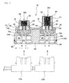
- Fig. 1 is a vertical cross sectional view of a gas generator for an air bag which is one embodiment of the present invention
- Fig. 2 is a vertical cross sectional view of an igniter in Fig. 1
- Fig. 3 is a cross sectional view for explaining an inner structure of the igniter.
- Fig. 1 shows a pyrotechnic type gas generator for an air bag in which only a gas generated by combustion of a gas generating agent inflates an air bag.
- a substantially cylindrically-shaped inner cylindrical member 104 is arranged in a housing 103 formed by joining a diffuser shell 101 having a gas discharging port and a closure shell 102 forming an inner accommodating space together with the diffuser shell, and the outside thereof is defined as a first combustion chamber 105a.
- a stepped notch portion is provided inside the inner cylindrical member 104, a disk-like partition wall 107 is disposed at the stepped notch portion, and the space in the inner cylindrical member 104 is partitioned into two chambers by the partition wall 107 so that a second combustion chamber 105b is defined in the diffuser shell side (the upper space) and an ignition means is stored in the closure shell side (the lower space).
- Gas generating agents 109a and 109b which are burnt by the ignition means activated due to the impact to generate a combustion gas, are stored in the first and second combustion chambers 105a and 105b, and the ignition means is provided with a first igniter 112a and a second igniter 112b which are activated due to the impact for ignition.
- the first igniter 112a and the second igniter 112b are activated by the activation-signal outputted on the basis of that a sensor detects the impact, and they are provided in parallel to an initiator collar 113 serving as a holder, having their head portions exposed. Then, the first igniter 112a and the second igniter 112b are fixed to the initiator collar 113 by a metallic pressing member 130 from the above.
- the first igniter 112a has a grounding pin 181 [the negative electrode (or the positive electrode)] and a center pin 182 [the positive electrode (or the negative electrode)] .
- a bridge wire 119 which is a conductive wire such as an electric resistance wire or the like at the portions thereof contacting with a priming as shown in Fig. 3, the other end of the grounding pin 181 is connected to a metal portion of a motor vehicle via a connector to ground, while the other end of the center pin 182 is connected to an external power supply via the connector.
- the grounding pin 181 is connected to a metallic eyelet 195, and the center pin 182 is insulated from the metallic eyelet 195 by a glass 196.
- a bridge wire (electric resistance wire) 119 is connected between the one end of the center pin 182 and the eyelet, and the bridge wire 119 contacts with a priming 197.
- the first igniter 112a has a structure such that the priming 197 and a charge holder 121 are disposed inside a metallic cover member 164, and the cover member 164 and the eyelet 195 contact with each other. Also, the cover member 164 can be covered with a thin film developing an electrical insulation.
- the second igniter 112b has a grounding pin 191 (the negative electrode) and a center pin 192 (the positive electrode).
- a bridge wire 119 which is a conductive wire such as an electric resistance wire or the like at the portions thereof contacting with a priming 197, and the other end of the grounding pin 191 is connected to a metal portion of the motor vehicle via a connector to ground, while the other end of the center pin 192 is connected to an external power supply via the connector.
- an opening/shutting means (a switch) of current (not shown) is provided between the center pin 192 and the external power supply.
- the grounding pin 191 is connected to a metallic eyelet 195, and the center pin 192 is insulated from the metallic eyelet 195 by a glass 196.
- a bridge wire (electric resistance wire) 119 is connected between the one end of the center pin 192 and the eyelet, and the bridge wire 119 contacts with a priming 197.
- the second igniter 112b has a structure such that the priming 197 and a charge holder 121 are disposed inside a metallic cover member 164, and the cover member 164 and the eyelet 195 contact with each other. Also, the cover member 164 can be covered with a thin film developing an electrical insulation.
- a transfer charge 116 accommodated in an aluminum cup is disposed above the first igniter 112a, and the transfer charge 116 is separated from the second combustion chamber 105b by a substantially cylindrical partition member 140 (shown in the drawing) and the partition wall 107.
- a flame-transferring hole 117 is provided in the inner cylindrical member 104, and the hole is closed by a seal tape 118.
- a through-hole 110 is provided in the inner cylindrical member 104 defining the first combustion chamber 105a and the second combustion chamber 105b, and the through-hole is closed by a seal tape 111.
- the seal tape 111 is ruptured when the gas generating agent is burnt, both the combustion chambers can communicate with each other through the through-hole 110.
- An opening area of the through-hole 110 is larger than that of the gas discharging port 126, and it does not have a function for controlling the internal pressure in the second combustion chamber 105b.
- a common coolant/filter 122 for purifying and cooling combustion gases generated by combustion of the first and second gas generating agents 109a and 109b is disposed in the housing 103, and an inner circumferential surface of the filter 122 in the diffuser shell 101 side is covered with a short-pass preventing member 123.
- an outer layer 124 for suppressing expansion of the filter 122 due to passing of the combustion gas or the like is disposed outside the coolant/filter 122.
- the outer layer 124 can be made of, for example, a laminated wire mesh body.
- a gap 125 is formed outside the outer layer 124 so that the combustion gas can pass through all portions of the filter 122.
- a gas discharging port 126 formed in the diffuser shell is closed by a seal tape 127 in order to block the outside air.
- the metallic pressing member 130 may be broken by a pressure of that combustion and the broken portion may make a bridge between the first igniter 112a and the second igniter 112b.
- (+) current can flow in the second igniter 112b via the pressing member 130, or the pressing member 130 and the partition member 140.
- (+) current flows in the second igniter 112b in this manner, the (+) current flows in only the grounding pin 191, and it never flows in the center pin 192.
- the opening/shutting means of current between the center pin 192 of the second igniter 112b and the external power supply is open so that current never flows in the center pin 192.
- (+) current flows from the center pin 192 to the grounding pin 181 of the first igniter 112a through the bridge wire 119 and the bridging broken portion.
- the priming 197 is ignited so that the second igniter 112b may be activated erroneously.
- the center pin 192 of the second igniter 112b is set to the positive electrode and the opening/shutting means of current is provided between the center pin 192 and the external power supply, an erroneous activity of the second igniter 112b can be prevented unfailingly.
- FIG. 4 is a vertical cross sectional view of a gas generator for an air bag according to other embodiment of the present invention
- Fig. 5 is a vertical cross sectional view of the initiator assembly in Fig. 4.
- Fig. 4 shows a pyrotechnic type gas generator for an air bag in which only a gas generated by combustion of a gas generating agent inflates an air bag.
- This gas generator is different in an ignition means from the gas generator for an air bag shown in Fig. 1, but is approximately identical to the same in the other portions, so that only the ignition means will be explained.
- the ignition means includes an initiator assembly 10 and a transfer charge 116 filled in an aluminum cup.
- the initiator assembly 10 is fitted into an inner cylindrical member 104 (in the space formed by the inner cylindrical member 104 and the partition wall 107), and it is mounted thereto by crimping a lower end portion 104a of the inner cylindrical member 104.
- the initiator assembly 10 includes a first igniter 32a, a second igniter 32b and a collar assembly 31.
- the collar assembly 31 includes a resin portion 36 made of a molding plastic material as a injection-molded insulating material and a metallic collar 40, and the base portions of the first igniter 32a and the second igniter 32b are surrounded by the resin portion 36.
- the metallic collar 40 is joined to the resin portion 36.
- an injection-molding process is employed for joining the collar assembly 31 comprising the resin portion 36 and the metallic collar 40 integrally with the first igniter 32a and the second igniter 32b.
- liquid-like or fluidized molding plastic material constituting the resin portion 36 is filled in between the base portions of the first igniter 32a and the second igniter 32b and the metallic collar 40.
- the metallic collar 40 is fixed on and retained to the resin portion 36, and the resin portion 36 is fixed on and retained to the first igniter 32a and the second igniter 32b.
- a groove 202 is formed around a lower end portion of the metallic collar 40 of the initiator assembly 10, and an O-ring made of rubber, plastic or the like is fitted in the groove 202. Then, by arranging the O-ring 200 in this manner, moisture is prevented from entering from the contacting portion between the inner cylindrical member 104 and the initiator assembly 10 (metallic collar 40), so that the interior of the gas generator for an air bag is kept in a moisture-proof state. Thus, since the interior is kept in the moisture-proof state, the performance of the gas generating agents 109a and 109b is prevented from deteriorating due to moisture absorption.
- the initiator assembly 10 includes the first initiator 32a and the second initiator 32b, but it is sufficient to provide only one O-ring 200, so that the number of manufacturing steps for the initiator assembly 10 is not increased as compared with that for a gas generator having a single initiator and moisture-proof of the former is substantially equal to that of the latter.
- the first igniter 32a and the second igniter 32b include a metallic eyelet (end plate) 46 in which a hole 50 is formed.
- the first igniter 32a has a center pin 54a [the positive electrode (or the negative electrode)] and a grounding pin 70a [the negative electrode (or the positive electrode)], while the second igniter 32b has a center pin 54b (the positive electrode) and a grounding pin 70b (the negative electrode) . Then, an unillustrated opening/shutting means of current is provided between the center pin 54b and an external power supply.
- bridge wires which are conductive wires such as electric resistance wires are disposed respectively between the center pins 54a and 54b and the eyelets 46, contacting with the priming 62.
- the bridge wires When current flows in the center pins 54a and 54b, the bridge wires generate heat to ignite the priming 62.
- the cover member 64 may be covered with a thin film developing an electrical insulation.
- center pins 54a and 54b go through holes 50, and the center pins 54a and 54b are positioned, insulated against the metallic eyelets 46 by glasses 33 corresponding to an electrical insulating body.
- the center pins 54a and 54b transmit ignition signals for igniting the priming 62.
- the cover member 64 comprising a metal wall encloses or covers the priming 62 filled in the charge holder 21 and it is welded to the eyelet 46. It is preferable that a circular end portion of the cover member 64 is provided with notches so that it can be broken easily and unfailingly. Such notches can be formed as grooves of about 0.10 to 0.25 mm radially, in case that the cover member 64 is made of stainless steel (SUS305).
- the grounding pins 70a and 70b are insulated from the center pins 54a and 54b by glasses 33.
- the resin portion 36 made of molding plastic material surrounds the metallic eyelets 46 of the first igniter 32a and the second igniter 32b, the center pins 54a, 54b and the grounding pins 70a, 70b, and in addition, the metallic collar 40 is mounted to the outside of the resin portion 36.
- the resin portion 36 is resin-molded integrally, including the metallic collar 40. At this time, the end surfaces of the center pins 54a and 54b, the eyelets 46, the glasses 33 holding the center pins 54a and 54b in the holes 50 of the eyelets 46 are put on the same plane.
- a front end peripheral surface of the resin portion 36 and a front end peripheral surface of the metallic collar 40 surrounding the resin portion 36 form a continuous circumferential surface to be frictionally fitted into the inner cylindrical member 104 shown in Fig. 4, and a projection 42 is formed on a front end peripheral surface of the resin portion 36.
- the projection 42 increase the friction between the inner cylindrical member 104 and the initiator assembly 10, prevents rattling or rotation of the initiator assembly 10, and facilitates a crimping process of the inner cylindrical member 104.
- the base portion of the resin portion 36 through which the center pins 54a, 54b and the grounding pins 70a, 70b pass insulates the metallic collar 40 from the center pins 54a, 54b and the grounding pins 70a, 70b.
- the metallic collar 40 has cavities 85 inside, and a surface of the cavity 85 is not covered with the molding plastic material and the metallic collar is exposed.
- the tip end portions of the center pins 54a, 54b and the grounding pins 70a, 70b protrude in the cavities 85 but the tip end portions are not exposed out of the cavities 85 of the metallic collars 40. This is for preventing the pins from being deformed during assembling the initiator.
- Connectors 23a and 23b shown with a chain line in the drawing are fitted into and connected to the cavities 85. That is, the inside of the cavity 85 serves as a connecting portion in which the connector is fitted.
- a recessed notch 88 is provided inside the end portion of the connector connecting cavity 85 of the metallic collar 40 in the circumferential direction, thereby forming a falling-out preventing means for the fitted connector.
- the current flows through the grounding pin 70a via the bridge wire 19, the priming 62 is ignited and burnt in the course, and then the transfer charge 116 is ignited and burnt. Consequently, the seal tape 118 is ruptured by a high temperature gas generated by combustion of the transfer charge 116, the high temperature gas enters the first combustion chamber 105a through the flame-transferring holes 117, and the first gas generating agent 109a is ignited and burnt to generate a gas.
- the metallic pressing member 130 may be broken by a pressure of that combustion and the broken portion may make a bridge between the first igniter 112a and the second igniter 112b.
- (+) current can flow in the second igniter 112b via the pressing member 130, or the pressing member 130 and the partition member 140.
- (+) current flows in the second igniter 32b in this manner, the (+) current flows in only the grounding pin 70b, and it never flows in the center pin 54b.
- the opening/shutting means of current between the center pin 54b of the second igniter 32b and the external power supply is open so that current is prevented from flowing in the center pin 54b.
- (+) current flows from the center pin 54b to the grounding pin 54b of the first igniter 32a through the bridge wire 19 and the bridging broken portion.
- the priming 62 is ignited so that the second igniter 32b may be activated erroneously.
- the center pin 54b of the second igniter 32b is set to the positive electrode and the opening/shutting means of current is provided between the center pin 54b and the external power supply, an erroneous activity of the second igniter 112b can be prevented unfailingly.
- the air bag system according to the present invention can use the pyrotechnic type gas generators shown in Fig. 1 and Fig. 4. Naturally, any gas generator according to the present invention can be used regardless of whether the gas generator is pyrotechnic or not.
- the air bag system is provided with an activation-signal outputting means comprising an impact sensor and a control unit, and a module case in which the gas generator and an air bag are accommodated.
- the gas generator is connected to the activation-signal outputting means (the impact sensor and the control unit) in the side where the first igniter 117 and the second igniter 140 are provided.
- an inflating speed of the air bag can be adjusted in accordance to a degree of the impact by activating only the first igniter 117, or activating the first igniter 117 and the second igniter 140 at different timings, or activating two igniters.
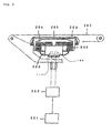
- FIG. 6 shows one embodiment of the air bag system of the present invention.
- the air bag system comprises a gas generator 200, an impact sensor 201, a control unit 202, a module case 203 and an air bag 204.
- the gas generator 200 the gas generator described with reference to Fig. 1 is used, and the activating performance thereof is adjusted to give as little an impact as possible to an at the initial stage in the activation of the gas generator.
- the impact sensor 201 can comprise, for example, a semiconductor type acceleration sensor.
- a semiconductor type acceleration sensor In this semiconductor type acceleration sensor, four semiconductor strain gauges are formed on a beam of a silicon substrate to be bent when acceleration is applied, and these semiconductor strain gauges are bridge-connected. When an acceleration is applied, the beam defects and a strain is produced the surface. The resistances of the semiconductor strain gauges are changed due to this strain, the resistance change is detected as a voltage signal proportional to the acceleration.
- the control unit 202 is provided with an ignition-judgement circuit, and a signal from the semiconductor type acceleration sensor is inputted to the ignition-judgement circuit.
- the control unit 202 starts calculation at a time when the impact signal from the sensor 201 exceeds a predetermined value and, when the calculated result exceeds a predetermined value, a activation-signal is outputted to the igniter of the gas generator 200, namely, the first igniter 117 or the second igniter 140.
- the module case 203 is made of, for example, polyurethane and it includes a module cover 205.
- the air bag 204 and the gas generator 200 are accommodated in the module case 203 to be constituted as a pad module.
- the pad module is ordinarily mounted to a steering wheel 207 when it is mounted in a driver side in an automobile.
- the air bag 204 is made of nylon (for example, nylon 66), polyester or the like, the opening 206 thereof surrounds a gas discharging port of the gas generator, and the air bag is fixed to a flange portion of the gas generator in a folded state.
- the detection signal is transmitted to the control unit 202, and when the impact signal from the sensor exceeds the predetermined value, the control unit 202 starts calculation.
- a working signal is output to the first igniter 117 or the second igniter 140 of the gas generator 200.
- the igniter is activated to ignite the gas generating agent so that the gas generating agent is burnt to generate gas.
- This gas is injected to the air bag 204 and thereby the air bag breaks the module cover 205 to inflate so that a cushion absorbing the impact is formed between the steering wheel 207 and the occupant.
Abstract
Description
- The present invention relates to a gas generator for an air bag and an air bag system using the same.
- As a gas generator for an air bag, there are a pyrotechnic-type gas generator in which only a gas generated by combustion of a gas generating agent is used for inflating an air bag and a hybrid-type gas generator in which a gas generated by combustion of a gas generating agent and a pressurized medium are used for inflating the air bag. Then, in the gas generator for the air bag used therefor, an ignition means provided with an igniter is employed as a means for generating a gas, and a single-type gas generator with one igniter and a dual-type gas generator with two igniters are used at present.
- In the case of a dual-type gas generator with two igniters, two conductive pins (a center pin and a grounding pin) of the positive electrode and the negative electrode are provided in the respective igniters. By electrifying the respective conductive pins, a priming is ignited and burnt at conductive wires (namely, heat generating wires, electric resistance wires or the like), which connect the two conductive pins, in the course of current flows from the positive electrodes to the negative electrodes and the gas generating agents are burnt, in some cases, through ignition and burning of transfer charges.
- As such a dual type gas generator for the air bag, there is one which is adjusted to activate only one igniter or to activate both igniters according to the magnitude of the impact on the vehicle. In this case, it is important that the other igniter is not activated erroneously when the magnitude of impact is rather small and only one igniter is actuated.
- An object of the present invention is to provide a gas generator for an air bag in which an erroneous activation of a second igniter due to an actuation of a first igniter can be prevented and reliability as an article is enhanced, and an air bag system using the same.
- As a solving means, the present invention provides a gas generator for an air bag which comprises, in a housing having a gas discharging port, an ignition means provided with first and second igniters including a priming activated by the impact, and a gas generating means ignited and burnt by the ignition means to generate a combustion gas, wherein
the first and second igniters are mounted to the housing via a holder; and
in the second igniter, a center pin is connected to an external power supply to constitute the positive electrode, a grounding pin is connected to a metal portion of a motor vehicle to constitute the negative electrode, and an opening/shutting means of current is provided between the center pin and the external power supply. - The second igniter constituting the ignition means can be adjusted to be activated simultaneously with the first igniter or to be activated after the first igniter is activated.
- In this invention, the grounding pin and the center pin are connected to each other by a conductive wire (that is, a heat generating wire, an electric resistance wire or the like) at positions where one end portions thereof contact with priming, and the priming is ignited and burnt by electrifying the conductive wire. Furthermore, the grounding pin is a conductive pin whose portion contacts with a conductive body (for example, a metallic eyelet), and the center pin is a conductive pin which is insulated from the conductive wire by glass or the like.
Incidentally, the conductive pin serving as the negative electrode is connected to a metal portion of a vehicle to ground. For example, it is also considered a case such that the grounding pin is provided to electrically connect to a metal portion constituting an outer shell vessel of the igniter and the center pin is provided to electrically connect to the grounding pin only via an electric resistance wire. Here, in the present description, the electrical connection means direct connection or indirect connection via another conductive member in a state of being electrified. - In the gas generator for an air bag of the present invention, the center pin of the second igniter is set to the positive electrode (that is, the grounding pin is set to the negative electrode). Accordingly, when (+) current flows from the first igniter to the conductive member (the metallic eyelet), the (+) current flows to the grounding pin of the negative electrode to be discharged due to grounding, and thereby the second igniter can never be activated erroneously.
- Further, the gas generator for an air bag of the present invention is provided with an opening/shutting means of current between the center pin of the second igniter and the external power supply. In case that only the first igniter is activated, the opening/shutting means is open and current does not flow into the center pin, so that current is prevented from flowing from the center pin of the second igniter to the negative electrode of the first igniter via the conductive wire (that is, a heat generating wire, an electric resistance wire or the like) . Accordingly, the second igniter can never be activated erroneously.
- Since the gas generator for an air bag of the present invention is characterized by arrangement of the positive electrode and the negative electrode of the conductive pins in the two igniters, and the opening/shutting means of current, the present invention is not particularly limited to the structure of the gas generator for an air bag itself, but, for example, the ignition means can be constituted as the following initiator assembly.
- In the present invention, the ignition means provided with the first and second igniters including a priming activated due to the impact is an ignition means including an initiator assembly activated by the impact and a transfer charge,
the initiator assembly includes the first and second igniters, which are used for igniting priming and includes at least one conductive pin respectively, and a collar assembly retaining the initiator assembly to the gas generator; and
preferably, the collar assembly has an insulating material surrounding at least a portion of the first and second igniters and a collar joined to the insulating material. - Incidentally, the collar forming the collar assembly, that is, a holder, may be any member having a function serving as a collar (a space retaining function) , and preferably it is made of ceramics or metal, more preferably, it is made of metal.
- Further, preferably, in the initiator assembly, at least one conductive pin, a metallic eyelet of an igniter having a hole through which the conductive pin passes, and an electrically insulating body filled in the hole to insulate the conductive pin from the eyelet are provided so that the end faces thereof exist on the same plane.
- Next, a preferable initiator assembly used in the gas generator for an air bag of the present invention will be explained.
- When the initiator assembly is activated by an ignition signal received by the conductive pin of the initiator, it ignites and burns the priming disposed in the vicinity of the conductive pin. The initiator assembly includes the first and second igniters, and the collar assembly joined thereto. In addition to the at least one conductive pin, the first and second igniters each have a charge holder formed by using a cap member (cover member) comprising a metallic wall or a resin surrounding the priming ignited when an ignition signal is received. The collar member retains the initiator assembly to the housing of the inflator even after the initiator assembly is activated.
- The collar assembly includes an injection-molded insulating material and a collar, and the collar is fixed and joined to the insulating material made of an injection-molding plastic material during an injection-molding process.
- The insulating material is useful for insulating one conductive pin from the second conductive pin, or in another embodiment, it is useful for insulating one conductive pin from another conductive component in a different electric potential therefrom when the one conductive pin receives an ignition signal.
- The collar is a single integral piece which can be defined to include a body portion and a shoulder portion. The body portion is arranged so that a front end annular cylindrical portion thereof is fitted and fixed on the outer periphery of the insulating material made of a molding plastic material injection-molded to surround conductive pins, generally two conductive pins comprising the center pin and the grounding pin. And the conductive pins extend inside a cylindrical portion extending rearward. Then, the inner space of the rearward cylindrical body receives a connector connected to the conductive pins. In this collar, it is preferable that inner circumferential surface of the cylindrical body portion extending rearward (that is, a rear half) is formed not to be covered with an insulating material (that is, injection-molded resin or the like), exposing the collar. This is for securely eliminating a possibility such that a connector disposed in the inner space of the cylindrical portion drops off due to, for example, the impact of activation of the first and second igniters.
- The shoulder portion is expanded outwardly in the radial direction from the rearward cylindrical portion of the body portion to be contact-engaged with an engaging portion of the housing of the inflator. The mutual engagement between the shoulder portion and the engaging portion of the inflator housing controls the relative positioning of the initiator assembly to the inflator housing before and after activation of the initiator assembly. The outward position of the shoulder portion defines the length or the dimension of the outside of the collar.
- In the initiator assembly of this invention, a priming is stored in a charge holder made of a cover member comprising a cylindrical metallic wall, a resin or the like mounted to a metallic eyelet (end plate), the metallic eyelet has a cylindrical shape with a hole, and the hole formed in a center of the eyelet is filled with an electrical insulator (comprising glass).
- The center pin of the electrode goes through the insulating material in the collar, then goes through a electrical insulating body in the eyelet, and the front end thereof contacts with the priming. Also, the upper surface of the eyelet also contacts with the priming, and the front end of the second conductive pin, namely the grounding pin of the electrode is connected to the lower surface of the eyelet in a state of being able to be electrified. As the priming stored in the cover member or the charge holder, a material of zirconium-potassium perchlorate can be used. A means for igniting the priming on the basis of an ignition signal is provided between the center pin described above and the eyelet. That is, the means comprises a resistance wire connected between the both. The initiator assembly used in the present invention has the following features.
- (1) The end surfaces of the center pin, the eyelet, and the electrical insulating material are on the same plane, and they are integrally fixed by molding a resin together with the collar, thereby forming a pin-type. The pin-type is an igniter in which the conductive pins project in the collar assembly, particularly, in the inner space of the rearward cylindrical body of the body portion in the collar, and the conductive pins and lead wires are connected by receiving and engaging the connector at the front ends of lead wires in the inner space of the rearward cylindrical body in the body portion, and thereby the both are made conductive. Such a pin-type aims to downsize the initiator and make the initiator handy by attaching the connector and the lead wires separately afterwards. In such a pin-type, by positioning the end surfaces of the center pin, the eyelet and the insulating body on the same plane, the initiator assembly which is easily manufactured and in that a manufacturing cost is not increased is realized. That is, the igniter activated by an electric signal needs to have a structure for igniting and burning the priming by an electrical activation signal, and an electric resistance body (resistance wires in the present specification) for converting electric energy (that is, an electric signal) to heat energy is used as such a structure. The resistance wires are provided to connect one conductive pin and another conductive component (for example, another conductive pin or an eyelet) having a different electrical potential therefrom when the one conductive pin receives the ignition signal, and preferably at this time, the resistance wire is provided straight without sagging between the conductive pin and the conductive component. If the end surfaces of the center pin, the eyelet and the insulating body are on the same plane, by pulling and welding the resistance wires to the conductive pin and the conductive component, the resistance wires can be arranged to abut on the flat end surfaces of the center pin, the eyelet and the insulating body without sagging. That is, the resistance wires can be connected to the conductive pin and the conductive component easily and securely.
- (2) As the insulating material surrounding a portion of the initiator, a plastic material which can be injection-molded is used, and as such a resin, nylon 6/12 resin, polybutylene terephthalate (PBT) resin, or polyacetal resin is used. By using these resins, the insulating resistance is increased as compared with nylon 6 resin which has been used conventionally, so that insulation between the conductive pins and between the conductive pins and the collar can be obtained securely.
- (3) In order to increase friction between the inner cylindrical member of the inflator and the initiator assembly and prevent rattling or rotation of the initiator assembly so that a crimping process of the inner cylindrical member is facilitated, a projection is formed on the outer periphery of the insulating material (molded resin portion) surrounding the metallic eyelet (end plate). It is preferable that the projection is formed in one of various cone shapes such as a circular cone, a pyramid or the like, but even another shape can be employed as long as it can be fitted in between the inner cylindrical member and the initiator assembly to increase the frictional resistance therebetween. Also, the projection is formed to have a size slightly larger than a gap obtained between the inner cylindrical member and the initiator assembly, and it is formed to be collapsed or flexed and press-fitted between the initiator assembly and the inner cylindrical member, when the initiator assembly is joined to one end of the inner cylindrical member. In order to secure such a function, for example, when the width of the gap is 0.75mm, the function can be realized by forming the projection in a size larger than the gap by 0.1 to 0.2mm or so.
- (4) The center pin and the grounding pin in the connecting space with the connector in the collar are arranged such that they do not project out of the collar in order to prevent the pins from deforming during assembling the initiator assembly.
- (5) A connector dropping-out preventing means is provided in the connecting space with the connector in the collar. For this, it is sufficient to provide a recessed notch inside the collar.
- (6) In order to coincide the conductive pins (the grounding pin and the center pin) and the connector with each other regarding positive and negative electrodes, a D feature type or T feature type projection is provided in the connecting space. More particularly, a projection or recess in a D-letter or T-letter shape is formed on the insulating material (molded resin) exposing to the bottom surface of the connector connecting space.
- (7) The inside of the collar is not covered with the injection-molded insulating material (molding plastic material), and the connector is fitted to contact directly with the metal surface of the inside of the collar. Thereby, the connector can be prevented from falling out due to the reaction of activation of the igniter.
- (8) A mounting means for a connector having lead wires is provided to decide the direction of the lead wires with respect to the gas generator. Specifically, recesses or projections extending in the axial direction are provided on an edge portion of the collar in asymmetrical manner.
-
- The gas generator for an air bag of the present invention may have a structure such that an air bag is inflated by only a combustion gas generated by combustion of the gas generating means.
- Also, the present invention provides an air bag system including a gas generator for an air bag, an impact sensor for detecting the impact to activate the gas generator, an air bag introducing therein a gas generated in the gas generator and/or a pressurized medium to inflate, wherein the gas generator for an air bag is the gas generator for an air bag described above.
- Particularly, the air bag system in the present invention can be provided with the following structure.
- That is, an air bag system is an air bag apparatus comprising a gas generator for a air bag accommodating an ignition means in a housing having a gas discharging port and an activation-signal outputting device for outputting an electrical-activation signal to the gas generator, wherein the ignition means is provided with a first igniter and a second igniter activated by the electrical activation-signal and the first and second igniters are mounted to the housing via a holder, the igniter comprises a grounding pin which electrically connects to a metal portion of an outer shell in the igniter and a center pin which electrically connects to the grounding pin via only an electric resistance wire, and the activation-signal outputting device is provided with an opening/shutting means controlling the output of the activation-signal to each igniter, and in the second igniter, the center pin is connected to a activation-signal outputting means to serve as the positive electrode.
- The activation-signal outputting means described above is a device which can output an electrical activation-signal to at least the igniter, and one provided as a control unit conventionally or one provided by being combined with the control unit and an impact sensor or the like can be used as this means.
- The present invention also provides a method of receiving an activation-signal in a gas generator for an air bag activated by receiving an electrical activation-signal.
- That is, in the method of receiving an activation-signal, a gas generator comprises an ignition means in a housing having a gas discharging port, the ignition means is provided with a first igniter and a second igniter activated by an electrical activation-signal, the first and second igniters are mounted to the housing via a holder, and the igniter comprises a grounding pin which electrically connects to a metal portion of an outer shell of the igniter and a center pin which electrically connects to the grounding pin via only an electric resistance wire, and in the second igniter, the center pin serves as the positive electrode to receive the electric activation-signal.
- In the gas generator for an air bag of the present invention, there is no possibility such that the second igniter may be activated erroneously by activation of the first igniter.
-
- Fig. 1 is a vertical cross sectional view of a gas generator for an air bag of one embodiment of the present invention.
- Fig. 2 is a vertical cross sectional view of an ignition means in Fig. 1.
- Fig. 3 is a cross sectional view for explaining the structure of the ignition means.
- Fig. 4 is a vertical cross sectional view of a gas generator for an air bag of another embodiment of the present invention.
- Fig. 5 is a cross sectional view of an ignition means in Fig. 4.
- Fig. 6 is a schematic view showing one embodiment of an air bag system of the present invention.
-
-
- 10
- initiator assembly
- 32a
- first igniter
- 32b
- second igniter
- 54a, 54b
- center pins
- 70a, 70b
- grounding pins
- 112a
- first igniter
- 112b
- second igniter
- 113
- initiator collar
- 181, 191
- grounding pins
- 182, 192
- center pins
- 130
- pressing member
- 217
- first igniter
- 240
- second igniter
- 217a, 240a
- center pins
- 217b, 240b
- grounding pins
- First of all, one embodiment of a gas generator for an air bag of the present invention will be explained with reference to Fig. 1 to Fig. 3. Fig. 1 is a vertical cross sectional view of a gas generator for an air bag which is one embodiment of the present invention, Fig. 2 is a vertical cross sectional view of an igniter in Fig. 1, and Fig. 3 is a cross sectional view for explaining an inner structure of the igniter. Fig. 1 shows a pyrotechnic type gas generator for an air bag in which only a gas generated by combustion of a gas generating agent inflates an air bag.
- In the gas generator shown in Fig.1, a substantially cylindrically-shaped inner
cylindrical member 104 is arranged in ahousing 103 formed by joining adiffuser shell 101 having a gas discharging port and aclosure shell 102 forming an inner accommodating space together with the diffuser shell, and the outside thereof is defined as afirst combustion chamber 105a. - A stepped notch portion is provided inside the inner
cylindrical member 104, a disk-like partition wall 107 is disposed at the stepped notch portion, and the space in the innercylindrical member 104 is partitioned into two chambers by thepartition wall 107 so that asecond combustion chamber 105b is defined in the diffuser shell side (the upper space) and an ignition means is stored in the closure shell side (the lower space). -
Gas generating agents second combustion chambers first igniter 112a and asecond igniter 112b which are activated due to the impact for ignition. - The
first igniter 112a and thesecond igniter 112b are activated by the activation-signal outputted on the basis of that a sensor detects the impact, and they are provided in parallel to aninitiator collar 113 serving as a holder, having their head portions exposed. Then, thefirst igniter 112a and thesecond igniter 112b are fixed to theinitiator collar 113 by a metallic pressingmember 130 from the above. - As shown in Fig. 2, the
first igniter 112a has a grounding pin 181 [the negative electrode (or the positive electrode)] and a center pin 182 [the positive electrode (or the negative electrode)] . One ends of thegrounding pin 181 and thecenter pin 182 are connected to each other by abridge wire 119 which is a conductive wire such as an electric resistance wire or the like at the portions thereof contacting with a priming as shown in Fig. 3, the other end of thegrounding pin 181 is connected to a metal portion of a motor vehicle via a connector to ground, while the other end of thecenter pin 182 is connected to an external power supply via the connector. Furthermore, a part of thegrounding pin 181 is connected to ametallic eyelet 195, and thecenter pin 182 is insulated from themetallic eyelet 195 by aglass 196. A bridge wire (electric resistance wire) 119 is connected between the one end of thecenter pin 182 and the eyelet, and thebridge wire 119 contacts with apriming 197. Thereby, when thecenter pin 182 is electrified, current flows through thebridge wire 119 so that thepriming 197 is ignited. Further, thefirst igniter 112a has a structure such that thepriming 197 and acharge holder 121 are disposed inside ametallic cover member 164, and thecover member 164 and theeyelet 195 contact with each other. Also, thecover member 164 can be covered with a thin film developing an electrical insulation. - The
second igniter 112b has a grounding pin 191 (the negative electrode) and a center pin 192 (the positive electrode). One ends of thegrounding pin 191 and thecenter pin 192 are connected to each other by abridge wire 119 which is a conductive wire such as an electric resistance wire or the like at the portions thereof contacting with apriming 197, and the other end of thegrounding pin 191 is connected to a metal portion of the motor vehicle via a connector to ground, while the other end of thecenter pin 192 is connected to an external power supply via the connector. Then, an opening/shutting means (a switch) of current (not shown) is provided between thecenter pin 192 and the external power supply. Furthermore, a part of thegrounding pin 191 is connected to ametallic eyelet 195, and thecenter pin 192 is insulated from themetallic eyelet 195 by aglass 196. A bridge wire (electric resistance wire) 119 is connected between the one end of thecenter pin 192 and the eyelet, and thebridge wire 119 contacts with apriming 197. Thereby, when thecenter pin 192 is electrified, current flows through thebridge wire 119 so that thepriming 197 is ignited. Further, thesecond igniter 112b has a structure such that thepriming 197 and acharge holder 121 are disposed inside ametallic cover member 164, and thecover member 164 and theeyelet 195 contact with each other. Also, thecover member 164 can be covered with a thin film developing an electrical insulation. - A
transfer charge 116 accommodated in an aluminum cup is disposed above thefirst igniter 112a, and thetransfer charge 116 is separated from thesecond combustion chamber 105b by a substantially cylindrical partition member 140 (shown in the drawing) and thepartition wall 107. A flame-transferringhole 117 is provided in the innercylindrical member 104, and the hole is closed by aseal tape 118. - A through-
hole 110 is provided in the innercylindrical member 104 defining thefirst combustion chamber 105a and thesecond combustion chamber 105b, and the through-hole is closed by aseal tape 111. Incidentally, since theseal tape 111 is ruptured when the gas generating agent is burnt, both the combustion chambers can communicate with each other through the through-hole 110. An opening area of the through-hole 110 is larger than that of thegas discharging port 126, and it does not have a function for controlling the internal pressure in thesecond combustion chamber 105b. - A common coolant/
filter 122 for purifying and cooling combustion gases generated by combustion of the first and secondgas generating agents housing 103, and an inner circumferential surface of thefilter 122 in thediffuser shell 101 side is covered with a short-pass preventing member 123. - Outside the coolant/
filter 122, anouter layer 124 for suppressing expansion of thefilter 122 due to passing of the combustion gas or the like is disposed. Theouter layer 124 can be made of, for example, a laminated wire mesh body. - A
gap 125 is formed outside theouter layer 124 so that the combustion gas can pass through all portions of thefilter 122. Agas discharging port 126 formed in the diffuser shell is closed by aseal tape 127 in order to block the outside air. - When the
center pin 182 of thefirst igniter 112a is electrified, current flows into thegrounding pin 181 via thebridge wire 119, thepriming 197 is ignited and burnt in the course, and then thetransfer charge 116 is ignited and burnt. Then, theseal tape 118 is ruptured by a high-temperature gas generated by combustion of thetransfer charge 116. The high temperature gas flows through the flame-transferringhole 117 into thefirst combustion chamber 105a to ignite the firstgas generating agent 109a, and thereby a gas is generated. - In this case, when the
priming 197 is ignited and burnt by activation of thefirst igniter 112a, the metallic pressingmember 130 may be broken by a pressure of that combustion and the broken portion may make a bridge between thefirst igniter 112a and thesecond igniter 112b. In such a situation, (+) current can flow in thesecond igniter 112b via the pressingmember 130, or thepressing member 130 and thepartition member 140. - Also, in a case that the
metallic cover member 164 accommodating thepriming 197 in thefirst igniter 112a contacts with thepressing member 130 to be electrified due to activation of thefirst igniter 112a, broken portions of thecover member 164 and thepressing member 130 may make a bridge between thefirst igniter 112a and thesecond igniter 112b. In such a situation, (+) current of thefirst igniter 112a can flow into thesecond igniter 112b via the pressingmember 130, or thepressing member 130 and thepartition member 140. At this time, even when an outer surface of thecover member 164 in the both igniters is covered with a film having an insulation (hereinafter, referred to as an insulating film), the same problem occurs when the film is broken. - Then, regarding the possibility that (+) current of the
first igniter 112a flows into thesecond igniter 112b, even if the center pin in thefirst igniter 112a is set to (+) pole, a similar problem will occur when a tip end portion of the bridge wire connecting to thecenter pin 182 contacts with a conductive portion such as thecover member 164 or the like, for any reason, after activation of thefirst igniter 112a. - However, in the case that (+) current flows in the
second igniter 112b in this manner, the (+) current flows in only thegrounding pin 191, and it never flows in thecenter pin 192. - Furthermore, when only the
first igniter 112a is activated, the opening/shutting means of current between thecenter pin 192 of thesecond igniter 112b and the external power supply is open so that current never flows in thecenter pin 192. In a case that the opening/shutting means is shut or there is no opening/shutting means, (+) current flows from thecenter pin 192 to thegrounding pin 181 of thefirst igniter 112a through thebridge wire 119 and the bridging broken portion. In that course, thepriming 197 is ignited so that thesecond igniter 112b may be activated erroneously. - As mentioned above, in the present invention, since the
center pin 192 of thesecond igniter 112b is set to the positive electrode and the opening/shutting means of current is provided between thecenter pin 192 and the external power supply, an erroneous activity of thesecond igniter 112b can be prevented unfailingly. - Next, other embodiment of the gas generator for an air bag of the present invention will be explained with reference to Fig. 4 and Fig. 5. Fig. 4 is a vertical cross sectional view of a gas generator for an air bag according to other embodiment of the present invention, and Fig. 5 is a vertical cross sectional view of the initiator assembly in Fig. 4. Fig. 4 shows a pyrotechnic type gas generator for an air bag in which only a gas generated by combustion of a gas generating agent inflates an air bag. This gas generator is different in an ignition means from the gas generator for an air bag shown in Fig. 1, but is approximately identical to the same in the other portions, so that only the ignition means will be explained.
- The ignition means includes an
initiator assembly 10 and atransfer charge 116 filled in an aluminum cup. Theinitiator assembly 10 is fitted into an inner cylindrical member 104 (in the space formed by the innercylindrical member 104 and the partition wall 107), and it is mounted thereto by crimping alower end portion 104a of the innercylindrical member 104. - The
initiator assembly 10 includes afirst igniter 32a, asecond igniter 32b and a collar assembly 31. - The collar assembly 31 includes a
resin portion 36 made of a molding plastic material as a injection-molded insulating material and ametallic collar 40, and the base portions of thefirst igniter 32a and thesecond igniter 32b are surrounded by theresin portion 36. - The
metallic collar 40 is joined to theresin portion 36. For joining the collar assembly 31 comprising theresin portion 36 and themetallic collar 40 integrally with thefirst igniter 32a and thesecond igniter 32b, an injection-molding process is employed. In this case, liquid-like or fluidized molding plastic material constituting theresin portion 36 is filled in between the base portions of thefirst igniter 32a and thesecond igniter 32b and themetallic collar 40. When the plastic material is solidified, themetallic collar 40 is fixed on and retained to theresin portion 36, and theresin portion 36 is fixed on and retained to thefirst igniter 32a and thesecond igniter 32b. - A
groove 202 is formed around a lower end portion of themetallic collar 40 of theinitiator assembly 10, and an O-ring made of rubber, plastic or the like is fitted in thegroove 202. Then, by arranging the O-ring 200 in this manner, moisture is prevented from entering from the contacting portion between the innercylindrical member 104 and the initiator assembly 10 (metallic collar 40), so that the interior of the gas generator for an air bag is kept in a moisture-proof state. Thus, since the interior is kept in the moisture-proof state, the performance of thegas generating agents initiator assembly 10 includes thefirst initiator 32a and thesecond initiator 32b, but it is sufficient to provide only one O-ring 200, so that the number of manufacturing steps for theinitiator assembly 10 is not increased as compared with that for a gas generator having a single initiator and moisture-proof of the former is substantially equal to that of the latter. - The
first igniter 32a and thesecond igniter 32b include a metallic eyelet (end plate) 46 in which ahole 50 is formed. Thefirst igniter 32a has acenter pin 54a [the positive electrode (or the negative electrode)] and agrounding pin 70a [the negative electrode (or the positive electrode)], while thesecond igniter 32b has acenter pin 54b (the positive electrode) and agrounding pin 70b (the negative electrode) . Then, an unillustrated opening/shutting means of current is provided between thecenter pin 54b and an external power supply. Then, in the both igniters, bridge wires which are conductive wires such as electric resistance wires are disposed respectively between the center pins 54a and 54b and theeyelets 46, contacting with thepriming 62. When current flows in the center pins 54a and 54b, the bridge wires generate heat to ignite thepriming 62. Also, thecover member 64 may be covered with a thin film developing an electrical insulation. - The upper portions of the center pins 54a and 54b go through
holes 50, and the center pins 54a and 54b are positioned, insulated against themetallic eyelets 46 byglasses 33 corresponding to an electrical insulating body. - The center pins 54a and 54b transmit ignition signals for igniting the
priming 62. Thecover member 64 comprising a metal wall encloses or covers thepriming 62 filled in thecharge holder 21 and it is welded to theeyelet 46. It is preferable that a circular end portion of thecover member 64 is provided with notches so that it can be broken easily and unfailingly. Such notches can be formed as grooves of about 0.10 to 0.25 mm radially, in case that thecover member 64 is made of stainless steel (SUS305). - The grounding pins 70a and 70b are insulated from the center pins 54a and 54b by
glasses 33. - The
resin portion 36 made of molding plastic material surrounds themetallic eyelets 46 of thefirst igniter 32a and thesecond igniter 32b, the center pins 54a, 54b and the grounding pins 70a, 70b, and in addition, themetallic collar 40 is mounted to the outside of theresin portion 36. - The
resin portion 36 is resin-molded integrally, including themetallic collar 40. At this time, the end surfaces of the center pins 54a and 54b, theeyelets 46, theglasses 33 holding the center pins 54a and 54b in theholes 50 of theeyelets 46 are put on the same plane. - Also, a front end peripheral surface of the
resin portion 36 and a front end peripheral surface of themetallic collar 40 surrounding theresin portion 36 form a continuous circumferential surface to be frictionally fitted into the innercylindrical member 104 shown in Fig. 4, and aprojection 42 is formed on a front end peripheral surface of theresin portion 36. Theprojection 42 increase the friction between the innercylindrical member 104 and theinitiator assembly 10, prevents rattling or rotation of theinitiator assembly 10, and facilitates a crimping process of the innercylindrical member 104. - The base portion of the
resin portion 36 through which the center pins 54a, 54b and the grounding pins 70a, 70b pass insulates themetallic collar 40 from the center pins 54a, 54b and the grounding pins 70a, 70b. Themetallic collar 40 hascavities 85 inside, and a surface of thecavity 85 is not covered with the molding plastic material and the metallic collar is exposed. - The tip end portions of the center pins 54a, 54b and the grounding pins 70a, 70b protrude in the
cavities 85 but the tip end portions are not exposed out of thecavities 85 of themetallic collars 40. This is for preventing the pins from being deformed during assembling the initiator.Connectors cavities 85. That is, the inside of thecavity 85 serves as a connecting portion in which the connector is fitted. A recessednotch 88 is provided inside the end portion of theconnector connecting cavity 85 of themetallic collar 40 in the circumferential direction, thereby forming a falling-out preventing means for the fitted connector. - When the center pin 54 of the
first igniter 32a in theinitiator assembly 10 is electrified, the current flows through thegrounding pin 70a via thebridge wire 19, thepriming 62 is ignited and burnt in the course, and then thetransfer charge 116 is ignited and burnt. Consequently, theseal tape 118 is ruptured by a high temperature gas generated by combustion of thetransfer charge 116, the high temperature gas enters thefirst combustion chamber 105a through the flame-transferringholes 117, and the firstgas generating agent 109a is ignited and burnt to generate a gas. - In this case, when the
priming 62 is ignited and burnt due to activation of thefirst igniter 32a, the metallic pressingmember 130 may be broken by a pressure of that combustion and the broken portion may make a bridge between thefirst igniter 112a and thesecond igniter 112b. In such a situation, (+) current can flow in thesecond igniter 112b via the pressingmember 130, or thepressing member 130 and thepartition member 140. - Also, in a case that the
metallic cover member 64 accommodating thepriming 62 in thefirst igniter 32a contacts with thepressing member 130 to be electrified due to activation of thefirst igniter 32a, broken portions of thecover member 64 and thepressing member 130 may make a bridge between thefirst igniter 32a and thesecond igniter 32b. In such a situation, (+) current of thefirst igniter 32a can flow in thesecond igniter 32b via the pressingmember 130 or the like. At this time, even when an outer surface of thecover member 64 in the both igniters is covered with a film having an insulation (hereinafter, referred to as an insulating film), the same problem occurs when the film is broken. - Then, regarding the possibility such that (+) current of the
first igniter 32a flows in thesecond igniter 32b, even if the center pin in thefirst igniter 32a is set to (+) pole, a similar problem will occur when a tip end portion of the bridge wire connecting to thecenter pin 54a contacts with a conductive portion such as thecover member 64 or the like, for any reason, after activation of thefirst igniter 32a. - However, according to the present invention, if (+) current flows in the
second igniter 32b in this manner, the (+) current flows in only thegrounding pin 70b, and it never flows in thecenter pin 54b. - Furthermore, when only the
first igniter 32a is activated, the opening/shutting means of current between thecenter pin 54b of thesecond igniter 32b and the external power supply is open so that current is prevented from flowing in thecenter pin 54b. In a case that the opening/shutting means is shut or there is no opening/shutting means, (+) current flows from thecenter pin 54b to thegrounding pin 54b of thefirst igniter 32a through thebridge wire 19 and the bridging broken portion. In that course, thepriming 62 is ignited so that thesecond igniter 32b may be activated erroneously. - As mentioned above, in the present invention, since the
center pin 54b of thesecond igniter 32b is set to the positive electrode and the opening/shutting means of current is provided between thecenter pin 54b and the external power supply, an erroneous activity of thesecond igniter 112b can be prevented unfailingly. - The air bag system according to the present invention can use the pyrotechnic type gas generators shown in Fig. 1 and Fig. 4. Naturally, any gas generator according to the present invention can be used regardless of whether the gas generator is pyrotechnic or not. For example, when the gas generator for an air bag shown in Fig. 1 is used, the air bag system is provided with an activation-signal outputting means comprising an impact sensor and a control unit, and a module case in which the gas generator and an air bag are accommodated. The gas generator is connected to the activation-signal outputting means (the impact sensor and the control unit) in the side where the
first igniter 117 and thesecond igniter 140 are provided. Then, in the air bag system thus structured, by properly setting the activation-signal outputting conditions in the activation-signal outputting means, an inflating speed of the air bag can be adjusted in accordance to a degree of the impact by activating only thefirst igniter 117, or activating thefirst igniter 117 and thesecond igniter 140 at different timings, or activating two igniters. - Therefore, such an air bag system can be structured as shown in Fig. 6. In other words, Fig. 6 shows one embodiment of the air bag system of the present invention.
- The air bag system comprises a
gas generator 200, animpact sensor 201, acontrol unit 202, a module case 203 and anair bag 204. As thegas generator 200, the gas generator described with reference to Fig. 1 is used, and the activating performance thereof is adjusted to give as little an impact as possible to an at the initial stage in the activation of the gas generator. - The
impact sensor 201 can comprise, for example, a semiconductor type acceleration sensor. In this semiconductor type acceleration sensor, four semiconductor strain gauges are formed on a beam of a silicon substrate to be bent when acceleration is applied, and these semiconductor strain gauges are bridge-connected. When an acceleration is applied, the beam defects and a strain is produced the surface. The resistances of the semiconductor strain gauges are changed due to this strain, the resistance change is detected as a voltage signal proportional to the acceleration. - The
control unit 202 is provided with an ignition-judgement circuit, and a signal from the semiconductor type acceleration sensor is inputted to the ignition-judgement circuit. Thecontrol unit 202 starts calculation at a time when the impact signal from thesensor 201 exceeds a predetermined value and, when the calculated result exceeds a predetermined value, a activation-signal is outputted to the igniter of thegas generator 200, namely, thefirst igniter 117 or thesecond igniter 140. - The module case 203 is made of, for example, polyurethane and it includes a
module cover 205. Theair bag 204 and thegas generator 200 are accommodated in the module case 203 to be constituted as a pad module. The pad module is ordinarily mounted to asteering wheel 207 when it is mounted in a driver side in an automobile. - The
air bag 204 is made of nylon (for example, nylon 66), polyester or the like, the opening 206 thereof surrounds a gas discharging port of the gas generator, and the air bag is fixed to a flange portion of the gas generator in a folded state. - When the semiconductor
type acceleration sensor 201 senses an impact at a time of collision of an automobile, the detection signal is transmitted to thecontrol unit 202, and when the impact signal from the sensor exceeds the predetermined value, thecontrol unit 202 starts calculation. When the calculated result exceeds the predetermined value, a working signal is output to thefirst igniter 117 or thesecond igniter 140 of thegas generator 200. Thereby, the igniter is activated to ignite the gas generating agent so that the gas generating agent is burnt to generate gas. This gas is injected to theair bag 204 and thereby the air bag breaks themodule cover 205 to inflate so that a cushion absorbing the impact is formed between thesteering wheel 207 and the occupant.
Claims (9)
- A gas generator for an air bag comprising, in a housing having a gas discharging port, an ignition means provided with first and second igniters including a priming activated by the impact, and a gas generating means ignited and burnt by the ignition means to generate a combustion gas, wherein
the first and second igniters are mounted to the housing via a holder; and
in the second igniter, a center pin is connected to an external power supply to constitute the positive electrode, a grounding pin is connected to a metal portion of a motor vehicle to constitute the negative electrode, and an opening/shutting means of current is provided between the center pin and the external power supply. - A gas generator for an air bag according to claim 1, wherein the ignition means, which is provided with the first and second igniters including the priming activated by the impact, includes an initiator assembly activated by the impact and a transfer charge,
the initiator assembly includes first and second igniters, each including at least one conductive pin for igniting the priming, and a collar assembly for holding the initiator assembly to the gas generator, and
the collar assembly comprises an insulating material surrounding at least one portions of the respective first and second igniters, and a collar joined to the insulating material. - A gas generator for an air bag according to claim 2, wherein, in the initiator assembly, the end surfaces of at least one conductive pin, a metallic eyelet of the igniter having a hole through which the conductive pin passes, and an electrical insulating body for insulating the conductive pin inserted in the hole from the eyelet are arranged on the same plane.
- A gas generator for an air bag according to claim 1, 2 or 3, wherein the gas generator for an air bag has a structure such that an air bag is inflated only by a combustion gas generated by combustion of the gas generating means.
- A gas generator for an air bag according to any one of claims 1 to 4, wherein the second igniter is activated simultaneously with the first igniter or after the first igniter is activated.
- A gas generator for an air bag according to any one of claims 1 to 5, wherein the grounding pin is electrically connected to a metal portion constituting a outer shell vessel of the igniter, and the center pin is electrically connected to the grounding pin via only an electric resistance wire.
- An air bag system comprising a gas generator for an air bag, an impact sensor for detecting the impact to activate the gas generator, an air bag introducing therein a gas generated in the gas generator and/or a pressurized medium to inflate, and a module case accommodating the air bag, wherein the gas generator for an air bag is the gas generator for an air bag according to any one of claims 1 to 6.
- An air bag system comprising an air bag apparatus comprising a gas generator for an air bag including an ignition means in a housing having a gas discharging port, and an activation-signal outputting device for outputting an electrical activation-signal to the gas generator, wherein
the ignition means is provided with first and second igniters activated by an electrical activation-signal, and the first and second igniters are mounted to the housing via a holder,
the igniter comprises a grounding pin which is electrically connected to a metal portion of an outer shell vessel of the igniter and a center pin which is electrically connected to the grounding pin only via an electric resistance wire,
the activation-signal outputting device is provided with an opening/shutting means for controlling the output of the activation-signal to each igniter, and
in the second igniter, the center pin is connected to the activation-signal outputting means to serve as the positive electrode. - A method of receiving an activation-signal in a gas generator for an air bag activated by receiving an electrical activation-signal, wherein
the gas generator includes an ignition means in a housing having a gas discharging port;
the ignition means is provided with first and second igniters activated by an electrical activation-signal, and the first and second igniters are mounted to the housing via a holder;
the igniter comprises a grounding pin which is electrically connected to a metal portion of an outer shell vessel of the igniter and a center pin which is electrically connected to the grounding pin only via an electric resistance wire, and
in the second igniter, the center pin serves as the positive electrode to receive the electrical activation-signal.
Applications Claiming Priority (5)
| Application Number | Priority Date | Filing Date | Title |
|---|---|---|---|
| JP2000187147 | 2000-06-22 | ||
| JP2000187147 | 2000-06-22 | ||
| JP2001185440 | 2001-06-19 | ||
| JP2001185440A JP4864234B2 (en) | 2000-06-22 | 2001-06-19 | Gas generator for airbag |
| PCT/JP2001/005321 WO2001098114A1 (en) | 2000-06-22 | 2001-06-21 | Airbag gas producer |
Publications (3)
| Publication Number | Publication Date |
|---|---|
| EP1293394A1 true EP1293394A1 (en) | 2003-03-19 |
| EP1293394A4 EP1293394A4 (en) | 2004-08-18 |
| EP1293394B1 EP1293394B1 (en) | 2006-04-19 |
Family
ID=26594427
Family Applications (1)
| Application Number | Title | Priority Date | Filing Date |
|---|---|---|---|
| EP01941160A Expired - Lifetime EP1293394B1 (en) | 2000-06-22 | 2001-06-21 | Airbag gas producer |
Country Status (6)
| Country | Link |
|---|---|
| US (1) | US6848713B2 (en) |
| EP (1) | EP1293394B1 (en) |
| JP (1) | JP4864234B2 (en) |
| DE (1) | DE60118915T2 (en) |
| TW (1) | TW531505B (en) |
| WO (1) | WO2001098114A1 (en) |
Cited By (5)
| Publication number | Priority date | Publication date | Assignee | Title |
|---|---|---|---|---|
| WO2003104044A1 (en) * | 2002-06-07 | 2003-12-18 | Duerschinger Guenter | Ignition device for the gas generator on an occupant restraint system in a motor vehicle |
| EP1669257A1 (en) * | 2004-12-08 | 2006-06-14 | Delphi Technologies, Inc. | Gas generator |
| WO2010063404A1 (en) * | 2008-12-03 | 2010-06-10 | Trw Airbag Systems Gmbh | Gas generator |
| EP3686395A3 (en) * | 2017-08-09 | 2020-10-21 | GeoDynamics, Inc. | Igniter system, downhole tool and method |
| US10920544B2 (en) | 2017-08-09 | 2021-02-16 | Geodynamics, Inc. | Setting tool igniter system and method |
Families Citing this family (22)
| Publication number | Priority date | Publication date | Assignee | Title |
|---|---|---|---|---|
| EP1396394A4 (en) * | 2001-05-15 | 2004-12-08 | Nippon Kayaku Kk | Gas generator |
| AU2003237652A1 (en) * | 2002-06-07 | 2003-12-22 | Autoliv Development Ab | Electrically insulated fixing device for an airbag module |
| US7293797B2 (en) * | 2002-10-07 | 2007-11-13 | Daicel Chemical Industries, Ltd. | Inflator |
| US20040155444A1 (en) * | 2002-12-09 | 2004-08-12 | Naoki Matsuda | Gas generator for air bag |
| DE20300346U1 (en) * | 2003-01-10 | 2003-05-15 | Trw Airbag Sys Gmbh | Hybrid gas generator |
| DE20309360U1 (en) * | 2003-06-17 | 2003-10-23 | Trw Automotive Safety Sys Gmbh | Inflator assembly |
| US7077428B2 (en) * | 2003-07-07 | 2006-07-18 | Autoliv Asp, Inc. | Airbag initiator cover attachment apparatus and method |
| US7665764B2 (en) * | 2004-01-15 | 2010-02-23 | Daicel Chemical Industries, Ltd. | Gas generator for air bag |
| JP2005225346A (en) * | 2004-02-12 | 2005-08-25 | Daicel Chem Ind Ltd | Inflator for airbag |
| JP4407430B2 (en) * | 2004-08-27 | 2010-02-03 | トヨタ自動車株式会社 | Car |
| US20070001439A1 (en) * | 2005-06-16 | 2007-01-04 | Daicel Chemical Industries, Ltd. | Gas generator for air bag |
| US7597353B2 (en) * | 2006-05-25 | 2009-10-06 | Autoliv Asp, Inc. | Inflator device having an annular inflation gas discharge opening |
| US7950693B2 (en) * | 2008-05-20 | 2011-05-31 | Autoliv Asp, Inc. | Dual stage inflator |
| US8375862B2 (en) * | 2008-12-04 | 2013-02-19 | Tk Holdings, Inc. | Gas generating system |
| US8047569B2 (en) * | 2010-03-12 | 2011-11-01 | Autoliv Asp, Inc. | Multi-stage inflator |
| FR2960958B1 (en) * | 2010-06-02 | 2012-06-22 | Livbag | GAS GENERATOR AND METHOD FOR MANUFACTURING THE SAME |
| JP5985950B2 (en) * | 2012-10-04 | 2016-09-06 | 株式会社ダイセル | Gas generator and its assembly method |
| US9248802B2 (en) | 2012-11-29 | 2016-02-02 | Autoliv Asp, Inc. | Surface mount initiators |
| US9290419B2 (en) | 2012-11-29 | 2016-03-22 | Autoliv Asp, Inc. | Duplex actuation system for inflatable restraints |
| US10267605B1 (en) * | 2014-09-30 | 2019-04-23 | Reynolds Systems, Inc. | High G-force resistant initiator assembly having an exploding foil initiator |
| US10605576B1 (en) * | 2017-10-16 | 2020-03-31 | Reynolds Systems, Inc. | Dual mode initiator system |
| WO2023047915A1 (en) | 2021-09-22 | 2023-03-30 | 株式会社ダイセル | Gas generator |
Citations (2)
| Publication number | Priority date | Publication date | Assignee | Title |
|---|---|---|---|---|
| US3744815A (en) * | 1970-03-24 | 1973-07-10 | Daimler Benz Ag | Inflatable gas cushion for the protection of vehicle passengers, especially motor vehicles |
| US6007096A (en) * | 1998-04-20 | 1999-12-28 | Trw Inc. | Inflator having a pressure monitoring initiator |
Family Cites Families (8)
| Publication number | Priority date | Publication date | Assignee | Title |
|---|---|---|---|---|
| US5404263A (en) * | 1992-08-27 | 1995-04-04 | Oea, Inc. | All-glass header assembly used in an inflator system |
| JP3702074B2 (en) | 1997-08-25 | 2005-10-05 | 日本化薬株式会社 | Gas generator |
| JP3986184B2 (en) | 1997-11-05 | 2007-10-03 | 日本化薬株式会社 | Gas generator |
| JP3396214B2 (en) * | 1998-09-28 | 2003-04-14 | ダイセル化学工業株式会社 | Gas generator and airbag device for airbag |
| US6315322B1 (en) * | 1999-03-05 | 2001-11-13 | Trw Inc. | Air bag inflator |
| KR20020022769A (en) * | 1999-07-12 | 2002-03-27 | 니뽄 가야쿠 가부시키가이샤 | Gas generator |
| US6709012B1 (en) * | 1999-07-28 | 2004-03-23 | Nippon Kayaku Kabushiki-Kaisha | Gas generator |
| JP2001163169A (en) * | 2000-12-19 | 2001-06-19 | Daicel Chem Ind Ltd | Ignition means for gas generator for air bag |
-
2001
- 2001-06-19 JP JP2001185440A patent/JP4864234B2/en not_active Expired - Lifetime
- 2001-06-21 DE DE60118915T patent/DE60118915T2/en not_active Expired - Lifetime
- 2001-06-21 EP EP01941160A patent/EP1293394B1/en not_active Expired - Lifetime
- 2001-06-21 WO PCT/JP2001/005321 patent/WO2001098114A1/en active IP Right Grant
- 2001-06-21 US US10/275,004 patent/US6848713B2/en not_active Expired - Lifetime
- 2001-06-21 TW TW090115077A patent/TW531505B/en not_active IP Right Cessation
Patent Citations (2)
| Publication number | Priority date | Publication date | Assignee | Title |
|---|---|---|---|---|
| US3744815A (en) * | 1970-03-24 | 1973-07-10 | Daimler Benz Ag | Inflatable gas cushion for the protection of vehicle passengers, especially motor vehicles |
| US6007096A (en) * | 1998-04-20 | 1999-12-28 | Trw Inc. | Inflator having a pressure monitoring initiator |
Non-Patent Citations (1)
| Title |
|---|
| See also references of WO0198114A1 * |
Cited By (9)
| Publication number | Priority date | Publication date | Assignee | Title |
|---|---|---|---|---|
| WO2003104044A1 (en) * | 2002-06-07 | 2003-12-18 | Duerschinger Guenter | Ignition device for the gas generator on an occupant restraint system in a motor vehicle |
| EP1669257A1 (en) * | 2004-12-08 | 2006-06-14 | Delphi Technologies, Inc. | Gas generator |
| US7883111B2 (en) | 2004-12-08 | 2011-02-08 | Delphi Technologies, Inc. | Gas generator |
| WO2010063404A1 (en) * | 2008-12-03 | 2010-06-10 | Trw Airbag Systems Gmbh | Gas generator |
| US9487183B2 (en) | 2008-12-03 | 2016-11-08 | Trw Airbag Systems Gmbh | Gas generator |
| US10106118B2 (en) | 2008-12-03 | 2018-10-23 | Trw Airbag Systems Gmbh | Gas generator |
| EP3686395A3 (en) * | 2017-08-09 | 2020-10-21 | GeoDynamics, Inc. | Igniter system, downhole tool and method |
| US10914147B2 (en) | 2017-08-09 | 2021-02-09 | Geodynamics, Inc. | Setting tool igniter system and method |
| US10920544B2 (en) | 2017-08-09 | 2021-02-16 | Geodynamics, Inc. | Setting tool igniter system and method |
Also Published As
| Publication number | Publication date |
|---|---|
| EP1293394A4 (en) | 2004-08-18 |
| TW531505B (en) | 2003-05-11 |
| US20030184068A1 (en) | 2003-10-02 |
| WO2001098114A1 (en) | 2001-12-27 |
| DE60118915T2 (en) | 2006-08-31 |
| US6848713B2 (en) | 2005-02-01 |
| DE60118915D1 (en) | 2006-05-24 |
| EP1293394B1 (en) | 2006-04-19 |
| JP4864234B2 (en) | 2012-02-01 |
| JP2002079903A (en) | 2002-03-19 |
Similar Documents
| Publication | Publication Date | Title |
|---|---|---|
| EP1293394B1 (en) | Airbag gas producer | |
| US6718884B1 (en) | Initiator assembly | |
| US6669230B1 (en) | Multistage gas generator for air bag and air bag apparatus | |
| US5241910A (en) | Universal squib connector for a gas generator | |
| US7152874B2 (en) | Gas generator for air bag and air bag apparatus | |
| US6936303B1 (en) | Electric type initiator and gas generator | |
| EP0512682B1 (en) | Universal squib connector | |
| US6820556B1 (en) | Initiator assembly | |
| EP1447641B2 (en) | Initiator assembly | |
| JP2535125B2 (en) | Device for connecting electrical connectors | |
| EP1286125A1 (en) | Initiator assembly and gas generator using the same | |
| JPH04266548A (en) | Air bag expanding device | |
| EP1038154A1 (en) | Bridgewire initiator | |
| WO2004062787A1 (en) | Gas producer | |
| JP2010513106A (en) | Gas generator assembly for automotive airbag modules | |
| JP2000329500A (en) | Squib | |
| WO2022239790A1 (en) | Igniter assembly and gas generation device | |
| EP1201512A1 (en) | Gas generator | |
| JP4425429B2 (en) | Multistage airbag device and gas generator used therefor | |
| JP2001277990A (en) | Gas generator for air bag | |
| JP2001080447A (en) | Gas genetator |
Legal Events
| Date | Code | Title | Description |
|---|---|---|---|
| PUAI | Public reference made under article 153(3) epc to a published international application that has entered the european phase |
Free format text: ORIGINAL CODE: 0009012 |
|
| 17P | Request for examination filed |
Effective date: 20021210 |
|
| AK | Designated contracting states |
Kind code of ref document: A1 Designated state(s): AT BE CH CY DE DK ES FI FR GB GR IE IT LI LU MC NL PT SE TR |
|
| RBV | Designated contracting states (corrected) |
Designated state(s): AT BE CH DE FR GB LI |
|
| A4 | Supplementary search report drawn up and despatched |
Effective date: 20040706 |
|
| RIC1 | Information provided on ipc code assigned before grant |
Ipc: 7B 60R 21/26 B Ipc: 7F 42B 3/12 B Ipc: 7B 60R 21/01 A Ipc: 7B 60R 21/32 B |
|
| 17Q | First examination report despatched |
Effective date: 20040907 |
|
| GRAP | Despatch of communication of intention to grant a patent |
Free format text: ORIGINAL CODE: EPIDOSNIGR1 |
|
| RBV | Designated contracting states (corrected) |
Designated state(s): DE FR GB |
|
| GRAS | Grant fee paid |
Free format text: ORIGINAL CODE: EPIDOSNIGR3 |
|
| GRAA | (expected) grant |
Free format text: ORIGINAL CODE: 0009210 |
|
| AK | Designated contracting states |
Kind code of ref document: B1 Designated state(s): DE FR GB |
|
| REG | Reference to a national code |
Ref country code: GB Ref legal event code: FG4D |
|
| RIC1 | Information provided on ipc code assigned before grant |
Ipc: B60R 21/26 20060101ALI20060302BHEP Ipc: B60R 21/01 20060101AFI20060302BHEP Ipc: F42B 3/12 20060101ALI20060302BHEP Ipc: B60R 21/16 20060101ALI20060302BHEP |
|
| REF | Corresponds to: |
Ref document number: 60118915 Country of ref document: DE Date of ref document: 20060524 Kind code of ref document: P |
|
| ET | Fr: translation filed | ||
| PLBE | No opposition filed within time limit |
Free format text: ORIGINAL CODE: 0009261 |
|
| STAA | Information on the status of an ep patent application or granted ep patent |
Free format text: STATUS: NO OPPOSITION FILED WITHIN TIME LIMIT |
|
| 26N | No opposition filed |
Effective date: 20070122 |
|
| PGFP | Annual fee paid to national office [announced via postgrant information from national office to epo] |
Ref country code: GB Payment date: 20100616 Year of fee payment: 10 |
|
| REG | Reference to a national code |
Ref country code: FR Ref legal event code: ST Effective date: 20110228 |
|
| PG25 | Lapsed in a contracting state [announced via postgrant information from national office to epo] |
Ref country code: FR Free format text: LAPSE BECAUSE OF NON-PAYMENT OF DUE FEES Effective date: 20100630 |
|
| GBPC | Gb: european patent ceased through non-payment of renewal fee |
Effective date: 20110621 |
|
| PG25 | Lapsed in a contracting state [announced via postgrant information from national office to epo] |
Ref country code: GB Free format text: LAPSE BECAUSE OF NON-PAYMENT OF DUE FEES Effective date: 20110621 |
|
| PGFP | Annual fee paid to national office [announced via postgrant information from national office to epo] |
Ref country code: FR Payment date: 20090611 Year of fee payment: 9 |
|
| PGFP | Annual fee paid to national office [announced via postgrant information from national office to epo] |
Ref country code: DE Payment date: 20200618 Year of fee payment: 20 |
|
| REG | Reference to a national code |
Ref country code: DE Ref legal event code: R071 Ref document number: 60118915 Country of ref document: DE |