EP1283281A2 - Process for the electrochemical production of chlorine from aqueous chlorhydric acid solutions - Google Patents
Process for the electrochemical production of chlorine from aqueous chlorhydric acid solutions Download PDFInfo
- Publication number
- EP1283281A2 EP1283281A2 EP02016239A EP02016239A EP1283281A2 EP 1283281 A2 EP1283281 A2 EP 1283281A2 EP 02016239 A EP02016239 A EP 02016239A EP 02016239 A EP02016239 A EP 02016239A EP 1283281 A2 EP1283281 A2 EP 1283281A2
- Authority
- EP
- European Patent Office
- Prior art keywords
- cathode
- chamber
- pressure
- oxygen
- anode
- Prior art date
- Legal status (The legal status is an assumption and is not a legal conclusion. Google has not performed a legal analysis and makes no representation as to the accuracy of the status listed.)
- Granted
Links
Images
Classifications
-
- C—CHEMISTRY; METALLURGY
- C25—ELECTROLYTIC OR ELECTROPHORETIC PROCESSES; APPARATUS THEREFOR
- C25B—ELECTROLYTIC OR ELECTROPHORETIC PROCESSES FOR THE PRODUCTION OF COMPOUNDS OR NON-METALS; APPARATUS THEREFOR
- C25B1/00—Electrolytic production of inorganic compounds or non-metals
- C25B1/01—Products
- C25B1/24—Halogens or compounds thereof
- C25B1/26—Chlorine; Compounds thereof
Definitions
- the invention relates to a method for the electrochemical production of chlorine from aqueous solutions of hydrogen chloride in an electrolytic cell.
- Aqueous solutions of hydrogen chloride fall for example as By-products in the production of organic chlorine compounds by Chlorination with elemental chlorine. Many of these organic chlorine compounds are intermediates for the large-scale production of plastics.
- the Any aqueous solutions of hydrogen chloride must be recycled be supplied. Preferably, the recovery takes place in such a way that from the aqueous solutions of hydrogen chloride again chlorine is produced, which then can be used for example for further chlorinations.
- the conversion to chlorine can e.g. by electrolysis of the aqueous solutions of Hydrogen chloride take place on a gas diffusion cathode.
- a corresponding Method is known from US-A-5 770 035.
- the electrolysis is carried out according to US-A-5 770 035 in an electrolytic cell with an anode compartment, with a suitable Anode, e.g. a noble metal coated or doped titanium electrode, with the aqueous solution of hydrogen chloride is filled.
- the one formed at the anode Chlorine escapes from the anode compartment and becomes suitable treatment fed.
- the anode compartment is from a cathode compartment by a commercially available Cation exchange membrane separated.
- On the cathode side is a gas diffusion electrode on the cation exchange membrane. Behind the gas diffusion electrode there is a power distributor.
- In the cathode compartment is usually an oxygen-containing gas or pure oxygen introduced.
- the anode compartment is maintained at a higher pressure than the cathode compartment.
- the setting of the pressure can e.g. done by a liquid immersion, through which in the anode chamber formed chlorine gas is passed.
- the US-A-5,770,035 known method has the drawback, that at high current densities, including in particular current densities greater than 4000 A / m 2 are understood to be formed on the gas diffusion cathode, a relatively high amount of hydrogen.
- high current densities are necessary in the technical implementation of the method for economic reasons.
- the object of the invention is to provide a method for electrochemical Production of chlorine from aqueous solutions of hydrogen chloride, using itself When working with high current densities, as little hydrogen as possible is formed and sets the lowest possible voltage.
- the invention relates to a process for the electrochemical production of Chlorine from aqueous solutions of hydrogen chloride in an electrolytic cell, comprising at least one anode chamber and a cathode chamber, wherein the Anodenhunt through a cation exchange membrane of the cathode chamber is separated, the anode chamber an anode and the cathode chamber an oxygen-consuming cathode contains, and in the anode chamber, the aqueous solution of Hydrogen chloride and introduced into the cathode chamber, an oxygen-containing gas is, wherein the absolute pressure in the cathode chamber is at least 1.05 bar.
- oxygen-containing gas for example, pure oxygen, a mixture of Oxygen and inert gases, in particular nitrogen, or air are used.
- Preferred oxygen-containing gas is pure oxygen, in particular a purity used by at least 99 vol .-%.
- the indication of the pressure in the cathode chamber are absolute values.
- the pressure in the cathode chamber is preferably 1.05 to 1.5 bar, especially preferably 1.05 to 1.3 bar.
- the adjustment of the pressure in the cathode chamber on the inventive Value of at least 1.05 bar can be done, for example, that the Cathode chamber supplied oxygen-containing gas through a pressure holding device is accumulated.
- a suitable pressure holding device is for example a Fluid compression, through which the cathode space is shut off.
- a throttling About valves also provides a suitable method for adjusting the Pressure in the cathode compartment.
- the pressure in the anode chamber is 50 to 500 mbar, completely more preferably 200 to 500 mbar higher than the pressure in the cathode chamber.
- the process according to the invention is preferably operated at a current density of at least 3500 A / m 2 , more preferably at a current density of at least 4000 A / m 2 , particularly preferably at a current density of at least 5000 A / m 2 .
- the temperature of the supplied aqueous solution of hydrogen chloride is preferably 30 to 80 ° C, particularly preferably 50 to 70 ° C.
- the concentration of hydrochloric acid in the electrolyzer in the Carrying out the process according to the invention 5 to 20 wt .-%, especially preferably 10 to 15 wt .-%.
- the spent hydrochloric acid in the electrolyser can through a hydrochloric acid supplied to the electrolyzer in the concentration range of 8 to Be supplemented 36 wt .-%.
- the oxygen-containing gas is preferably supplied in such an amount that Oxygen in excess of the theoretically required amount is present. Particularly preferred is a 1.2 to 1.5-fold excess of oxygen.
- the process according to the invention is carried out in an electrochemical cell (electrolysis cell) performed, the anode compartment through a cation exchange membrane is separated from the cathode chamber, wherein the cathode chamber a Contains oxygen-consuming cathode.
- the electrolysis cell used may, for example, the following components comprising: an anode in an anode chamber, a cation exchange membrane, which is hydrostatically pressed onto an oxygen-consuming cathode (SVK), which itself in turn supported on a cathode-side power distributor and so electrically is contacted, and a cathode-side gas space (cathode chamber).
- SVK oxygen-consuming cathode
- the aqueous solution of hydrogen chloride is introduced into the anode chamber, the oxygen-containing gas in the cathode chamber.
- oxygen-consuming cathode is not critical. It can be the well-known and partially commercially available oxygen-consuming cathodes are used. Preferably, however, oxygen-consuming cathodes are used which have a Catalyst of the platinum group, preferably platinum or rhodium.
- Suitable cation exchange membranes are those made of perfluoroethylene, which contain sulfonic acid groups as active centers. They are both Single-layer membranes containing sulfonic acid groups with equal equivalent weights on both sides have, as well as membranes, sulfonic acid groups on both sides with different equivalent weights are suitable. Also Membranes with carboxyl groups on the cathode side are conceivable.
- Suitable anodes are, for example, titanium anodes, in particular with a acid-resistant, chlorine-evolving coating.
- the cathode-side power distributor can be made of titanium expanded metal or made of precious metal coated titanium.
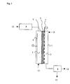
- FIG. 1 A suitable electrolytic cell for carrying out the method according to the invention is shown schematically in Fig. 1.
- the electrolysis cell 1 is divided by a cation exchange membrane 6 into a cathode chamber 2 with an oxygen-consuming cathode 5 and an anode chamber 3 with an anode 4 .
- the oxygen-consuming cathode 5 is located on the cathode side on the cation exchange membrane 6 .
- Behind the Sauerstoffverzehrkathode 5 is a power distributor. 7 Due to the higher pressure in the anode chamber 3 , the cation exchange membrane 6 is pressed onto the oxygen-consuming cathode 5 and this in turn onto the current distributor 7 . In this way, the Sauerstoffverzehrkathode 5 is sufficiently electrically contacted and supplied with power.
- the adjustment of the pressure in the cathode chamber 2 and anode chamber 3 is in each case via a pressure maintenance 8 via an HCl inlet 12 , an aqueous solution of hydrogen chloride is introduced into the anode chamber 3 , which forms at the anode 4 chlorine, which flows through the pressure maintenance 8 and is discharged from the anode chamber 3 via the Cl 2 outlet 13 .
- oxygen-containing gas is introduced into the cathode chamber 2 , where it reacts with the oxygen-consuming cathode 5 to form water with protons which diffuse out of the anode chamber 3 into the oxygen-consuming cathode 5 .
- the water formed is removed together with the excess oxygen-containing gas via the pressure maintenance 8 from the cathode chamber 2 , wherein the water formed via a H 2 O outlet 11 and the oxygen-containing gas via an O 2 outlet 10 is removed. It is also possible that the oxygen supply is from below and / or that the removal of water formed and oxygen-containing gas is carried out separately via a separate pressure maintenance.
- the electrolysis was carried out in an electrolysis cell 1 divided into a cathode chamber 2 and an anode chamber 3 , as shown schematically in FIG. 1 and explained in greater detail above.
- An activated titanium anode with a size of 10 cm ⁇ 10 cm was used as anode 4 .
- the anode chamber 3 was supplied with an aqueous solution of hydrogen chloride.
- the temperature of the aqueous solution of hydrogen chloride was 60 ° C, the concentration 12-15 wt .-%.
- a gas diffusion electrode of the company E-TEK, type ELAT which was directly on a power distributor 7 in the form of an activated expanded titanium metal.
- Cathode chamber 2 and anode chamber 3 were separated from a cation exchange membrane 6 from DuPont, type Nafion® 324.
- pure oxygen having a content of greater than 99 vol .-% was introduced at a temperature of 20 ° C.
- the electrolysis was at a pressure in the anode chamber 3 of 1 , 4 bar, abs. and a pressure in the cathode chamber 2 of 1 bar, abs., A voltage of 1.67 V and a current density of 6000 A / m 2 operated.
- the excess oxygen-containing gas was removed from the cathode chamber 2 together with the water formed.
- the concentration of hydrogen in this gas was determined by gas chromatography. The hydrogen concentration was 700 ppm after an electrolysis time of 10 minutes, increased steadily during the electrolysis and was 1600 ppm after an electrolysis time of 3 hours.
- Example 1 An electrolysis of an aqueous solution of hydrogen chloride was carried out as described in Example 1.
- the pressure in the anode chamber 3 was 1.4 bar, abs.,
- the pressure in the cathode chamber 2 1 bar, abs.,
- the voltage 1.82 V and the current density 7000 A / m 2 were measured.
Abstract
Description
Die Erfindung betrifft ein Verfahren zur elektrochemischen Herstellung von Chlor aus wässrigen Lösungen von Chlorwasserstoff in einer Elektrolysezelle.The invention relates to a method for the electrochemical production of chlorine from aqueous solutions of hydrogen chloride in an electrolytic cell.
Wässrige Lösungen von Chlorwasserstoff (Salzsäuren) fallen beispielsweise als Nebenprodukte bei der Herstellung von organischen Chlorverbindungen durch Chlorierung mit elementarem Chlor an. Viele dieser organischen Chlorverbindungen sind Zwischenprodukte für die großtechnische Herstellung von Kunststoffen. Die anfallenden wässrigen Lösungen von Chlorwasserstoff müssen einer Verwertung zugeführt werden. Vorzugsweise erfolgt die Verwertung dergestalt, dass aus den wässrigen Lösungen von Chlorwasserstoff wieder Chlor hergestellt wird, das dann beispielsweise für weitere Chlorierungen eingesetzt werden kann.Aqueous solutions of hydrogen chloride (hydrochloric acids) fall for example as By-products in the production of organic chlorine compounds by Chlorination with elemental chlorine. Many of these organic chlorine compounds are intermediates for the large-scale production of plastics. The Any aqueous solutions of hydrogen chloride must be recycled be supplied. Preferably, the recovery takes place in such a way that from the aqueous solutions of hydrogen chloride again chlorine is produced, which then can be used for example for further chlorinations.
Die Umsetzung zu Chlor kann z.B. durch Elektrolyse der wässrigen Lösungen von Chlorwasserstoff an einer Gasdiffusionskathode erfolgen. Ein entsprechendes Verfahren ist aus US-A-5 770 035 bekannt. Die Elektrolyse erfolgt gemäß US-A-5 770 035 in einer Elektrolysezelle mit einem Anodenraum, mit einer geeigneten Anode, z.B. einer edelmetallbeschichteten bzw. -dotierten Titanelektrode, der mit der wässrigen Lösung von Chlorwasserstoff gefüllt wird. Das an der Anode gebildete Chlor entweicht aus dem Anodenraum und wird einer geeigneten Aufbereitung zugeführt. Der Anodenraum ist von einem Kathodenraum durch eine handelsübliche Kationenaustauschermembran getrennt. Auf der Kathodenseite liegt eine Gasdiffusionselektrode auf der Kationenaustauschermembran auf. Hinter der Gasdiffusionselektrode befindet sich ein Stromverteiler. In den Kathodenraum wird üblicherweise ein Sauerstoff-haltiges Gas oder reiner Sauerstoff eingeleitet.The conversion to chlorine can e.g. by electrolysis of the aqueous solutions of Hydrogen chloride take place on a gas diffusion cathode. A corresponding Method is known from US-A-5 770 035. The electrolysis is carried out according to US-A-5 770 035 in an electrolytic cell with an anode compartment, with a suitable Anode, e.g. a noble metal coated or doped titanium electrode, with the aqueous solution of hydrogen chloride is filled. The one formed at the anode Chlorine escapes from the anode compartment and becomes suitable treatment fed. The anode compartment is from a cathode compartment by a commercially available Cation exchange membrane separated. On the cathode side is a gas diffusion electrode on the cation exchange membrane. Behind the gas diffusion electrode there is a power distributor. In the cathode compartment is usually an oxygen-containing gas or pure oxygen introduced.
Der Anodenraum wird auf einem höheren Druck gehalten als der Kathodenraum. Dadurch wird die Kationenaustauschermembran auf die Gasdiffusionskathode und diese wiederum auf den Stromverteiler gedrückt. Die Einstellung des Drucks kann z.B. durch eine Flüssigkeitstauchung erfolgen, durch die das in der Anodenkammer gebildete Chlorgas geleitet wird.The anode compartment is maintained at a higher pressure than the cathode compartment. As a result, the cation exchange membrane on the gas diffusion cathode and these in turn pressed on the power distributor. The setting of the pressure can e.g. done by a liquid immersion, through which in the anode chamber formed chlorine gas is passed.
Das aus US-A-5 770 035 bekannte Verfahren hat den Nachteil, dass bei hohen Stromdichten, worunter insbesondere Stromdichten größer als 4000 A/m2 zu verstehen sind, an der Gasdiffusionskathode eine vergleichsweise hohe Menge Wasserstoff gebildet wird. Hohe Stromdichten sind jedoch bei der technischen Durchführung des Verfahrens aus wirtschaftlichen Gründen notwendig. Außerdem stellt sich bei hohen Stromdichten eine vergleichsweise hohe Spannung ein, was einen hohen Energieverbrauch bedingt.The US-A-5,770,035 known method has the drawback, that at high current densities, including in particular current densities greater than 4000 A / m 2 are understood to be formed on the gas diffusion cathode, a relatively high amount of hydrogen. However, high current densities are necessary in the technical implementation of the method for economic reasons. In addition, at high current densities, a comparatively high voltage sets in, which requires high energy consumption.
Aufgabe der Erfindung ist die Bereitstellung eines Verfahrens zur elektrochemischen Herstellung von Chlor aus wässrigen Lösungen von Chlorwasserstoff, wobei selbst beim Arbeiten mit hohen Stromdichten möglichst wenig Wasserstoff gebildet wird und sich eine möglichst niedrige Spannung einstellt.The object of the invention is to provide a method for electrochemical Production of chlorine from aqueous solutions of hydrogen chloride, using itself When working with high current densities, as little hydrogen as possible is formed and sets the lowest possible voltage.
Gegenstand der Erfindung ist ein Verfahren zur elektrochemischen Herstellung von Chlor aus wässrigen Lösungen von Chlorwasserstoff in einer Elektrolysezelle, umfassend mindestens eine Anodenkammer und eine Kathodenkammer, wobei die Anodenkammer durch eine Kationenaustauschermembran von der Kathodenkammer getrennt ist, die Anodenkammer eine Anode und die Kathodenkammer eine Sauerstoffverzehrkathode enthält, und in die Anodenkammer die wässrige Lösung von Chlorwasserstoff und in die Kathodenkammer ein sauerstoffhaltiges Gas eingeleitet wird, wobei der absolute Druck in der Kathodenkammer mindestens 1,05 bar beträgt.The invention relates to a process for the electrochemical production of Chlorine from aqueous solutions of hydrogen chloride in an electrolytic cell, comprising at least one anode chamber and a cathode chamber, wherein the Anodenkammer through a cation exchange membrane of the cathode chamber is separated, the anode chamber an anode and the cathode chamber an oxygen-consuming cathode contains, and in the anode chamber, the aqueous solution of Hydrogen chloride and introduced into the cathode chamber, an oxygen-containing gas is, wherein the absolute pressure in the cathode chamber is at least 1.05 bar.
Durch den erfindungsgemäß leicht erhöhten Druck in der Kathodenkammer wird die Bildung von Wasserstoff an der Sauerstoffverzehrkathode vermindert und zudem eine niedrigere Elektrolysespannung erzielt, als bei Reaktionsführung unter Normaldruck, entsprechend dem Umgebungsdruck, in der Kathodenkammer. Es ist erstaunlich und war nicht zu erwarten, dass bereits eine vergleichsweise geringe Erhöhung des Drucks in der Kathodenkammer zu einer deutlichen Reduzierung der unerwünschten Wasserstoffentwicklung an der Sauerstoffverzehrkathode und zu niedrigeren Elektrolysespannungen führt, was wiederum hinsichtlich des Energieverbrauchs vorteilhaft ist.Due to the inventively slightly increased pressure in the cathode chamber is the Formation of hydrogen at the oxygen-consuming cathode reduced and also achieved a lower electrolysis than in reaction under normal pressure, according to the ambient pressure, in the cathode chamber. It is amazing and was not expected to have a comparatively small increase the pressure in the cathode chamber to a significant reduction of unwanted hydrogen evolution at the oxygen-consuming cathode and to lower electrolytic voltages, which in turn results in energy consumption is advantageous.
Als sauerstoffhaltiges Gas kann beispielsweise reiner Sauerstoff, ein Gemisch aus Sauerstoff und inerten Gasen, insbesondere Stickstoff, oder Luft eingesetzt werden. Bevorzugt wird als sauerstoffhaltiges Gas reiner Sauerstoff, insbesondere einer Reinheit von mind. 99 Vol.-% eingesetzt.As the oxygen-containing gas, for example, pure oxygen, a mixture of Oxygen and inert gases, in particular nitrogen, or air are used. Preferred oxygen-containing gas is pure oxygen, in particular a purity used by at least 99 vol .-%.
Bei der Angabe des Drucks in der Kathodenkammer handelt es sich um Absolutwerte. Bevorzugt beträgt der Druck in der Kathodenkammer 1,05 bis 1,5 bar, insbesondere bevorzugt 1,05 bis 1,3 bar.The indication of the pressure in the cathode chamber are absolute values. The pressure in the cathode chamber is preferably 1.05 to 1.5 bar, especially preferably 1.05 to 1.3 bar.
Die Einstellung des Drucks in der Kathodenkammer auf den erfindungsgemäßen Wert von mindestens 1,05 bar kann beispielsweise dadurch erfolgen, dass das der Kathodenkammer zugeführte sauerstoffhaltige Gas durch eine Druckhaltevorrichtung angestaut wird. Eine geeignete Druckhaltevorrichtung ist beispielsweise eine Flüssigkeitstauchung, durch die der Kathodenraum abgesperrt wird. Ein Androsselung über Ventile stellt ebenfalls eine geeignete Methode zur Einstellung des Drucks im Kathodenraum dar.The adjustment of the pressure in the cathode chamber on the inventive Value of at least 1.05 bar can be done, for example, that the Cathode chamber supplied oxygen-containing gas through a pressure holding device is accumulated. A suitable pressure holding device is for example a Fluid compression, through which the cathode space is shut off. A throttling About valves also provides a suitable method for adjusting the Pressure in the cathode compartment.
Um einen hinreichenden Kontakt zwischen Kationenaustauschermembran und Sauerstoffverzehrkathode zu gewährleisten, wird vorzugsweise in der Anodenkammer ein Druck eingestellt, der 0,01 bis 1000 mbar höher ist als der Druck in der Kathodenkammer.To ensure adequate contact between cation exchange membrane and To ensure oxygen-consuming cathode is preferably in the anode compartment set a pressure that is 0.01 to 1000 mbar higher than the pressure in the Cathode chamber.
Insbesondere bevorzugt ist der Druck in der Anodenkammer 50 bis 500 mbar, ganz besonders bevorzugt 200 bis 500 mbar höher als der Druck in der Kathodenkammer. Particularly preferably, the pressure in the anode chamber is 50 to 500 mbar, completely more preferably 200 to 500 mbar higher than the pressure in the cathode chamber.
Vorzugsweise wird das erfindungsgemäße Verfahren bei einer Stromdichte von mindestens 3500 A/m2 betrieben, besonders bevorzugt bei einer Stromdichte von mindestens 4000 A/m2, insbesondere bevorzugt bei einer Stromdichte von mindestens 5000 A/m2.The process according to the invention is preferably operated at a current density of at least 3500 A / m 2 , more preferably at a current density of at least 4000 A / m 2 , particularly preferably at a current density of at least 5000 A / m 2 .
Die Temperatur der zugeführten wässrigen Lösung von Chlorwasserstoff beträgt vorzugsweise 30 bis 80°C, insbesondere bevorzugt 50 bis 70°C.The temperature of the supplied aqueous solution of hydrogen chloride is preferably 30 to 80 ° C, particularly preferably 50 to 70 ° C.
Vorzugsweise beträgt die Konzentration der Salzsäure im Elektrolyseur bei der
Durchführung des erfindungsgemäßen Verfahrens 5 bis 20 Gew.-%, besonders
bevorzugt 10 bis 15 Gew.-%. Die verbrauchte Salzsäure im Elektrolyseur kann durch
eine dem Elektrolyseur zugeführte Salzsäure in Konzentrationsbereich von 8 bis
36 Gew.-% ergänzt werden.Preferably, the concentration of hydrochloric acid in the electrolyzer in the
Carrying out the process according to the
Das sauerstoffhaltige Gas wird bevorzugt in einer solchen Menge zugeführt, dass Sauerstoff bezogen auf die theoretisch benötigte Menge im Überschuss vorliegt. Besonders bevorzugt ist ein 1,2 bis 1,5 facher Überschuß an Sauerstoff.The oxygen-containing gas is preferably supplied in such an amount that Oxygen in excess of the theoretically required amount is present. Particularly preferred is a 1.2 to 1.5-fold excess of oxygen.
Das erfindungsgemäße Verfahren wird in einer elektrochemischen Zelle (Elektrolysezelle) durchgeführt, deren Anodenkammer durch eine Kationenaustauschermembran von der Kathodenkammer getrennt ist, wobei die Kathodenkammer eine Sauerstoffverzehrkathode enthält.The process according to the invention is carried out in an electrochemical cell (electrolysis cell) performed, the anode compartment through a cation exchange membrane is separated from the cathode chamber, wherein the cathode chamber a Contains oxygen-consuming cathode.
Die verwendete Elektrolysezelle kann beispielsweise folgende Komponenten umfassen: eine Anode in einer Andodenkammer, eine Kationenaustauschermembran, die hydrostatisch auf eine Sauerstoffverzehrkathode (SVK) aufgepresst wird, die sich wiederum auf einen kathodenseitigen Stromverteiler abstützt und so elektrisch kontaktiert wird, sowie einen kathodenseitigen Gasraum (Kathodenkammer).The electrolysis cell used may, for example, the following components comprising: an anode in an anode chamber, a cation exchange membrane, which is hydrostatically pressed onto an oxygen-consuming cathode (SVK), which itself in turn supported on a cathode-side power distributor and so electrically is contacted, and a cathode-side gas space (cathode chamber).
Die wässrige Lösung des Chlorwasserstoffs wird in die Anodenkammer eingeleitet, das sauerstoffhaltige Gas in die Kathodenkammer. The aqueous solution of hydrogen chloride is introduced into the anode chamber, the oxygen-containing gas in the cathode chamber.
Die Wahl der Sauerstoffverzehrkathode ist nicht kritisch. Es können die bekannten und zum Teil kommerziell verfügbaren Sauerstoffverzehrkathoden eingesetzt werden. Vorzugsweise werden jedoch Sauerstoffverzehrkathoden eingesetzt, die einen Katalysator der Platingruppe, vorzugsweise Platin oder Rhodium enthalten.The choice of the oxygen-consuming cathode is not critical. It can be the well-known and partially commercially available oxygen-consuming cathodes are used. Preferably, however, oxygen-consuming cathodes are used which have a Catalyst of the platinum group, preferably platinum or rhodium.
Als Kationenaustauschermembran eignen sich beispielsweise solche aus Perfluorethylen, die als aktive Zentren Sulfonsäuregruppen enthalten. Es sind sowohl Einschichten-Membranen, die beidseitig Sulfonsäuregruppen mit gleichen Äquivalentgewichten haben, als auch Membranen, die auf beiden Seiten Sulfonsäuregruppen mit unterschiedlichen Äquivalentgewichten haben, geeignet. Ebenfalls sind Membranen mit Carboxylgruppen auf der Kathodenseite denkbar.Examples of suitable cation exchange membranes are those made of perfluoroethylene, which contain sulfonic acid groups as active centers. They are both Single-layer membranes containing sulfonic acid groups with equal equivalent weights on both sides have, as well as membranes, sulfonic acid groups on both sides with different equivalent weights are suitable. Also Membranes with carboxyl groups on the cathode side are conceivable.
Geeignete Anoden sind beispielsweise Titananoden, insbesondere mit einer säurefesten, Chlor-entwickelnden Beschichtung.Suitable anodes are, for example, titanium anodes, in particular with a acid-resistant, chlorine-evolving coating.
Der kathodenseitige Stromverteiler kann beispielsweise aus Titan-Streckmetall oder edelmetallbeschichtetem Titan bestehen.The cathode-side power distributor can be made of titanium expanded metal or made of precious metal coated titanium.
Eine geeignete Elektrolysezelle zur Durchführung des erfindungsgemäßen Verfahrens ist schematisch in Fig. 1 dargestellt.A suitable electrolytic cell for carrying out the method according to the invention is shown schematically in Fig. 1.
Die Elektrolysezelle 1 ist durch eine Kationenaustauschermembran 6 in eine
Kathodenkammer 2 mit Sauerstoffverzehrkathode 5 und eine Anodenkammer 3 mit
Anode 4 unterteilt. Die Sauerstoffverzehrkathode 5 liegt kathodenseitig auf der
Kationenaustauschermembran 6 auf. Hinter der Sauerstoffverzehrkathode 5 befindet
sich ein Stromverteiler 7. Durch den höheren Druck in der Anodenkammer 3 wird
die Kationenaustauschermembran 6 auf die Sauerstoffverzehrkathode 5 und diese
wiederum auf den Stromverteiler 7 gedrückt. Auf diese Weise wird die Sauerstoffverzehrkathode
5 hinreichend elektrisch kontaktiert und mit Strom versorgt. Die
Einstellung des Drucks in Kathodenkammer 2 und Anodenkammer 3 erfolgt jeweils
über eine Druckhaltung 8. Über einen HCl-Einlass 12 wird eine wässrigen Lösung
von Chlorwasserstoff in die Anodenkammer 3 eingeleitet, wobei sich an der Anode 4
Chlor bildet, das die Druckhaltung 8 durchströmt und über der Cl2-Auslass 13 aus
der Anodenkammer 3 abgeführt wird. Über einen O2-Einlass 9 wird sauerstoffhaltiges
Gas in die Kathodenkammer 2 eingeleitet, wo es sich an der
Sauerstoffverzehrkathode 5 unter Bildung von Wasser mit Protonen umsetzt, die aus
der Anodenkammer 3 in die Sauerstoffverzehrkathode 5 eindiffundieren. Das
gebildete Wasser wird gemeinsam mit dem überschüssigen sauerstoffhaltigen Gas
über die Druckhaltung 8 aus der Kathodenkammer 2 entfernt, wobei das gebildete
Wasser über einen H2O-Auslass 11 und das sauerstoffhaltige Gas über einen O2-Auslass
10 entnommen wird. Es ist auch möglich, dass die Sauerstoffzufuhr von
unten erfolgt und/oder dass die Entfernung von gebildeten Wasser und
sauerstoffhaltigem Gas getrennt über jeweils eine separate Druckhaltung
vorgenommen wird.The electrolysis cell 1 is divided by a
In den folgenden Beispielen wird das erfindungsgemäße Verfahren weiter erläutert, wobei die Beispiele nicht als Einschränkung des allgemeinen Erfindungsgedankens zu verstehen sind. In the following examples, the method according to the invention is explained further, the examples are not intended to limit the general inventive idea to be understood.
Die Elektrolyse wurde in einer in eine Kathodenkammer 2 und eine Anodenkammer
3 unterteilten Elektrolysezelle 1 durchgeführt, wie sie in Fig. 1 schematisch dargestellt
und oben näher erläutert ist. Als Anode 4 kam eine aktivierte Titan-Anode
mit einer Grösse von 10 cm * 10 cm zum Einsatz. Der Anodenkammer 3 wurde eine
wässrige Lösung von Chlorwasserstoff zugeführt. Die Temperatur der wässrigen
Lösung von Chlorwasserstoff betrug 60°C, die Konzentration 12-15 Gew.-%. In der
Kathodenkammer 2 befand sich als Sauerstoffverzehrkathode 5 eine Gasdiffusionselektrode
der Firma E-TEK, Typ ELAT, die unmittelbar auf einem Stromverteiler 7
in Form eines aktivierten Titan-Streckmetalls auflag. Kathodenkammer 2 und
Anodenkammer 3 wurden von einer Kationenaustauschermembran 6 der Firma
DuPont, Typ Nafion® 324, getrennt. In die Kathodenkammer 2 wurde reiner Sauerstoff
mit einem Gehalt von größer als 99 Vol.-% mit einer Temperatur von 20°C
eingeleitet.The electrolysis was carried out in an electrolysis cell 1 divided into a
Die Elektrolyse wurde bei einem Druck in der Anodenkammer 3 von 1,4 bar, abs.
und einem Druck in der Kathodenkammer 2 von 1 bar, abs., einer Spannung von 1,67
V und einer Stromdichte von 6000 A/m2 betrieben. Das überschüssige sauerstoffhaltige
Gas wurde gemeinsam mit dem gebildeten Wasser aus der Kathodenkammer
2 abgeführt. Es wurde die Konzentration an Wasserstoff in diesem Gas mittels
Gaschromatographie bestimmt. Die Wasserstoffkonzentration betrug nach einer
Elektrolysedauer von 10 Minuten 700 ppm, stieg im Laufe der Elektrolyse stetig an
und lag nach einer Elektrolysedauer von 3 Stunden bei 1600 ppm.The electrolysis was at a pressure in the
Es wurde eine Elektrolyse einer wässrigen Lösung von Chlorwasserstoff
durchgeführt, wie in Beispiel 1 beschrieben, wobei der Druck in der Anodenkammer
3 jedoch 1,15 bar, abs. betrug. Die Wasserstoffkonzentration betrug nach 10 Minuten
Elektrolysedauer 700 ppm, stieg im Lauf der Elektrolyse stetig an und lag nach 3
Stunden bei 1600 ppm.An electrolysis of an aqueous solution of hydrogen chloride was carried out as described in Example 1, the pressure in the
Es wurde eine Elektrolyse einer wässrigen Lösung von Chlorwasserstoff
durchgeführt, wie in Beispiel 1 beschrieben, wobei der Druck in der Kathodenkammer
2 jedoch 1,06 bar, abs. betrug und sich bei einer Stromdichte von 6000 A/m2
eine Spannung von 1,62 V einstellte. Die Wasserstoffkonzentration betrug 300 ppm
und blieb über den Zeitraum der Elektrolyse von mehreren Tagen konstant.An electrolysis of an aqueous solution of hydrogen chloride was carried out, as described in Example 1, wherein the pressure in the
Es wurde eine Elektrolyse einer wässrigen Lösung von Chlorwasserstoff durchgeführt,
wie in Beispiel 1 beschrieben. Der Druck in der Anodenkammer 3 betrug 1,4
bar, abs., der Druck in der Kathodenkammer 2 1 bar, abs., die Spannung 1,82 V und
die Stromdichte 7000 A/m2. Bereits nach einer Elektrolysedauer von 3 Minuten
wurde eine Wasserstoffkonzentration von 8000 ppm gemessen.An electrolysis of an aqueous solution of hydrogen chloride was carried out as described in Example 1. The pressure in the
Es wurde eine Elektrolyse einer wässrigen Lösung von Chlorwasserstoff durchgeführt,
wie in Beispiel 4 beschrieben, wobei der Druck in der Kathodenkammer 2
jedoch 1,12 bar, abs. betrug und sich bei der gewählten Stromdichte von 7000 A/m2
eine Spannung von 1,74 V einstellte. Die Wasserstoffkonzentration betrug 600 ppm
und blieb über den gesamten Zeitraum der Elektrolyse von mehreren Tagen konstant.It was carried out an electrolysis of an aqueous solution of hydrogen chloride, as described in Example 4, wherein the pressure in the
Claims (8)
Applications Claiming Priority (2)
| Application Number | Priority Date | Filing Date | Title |
|---|---|---|---|
| DE10138215 | 2001-08-03 | ||
| DE10138215A DE10138215A1 (en) | 2001-08-03 | 2001-08-03 | Process for the electrochemical production of chlorine from aqueous solutions of hydrogen chloride |
Publications (3)
| Publication Number | Publication Date |
|---|---|
| EP1283281A2 true EP1283281A2 (en) | 2003-02-12 |
| EP1283281A3 EP1283281A3 (en) | 2003-05-28 |
| EP1283281B1 EP1283281B1 (en) | 2012-11-14 |
Family
ID=7694329
Family Applications (1)
| Application Number | Title | Priority Date | Filing Date |
|---|---|---|---|
| EP02016239A Expired - Lifetime EP1283281B1 (en) | 2001-08-03 | 2002-07-22 | Process for the electrochemical production of chlorine from aqueous hydrochloric acid solutions |
Country Status (7)
| Country | Link |
|---|---|
| US (1) | US6790339B2 (en) |
| EP (1) | EP1283281B1 (en) |
| CN (1) | CN1247818C (en) |
| DE (1) | DE10138215A1 (en) |
| ES (1) | ES2397508T3 (en) |
| HK (1) | HK1054575A1 (en) |
| PT (1) | PT1283281E (en) |
Families Citing this family (14)
| Publication number | Priority date | Publication date | Assignee | Title |
|---|---|---|---|---|
| IL158618A0 (en) | 2001-04-27 | 2004-05-12 | Univ Johns Hopkins | Biological pacemaker |
| DE10152275A1 (en) * | 2001-10-23 | 2003-04-30 | Bayer Ag | Process for the electrolysis of aqueous solutions of hydrogen chloride |
| WO2004048643A1 (en) * | 2002-11-27 | 2004-06-10 | Asahi Kasei Chemicals Corporation | Bipolar zero-gap electrolytic cell |
| DE10342148A1 (en) | 2003-09-12 | 2005-04-07 | Bayer Materialscience Ag | Process for the electrolysis of an aqueous solution of hydrogen chloride or alkali chloride |
| DE102006023261A1 (en) | 2006-05-18 | 2007-11-22 | Bayer Materialscience Ag | Process for the production of chlorine from hydrogen chloride and oxygen |
| JP5041769B2 (en) * | 2006-09-06 | 2012-10-03 | 住友化学株式会社 | Startup method |
| DE102008015901A1 (en) * | 2008-03-27 | 2009-10-01 | Bayer Technology Services Gmbh | Electrolysis cell for hydrogen chloride electrolysis |
| US9181624B2 (en) | 2009-04-16 | 2015-11-10 | Chlorine Engineers Corp., Ltd. | Method of electrolysis employing two-chamber ion exchange membrane electrolytic cell having gas diffusion electrode |
| DE102009023539B4 (en) * | 2009-05-30 | 2012-07-19 | Bayer Materialscience Aktiengesellschaft | Method and device for the electrolysis of an aqueous solution of hydrogen chloride or alkali chloride in an electrolytic cell |
| US9175135B2 (en) | 2010-03-30 | 2015-11-03 | Bayer Materialscience Ag | Process for preparing diaryl carbonates and polycarbonates |
| SG174714A1 (en) | 2010-03-30 | 2011-10-28 | Bayer Materialscience Ag | Process for preparing diaryl carbonates and polycarbonates |
| US8562810B2 (en) | 2011-07-26 | 2013-10-22 | Ecolab Usa Inc. | On site generation of alkalinity boost for ware washing applications |
| CN103194765A (en) * | 2012-01-10 | 2013-07-10 | 石福金属兴业株式会社 | Sterilizing water generation apparatus |
| WO2014000030A1 (en) * | 2012-06-29 | 2014-01-03 | Australian Biorefining Pty Ltd | Process and apparatus for generating or recovering hydrochloric acid from metal salt solutions |
Citations (2)
| Publication number | Priority date | Publication date | Assignee | Title |
|---|---|---|---|---|
| EP0785294A1 (en) * | 1996-01-19 | 1997-07-23 | De Nora S.P.A. | Improved method for the electrolysis of aqueous solutions of hydrochloric acid |
| US6149782A (en) * | 1999-05-27 | 2000-11-21 | De Nora S.P.A | Rhodium electrocatalyst and method of preparation |
Family Cites Families (3)
| Publication number | Priority date | Publication date | Assignee | Title |
|---|---|---|---|---|
| JPS534796A (en) * | 1976-07-05 | 1978-01-17 | Asahi Chem Ind Co Ltd | Electrolysis of pressurized alkali halide |
| US4311568A (en) * | 1980-04-02 | 1982-01-19 | General Electric Co. | Anode for reducing oxygen generation in the electrolysis of hydrogen chloride |
| US6135331A (en) * | 1999-08-13 | 2000-10-24 | Davis; Richard Maurice | Snow ski boot remover |
-
2001
- 2001-08-03 DE DE10138215A patent/DE10138215A1/en not_active Withdrawn
-
2002
- 2002-07-22 EP EP02016239A patent/EP1283281B1/en not_active Expired - Lifetime
- 2002-07-22 PT PT2016239T patent/PT1283281E/en unknown
- 2002-07-22 ES ES02016239T patent/ES2397508T3/en not_active Expired - Lifetime
- 2002-07-30 US US10/207,937 patent/US6790339B2/en not_active Expired - Lifetime
- 2002-08-02 CN CNB021274622A patent/CN1247818C/en not_active Expired - Lifetime
-
2003
- 2003-09-18 HK HK03106703.2A patent/HK1054575A1/en unknown
Patent Citations (2)
| Publication number | Priority date | Publication date | Assignee | Title |
|---|---|---|---|---|
| EP0785294A1 (en) * | 1996-01-19 | 1997-07-23 | De Nora S.P.A. | Improved method for the electrolysis of aqueous solutions of hydrochloric acid |
| US6149782A (en) * | 1999-05-27 | 2000-11-21 | De Nora S.P.A | Rhodium electrocatalyst and method of preparation |
Also Published As
| Publication number | Publication date |
|---|---|
| EP1283281A3 (en) | 2003-05-28 |
| CN1405357A (en) | 2003-03-26 |
| HK1054575A1 (en) | 2003-12-05 |
| CN1247818C (en) | 2006-03-29 |
| US20030024824A1 (en) | 2003-02-06 |
| EP1283281B1 (en) | 2012-11-14 |
| JP4251432B2 (en) | 2009-04-08 |
| JP2003049290A (en) | 2003-02-21 |
| US6790339B2 (en) | 2004-09-14 |
| ES2397508T3 (en) | 2013-03-07 |
| DE10138215A1 (en) | 2003-02-20 |
| PT1283281E (en) | 2013-01-24 |
Similar Documents
| Publication | Publication Date | Title |
|---|---|---|
| EP0866890B1 (en) | Process for direct electrochemical gaseous phase phosgene synthesis | |
| EP0989206B1 (en) | Electrolysis cell and use thereof | |
| EP1283281B1 (en) | Process for the electrochemical production of chlorine from aqueous hydrochloric acid solutions | |
| EP1417356B1 (en) | Electrolysis cell, particularly for electrochemically producing chlorine | |
| EP1463847B1 (en) | Electrode for conducting electrolysis in acid media | |
| DD140262A5 (en) | METHOD FOR CONTINUOUS PRODUCTION OF CHLORINE | |
| EP0391192A2 (en) | Electrolytic process for manufacturing alkali dichromates and chromic acid | |
| EP4041939A1 (en) | Method and electrolysis device for the production of chlorine, carbon monoxide and optionally hydrogen | |
| EP1953272A1 (en) | Method for electrochemical dechlorination of anolyte brine from NaCl electrolysis | |
| DE102017219974A1 (en) | Production and separation of phosgene by combined CO2 and chloride electrolysis | |
| EP0234256B1 (en) | Process for carrying out hcl membrane electrolysis | |
| EP0008470B1 (en) | Process for the electrolysis of aqueous alkali metal halide solutions | |
| DE10152275A1 (en) | Process for the electrolysis of aqueous solutions of hydrogen chloride | |
| EP3597791B1 (en) | Method for improving the performance of nickel electrodes | |
| DD271722A5 (en) | ELECTROCHEMICAL METHOD FOR THE PRODUCTION OF HYDROCARBON HYDROGEN | |
| EP1167579B1 (en) | Chlor-alkali electrolytic process in membrane cells using non-purified salt | |
| EP0141905B1 (en) | Process for the electrochemical compensation of the oxidation in the electrochemical regeneration of copper etching solutions containing chloride | |
| DE10138966A1 (en) | Electrochemical decomposition of an aqueous ammonium salt solution to form ammonia and an inorganic acid used in the recovery of metals is carried out in an electrochemical cell having a cation exchange membrane | |
| EP1106714B1 (en) | Gas phase electrolytic generation of halogen | |
| EP0356806B1 (en) | Process for the production of chromic acid | |
| EP0029083A1 (en) | Process for the simultaneous production of nitrogen monoxide and alkali hydroxide from aqueous solutions of alkali nitrite by electrolysis | |
| WO2017174563A1 (en) | Difunctional electrode and electrolysis device for chlor-alkali electrolysis | |
| DE2942863A1 (en) | Chlorine recovery from soln. in electrolyte from membrane cell - for brine electrolysis by adding alkali and reacting chlorate formed with hydrogen chloride |
Legal Events
| Date | Code | Title | Description |
|---|---|---|---|
| PUAI | Public reference made under article 153(3) epc to a published international application that has entered the european phase |
Free format text: ORIGINAL CODE: 0009012 |
|
| AK | Designated contracting states |
Designated state(s): AT BE BG CH CY CZ DE DK EE ES FI FR GB GR IE IT LI LU MC NL PT SE SK TR |
|
| AX | Request for extension of the european patent |
Extension state: AL LT LV MK RO SI |
|
| PUAL | Search report despatched |
Free format text: ORIGINAL CODE: 0009013 |
|
| AK | Designated contracting states |
Designated state(s): AT BE BG CH CY CZ DE DK EE ES FI FR GB GR IE IT LI LU MC NL PT SE SK TR |
|
| AX | Request for extension of the european patent |
Extension state: AL LT LV MK RO SI |
|
| 17P | Request for examination filed |
Effective date: 20031128 |
|
| AKX | Designation fees paid |
Designated state(s): AT BE BG CH CY CZ DE DK EE ES FI FR GB GR IE IT LI LU MC NL PT SE SK TR |
|
| RAP1 | Party data changed (applicant data changed or rights of an application transferred) |
Owner name: BAYER MATERIALSCIENCE AG |
|
| 17Q | First examination report despatched |
Effective date: 20100714 |
|
| RTI1 | Title (correction) |
Free format text: PROCESS FOR THE ELECTROCHEMICAL PRODUCTION OF CHLORINE FROM AQUEOUS HYDROCHLORIC ACID SOLUTIONS |
|
| GRAP | Despatch of communication of intention to grant a patent |
Free format text: ORIGINAL CODE: EPIDOSNIGR1 |
|
| GRAS | Grant fee paid |
Free format text: ORIGINAL CODE: EPIDOSNIGR3 |
|
| GRAA | (expected) grant |
Free format text: ORIGINAL CODE: 0009210 |
|
| AK | Designated contracting states |
Kind code of ref document: B1 Designated state(s): AT BE BG CH CY CZ DE DK EE ES FI FR GB GR IE IT LI LU MC NL PT SE SK TR |
|
| REG | Reference to a national code |
Ref country code: GB Ref legal event code: FG4D Free format text: NOT ENGLISH |
|
| REG | Reference to a national code |
Ref country code: AT Ref legal event code: REF Ref document number: 584067 Country of ref document: AT Kind code of ref document: T Effective date: 20121115 Ref country code: CH Ref legal event code: EP |
|
| REG | Reference to a national code |
Ref country code: IE Ref legal event code: FG4D Free format text: LANGUAGE OF EP DOCUMENT: GERMAN |
|
| REG | Reference to a national code |
Ref country code: DE Ref legal event code: R096 Ref document number: 50215645 Country of ref document: DE Effective date: 20130110 |
|
| REG | Reference to a national code |
Ref country code: PT Ref legal event code: SC4A Free format text: AVAILABILITY OF NATIONAL TRANSLATION Effective date: 20130111 |
|
| REG | Reference to a national code |
Ref country code: NL Ref legal event code: T3 |
|
| REG | Reference to a national code |
Ref country code: ES Ref legal event code: FG2A Ref document number: 2397508 Country of ref document: ES Kind code of ref document: T3 Effective date: 20130307 |
|
| PG25 | Lapsed in a contracting state [announced via postgrant information from national office to epo] |
Ref country code: FI Free format text: LAPSE BECAUSE OF FAILURE TO SUBMIT A TRANSLATION OF THE DESCRIPTION OR TO PAY THE FEE WITHIN THE PRESCRIBED TIME-LIMIT Effective date: 20121114 Ref country code: SE Free format text: LAPSE BECAUSE OF FAILURE TO SUBMIT A TRANSLATION OF THE DESCRIPTION OR TO PAY THE FEE WITHIN THE PRESCRIBED TIME-LIMIT Effective date: 20121114 |
|
| RAP2 | Party data changed (patent owner data changed or rights of a patent transferred) |
Owner name: BAYER INTELLECTUAL PROPERTY GMBH |
|
| PG25 | Lapsed in a contracting state [announced via postgrant information from national office to epo] |
Ref country code: GR Free format text: LAPSE BECAUSE OF FAILURE TO SUBMIT A TRANSLATION OF THE DESCRIPTION OR TO PAY THE FEE WITHIN THE PRESCRIBED TIME-LIMIT Effective date: 20130215 Ref country code: CY Free format text: LAPSE BECAUSE OF FAILURE TO SUBMIT A TRANSLATION OF THE DESCRIPTION OR TO PAY THE FEE WITHIN THE PRESCRIBED TIME-LIMIT Effective date: 20121114 |
|
| PG25 | Lapsed in a contracting state [announced via postgrant information from national office to epo] |
Ref country code: BG Free format text: LAPSE BECAUSE OF FAILURE TO SUBMIT A TRANSLATION OF THE DESCRIPTION OR TO PAY THE FEE WITHIN THE PRESCRIBED TIME-LIMIT Effective date: 20130214 Ref country code: EE Free format text: LAPSE BECAUSE OF FAILURE TO SUBMIT A TRANSLATION OF THE DESCRIPTION OR TO PAY THE FEE WITHIN THE PRESCRIBED TIME-LIMIT Effective date: 20121114 Ref country code: CZ Free format text: LAPSE BECAUSE OF FAILURE TO SUBMIT A TRANSLATION OF THE DESCRIPTION OR TO PAY THE FEE WITHIN THE PRESCRIBED TIME-LIMIT Effective date: 20121114 Ref country code: SK Free format text: LAPSE BECAUSE OF FAILURE TO SUBMIT A TRANSLATION OF THE DESCRIPTION OR TO PAY THE FEE WITHIN THE PRESCRIBED TIME-LIMIT Effective date: 20121114 Ref country code: DK Free format text: LAPSE BECAUSE OF FAILURE TO SUBMIT A TRANSLATION OF THE DESCRIPTION OR TO PAY THE FEE WITHIN THE PRESCRIBED TIME-LIMIT Effective date: 20121114 |
|
| PLBE | No opposition filed within time limit |
Free format text: ORIGINAL CODE: 0009261 |
|
| STAA | Information on the status of an ep patent application or granted ep patent |
Free format text: STATUS: NO OPPOSITION FILED WITHIN TIME LIMIT |
|
| 26N | No opposition filed |
Effective date: 20130815 |
|
| REG | Reference to a national code |
Ref country code: DE Ref legal event code: R097 Ref document number: 50215645 Country of ref document: DE Effective date: 20130815 |
|
| BERE | Be: lapsed |
Owner name: BAYER MATERIALSCIENCE A.G. Effective date: 20130731 |
|
| PG25 | Lapsed in a contracting state [announced via postgrant information from national office to epo] |
Ref country code: MC Free format text: LAPSE BECAUSE OF FAILURE TO SUBMIT A TRANSLATION OF THE DESCRIPTION OR TO PAY THE FEE WITHIN THE PRESCRIBED TIME-LIMIT Effective date: 20121114 |
|
| REG | Reference to a national code |
Ref country code: CH Ref legal event code: PL |
|
| GBPC | Gb: european patent ceased through non-payment of renewal fee |
Effective date: 20130722 |
|
| REG | Reference to a national code |
Ref country code: IE Ref legal event code: MM4A |
|
| REG | Reference to a national code |
Ref country code: FR Ref legal event code: ST Effective date: 20140331 |
|
| PG25 | Lapsed in a contracting state [announced via postgrant information from national office to epo] |
Ref country code: CH Free format text: LAPSE BECAUSE OF NON-PAYMENT OF DUE FEES Effective date: 20130731 Ref country code: GB Free format text: LAPSE BECAUSE OF NON-PAYMENT OF DUE FEES Effective date: 20130722 Ref country code: LI Free format text: LAPSE BECAUSE OF NON-PAYMENT OF DUE FEES Effective date: 20130731 Ref country code: BE Free format text: LAPSE BECAUSE OF NON-PAYMENT OF DUE FEES Effective date: 20130731 |
|
| PG25 | Lapsed in a contracting state [announced via postgrant information from national office to epo] |
Ref country code: FR Free format text: LAPSE BECAUSE OF NON-PAYMENT OF DUE FEES Effective date: 20130731 |
|
| REG | Reference to a national code |
Ref country code: DE Ref legal event code: R081 Ref document number: 50215645 Country of ref document: DE Owner name: COVESTRO DEUTSCHLAND AG, DE Free format text: FORMER OWNER: BAYER AG, 51373 LEVERKUSEN, DE Effective date: 20121031 Ref country code: DE Ref legal event code: R081 Ref document number: 50215645 Country of ref document: DE Owner name: COVESTRO DEUTSCHLAND AG, DE Free format text: FORMER OWNER: BAYER MATERIALSCIENCE AG, 51373 LEVERKUSEN, DE Effective date: 20140526 Ref country code: DE Ref legal event code: R081 Ref document number: 50215645 Country of ref document: DE Owner name: BAYER INTELLECTUAL PROPERTY GMBH, DE Free format text: FORMER OWNER: BAYER AG, 51373 LEVERKUSEN, DE Effective date: 20121031 Ref country code: DE Ref legal event code: R081 Ref document number: 50215645 Country of ref document: DE Owner name: BAYER INTELLECTUAL PROPERTY GMBH, DE Free format text: FORMER OWNER: BAYER MATERIALSCIENCE AG, 51373 LEVERKUSEN, DE Effective date: 20140526 |
|
| PG25 | Lapsed in a contracting state [announced via postgrant information from national office to epo] |
Ref country code: IE Free format text: LAPSE BECAUSE OF NON-PAYMENT OF DUE FEES Effective date: 20130722 |
|
| REG | Reference to a national code |
Ref country code: AT Ref legal event code: MM01 Ref document number: 584067 Country of ref document: AT Kind code of ref document: T Effective date: 20130722 |
|
| PG25 | Lapsed in a contracting state [announced via postgrant information from national office to epo] |
Ref country code: AT Free format text: LAPSE BECAUSE OF NON-PAYMENT OF DUE FEES Effective date: 20130722 |
|
| PG25 | Lapsed in a contracting state [announced via postgrant information from national office to epo] |
Ref country code: TR Free format text: LAPSE BECAUSE OF FAILURE TO SUBMIT A TRANSLATION OF THE DESCRIPTION OR TO PAY THE FEE WITHIN THE PRESCRIBED TIME-LIMIT Effective date: 20121114 |
|
| PG25 | Lapsed in a contracting state [announced via postgrant information from national office to epo] |
Ref country code: LU Free format text: LAPSE BECAUSE OF NON-PAYMENT OF DUE FEES Effective date: 20130722 |
|
| PGFP | Annual fee paid to national office [announced via postgrant information from national office to epo] |
Ref country code: ES Payment date: 20150629 Year of fee payment: 14 |
|
| PGFP | Annual fee paid to national office [announced via postgrant information from national office to epo] |
Ref country code: NL Payment date: 20150709 Year of fee payment: 14 |
|
| PGFP | Annual fee paid to national office [announced via postgrant information from national office to epo] |
Ref country code: PT Payment date: 20150717 Year of fee payment: 14 |
|
| REG | Reference to a national code |
Ref country code: DE Ref legal event code: R081 Ref document number: 50215645 Country of ref document: DE Owner name: COVESTRO DEUTSCHLAND AG, DE Free format text: FORMER OWNER: BAYER INTELLECTUAL PROPERTY GMBH, 40789 MONHEIM, DE |
|
| REG | Reference to a national code |
Ref country code: NL Ref legal event code: MM Effective date: 20160801 |
|
| PG25 | Lapsed in a contracting state [announced via postgrant information from national office to epo] |
Ref country code: NL Free format text: LAPSE BECAUSE OF NON-PAYMENT OF DUE FEES Effective date: 20160801 |
|
| PG25 | Lapsed in a contracting state [announced via postgrant information from national office to epo] |
Ref country code: PT Free format text: LAPSE BECAUSE OF NON-PAYMENT OF DUE FEES Effective date: 20170123 |
|
| PG25 | Lapsed in a contracting state [announced via postgrant information from national office to epo] |
Ref country code: ES Free format text: LAPSE BECAUSE OF NON-PAYMENT OF DUE FEES Effective date: 20160723 |
|
| REG | Reference to a national code |
Ref country code: ES Ref legal event code: FD2A Effective date: 20181128 |
|
| PGFP | Annual fee paid to national office [announced via postgrant information from national office to epo] |
Ref country code: IT Payment date: 20210628 Year of fee payment: 20 |
|
| PGFP | Annual fee paid to national office [announced via postgrant information from national office to epo] |
Ref country code: DE Payment date: 20210622 Year of fee payment: 20 |
|
| REG | Reference to a national code |
Ref country code: DE Ref legal event code: R071 Ref document number: 50215645 Country of ref document: DE |