EP1283018A2 - Shoe with belt fastening means of improved fittability - Google Patents
Shoe with belt fastening means of improved fittability Download PDFInfo
- Publication number
- EP1283018A2 EP1283018A2 EP02252988A EP02252988A EP1283018A2 EP 1283018 A2 EP1283018 A2 EP 1283018A2 EP 02252988 A EP02252988 A EP 02252988A EP 02252988 A EP02252988 A EP 02252988A EP 1283018 A2 EP1283018 A2 EP 1283018A2
- Authority
- EP
- European Patent Office
- Prior art keywords
- belt
- shoe
- belt member
- end portion
- instep
- Prior art date
- Legal status (The legal status is an assumption and is not a legal conclusion. Google has not performed a legal analysis and makes no representation as to the accuracy of the status listed.)
- Granted
Links
Images


Classifications
-
- A—HUMAN NECESSITIES
- A43—FOOTWEAR
- A43C—FASTENINGS OR ATTACHMENTS OF FOOTWEAR; LACES IN GENERAL
- A43C11/00—Other fastenings specially adapted for shoes
- A43C11/14—Clamp fastenings, e.g. strap fastenings; Clamp-buckle fastenings; Fastenings with toggle levers
- A43C11/1493—Strap fastenings having hook and loop-type fastening elements
-
- A—HUMAN NECESSITIES
- A43—FOOTWEAR
- A43B—CHARACTERISTIC FEATURES OF FOOTWEAR; PARTS OF FOOTWEAR
- A43B11/00—Footwear with arrangements to facilitate putting-on or removing, e.g. with straps
Abstract
Description
- The present invention relates to a shoe having a belt fastening means with at least a pair of belt members.
- Conventionally, especially in a sports shoe, a fastening structure with a shoelace was commonly used to close and fasten an opening portion of a shoe to secure the upper of the shoe to a wearer's foot. Recently, a belt fastening means with a hook and loop fastening material has been used.
- A belt fastening means of the prior art has a belt that is provided on one side of an opening portion of an upper and that has one piece of a hook and loop fastening material attached to a distal end of the belt. The other piece of the hook and loop fastening material is attached on the other side of the opening portion of the upper. By pulling the belt and fastening one piece of the hook and loop fastening material at the distal end of the belt to the corresponding other piece of the hook and loop fastening material on the upper, the belt is fastened to a shoe.
- Such a belt fastening means is superior in that it eliminates the need to secure a shoelace with a knot and allows for easy opening and closing of the shoe. However, in fastening a belt, only one side of the upper relative to the opening portion is tightly pulled. As a result, the upper deforms and fittability of a shoe decreases.
- An attempt was made to solve this problem in a shoe shown in Japanese Utility Model Application Examined Publication No. 62-35364 or Japanese Utility Model Application Unexamined Publication No. 59-16406. A belt fastening means described in these publications has a pair of belts provided on both sides of the upper and crossed in an X-shape over the opening portion. Each belt is detachably fastened on the upper through a hook and loop fastening material.
- In such a belt fastening means, by pulling each belt, it is possible to pull opposite sides of the upper nearly equally. However, in this case, each belt is pulled in a diagonal direction relative to a shoe width direction over the opening portion of the upper, thereby causing a wrinkle on the upper, and it becomes difficult to secure the upper equally to a foot.
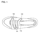
- In a prior-art belt fastening means shown in FIG. 1 of the present application, each of the
belts opening portion 110. However, in this case, thebelt 100 adapted to pull a lateral side of the upper toward a medial side and thebelt 101 adapted to pull the medial side of the upper toward the lateral side are shifted or offset in a longitudinal direction of the shoe. Thus, when each of thebelts - Japanese Patent Application Laying Open Publication No. 9-28413 shows a belt fastening means having a belt provided on one side of the upper and a D-shaped ring attached on the other side of the upper. By inserting the belt into the ring, folding back and pulling the belt, the opposite sides of the upper are nearly equally pulled and the upper is secured to a foot without twisting the upper. However, in this case, at the time of bending of a foot, D-shaped ring may interfere with a foot and hinder the movement of the foot.
- The present invention is directed to solving the above-mentioned problems, and its object is to provide a shoe with a belt fastening means that can secure an upper equally to a foot and that can advance fittability without hindering the movement of a foot.
- The present invention is directed to a belt fastening means with improved fittability for a shoe.
- In one preferred embodiment, a shoe is formed of a sole and an upper attached to the sole. The upper has a longitudinally extending opening portion formed at an instep portion thereof. The instep portion has a medial and lateral side located on opposite sides of the opening portion, and a belt fastening means provided across the opening portion in a lateral direction. The belt fastening means is comprised of first and second belt members that are disposed at generally symmetrical positions with respect to the opening portion. Each of the first and second belt members extends in a direction generally perpendicular to "a ridge line" of the instep portion as viewed from a side of the shoe. Proximal end portions of the first and second belt members are connected to the sole and distal end portions thereof extend over the opening portion. The second belt member has an elongated aperture into which the first belt member is inserted. The elongated aperture may extend along the length of the second belt member and it faces the opening portion. The first and second belt members are releasably attached to the instep portion through hook and loop fastening materials provided on the belt members.
- According to this embodiment, each of the first and second belt members extends in a direction generally orthogonal to "a ridge line" of the instep portion, or "a swell line" that extends from a position corresponding to a navicular bone of a wearer's foot to a position corresponding to a head of a metatarsus of a second or third toe, as viewed from a side of the shoe. And these belt members are disposed at symmetrical positions with respect to the opening portion. Thus, when pulling each distal end portion of the belt members in an opposite direction, the medial and lateral sides of the instep portion of the upper are equally pulled without causing torsion or wrinkles on the upper, thus securing the instep portion of the upper equally to a foot and making the whole surfaces of the belt members on the instep portion's side tightly contact with the instep portion. As a result, the whole instep of a wearer's foot can be supported in such a manner as to be wrapped by the upper of a shoe and fittability of the shoe can be improved.
- Also, since each proximal end of the first and second belt members are connected to the sole, a foot can be tightly secured to the sole through extending portions of the belt members on the medial and lateral sides of the upper when each distal end portion of the taut belt members are fastened to the instep portion of the upper.
- Moreover, in this case, not a slit but an elongated aperture extending along the length of the second belt member is formed in the second belt member and this elongated aperture faces the opening portion of the upper. Thus, insertion and extraction of the first belt member relative to the second belt member can be conducted with ease, and besides, individual differences of the height of an instep or the width of a foot can be absorbed and fittability can be maintained.
- Furthermore, in this case, since each belt member is secured to the instep portion of the upper through a hook and loop fastening material without using a metal fitting such as a D-shaped ring, the movement of a foot is not hindered and a shoe wearer does not feel uncomfortable when bending a foot.
- In another embodiment, each proximal end of the first and second belt members is connected to a sole through a reinforcement member or strip provided on the upper. In this case as well, as with the above-mentioned embodiment where each proximal end of the belt members is directly connected or fixed to a sole, when each distal end portion of the taut belt members is fastened to the instep portion, a wearer's foot can be tightly secured to the sole of a shoe through the medially and laterally extending portions of the belt members and the reinforcement members.
- In still another embodiment, the second belt member is bifurcated at a region extending from a proximal end portion to an elongated aperture and a band-shaped tab is formed integrally with a distal end portion of the second belt member. In this case, when fastening belts, insertion and extraction of the first belt member relative to the second belt member can be conducted with more ease. Also, by utilizing the tab provided at the distal end portion of the second belt member, the second belt member can be easily gripped, thereby facilitating fastening of the belts.
- In a further embodiment, a plurality of pairs of the first and second belt members are provided. In this case, a plurality of portions of the instep of a foot can be secured and fittability of a shoe can be further advanced.
- For a more complete understanding of the invention, reference should be made to the embodiments illustrated in greater detail in the accompanying drawings and described below by way of examples of the invention. In the drawings, which are not to scale:
- FIG. 1 is a top plan view of a prior art shoe.
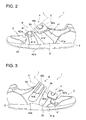
- FIG. 2 is a lateral side view of a shoe with belt members fastened according to an embodiment of the present invention.
- FIG. 3 is a medial side view of a shoe of FIG. 2.
- FIG. 4 is a top plan view of a shoe of FIG. 2.
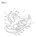
- FIG. 5 is a perspective view of a shoe of FIG. 2 with belt members unfastened.
- FIG. 6 is a lateral side view of a shoe with belt members fastened according to another embodiment of the present invention.
- FIG. 7 is a medial side view of a shoe of FIG. 6.
- FIG. 8 is a top plan view of a shoe of FIG. 6.
-
- Referring now to the drawings, FIGS. 2 to 5 illustrate a shoe according to an embodiment of the present invention. FIGS. 2 to 4 respectively show a lateral side, medial side and top side of a shoe with belts fastened. FIG. 5 shows a shoe with the belts unfastened.
- As shown in FIGS. 2 to 4, a
shoe 1 is comprised of a sole 2 and an upper 3 attached on the sole 2. An instep portion of the upper 3 located at a region corresponding to an instep of a shoe wearer's foot has anopening portion 3a extending in a longitudinal direction or along the length of the shoe. The instep portion is formed of an insteplateral side portion 31 disposed on a lateral side of theopening portion 3a and an instepmedial side portion 32 disposed on a medial side of theopening portion 3a. - There are provided at the instep portion of the upper 3 belt fastening means 4 and 4' that extend across the
opening portion 3a. In this embodiment, two pieces of belt fastening means 4 and 4' are provided. - The belt fastening means 4 is comprised of a
first belt member 41 disposed mainly on thelateral side portion 31 and asecond belt member 42 disposed mainly on themedial side portion 32. Aproximal end portion 41a of thefirst belt member 41 is connected to the sole 2 on thelateral side portion 31 and adistal end portion 41b extends over the openingportion 3a to the top portion of themedial side portion 32. Similarly, aproximal end portion 42a of thesecond belt member 42 is connected to the sole 2 on themedial side portion 32 and adistal end portion 42b extends over the openingportion 3a to the top portion of thelateral side portion 31. In this embodiment, each of theproximal end portions second belt members - As shown in FIGS. 2 and 3, the first and
second belt members second belt members - Also, the first and
second belt members opening portion 3a. That is, center lines along the lengths of thebelt members portions 3a. Thesecond belt member 42 has an elongatedaperture 42c formed therein to receive thefirst belt member 41. Theelongated aperture 42c may extend along the length of thesecond belt member 42 and it faces theopening portion 3a. In this embodiment, theelongated aperture 42c extends to theproximal end portion 42a of thesecond belt member 42. - As shown in FIG. 5, a hook and
loop fastening material 42d is attached on the back surface of thedistal end portion 42b of thesecond belt member 42. On the other hand, a corresponding hook andloop fastening material 41d is attached on thelateral side portion 31 of the upper 3 to releasably secure the hook andloop fastening material 42d of thesecond belt member 42. Similarly, a hook andloop fastening material 41e is attached on the back surface of thedistal end portion 41b of thefirst belt member 41, and a corresponding hook andloop fastening material 42e is attached on themedial side portion 32 of the upper 3 to releasably secure the hook andloop fastening material 41e of thefirst belt member 41. - The belt fastening means 4' is provided in such a manner that its first and second belt members are located opposite to the first and
second belt members medial side portion 32 of the upper 3 and that extends over the openingportion 3a, and a second belt member 42' that is disposed mainly on thelateral side portion 31 of the upper 3 and that extends over the openingportion 3a. - A proximal end portion 41'a of the first belt member 41' is fixed to the sole 2 on the
medial side portion 32, and a distal end portion 41'b extends over the openingportion 3a to the top portion of thelateral side portion 31. Similarly, a proximal end portion 42'a of the second belt member 42' is fixed to the sole 2 on thelateral side portion 31, and a distal end portion 42'b extends over the openingportion 3a to the top portion of themedial side portion 32. Additionally, the proximal end portions 41'a, 42'a of the first and second belt members 41', 42' may be connected to the sole 2 through reinforcement strips (not shown) provided on the instep portion of the upper 3. - Each of the first and second belt members 41', 42', shown in FIGS. 2 and 3, as viewed from the side of the shoe, extends in a direction nearly perpendicular to a ridge line L' of the instep portion where the belt members 41', 42' are provided. That is, each of the longitudinal center lines of the belt members 41', 42' is nearly perpendicular to the ridge line L' of the instep portion. This ridge line L', as with the above-mentioned ridge line L, generally corresponds to "the swell line" of the instep portion of a foot that extends from a position corresponding to a navicular bone of the foot to a position corresponding to a head of a metatarsus of a second or third toe of the foot.
- Also, the first and second belt members 41', 42' are located at nearly symmetrical positions relative to the
opening portion 3a. That is, longitudinal center lines of the first and second belt members 41', 42' are nearly symmetrical about theopening portion 3a. - The second belt member 42' has an elongated aperture 42'c formed therein to receive the first belt member 41'. The elongated aperture 42' c may extend along the length of the second belt member 42' and it faces the
opening portion 3a. In this embodiment, the elongated aperture 42'c extends over the proximal end portion 42'a of the second belt member 42' to the sole 2. Thus, the second belt member 42' is bifurcated at a region extending from the proximal end portion 42'a to the elongated aperture 42'c. - A hook and
loop fastening material 42'd is attached on the back surface of the distal end portion 42'b of the second belt member 42', shown in FIG. 5. On the other hand, a hook andloop fastening material 41'd is attached on themedial side portion 32 of the upper 3 to releasably secure the hook and loop fastening material 42' d of the second belt member 42'. Similarly, a hook and loop fastening material 41'e is attached on the back surface of the distal end portion 41'b of the first belt member 41', and a hook and loop fastening material 42'e is attached on thelateral side portion 31 of the upper 3 to releasably secure the hook and loop fastening material 41'e of the first belt member 41'. - According to this embodiment, as mentioned above, the
belt members lateral side portions opening portion 3a. In other words, as shown in FIG. 4, the correspondingbelt members opening portion 3a. - Thus, when each distal end portion of the corresponding belt members of the belt fastening means 4, 4' is pulled in opposite directions, moment of a couple of forces will not occur at the upper 3 and the upper 3 will not be twisted and formed with wrinkles. Thereby, the medial and
lateral side portions - Also, since each proximal end portion of the belt members is connected to the sole 2 and each distal end portion extends over the opening
portion 3a, a foot can be tightly and firmly secured to the sole 2 through medially and laterally extending portions of the belt members when each distal end portion of the belt members are pulled and fastened to the instep portion. In this case, when the proximal end portion of each belt member is formed in such a way that it widens toward the end, wider regions of the instep of a wearer's foot can be wrapped and supported. - Moreover, each of the
holes 42c, 42'c formed in thesecond belt members 42, 42' is not a slit but an elongated aperture facing theopening portion 3a of the upper 3. Thereby, insertion and extraction of thefirst belt members 41, 41' relative to thesecond belt members 42, 42' can be conducted with ease and besides, individual differences of the height of an instep or the width of a foot can be absorbed and fittability can be maintained. - Furthermore, in this case, since each belt member is secured to the instep portion of the upper through a hook and loop fastening material without using a metal fitting such as a D-shaped ring, the movement of a foot is not hindered and a shoe wearer does not feel uncomfortable when bending a foot. Additionally, in this case, shown in FIG. 5, the instep portion of the upper 3 can be fully opened by disengaging each belt fastening means 4, 4', thus facilitating ingress and egress of a foot relative to the shoe.
- FIGS. 6 to 8 illustrate a shoe according to another embodiment of the present invention. In these drawings, the same reference numerals as those in FIGS. 2 to 5 indicate the same or corresponding parts.
- The major difference from the first embodiment is that each
distal end portion 42b, 42'b of thesecond belt members 42, 42' has a tab. By providing such atab 42b, 42'b, a shoe wearer can easily grip thesecond belt members 42, 42' when fastening the belts, thereby facilitating belt fastening procedures with more ease. - In addition, each of the
proximal end portions 41a, 41'a, 42a and 42'a of the first andsecond belt members - Those skilled in the art to which the invention pertains may make modifications and other embodiments employing the principles of this invention without departing from its spirit or essential characteristics particularly upon considering the foregoing teachings. The described embodiments and examples are to be considered in all respects only as illustrative and not restrictive. The scope of the invention is, therefore, indicated by the appended claims rather than by the foregoing description. Consequently, while the invention has been described with reference to particular embodiments and examples, modifications of structure, sequence, materials and the like would be apparent to those skilled in the art, yet fall within the scope of the invention.
Claims (5)
- Shoe comprising:a sole; andan upper attached to said shoe;said upper having a longitudinally extending opening portion formed at an instep portion thereof, said instep portion having a medial side portion located on a medial side of said opening portion, a lateral side portion located on a lateral side of said opening portion, and belt fastening means provided laterally across said opening portion;said belt fastening means comprising a first belt member disposed mainly on one of said medial and lateral side portions of said upper and a second belt member disposed mainly on the other of said medial and lateral side portions of said upper, said first and second belt members being located at generally symmetrical positions with respect to said opening;said first belt member having a proximal end portion connected to said sole and a distal end portion extending over said opening portion, said first belt member extending in a direction generally perpendicular to a ridge line of said instep portion as viewed from a side of the shoe;said second belt member having a proximal end portion connected to said sole and a distal end portion extending over said opening portion, said second belt member extending in a direction generally perpendicular to said ridge line of said instep portion as viewed from the side of the shoe, said second belt member having an elongated aperture into which said first belt member is inserted, said elongated aperture facing said opening portion;said first and second belt members being releasably secured on said instep portion through hook and loop fastening materials provided on said first and second belt members.
- The shoe according to claim 1, wherein said proximal end portion of said first belt member or said second belt member is connected to said sole through a reinforcement member provided on said instep portion.
- The shoe according to claim 1, wherein said second belt member is bifurcated at a region thereof extending from said proximal end portion through said elongated aperture and said second belt member has a band-shaped tab formed integral with said distal end portion thereof.
- The shoe according to claim 1, wherein a plurality of pairs of said first and second belt members are provided.
- A shoe (1) comprising an upper portion (3) having an elongate opening (3a) for assisting a wearer to introduce a foot thereof into the shoe, and fastening means (41, 42; 41', 42'; 41b, 42b; 41'b, 42'b) for fastening lateral sides (31, 32) of the opening together, the fastening means comprising two strap members disposed opposite each other on each of said lateral sides with complimentary touch and close fastening portions (41d, 42d, 41e, 42e; 41'd, 42'd, 41'e, 42'e) so that during fastening generally equal tension is applied to said lateral sides.
Applications Claiming Priority (4)
| Application Number | Priority Date | Filing Date | Title |
|---|---|---|---|
| JP2001243621 | 2001-08-10 | ||
| JP2001243621 | 2001-08-10 | ||
| JP2002075933 | 2002-03-19 | ||
| JP2002075933A JP2003125805A (en) | 2001-08-10 | 2002-03-19 | Shoe |
Publications (3)
| Publication Number | Publication Date |
|---|---|
| EP1283018A2 true EP1283018A2 (en) | 2003-02-12 |
| EP1283018A3 EP1283018A3 (en) | 2003-03-05 |
| EP1283018B1 EP1283018B1 (en) | 2006-06-14 |
Family
ID=26620357
Family Applications (1)
| Application Number | Title | Priority Date | Filing Date |
|---|---|---|---|
| EP02252988A Expired - Fee Related EP1283018B1 (en) | 2001-08-10 | 2002-04-26 | Shoe with belt fastening means of improved fittability |
Country Status (6)
| Country | Link |
|---|---|
| US (1) | US6745500B2 (en) |
| EP (1) | EP1283018B1 (en) |
| JP (1) | JP2003125805A (en) |
| CA (1) | CA2386497C (en) |
| DE (1) | DE60212273T2 (en) |
| ES (1) | ES2265476T3 (en) |
Cited By (1)
| Publication number | Priority date | Publication date | Assignee | Title |
|---|---|---|---|---|
| US9901139B2 (en) | 2014-10-31 | 2018-02-27 | Nike, Inc. | Strap securing system, E.G., for articles of footwear and other foot-receiving devices |
Families Citing this family (11)
| Publication number | Priority date | Publication date | Assignee | Title |
|---|---|---|---|---|
| US6857204B1 (en) * | 2001-01-17 | 2005-02-22 | Reebok International Ltd. | Closure system |
| JP2005152490A (en) * | 2003-11-28 | 2005-06-16 | Asics Corp | Shoes which fit to foot with belt |
| JP2006110310A (en) * | 2004-10-18 | 2006-04-27 | Hiroshima Kasei Ltd | Shoes |
| US7500323B2 (en) * | 2005-08-15 | 2009-03-10 | Nike, Inc. | Article of footwear including a fastening system |
| JP5028053B2 (en) * | 2006-09-07 | 2012-09-19 | 徳武産業株式会社 | Footwear for people who have injury or injury on the forefoot |
| US8522455B2 (en) * | 2007-04-13 | 2013-09-03 | Nike, Inc. | Strap system with integrated eyelet |
| US8141274B2 (en) * | 2009-05-26 | 2012-03-27 | Shimano Inc. | Rowing shoe |
| US20130298426A1 (en) * | 2012-05-14 | 2013-11-14 | Elisha George Pierce | Tongueless Footwear With A Canopy |
| US9713359B2 (en) * | 2015-05-06 | 2017-07-25 | Yu Hsieh Industrial Co., Ltd. | Shoe body with arch suspended support |
| US11439201B2 (en) * | 2017-08-10 | 2022-09-13 | Nike, Inc. | Pair of asymmetrical footwear articles |
| US11497281B2 (en) * | 2019-01-28 | 2022-11-15 | TERRAIGNOTA Ventures, LLC | Securing system for footwear |
Citations (1)
| Publication number | Priority date | Publication date | Assignee | Title |
|---|---|---|---|---|
| JPH0928413A (en) | 1995-07-18 | 1997-02-04 | Asics Corp | Sports shoes |
Family Cites Families (11)
| Publication number | Priority date | Publication date | Assignee | Title |
|---|---|---|---|---|
| US770535A (en) * | 1904-09-20 | Shoe-fastener | ||
| US668408A (en) * | 1900-10-29 | 1901-02-19 | Josef Kalina | Shoe-fastener. |
| US2326776A (en) * | 1941-05-05 | 1943-08-17 | Gellman Benjamin | Shoe |
| US3845769A (en) * | 1972-10-11 | 1974-11-05 | F Shaw | Therapeutic boot |
| US4282657A (en) * | 1979-03-16 | 1981-08-11 | Antonious A J | Heel restraint with an adjustable and flexible closure assembly for shoes |
| US4486965A (en) | 1982-05-14 | 1984-12-11 | Nike, Inc. | Footwear with overlapping closure strap means |
| US5307569A (en) * | 1987-10-19 | 1994-05-03 | Melcher Jerald R | Foot support |
| JPH04367602A (en) * | 1991-06-14 | 1992-12-18 | Asahi Corp | Lacing-up part structure of string shoe |
| US5271130A (en) * | 1991-11-18 | 1993-12-21 | K-Swiss Inc. | Lacing system for shoes |
| US5699629A (en) | 1996-08-08 | 1997-12-23 | Munschy; Dorothy G. | Adjustable footwear |
| JP2000325107A (en) * | 1999-05-14 | 2000-11-28 | Nosakkusu:Kk | Belt fastening working shoes with crossing hook-and loop fastener |
-
2002
- 2002-03-19 JP JP2002075933A patent/JP2003125805A/en active Pending
- 2002-04-23 US US10/127,857 patent/US6745500B2/en not_active Expired - Fee Related
- 2002-04-26 ES ES02252988T patent/ES2265476T3/en not_active Expired - Lifetime
- 2002-04-26 EP EP02252988A patent/EP1283018B1/en not_active Expired - Fee Related
- 2002-04-26 DE DE60212273T patent/DE60212273T2/en not_active Expired - Fee Related
- 2002-05-14 CA CA2386497A patent/CA2386497C/en not_active Expired - Fee Related
Patent Citations (1)
| Publication number | Priority date | Publication date | Assignee | Title |
|---|---|---|---|---|
| JPH0928413A (en) | 1995-07-18 | 1997-02-04 | Asics Corp | Sports shoes |
Cited By (1)
| Publication number | Priority date | Publication date | Assignee | Title |
|---|---|---|---|---|
| US9901139B2 (en) | 2014-10-31 | 2018-02-27 | Nike, Inc. | Strap securing system, E.G., for articles of footwear and other foot-receiving devices |
Also Published As
| Publication number | Publication date |
|---|---|
| CA2386497A1 (en) | 2003-02-10 |
| US20030029057A1 (en) | 2003-02-13 |
| DE60212273T2 (en) | 2007-06-06 |
| DE60212273D1 (en) | 2006-07-27 |
| EP1283018B1 (en) | 2006-06-14 |
| CA2386497C (en) | 2010-01-26 |
| US6745500B2 (en) | 2004-06-08 |
| ES2265476T3 (en) | 2007-02-16 |
| EP1283018A3 (en) | 2003-03-05 |
| JP2003125805A (en) | 2003-05-07 |
Similar Documents
| Publication | Publication Date | Title |
|---|---|---|
| CA2386497C (en) | Shoe with belt fastening means of improved fittability | |
| FI89860C (en) | Sports shoes, especially off-road skiing | |
| JP3115773U (en) | Soft boots for boots and snowboards | |
| AU575077B2 (en) | Quad vamps for boots | |
| US5778500A (en) | Knot securing device | |
| US5906057A (en) | Sports boot including flexible and traction resistant return elements | |
| US20090100717A1 (en) | Boot with improved tightening of upper | |
| USRE32585E (en) | Adjustable and flexible closure assembly for shoes with variable opening | |
| US20100175278A1 (en) | Boot in particular ski or snowboard boot | |
| JPH0614801A (en) | Foot fixture for trekking shoes | |
| US7603795B2 (en) | Buckle for a sports boot and a sports boot having such buckle | |
| GB2203627A (en) | Shoes | |
| JP2000287713A (en) | Shoe tongue | |
| JP2019000213A (en) | Shoe | |
| US20130091737A1 (en) | Footwear with improved upper | |
| JPH1080305A (en) | Sports-shoe's lace with variable cross section and sport-shoe provided with lace | |
| JPH0751081B2 (en) | Ski boots | |
| JP3135943U (en) | Independent tying shoe | |
| JP4919478B2 (en) | shoes | |
| JPH0928413A (en) | Sports shoes | |
| JP3035447U (en) | Footwear | |
| US20230405440A1 (en) | Sports boot with integrated ankle compression system | |
| JPS6330242Y2 (en) | ||
| JPH01201201A (en) | Heel fixing device of ski boots | |
| JP2006314530A (en) | Shoe string loosening gear and string-type shoe |
Legal Events
| Date | Code | Title | Description |
|---|---|---|---|
| PUAI | Public reference made under article 153(3) epc to a published international application that has entered the european phase |
Free format text: ORIGINAL CODE: 0009012 |
|
| PUAL | Search report despatched |
Free format text: ORIGINAL CODE: 0009013 |
|
| AK | Designated contracting states |
Designated state(s): AT BE CH CY DE DK ES FI FR GB GR IE IT LI LU MC NL PT SE TR |
|
| AX | Request for extension of the european patent |
Extension state: AL LT LV MK RO SI |
|
| AK | Designated contracting states |
Kind code of ref document: A3 Designated state(s): AT BE CH CY DE DK ES FI FR GB GR IE IT LI LU MC NL PT SE TR |
|
| AX | Request for extension of the european patent |
Extension state: AL LT LV MK RO SI |
|
| RIC1 | Information provided on ipc code assigned before grant |
Ipc: 7A 43C 11/14 A Ipc: 7A 43B 11/00 B Ipc: 7A 43C 11/00 B |
|
| 17P | Request for examination filed |
Effective date: 20030715 |
|
| AKX | Designation fees paid |
Designated state(s): DE ES FR GB IT NL |
|
| 17Q | First examination report despatched |
Effective date: 20050303 |
|
| GRAP | Despatch of communication of intention to grant a patent |
Free format text: ORIGINAL CODE: EPIDOSNIGR1 |
|
| GRAS | Grant fee paid |
Free format text: ORIGINAL CODE: EPIDOSNIGR3 |
|
| GRAA | (expected) grant |
Free format text: ORIGINAL CODE: 0009210 |
|
| AK | Designated contracting states |
Kind code of ref document: B1 Designated state(s): DE ES FR GB IT NL |
|
| PG25 | Lapsed in a contracting state [announced via postgrant information from national office to epo] |
Ref country code: IT Free format text: LAPSE BECAUSE OF FAILURE TO SUBMIT A TRANSLATION OF THE DESCRIPTION OR TO PAY THE FEE WITHIN THE PRESCRIBED TIME-LIMIT;WARNING: LAPSES OF ITALIAN PATENTS WITH EFFECTIVE DATE BEFORE 2007 MAY HAVE OCCURRED AT ANY TIME BEFORE 2007. THE CORRECT EFFECTIVE DATE MAY BE DIFFERENT FROM THE ONE RECORDED. Effective date: 20060614 |
|
| REG | Reference to a national code |
Ref country code: GB Ref legal event code: FG4D |
|
| REF | Corresponds to: |
Ref document number: 60212273 Country of ref document: DE Date of ref document: 20060727 Kind code of ref document: P |
|
| ET | Fr: translation filed | ||
| REG | Reference to a national code |
Ref country code: ES Ref legal event code: FG2A Ref document number: 2265476 Country of ref document: ES Kind code of ref document: T3 |
|
| PLBE | No opposition filed within time limit |
Free format text: ORIGINAL CODE: 0009261 |
|
| STAA | Information on the status of an ep patent application or granted ep patent |
Free format text: STATUS: NO OPPOSITION FILED WITHIN TIME LIMIT |
|
| 26N | No opposition filed |
Effective date: 20070315 |
|
| PGFP | Annual fee paid to national office [announced via postgrant information from national office to epo] |
Ref country code: ES Payment date: 20090508 Year of fee payment: 8 |
|
| PGFP | Annual fee paid to national office [announced via postgrant information from national office to epo] |
Ref country code: DE Payment date: 20090428 Year of fee payment: 8 Ref country code: FR Payment date: 20090417 Year of fee payment: 8 Ref country code: IT Payment date: 20090421 Year of fee payment: 8 Ref country code: NL Payment date: 20090405 Year of fee payment: 8 |
|
| PGFP | Annual fee paid to national office [announced via postgrant information from national office to epo] |
Ref country code: GB Payment date: 20090422 Year of fee payment: 8 |
|
| REG | Reference to a national code |
Ref country code: NL Ref legal event code: V1 Effective date: 20101101 |
|
| GBPC | Gb: european patent ceased through non-payment of renewal fee |
Effective date: 20100426 |
|
| REG | Reference to a national code |
Ref country code: FR Ref legal event code: ST Effective date: 20101230 |
|
| PG25 | Lapsed in a contracting state [announced via postgrant information from national office to epo] |
Ref country code: FR Free format text: LAPSE BECAUSE OF NON-PAYMENT OF DUE FEES Effective date: 20100430 Ref country code: NL Free format text: LAPSE BECAUSE OF NON-PAYMENT OF DUE FEES Effective date: 20101101 |
|
| PG25 | Lapsed in a contracting state [announced via postgrant information from national office to epo] |
Ref country code: DE Free format text: LAPSE BECAUSE OF NON-PAYMENT OF DUE FEES Effective date: 20101103 |
|
| PG25 | Lapsed in a contracting state [announced via postgrant information from national office to epo] |
Ref country code: GB Free format text: LAPSE BECAUSE OF NON-PAYMENT OF DUE FEES Effective date: 20100426 Ref country code: IT Free format text: LAPSE BECAUSE OF NON-PAYMENT OF DUE FEES Effective date: 20100426 |
|
| REG | Reference to a national code |
Ref country code: ES Ref legal event code: FD2A Effective date: 20110714 |
|
| PG25 | Lapsed in a contracting state [announced via postgrant information from national office to epo] |
Ref country code: ES Free format text: LAPSE BECAUSE OF NON-PAYMENT OF DUE FEES Effective date: 20110704 |
|
| PG25 | Lapsed in a contracting state [announced via postgrant information from national office to epo] |
Ref country code: ES Free format text: LAPSE BECAUSE OF NON-PAYMENT OF DUE FEES Effective date: 20100427 |