EP1275969A1 - Circuit for detecting leakage in power supply - Google Patents
Circuit for detecting leakage in power supply Download PDFInfo
- Publication number
- EP1275969A1 EP1275969A1 EP01906139A EP01906139A EP1275969A1 EP 1275969 A1 EP1275969 A1 EP 1275969A1 EP 01906139 A EP01906139 A EP 01906139A EP 01906139 A EP01906139 A EP 01906139A EP 1275969 A1 EP1275969 A1 EP 1275969A1
- Authority
- EP
- European Patent Office
- Prior art keywords
- leakage
- resistor
- voltage
- point
- cell unit
- Prior art date
- Legal status (The legal status is an assumption and is not a legal conclusion. Google has not performed a legal analysis and makes no representation as to the accuracy of the status listed.)
- Granted
Links
Images


Classifications
-
- G—PHYSICS
- G01—MEASURING; TESTING
- G01R—MEASURING ELECTRIC VARIABLES; MEASURING MAGNETIC VARIABLES
- G01R19/00—Arrangements for measuring currents or voltages or for indicating presence or sign thereof
- G01R19/165—Indicating that current or voltage is either above or below a predetermined value or within or outside a predetermined range of values
- G01R19/16533—Indicating that current or voltage is either above or below a predetermined value or within or outside a predetermined range of values characterised by the application
- G01R19/16538—Indicating that current or voltage is either above or below a predetermined value or within or outside a predetermined range of values characterised by the application in AC or DC supplies
- G01R19/16542—Indicating that current or voltage is either above or below a predetermined value or within or outside a predetermined range of values characterised by the application in AC or DC supplies for batteries
-
- G—PHYSICS
- G01—MEASURING; TESTING
- G01R—MEASURING ELECTRIC VARIABLES; MEASURING MAGNETIC VARIABLES
- G01R31/00—Arrangements for testing electric properties; Arrangements for locating electric faults; Arrangements for electrical testing characterised by what is being tested not provided for elsewhere
- G01R31/36—Arrangements for testing, measuring or monitoring the electrical condition of accumulators or electric batteries, e.g. capacity or state of charge [SoC]
- G01R31/396—Acquisition or processing of data for testing or for monitoring individual cells or groups of cells within a battery
-
- G—PHYSICS
- G01—MEASURING; TESTING
- G01R—MEASURING ELECTRIC VARIABLES; MEASURING MAGNETIC VARIABLES
- G01R31/00—Arrangements for testing electric properties; Arrangements for locating electric faults; Arrangements for electrical testing characterised by what is being tested not provided for elsewhere
- G01R31/50—Testing of electric apparatus, lines, cables or components for short-circuits, continuity, leakage current or incorrect line connections
- G01R31/52—Testing for short-circuits, leakage current or ground faults
-
- H—ELECTRICITY
- H02—GENERATION; CONVERSION OR DISTRIBUTION OF ELECTRIC POWER
- H02J—CIRCUIT ARRANGEMENTS OR SYSTEMS FOR SUPPLYING OR DISTRIBUTING ELECTRIC POWER; SYSTEMS FOR STORING ELECTRIC ENERGY
- H02J7/00—Circuit arrangements for charging or depolarising batteries or for supplying loads from batteries
- H02J7/0013—Circuit arrangements for charging or depolarising batteries or for supplying loads from batteries acting upon several batteries simultaneously or sequentially
-
- H—ELECTRICITY
- H02—GENERATION; CONVERSION OR DISTRIBUTION OF ELECTRIC POWER
- H02J—CIRCUIT ARRANGEMENTS OR SYSTEMS FOR SUPPLYING OR DISTRIBUTING ELECTRIC POWER; SYSTEMS FOR STORING ELECTRIC ENERGY
- H02J7/00—Circuit arrangements for charging or depolarising batteries or for supplying loads from batteries
- H02J7/0047—Circuit arrangements for charging or depolarising batteries or for supplying loads from batteries with monitoring or indicating devices or circuits
-
- G—PHYSICS
- G01—MEASURING; TESTING
- G01R—MEASURING ELECTRIC VARIABLES; MEASURING MAGNETIC VARIABLES
- G01R31/00—Arrangements for testing electric properties; Arrangements for locating electric faults; Arrangements for electrical testing characterised by what is being tested not provided for elsewhere
- G01R31/40—Testing power supplies
Definitions
- the present invention relates to a leakage detection circuit for use in a power source device provided with an electric motor vehicle, and more particularly to a leakage detection circuit for use in a power source device comprising a plurality of cells.
- Electric motor vehicles are recently provided with a cell unit serving as a power source for a drive motor and generating a high voltage of at least 240 V.
- the cell unit has mounted an insulation member between the unit and a vehicle body, and is fixed to the vehicle body in a state of floating as electrically separated in order to avoid electrical shock to humans.
- the cell unit becomes high in voltage as described above, encountering the problem of electric leakage i.e., short-circuit accident between the cell and the vehicle body.
- electrolyte of the cell leaks out or, dust clinging to a surface of the cell, etc. is doused with water ingressing into the surface while the vehicle is driven in rainy weather, to impair insulation properties of the insulation member, causing such insulation fault that weak leak current flows, thereby impressing a high voltage of the cell unit on the vehicle body.
- This increases hazard including an electric shock accident caused by human contact to the vehicle body, and spark occurrence caused by large current discharging with the contact of an electrical conductive tool, etc.
- FIG. 6 It is conventional practice to detect electric leakage by providing a leakage detection circuit shown in FIG. 6.
- a leakage detection circuit With the leakage detection circuit, a pair of resistors 5, 6 are connected to opposite ends of a cell unit 1, respectively. An intermediate point between the resistors 5, 6 is grounded to the grounding (vehicle body) via a resistor 2 for detecting electric leakage.
- the cell unit 1 comprises a plurality of secondary cells such as nickel hydrogen cells which are connected to one another in series, which is likely to cause breakdown between a point of interconnecting secondary cells and the ground.
- the breakdown occurrence at such a position entails a problem of creating a dead zone wherein the leakage cannot be detected, or of reducing detection sensitivity as will be described below.
- a resistor 4 corresponds to breakdown occurrence at an intermediate point of the cell unit 1.
- Current flows through a leakage detection resistor 2 by way of 2 routes as indicated by an arrow in a solid line and by an arrow in a broken line.
- the currents i1 and i2 flow in opposite directions each other, as described above, so that a voltage V1 detected becomes a smaller value, making sensitivity reduced, making it difficult to detect the voltage. Furthermore, when a voltage (+B) of the cell unit 1 varies, the voltage changes a detection value of leakage, whereby entailing a problem that the leakage cannot be detected with high accuracy.
- An object of the present invention is to provide a leakage detection circuit for use in a power source device comprising a cell unit of high voltage, which circuit is adapted to detect reliably with a simple structure leakage occurrence in a cell unit, and which is adapted to presume a portion of leakage.
- a leakage detection circuit for use in a power source device embodying the present invention comprises:
- the leakage detection circuit of the invention described suppose the leakage occurs at any point of connection between the plurality of cells constituting the cell unit. There is no change in current flowing through the first current path, and the reference voltage generated at the reference point is constant. On the other hand, in the second current path, leaking current flows from the intermediate point through the insulation resistor to the grounding (vehicle body), generating change in potential of the two points divided by the intermediate point, whereby outputs of the first and the second comparators are changed. As a result, the leakage occurrence is detected.
- a circuit constant of the first and the second current paths is so adjusted that in the event of leakage occurrence at any point of connection between the cells constituting the cell unit, a dead zone in detecting leakage based on the outputs given by the first and the second comparators is contained in an inside of potential distribution region corresponding to one cell, which is included in potential distribution generated between opposite electrodes of the cell unit.
- a leakage detection circuit for use in a power source unit of the invention comprises:
- the leakage occurrence can be detected reliably since the reference voltage is fixed.
- the first and the second comparators each outputs two signals different in potential corresponding to magnitude relation between a voltage impressed to one input end and a reference voltage impressed to the other input end.
- the first comparator outputs a signal "high” when the voltage to be impressed to the one input end is greater than the voltage to be impressed to the other input end.
- the second comparator outputs a signal "high” when the voltage to be impressed to the one input end is smaller than the voltage to be impressed to the other input end.
- the detection circuit comprises a photocoupler which is connected to an output end of the first comparator and to an output end of the second comparator.
- the photocoupler comprises a light-emitting diode for emitting light corresponding to potentials of the output ends, and a phototransistor to be turned on by light-emitting of the light-emitting diode, and detects leakage occurrence based on on/off of the phototransistor.
- values of resistance for the first and the second voltage dividing resistors interposed on the first current line, for the first and the second protection resistors interposed on the second current line, and for the first and the second detection resistors interposed on the second current line are so adjusted that in the event of the leakage occurrence at any point of connection between the plurality of cells constituting the cell unit, the dead zone in detecting leakage, wherein a voltage to be impressed to the one input end of the first comparator is greater than a reference voltage to be impressed to the other input end, and a voltage to be impressed to one input end of the second comparator is smaller than a reference voltage to be impressed to the other input end, is contained in an inside of a potential distribution region corresponding to one cell, which is included in potential distribution generated between opposite electrodes of the cell unit.
- the leakage detection circuit for use in the power source device embodying the invention as described above, the leakage occurrence at the point of connection between a plurality of cells comprising the cell unit can be reliably detected. This can forestall electric shock accidents.
- two cell modules 12A, 12B comprises a plurality of secondary cells 12a, which are connected in series.
- the two cell modules 12A, 12B constitute a cell unit 12 which is mounted on a vehicle body through an insulation member.
- Nickel hydrogen cells, etc. are used as secondary cells 12a. Obtained between a positive terminal and a negative terminal of the cell unit 12 is, for example, 300V, in total voltage.
- a positive-side power line 10a and a negative-side power line 10b extend, respectively, from a positive and a negative terminals of the cell unit 12, and are connected to an inverter which is not shown.
- the inverter comprises a switching element such as IGBT (Insulated Gate Bipolar Transistor), etc. and converts d.c. power to a.c. power to supply the power to a drive motor.
- IGBT Insulated Gate Bipolar Transistor
- the leakage detection circuit 10 of the invention comprises a first current line 34 and a second current line 22 which are connected to each other in parallel between the positive-side power line 10a and the negative-side power line 10b.
- a first current line 34 Interposed on the first current line 34 are a first voltage dividing resistor 30 and a second voltage dividing resistor 32 each having a value of resistance of 56k ⁇ , which are related each other in parallel.
- a first protection resistor 14 and a second protection resistor 16 each having a high value of resistance of 1M ⁇ , which are related each other in parallel.
- Interposed between the two protection resistors 14, 16 are a first detection resistor 18 and a second detection resistor 20 each having a value of resistance of 22k ⁇ , which are related each other in parallel.
- a point of connection 24 between the first and the second detection resistors 18, 20 which are interposed on the second current line 22 is connected to a ground (vehicle body) through an insulation resistor 28 having a high value of resistance of 6M ⁇ .
- the leakage detection circuit of the invention comprises a first Op-Amp 36 and a second Op-Amp 38.
- a point of connection 35 (reference point) between the first voltage dividing resistor 30 and the second voltage dividing resistor 32 which is interposed on the first current line 34 is connected to a negative input terminal of the first Op-Amp 36 through a current limiting resistor 44 having a value of resistance of 100k ⁇ , and is connected to a positive terminal of the second Op-Amp 38 through a current limiting resistor 46 having a value of resistance of 100k ⁇ .
- a point of connection P1 between the first protection resistor 14 and the first detection resistor 18 which are interposed on the second current line 22 is connected to a positive input terminal of the first Op-Amp 36 through a current limiting resistor 42 having a value of resistance of 100k ⁇ .
- a point of connection P2 between the second protection resistor 16 and the second detection resistor 20 is connected to a negative input terminal of the second Op-Amp 38 through a current limiting resistor 48 having a value of resistance of 100k ⁇ .
- Op-Amps 36, 38 are given defined power source voltages, +15V, -15V, respectively, as illustrated.
- the leakage detection circuit of the present invention comprises a photocoupler 40 having a light-emitting diode 50 and a phototransistor 52.
- An output end of the first Op-Amp 3.6 and that of the second Op-Amp 38 are interconnected to, respectively, via resistors 54, 56, and a point of the interconnection is connected to the light-emitting diode 50.
- the leakage occurrence causes the light-emitting diode to emit light, as will be described below, to have the phototransistor 52 electrically conducted, notifying the leakage occurrence to a microcomputer not shown.
- the cell unit 12 of high voltage is insulated from the grounding (vehicle body) 26 by an insulation resistor 28 to be in a floating state, so that leakage current does not flow through the first and the second detection resistors, 18, 20 of the second current line 22. Accordingly, the leakage voltage will not be generated between opposite ends of any of the detection resistors 18, 20.
- the negative-side power line 10b extending from a negative terminal of the cell unit 12 is grounded to the grounding 26(vehicle) via the ground resistor 58, as shown in FIG. 1.
- the leakage current flows through the first and second protection resistors 14, 16, the first detection and second detection resistors 18, 20, the insulation resistor 28, and the ground resistor 58, via the grounding 26, generating a voltage V1 and a voltage V2 resulted from the leakage between opposite ends of each of the first and second detection resistors 18, 20.
- Voltage differences V1IN and V2IN between each of the voltages V1, V2 and a reference voltage Vc impressed from the reference point 35 of the first current line 34 are respectively input to the first and second Op-Amps 36, 38.
- the voltage differences are compared with the predetermined values, respectively, in the Op-Amps 36, 38.
- the Op-Amps 36, 38 each produce output voltages V1OUT and V2OUT.
- the negative terminal of the cell unit 12 is grounded by fault via the ground resistor 58 having a resistance value of 100k ⁇ , and a leakage current ig flows, forming an equivalent circuit shown in FIG. 5.
- i is a circuit current.
- the microcomputer detects that a signal from the phototransistor 52 is changed over from high to low, thereby determinig the leakage occurrence.
- power lines extend from the positive and negative terminals of the cell unit 12, respectively, as shown in FIG.2, and voltage detection lines extend from points of connection between cells 12a, and lines further extend from points of connection between the cell modules 12A and 12B to a safety switch, so that if any line of the lines described above is grounded by fault, the leakage occurs. There is a possibility of the leakage occurrence at each point indicated by cross marks shown in FIG. 2.
- Input voltages V1IN and V2IN shown in FIG. 1 are found as for each point wherein there is a possibility of the leakage occurrence, and the result found is given as follows.
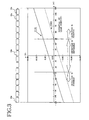
- FIG. 3 is a graph showing input voltage V1IN and V2IN, respectively, in a solid line and in a broken line when the leakage occurs at each point, wherein a potential at each point of leakage occurrence is plotted as the X-axis and a potential of input voltage V1IN and V2IN is plotted as the Y-axis in the case where the ground resistor 58 is 100k ⁇ .
- FIG. 3 shows that the following three cases are present depending on a point of leakage occurrence: 1 ⁇ V1IN>0, V2IN ⁇ 0, 2 ⁇ V1IN ⁇ 0, V2IN ⁇ 0, 3 ⁇ V1IN>0, V2IN>0.
- the photocoupler is turned on to permit the leakage detection, while in the case of 1 ⁇ the photocoupler is not turned on, and thereby the leakage cannot be detected. That is, with the leakage detection circuit 10 having the circuit constant described above, the leakage cannot be detected at points of leakage within ⁇ 45V shown in FIG. 3, whereby generating a dead zone.
- Table 1 shows the result of calculating the input voltage V1IN and V2IN at representative points ( ⁇ 120V, ⁇ 90V, ⁇ 30V, 0V) out of the points (1), (2), and (3) each having a possibility of the leakage occurrence as described above. leak.
- both of the input voltage V1In and V2In at the point of the leakage occurrence should be made positive or negative.
- the conditions for this are as follows:
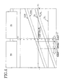
- FIG. 2 shows the result obtained by altering the circuit constant so as to fulfill the above conditions.
- FIG. 4 shows a graph in the same manner as FIG. 3 in the case where the ground resistor 58 is 100k ⁇ with the leakage detection circuit 10 after the alteration of the circuit constant.
- Table 3 further shows the result obtained by calculating the input voltage V1In and V2IN after the alteration of the circuit constant at each point of leakage occurrence. leak.
- the leakage can be detected as for any point wherein there is a possibility of leakage occurrence by altering the circuit constant, i.e. by suitably adjusting the ratio of the protection resistor to the detection resistor (value of the leakage detection voltage Va and that of Vb) and the ratio of the voltage dividing resistor (value of the reference voltage Vc).
- the point wherein there is a possibility of the leakage occurrence can be identified in advance, so that the leakage can be detected at each point by setting each value of the protection, detection, and voltage dividing resistors so as to shift the dead zone of the leakage detection from the leakage point.
Abstract
Description
- The present invention relates to a leakage detection circuit for use in a power source device provided with an electric motor vehicle, and more particularly to a leakage detection circuit for use in a power source device comprising a plurality of cells.
- Electric motor vehicles are recently provided with a cell unit serving as a power source for a drive motor and generating a high voltage of at least 240 V. The cell unit has mounted an insulation member between the unit and a vehicle body, and is fixed to the vehicle body in a state of floating as electrically separated in order to avoid electrical shock to humans. The cell unit becomes high in voltage as described above, encountering the problem of electric leakage i.e., short-circuit accident between the cell and the vehicle body.
- For example, electrolyte of the cell leaks out or, dust clinging to a surface of the cell, etc. is doused with water ingressing into the surface while the vehicle is driven in rainy weather, to impair insulation properties of the insulation member, causing such insulation fault that weak leak current flows, thereby impressing a high voltage of the cell unit on the vehicle body. This increases hazard including an electric shock accident caused by human contact to the vehicle body, and spark occurrence caused by large current discharging with the contact of an electrical conductive tool, etc.
- It is conventional practice to detect electric leakage by providing a leakage detection circuit shown in FIG. 6. With the leakage detection circuit, a pair of
resistors cell unit 1, respectively. An intermediate point between theresistors resistor 2 for detecting electric leakage. - The
cell unit 1 comprises a plurality of secondary cells such as nickel hydrogen cells which are connected to one another in series, which is likely to cause breakdown between a point of interconnecting secondary cells and the ground. The breakdown occurrence at such a position entails a problem of creating a dead zone wherein the leakage cannot be detected, or of reducing detection sensitivity as will be described below. - As shown in FIG. 6, a
resistor 4 corresponds to breakdown occurrence at an intermediate point of thecell unit 1. Current flows through aleakage detection resistor 2 by way of 2 routes as indicated by an arrow in a solid line and by an arrow in a broken line. Suppose when the currents are i1, i2 as illustrated, the currents are expressed as follows: - In the case where a value of resistance R1 for the
resistor 5 is equal to a value of resistance R2 for theresistor 6, the two currents, i1 and i2 are equal in amount and are opposite in flowing direction, so that a voltage V1 detected is zero in spite of electric leakage occurrence. Even if a value of resistance for theresistor 5 is different from a value for theresistor 6, the dead zone will be created when leakage occurs at any point of connection between a plurality of cells constituting thecell unit 1. - In this case, the currents i1 and i2 flow in opposite directions each other, as described above, so that a voltage V1 detected becomes a smaller value, making sensitivity reduced, making it difficult to detect the voltage. Furthermore, when a voltage (+B) of the
cell unit 1 varies, the voltage changes a detection value of leakage, whereby entailing a problem that the leakage cannot be detected with high accuracy. - An object of the present invention is to provide a leakage detection circuit for use in a power source device comprising a cell unit of high voltage, which circuit is adapted to detect reliably with a simple structure leakage occurrence in a cell unit, and which is adapted to presume a portion of leakage.
- A leakage detection circuit for use in a power source device embodying the present invention comprises:
- a first current path being connected to opposite electrodes of the cell unit comprising a plurality of cells, and having a reference point generating a reference voltage corresponding to potential difference between the opposite electrodes,
- a second current path being connected to the opposite electrodes of the cell unit, and having three points which are different in potential difference, the three points of which an intermediate point is connected to a grounding via an insulation resistor,
- a first and second comparators having one input end to which voltage is applied from each of the two points divided by the intermediate point of the second current path, and having the other input end to which reference voltage is applied from the reference point of the first current path, and
- a detection circuit detecting leakage occurrence based on outputs of the first and the second comparators.
-
- With the leakage detection circuit of the invention described, suppose the leakage occurs at any point of connection between the plurality of cells constituting the cell unit. There is no change in current flowing through the first current path, and the reference voltage generated at the reference point is constant. On the other hand, in the second current path, leaking current flows from the intermediate point through the insulation resistor to the grounding (vehicle body), generating change in potential of the two points divided by the intermediate point, whereby outputs of the first and the second comparators are changed. As a result, the leakage occurrence is detected.
- Accordingly, even if leakage voltage varies along with magnitude of leakage current, the leakage can be detected reliably since the reference voltage is fixed.
- Stated specifically, a circuit constant of the first and the second current paths is so adjusted that in the event of leakage occurrence at any point of connection between the cells constituting the cell unit, a dead zone in detecting leakage based on the outputs given by the first and the second comparators is contained in an inside of potential distribution region corresponding to one cell, which is included in potential distribution generated between opposite electrodes of the cell unit.
- This eliminates the problem of the dead zone in the leakage detection.
- A leakage detection circuit for use in a power source unit of the invention comprises:
- a first current line having opposite ends connected to opposite electrodes, respectively, of the cell unit, and having connected in series each other first and second voltage dividing resistors, and having the resistors interposed between the opposite ends,
- a second current line having opposite ends connected to opposite electrodes, respectively, of the cell unit, and having connected in series sequentially a first protection resistor, a first detection resistor, a second detection resistor, and a second protection resistor, and having the resistors interposed between the opposite ends,
- a grounding connection line connecting to a grounding via an insulation resistor a point of connection between the first detection resistor and the second detection resistor which are interposed on the second current line,
- a first comparator having one input end connected to a point of connection between the first protection resistor and the first detection resistor which are interposed on the second current line, and having the other input end connected to a point of connection between the first voltage dividing resistor and the second voltage dividing resistor which are interposed on the first current line,
- a second comparator having one input end connected to a point of connection between the second detection resistor and the second protection resistor which are interposed on the second current line, and having the other input end connected to a point of connection between the first voltage dividing resistor and the second voltage dividing resistor which are interposed on the first current line, and
- a detection circuit detecting leakage occurrence based on outputs of the first and the second comparators.
-
- With the leakage detection circuit of the invention described, suppose the leakage occurs at any point of connection between the plurality of cells constituting the cell unit. There is no change in current flowing through the first current line, and a reference voltage generated at a point of connection (reference point) between the first and the second voltage dividing resistors is therefore constant. On the other hand, in the second current line, leaking current flows from a point of connection (intermediate point) between the first and the second detection resistors through the grounding connection line and the insulation resistor to the grounding (vehicle body), generating change corresponding to the magnitude of the leakage current in potentials of a point of connection between the first protection resistor and the first detection resistor and in potentials of a point of connection between the second detection resistor and the second protection resistor, whereby outputs of the first and the second comparators are changed. As a result, the leakage occurrence is detected.
- Accordingly, even if a leakage voltage varies along with the magnitude of the leakage current, the leakage occurrence can be detected reliably since the reference voltage is fixed.
- Stated specifically, the first and the second comparators each outputs two signals different in potential corresponding to magnitude relation between a voltage impressed to one input end and a reference voltage impressed to the other input end. For example, the first comparator outputs a signal "high" when the voltage to be impressed to the one input end is greater than the voltage to be impressed to the other input end. The second comparator outputs a signal "high" when the voltage to be impressed to the one input end is smaller than the voltage to be impressed to the other input end.
- Stated further specifically, the detection circuit comprises a photocoupler which is connected to an output end of the first comparator and to an output end of the second comparator. The photocoupler comprises a light-emitting diode for emitting light corresponding to potentials of the output ends, and a phototransistor to be turned on by light-emitting of the light-emitting diode, and detects leakage occurrence based on on/off of the phototransistor.
- Stated furthermore specifically, values of resistance for the first and the second voltage dividing resistors interposed on the first current line, for the first and the second protection resistors interposed on the second current line, and for the first and the second detection resistors interposed on the second current line are so adjusted that in the event of the leakage occurrence at any point of connection between the plurality of cells constituting the cell unit, the dead zone in detecting leakage, wherein a voltage to be impressed to the one input end of the first comparator is greater than a reference voltage to be impressed to the other input end, and a voltage to be impressed to one input end of the second comparator is smaller than a reference voltage to be impressed to the other input end, is contained in an inside of a potential distribution region corresponding to one cell, which is included in potential distribution generated between opposite electrodes of the cell unit.
- Consequently, even in the event of the leakage occurrence at any point of connection between the plurality of cells comprising the cell unit, the potential at the point of the leakage occurrence does not correspond to the dead zone.
- The leakage detection circuit for use in the power source device embodying the invention, as described above, the leakage occurrence at the point of connection between a plurality of cells comprising the cell unit can be reliably detected. This can forestall electric shock accidents.
-
- FIG. 1 is an example construction of a leakage detection circuit embodying the invention;
- FIG. 2 is a diagram for indicating a point having a possibility of leakage occurrence in a cell unit;
- FIG. 3 is a graph showing a. relationship between a potential of leakage occurrence and an input voltage to two Op-Amps;
- FIG. 4 is a graph showing an example for eliminating the problem of a dead zone by altering a circuit constant as in the same manner as FIG. 3;
- FIG. 5 is a diagram showing an equivalent circuit which is part of a circuit shown in FIG. 1 and a circuit constant; and
- FIG. 6 is a circuit diagram showing the construction of a conventional leakage detection circuit.
-
- With reference to the drawings, a detailed description will be given of a leakage detection circuit embodying the invention for use in a power source unit, which is mounted on an electric motor vehicle.
- As shown in FIG. 1, two
cell modules secondary cells 12a, which are connected in series. The twocell modules cell unit 12 which is mounted on a vehicle body through an insulation member. Nickel hydrogen cells, etc. are used assecondary cells 12a. Obtained between a positive terminal and a negative terminal of thecell unit 12 is, for example, 300V, in total voltage. - A positive-
side power line 10a and a negative-side power line 10b extend, respectively, from a positive and a negative terminals of thecell unit 12, and are connected to an inverter which is not shown. The inverter comprises a switching element such as IGBT (Insulated Gate Bipolar Transistor), etc. and converts d.c. power to a.c. power to supply the power to a drive motor. - The
leakage detection circuit 10 of the invention comprises a firstcurrent line 34 and a secondcurrent line 22 which are connected to each other in parallel between the positive-side power line 10a and the negative-side power line 10b. Interposed on the firstcurrent line 34 are a firstvoltage dividing resistor 30 and a secondvoltage dividing resistor 32 each having a value of resistance of 56kΩ, which are related each other in parallel. Interposed on the secondcurrent line 22 are afirst protection resistor 14 and asecond protection resistor 16 each having a high value of resistance of 1MΩ, which are related each other in parallel. Interposed between the twoprotection resistors first detection resistor 18 and asecond detection resistor 20 each having a value of resistance of 22kΩ, which are related each other in parallel. - A point of
connection 24 between the first and thesecond detection resistors current line 22 is connected to a ground (vehicle body) through aninsulation resistor 28 having a high value of resistance of 6MΩ. - The leakage detection circuit of the invention comprises a first Op-
Amp 36 and a second Op-Amp 38. A point of connection 35 (reference point) between the firstvoltage dividing resistor 30 and the secondvoltage dividing resistor 32 which is interposed on the firstcurrent line 34 is connected to a negative input terminal of the first Op-Amp 36 through a current limitingresistor 44 having a value of resistance of 100kΩ, and is connected to a positive terminal of the second Op-Amp 38 through a current limitingresistor 46 having a value of resistance of 100kΩ. A point of connection P1 between thefirst protection resistor 14 and thefirst detection resistor 18 which are interposed on the secondcurrent line 22 is connected to a positive input terminal of the first Op-Amp 36 through a current limitingresistor 42 having a value of resistance of 100kΩ. A point of connection P2 between thesecond protection resistor 16 and thesecond detection resistor 20 is connected to a negative input terminal of the second Op-Amp 38 through a current limitingresistor 48 having a value of resistance of 100kΩ. - Op-
Amps - The leakage detection circuit of the present invention comprises a
photocoupler 40 having a light-emittingdiode 50 and aphototransistor 52. An output end of the first Op-Amp 3.6 and that of the second Op-Amp 38 are interconnected to, respectively, viaresistors diode 50. The leakage occurrence causes the light-emitting diode to emit light, as will be described below, to have thephototransistor 52 electrically conducted, notifying the leakage occurrence to a microcomputer not shown. - When the leakage does not occur, the
cell unit 12 of high voltage is insulated from the grounding (vehicle body) 26 by aninsulation resistor 28 to be in a floating state, so that leakage current does not flow through the first and the second detection resistors, 18, 20 of the secondcurrent line 22. Accordingly, the leakage voltage will not be generated between opposite ends of any of thedetection resistors - For example, suppose a negative terminal of the
cell unit 12 is grounded by fault via aground resistor 58 having a resistance value of 100kΩ, as shown in FIG. 1, causing leakage occurrence. In this case, the negative-side power line 10b extending from a negative terminal of thecell unit 12 is grounded to the grounding 26(vehicle) via theground resistor 58, as shown in FIG. 1. Accordingly, the leakage current flows through the first andsecond protection resistors second detection resistors insulation resistor 28, and theground resistor 58, via thegrounding 26, generating a voltage V1 and a voltage V2 resulted from the leakage between opposite ends of each of the first andsecond detection resistors - Voltage differences V1IN and V2IN between each of the voltages V1, V2 and a reference voltage Vc impressed from the
reference point 35 of the firstcurrent line 34 are respectively input to the first and second Op-Amps Amps Amps - In the example shown in FIG. 1, the negative terminal of the
cell unit 12 is grounded by fault via theground resistor 58 having a resistance value of 100kΩ, and a leakage current ig flows, forming an equivalent circuit shown in FIG. 5. With the equivalent circuit, a following relationship is obtained, wherein i is a circuit current. - Accordingly, V1OUT=-15V and V2OUT=+15V, with the result that the light-emitting
diode 50 of thephotocoupler 40 emits light to have thephototransistor 52 turned on. The microcomputer detects that a signal from thephototransistor 52 is changed over from high to low, thereby determinig the leakage occurrence. - Furthermore, in the case where the leakage occurs at a positive terminal side of the
cell unit 12, the same result as described is obtained. - When the leakage does not occur, only the circuit current i is generated, V1IN=3.23V, V2IN=-3.23V, V1OUT=+15V, and V2OUT=+15V, to have the
photocoupler 40 held off. - With the
cell unit 12, power lines extend from the positive and negative terminals of thecell unit 12, respectively, as shown in FIG.2, and voltage detection lines extend from points of connection betweencells 12a, and lines further extend from points of connection between thecell modules - Input voltages V1IN and V2IN shown in FIG. 1 are found as for each point wherein there is a possibility of the leakage occurrence, and the result found is given as follows. In this case, the
cell unit 12 comprises 16 cells, and the unit has an output voltage of 240V(=15V × 16). - (1) power line(±)/ d.c. side of inverter(±) ±120V
- (2) voltage detection line of cell module ±15V×8 points
- (3) safety switch line 0V
-
- FIG. 3 is a graph showing input voltage V1IN and V2IN, respectively, in a solid line and in a broken line when the leakage occurs at each point, wherein a potential at each point of leakage occurrence is plotted as the X-axis and a potential of input voltage V1IN and V2IN is plotted as the Y-axis in the case where the
ground resistor 58 is 100kΩ. - FIG. 3 shows that the following three cases are present depending on a point of leakage occurrence: 1 ○ V1IN>0, V2IN<0, 2 ○ V1IN<0, V2IN<0, 3 ○ V1IN>0, V2IN>0. In the cases of 2 ○ and 3 ○ the photocoupler is turned on to permit the leakage detection, while in the case of 1 ○ the photocoupler is not turned on, and thereby the leakage cannot be detected. That is, with the
leakage detection circuit 10 having the circuit constant described above, the leakage cannot be detected at points of leakage within ±45V shown in FIG. 3, whereby generating a dead zone. - In this embodiment the influence of the dead zone is avoided by adjusting the circuit constant of the
leakage detection circuit 10, as will be described below. - Table 1 shows the result of calculating the input voltage V1IN and V2IN at representative points (±120V, ± 90V, ±30V, 0V) out of the points (1), (2), and (3) each having a possibility of the leakage occurrence as described above.
leak. Resist. -120V -90V -30V 0V 30V 90V 120V V1IN short circuit -6.63 -4.33 0.28 2.58 4.89 9.49 11.8 V2IN -11.8 -9.49 -4.89 -2.58 -0.28 4.33 6.63 V1IN 100k -6.49 -4.22 0.31 2.58 4.85 9.39 11.66 V2IN -11.66 -9.39 -4.85 -2.58 -0.31 4.22 6.49 - In order to permit the leakage detection at any point wherein there is a possibility of the leakage occurrence, both of the input voltage V1In and V2In at the point of the leakage occurrence should be made positive or negative. The conditions for this are as follows:
- (1) X-intercept of the input voltage V1IN and V2IN shown in FIG. 3 is in the range of 0 to 15V or 0 to -15V.
- (2) the intersection of a solid line showing variation of the leakage detection voltage Va (potential of P1 in FIG. 1), Vb (potential of P2 in FIG.1) and the reference potential Vc is in the range of 0 to 15V or 0 to -15V.
-
- FIG. 2 shows the result obtained by altering the circuit constant so as to fulfill the above conditions.
R1(k) R2(k) R3(k) R4(k) RC1(k) RC2(k) ZDC1 ZDC2 Before alter. 1000 22 22 1000 56 56 15V 15V After alter. 3450 10 10 3300 58.5 56 15V 15V - Furthermore, FIG. 4 shows a graph in the same manner as FIG. 3 in the case where the
ground resistor 58 is 100kΩ with theleakage detection circuit 10 after the alteration of the circuit constant. - Table 3 further shows the result obtained by calculating the input voltage V1In and V2IN after the alteration of the circuit constant at each point of leakage occurrence.
leak. Resist. -120V -90V -30V 0V 30V 90V 120V V1IN short -25.42 -18.84 -5.68 0.9 7.48 20.64 27.21 (Va) circuit (-28.04) (-21.46) (-8.3) (-1.72) (4.86) (18.02) (24.59) V2IN -26.12 -19.54 -6.39 0.19 6.77 19.92 26.5 (Vb) (-28.74) (-22.16) (-9.01) (-2.43) (4.15) (17.3) (23.88) V1IN 100k -25.09 -18.59 -5.6 0.89 7.39 20.37 26.87 (Va) (-27.71) (-21.21) (-8.22) (-1.73) (4.77) (17.75) (24.25) V2IN -25.79 -19.3 -6.31 0.18 6.68 19.66 26.16 (Vb) (-28.41) (21.92) (-8.93) (-2.44) (4.06) (17.04) (23.54) - According to the above calculation results, it is found that the leakage can be detected as for any point wherein there is a possibility of leakage occurrence by altering the circuit constant, i.e. by suitably adjusting the ratio of the protection resistor to the detection resistor (value of the leakage detection voltage Va and that of Vb) and the ratio of the voltage dividing resistor (value of the reference voltage Vc).
- With the
leakage detection circuit 10 shown in FIG. 1, the point wherein there is a possibility of the leakage occurrence can be identified in advance, so that the leakage can be detected at each point by setting each value of the protection, detection, and voltage dividing resistors so as to shift the dead zone of the leakage detection from the leakage point.
Claims (8)
- A leakage detection circuit for use in a power source device provided with a cell unit comprising a plurality of cells, the leakage detection circuit for use in the power source device being characterized in that the circuit comprises:a first current path being connected to opposite electrodes of the cell unit, and having a reference point generating a reference voltage corresponding to potential difference between the opposite electrodes,a second current path being connected to the opposite electrodes of the cell unit, and having three points which are different in potential difference, the three points of which an intermediate point is connected to a grounding via an insulation resistor,a first and second comparators having one input end to which voltage is applied from each of the two points divided by the intermediate point of the second current path, and having the other input end to which reference voltage is applied from the reference point of the first current path, anda detection circuit detecting leakage occurrence based on outputs of the first and the second comparators.
- A leakage detection circuit for use in a power source device according to claim 1 wherein a circuit constant of the first and the second current paths is so adjusted that in the event of leakage occurrence at any point of connection between the cells constituting the cell unit, a dead zone in detecting leakage based on the outputs given by the first and the second comparators is contained in an inside of potential distribution region corresponding to one cell, which is included in potential distribution generated between opposite electrodes of the cell unit.
- A leakage detection circuit for use in a power source unit provided with a cell unit comprising a plurality of cells, the leakage detection circuit for use in the power source device being characterized in that the circuit comprises:a first current line having opposite ends connected to opposite electrodes, respectively, of the cell unit, and having first and second voltage dividing resistors connected in series each other, and having the resistors interposed between the opposite ends,a second current line having opposite ends connected to opposite electrodes, respectively, of the cell unit, and having connected in series sequentially a first protection resistor, a first detection resistor, a second detection resistor, and a second protection resistor, and having the resistors interposed between the opposite ends,a grounding connection line connecting to a grounding via an insulation resistor a point of connection between the first detection resistor and the second detection resistor which are interposed on the second current line,a first comparator having one input end connected to a point of connection between the first protection resistor and the first detection resistor which are interposed on the second current line, and having the other input end connected to a point of connection between the first voltage dividing resistor and the second voltage dividing resistor which are interposed on the first current line,a second comparator having one input end connected to a point of connection between the second detection resistor and the second protection resistor which are interposed on the second current line, and having the other input end connected to a point of connection between the first voltage dividing resistor and the second voltage dividing resistor which are interposed on the first current line, anda detection circuit detecting leakage occurrence based on outputs of the first and the second comparators.
- A leakage detection circuit for use in a power source device according to claim 3 wherein the first and the second comparators each outputs two signals different in potential corresponding to magnitude relation between a voltage impressed to one input end and a reference voltage impressed to the other input end.
- A leakage detection circuit for use in a power source device according to claim 3 or claim 4 wherein the circuit comprises a photocoupler which is connected to an output end of the first comparator and to an output end of the second comparator, and which comprises a light-emitting diode for emitting light corresponding to potentials of the output ends and a phototransistor to be turned on by light-emitting of the light-emitting diode, and the circuit detects leakage occurrence based on on/off of the phototransistor.
- A leakage detection circuit for use in a power source device according to any one of claims 3 to 5 wherein a dead zone in detecting leakage is generated when a voltage to be impressed to one input end of the first comparator is greater than a reference voltage to be impressed to the other input end, and when a voltage to be impressed to one input end of the second comparator is smaller than a reference voltage to be impressed to the other input end.
- A leakage detection circuit for use in a power source device according to any one of claims 3 to 6 wherein in the event of the leakage occurrence at any point of connection between the plurality of cells constituting the cell unit, the dead zone in detecting leakage based on the outputs of the first and the second comparators is contained in an inside of a potential distribution region corresponding to one cell, which is included in potential distribution generated between the opposite electrodes of the cell unit.
- A leakage detection circuit for use in a power source device according to claim 7 wherein values of resistance for the first and the second voltage dividing resistors which are interposed on the first current line, for the first and the second protection resistors, and for the first and the second detection resistors which are interposed on the second current line are so adjusted as to serve as a circuit constant of the first and the second current line.
Applications Claiming Priority (3)
| Application Number | Priority Date | Filing Date | Title |
|---|---|---|---|
| JP2000043798 | 2000-02-22 | ||
| JP2000043798 | 2000-02-22 | ||
| PCT/JP2001/001201 WO2001063306A1 (en) | 2000-02-22 | 2001-02-20 | Circuit for detecting leakage in power supply |
Publications (3)
| Publication Number | Publication Date |
|---|---|
| EP1275969A1 true EP1275969A1 (en) | 2003-01-15 |
| EP1275969A4 EP1275969A4 (en) | 2005-01-19 |
| EP1275969B1 EP1275969B1 (en) | 2006-04-12 |
Family
ID=18566657
Family Applications (1)
| Application Number | Title | Priority Date | Filing Date |
|---|---|---|---|
| EP01906139A Expired - Lifetime EP1275969B1 (en) | 2000-02-22 | 2001-02-20 | Circuit for detecting leakage in power supply |
Country Status (7)
| Country | Link |
|---|---|
| US (1) | US6700384B2 (en) |
| EP (1) | EP1275969B1 (en) |
| JP (1) | JP3600211B2 (en) |
| KR (1) | KR20030010582A (en) |
| CN (1) | CN1214251C (en) |
| DE (1) | DE60118718T2 (en) |
| WO (1) | WO2001063306A1 (en) |
Cited By (6)
| Publication number | Priority date | Publication date | Assignee | Title |
|---|---|---|---|---|
| SG110000A1 (en) * | 2001-11-21 | 2005-04-28 | Seiko Instr Inc | Battery voltage detecting circuit |
| EP2105753A1 (en) * | 2008-03-27 | 2009-09-30 | Hitachi Ltd. | Assembled battery total voltage detection circuit |
| EP2508904A1 (en) * | 2009-12-03 | 2012-10-10 | Toshiba Mitsubishi-Electric Industrial Systems Corporation | Secondary battery system |
| EP2846433A1 (en) * | 2013-09-10 | 2015-03-11 | Lorch Schweisstechnik GmbH | Energy supply unit for welding power source |
| WO2017015182A1 (en) | 2015-07-22 | 2017-01-26 | Honeywell International Inc. | System and method for dynamic ground fault detection |
| EP3432011A4 (en) * | 2016-03-18 | 2019-12-04 | NTN Corporation | Electric leakage detection device |
Families Citing this family (61)
| Publication number | Priority date | Publication date | Assignee | Title |
|---|---|---|---|---|
| JP3650043B2 (en) * | 2001-04-27 | 2005-05-18 | 三洋電機株式会社 | Electric vehicle leakage detection device and leakage detection method |
| US6678132B1 (en) * | 2002-09-06 | 2004-01-13 | Bae Systems Controls, Inc. | Ground fault detection system |
| TWI238891B (en) * | 2004-01-08 | 2005-09-01 | Delta Electronics Inc | Battery ground fault detecting circuit |
| JP2006053120A (en) * | 2004-07-12 | 2006-02-23 | Denso Corp | Battery pack voltage detector |
| DE102004057694A1 (en) * | 2004-11-30 | 2006-06-01 | Robert Bosch Gmbh | Vehicle electrical system with higher voltage has switch opening conditions as voltages across resistances between first and second lines and earth, where both lines connect corresponding connections of battery and inverter and/or generator |
| JP4635890B2 (en) * | 2006-02-03 | 2011-02-23 | トヨタ自動車株式会社 | Power supply |
| US7459914B2 (en) * | 2006-10-31 | 2008-12-02 | Caterpillar Inc. | Systems and methods for electrical leakage detection |
| US7626396B2 (en) * | 2006-12-27 | 2009-12-01 | Caterpillar Inc. | Systems and methods for electrical leakage detection and compensation |
| US7714587B2 (en) * | 2007-06-29 | 2010-05-11 | Caterpillar Inc. | Systems and methods for detecting a faulty ground strap connection |
| US7583483B2 (en) * | 2007-10-04 | 2009-09-01 | Lear Corporation | Vehicle AC ground fault detection system |
| JP4306781B2 (en) * | 2007-10-30 | 2009-08-05 | ダイキン工業株式会社 | Earth leakage detection circuit |
| CN101471577B (en) * | 2007-12-29 | 2011-06-15 | 比亚迪股份有限公司 | Voltage balance circuit for double-burl chargeable battery |
| WO2009128641A2 (en) * | 2008-04-14 | 2009-10-22 | 주식회사 케피코 | Electrical leak detecting apparatus for an electric vehicle |
| US8552733B2 (en) * | 2008-04-14 | 2013-10-08 | Kefico Corporation | Electrical leak detecting apparatus for an electric vehicle |
| GB0816452D0 (en) * | 2008-09-09 | 2008-10-15 | Ricardo Uk Ltd | Isolation detection |
| KR101114316B1 (en) * | 2009-03-23 | 2012-02-14 | 에스케이이노베이션 주식회사 | Insulation resistance measurement circuit using operational amplifier |
| KR101114317B1 (en) * | 2009-03-23 | 2012-02-14 | 에스케이이노베이션 주식회사 | Insulation resistance measurement circuit under no influence of battery voltage |
| US8222907B2 (en) * | 2009-04-08 | 2012-07-17 | Analog Devices, Inc. | Architecture and method to determine leakage impedance and leakage voltage node |
| US9523730B2 (en) | 2009-04-08 | 2016-12-20 | Analog Devices, Inc. | Architecture and method to determine leakage impedance and leakage voltage node |
| CN101655523B (en) * | 2009-09-18 | 2011-07-20 | 清华大学 | Detecting circuit for insulating resistance to ground of power cells |
| JP5087064B2 (en) * | 2009-11-20 | 2012-11-28 | パナソニック株式会社 | Power supply control device |
| CN102539918A (en) * | 2010-12-29 | 2012-07-04 | 财团法人车辆研究测试中心 | Insulation resistance measuring device of electric vehicle |
| CN102621385B (en) * | 2011-01-26 | 2014-07-30 | 致茂电子股份有限公司 | Circuit stability compensation method |
| CN102156252B (en) * | 2011-03-21 | 2013-10-16 | 奇瑞汽车股份有限公司 | Insulation detecting device for electric automobile |
| EP2693597B1 (en) * | 2011-03-31 | 2023-10-25 | Renesas Electronics Corporation | Voltage monitoring module and voltage monitoring system using same |
| JP2012242330A (en) * | 2011-05-23 | 2012-12-10 | Omron Automotive Electronics Co Ltd | Electric leakage detection device |
| JP5828396B2 (en) * | 2011-12-08 | 2015-12-02 | 株式会社Ihi | DC power supply and its ground fault detection method |
| US9404956B2 (en) * | 2011-12-19 | 2016-08-02 | Ford Global Technologies, Llc | Vehicle with selectable battery pack isolation detection circuitry using precision resistors |
| CN103176072A (en) * | 2011-12-26 | 2013-06-26 | 上海大郡动力控制技术有限公司 | Electric vehicle busbar insulation detection device and application method thereof |
| JP6014404B2 (en) * | 2012-07-31 | 2016-10-25 | 株式会社ケーヒン | Earth leakage detector |
| CN103675577B (en) * | 2012-09-18 | 2016-12-21 | 北京中电华大电子设计有限责任公司 | A kind of circuit realizing the detection of IO reverse leakage in integrated circuits |
| CN103837806A (en) * | 2012-11-21 | 2014-06-04 | 赵元雷 | Insulation degree monitoring alarm device of electric automobile high voltage power supply system |
| US9297860B2 (en) * | 2012-12-03 | 2016-03-29 | Lg Chem, Ltd. | High voltage service disconnect assembly and method for determining an isolation resistance fault of a battery pack |
| CN103326316A (en) * | 2013-05-21 | 2013-09-25 | 杭叉集团股份有限公司 | Vehicle detection control device for electric leakage and temperature |
| CN103592562A (en) * | 2013-11-22 | 2014-02-19 | 国家电网公司 | Portable insulation measurement electrode device |
| TWI495888B (en) * | 2013-11-28 | 2015-08-11 | Detection device, detection method and relay equipment | |
| US9581648B2 (en) | 2013-11-28 | 2017-02-28 | Lite-On Electronics (Guangzhou) Limited | Relay welding detector, relay equipment incorporating the same, and relay welding detecting method |
| JP6212403B2 (en) * | 2014-02-10 | 2017-10-11 | 本田技研工業株式会社 | Insulation detection device |
| DE102014204870A1 (en) * | 2014-03-17 | 2015-09-17 | Continental Automotive Gmbh | Device and method for monitoring electrical insulation in a vehicle electrical system of a vehicle |
| DE102014205877B4 (en) * | 2014-03-28 | 2019-08-22 | Continental Automotive Gmbh | Device and method for monitoring electrical insulation in a vehicle electrical system |
| CN104635123B (en) * | 2014-12-23 | 2017-09-29 | 北京新能源汽车股份有限公司 | The apparatus and method that insulating properties to the high-voltage wiring harness of electric automobile are measured |
| CN105093134B (en) * | 2015-09-07 | 2018-01-05 | 湖北三江航天万峰科技发展有限公司 | A kind of power supply leak detection automaton of multichannel multiplexing |
| JP6716373B2 (en) | 2016-07-12 | 2020-07-01 | 日置電機株式会社 | measuring device |
| EP3358592B1 (en) * | 2017-02-01 | 2019-05-01 | Sick Ag | Output signal switching device (ossd) |
| KR101960293B1 (en) * | 2017-02-14 | 2019-03-20 | 에스케이이노베이션 주식회사 | Insulation resistance measurement method and apparatus |
| CN107167661B (en) * | 2017-05-19 | 2023-05-16 | 南方电网科学研究院有限责任公司 | Insulation resistance detection device and method |
| CN107229018A (en) * | 2017-05-31 | 2017-10-03 | 深圳市靖洲科技有限公司 | A kind of unmanned vehicle electric leakage of battery pack stream detection method |
| US10652032B2 (en) * | 2017-06-20 | 2020-05-12 | Taiwan Semiconductor Manufacturing Company, Ltd. | Device signature generation |
| KR102259382B1 (en) * | 2017-12-15 | 2021-06-01 | 주식회사 엘지에너지솔루션 | Method and apparatus for detecting a battery leakage |
| CN108482127B (en) * | 2018-03-31 | 2019-10-22 | 山东交通职业学院 | A kind of electric automobile high-voltage interlocking loop and breaking localization method |
| CN110568366B (en) * | 2018-06-05 | 2022-02-11 | 广州小鹏汽车科技有限公司 | Insulation circuit, battery pack leakage detection method and hardware detection method |
| CN109738742A (en) * | 2018-12-29 | 2019-05-10 | 蜂巢能源科技有限公司 | The battery core and shell short-circuit detecting circuit and method of power battery |
| JP7276814B2 (en) * | 2019-02-19 | 2023-05-18 | 三洋電機株式会社 | Leakage detection device, vehicle power supply system |
| CN109878438B (en) * | 2019-02-22 | 2021-09-14 | 湖南海博瑞德电智控制技术有限公司 | Power supply system for new energy automobile |
| CN112526424B (en) * | 2019-09-18 | 2021-09-28 | 宁德时代新能源科技股份有限公司 | Detection method of insulation detection circuit and battery management system |
| CN111038266B (en) * | 2019-12-31 | 2021-08-13 | 安徽鸿创新能源动力有限公司 | Safety control system and method for new energy automobile insulation module |
| KR102302941B1 (en) * | 2020-08-19 | 2021-09-16 | 아이티사이언스주식회사 | Circuit for measuring insulation resistance and leakage position of high volage undergrounded system |
| CN112198368B (en) * | 2020-09-22 | 2022-09-09 | 合肥国轩高科动力能源有限公司 | Electric automobile insulation resistance detection circuit and method |
| US20220379771A1 (en) * | 2021-05-28 | 2022-12-01 | Delphi Technologies Ip Limited | System and method for high voltage battery pack measurement |
| KR102386390B1 (en) | 2022-02-28 | 2022-04-14 | 김학민 | Electrical equipment for electrical shock protection and fire prevention of insulated electrical equipment |
| KR102495186B1 (en) | 2022-08-19 | 2023-02-06 | 송종환 | Electrical apparatus and method for measuring leakage state of each concent multiply connected to source |
Family Cites Families (8)
| Publication number | Priority date | Publication date | Assignee | Title |
|---|---|---|---|---|
| JP3041150B2 (en) * | 1993-02-15 | 2000-05-15 | 松下電器産業株式会社 | Earth leakage detection device |
| JP3107944B2 (en) * | 1993-04-23 | 2000-11-13 | 松下電器産業株式会社 | Earth leakage detection device |
| JP3227971B2 (en) * | 1994-02-07 | 2001-11-12 | 松下電器産業株式会社 | Earth leakage detection device |
| JP2706426B2 (en) * | 1994-11-09 | 1998-01-28 | 東京電力株式会社 | Method and apparatus for detecting ground fault in DC circuit |
| US5760587A (en) * | 1995-06-28 | 1998-06-02 | Ford Global Technologies, Inc. | Battery measurement method |
| US5914605A (en) * | 1997-01-13 | 1999-06-22 | Midtronics, Inc. | Electronic battery tester |
| US6100702A (en) * | 1997-07-25 | 2000-08-08 | 3M Innovative Properties Company | In-situ fault detection apparatus and method for an encased energy storing device |
| US6388451B1 (en) * | 2000-08-16 | 2002-05-14 | Ford Global Technologies, Inc. | Leakage current cancellation device |
-
2001
- 2001-02-20 KR KR1020027010906A patent/KR20030010582A/en not_active Application Discontinuation
- 2001-02-20 US US10/203,635 patent/US6700384B2/en not_active Expired - Fee Related
- 2001-02-20 EP EP01906139A patent/EP1275969B1/en not_active Expired - Lifetime
- 2001-02-20 CN CNB018054781A patent/CN1214251C/en not_active Expired - Fee Related
- 2001-02-20 JP JP2001562219A patent/JP3600211B2/en not_active Expired - Fee Related
- 2001-02-20 WO PCT/JP2001/001201 patent/WO2001063306A1/en active IP Right Grant
- 2001-02-20 DE DE60118718T patent/DE60118718T2/en not_active Expired - Lifetime
Non-Patent Citations (2)
| Title |
|---|
| No further relevant documents disclosed * |
| See also references of WO0163306A1 * |
Cited By (9)
| Publication number | Priority date | Publication date | Assignee | Title |
|---|---|---|---|---|
| SG110000A1 (en) * | 2001-11-21 | 2005-04-28 | Seiko Instr Inc | Battery voltage detecting circuit |
| EP2105753A1 (en) * | 2008-03-27 | 2009-09-30 | Hitachi Ltd. | Assembled battery total voltage detection circuit |
| US8760168B2 (en) | 2008-03-27 | 2014-06-24 | Hitachi, Ltd. | Assembled battery total voltage detection circuit |
| EP2508904A1 (en) * | 2009-12-03 | 2012-10-10 | Toshiba Mitsubishi-Electric Industrial Systems Corporation | Secondary battery system |
| EP2508904A4 (en) * | 2009-12-03 | 2014-08-20 | Toshiba Mitsubishi Elec Inc | Secondary battery system |
| EP2846433A1 (en) * | 2013-09-10 | 2015-03-11 | Lorch Schweisstechnik GmbH | Energy supply unit for welding power source |
| WO2017015182A1 (en) | 2015-07-22 | 2017-01-26 | Honeywell International Inc. | System and method for dynamic ground fault detection |
| EP3325986A4 (en) * | 2015-07-22 | 2019-03-27 | Honeywell International Inc. | System and method for dynamic ground fault detection |
| EP3432011A4 (en) * | 2016-03-18 | 2019-12-04 | NTN Corporation | Electric leakage detection device |
Also Published As
| Publication number | Publication date |
|---|---|
| US20030030440A1 (en) | 2003-02-13 |
| WO2001063306A1 (en) | 2001-08-30 |
| DE60118718D1 (en) | 2006-05-24 |
| EP1275969A4 (en) | 2005-01-19 |
| CN1404578A (en) | 2003-03-19 |
| JP3600211B2 (en) | 2004-12-15 |
| DE60118718T2 (en) | 2007-04-12 |
| CN1214251C (en) | 2005-08-10 |
| US6700384B2 (en) | 2004-03-02 |
| KR20030010582A (en) | 2003-02-05 |
| EP1275969B1 (en) | 2006-04-12 |
Similar Documents
| Publication | Publication Date | Title |
|---|---|---|
| EP1275969A1 (en) | Circuit for detecting leakage in power supply | |
| US6833708B2 (en) | Leak detecting circuit for power source device | |
| EP2606367B1 (en) | Ground fault detection circuit for ungrounded power source | |
| JP6038899B2 (en) | Power supply | |
| JP5972972B2 (en) | DC power supply equipment | |
| JP2838462B2 (en) | Earth leakage detection device | |
| US6864688B2 (en) | Apparatus and method of monitoring insulation of a DC network that is electrically insulated with respect to the ground potential of a device | |
| US5241242A (en) | Power-supply circuit apparatus for high pressure gas discharge lamps in motor vehicles | |
| JP3107944B2 (en) | Earth leakage detection device | |
| US20110006777A1 (en) | Electrical leak detecting apparatus for an electric vehicle | |
| US20130154656A1 (en) | Battery pack distributed isolation detection circuitry | |
| US10205315B2 (en) | Fault detection system | |
| JP2015534050A (en) | Equipment for detecting and measuring insulation faults | |
| CN106814311A (en) | Battery circuit breaker capable of detecting abnormal conduction of switch and detection method thereof | |
| CN204452063U (en) | Elec. vehicle fuse state testing circuit | |
| US20180022218A1 (en) | Vehicle ground fault detection apparatus | |
| CN117597255A (en) | Electrically driven motor vehicle and method for operating an electrically driven motor vehicle | |
| KR20210002971A (en) | Device for ground fault detection of electric car charger and method for the same | |
| JPH06153301A (en) | Leak detector | |
| CN116626516A (en) | Signal detection circuit, insulation resistance detection device and system | |
| US20190089173A1 (en) | Protection circuit for a charging apparatus | |
| JP3396970B2 (en) | Leakage detection device for electric vehicles | |
| KR920011021A (en) | Anti-interference battery pack for night vision | |
| EP0664933B1 (en) | Sensor for registration of leak current | |
| JP2002075465A (en) | Leakage detection method of battery system and detection circuit |
Legal Events
| Date | Code | Title | Description |
|---|---|---|---|
| PUAI | Public reference made under article 153(3) epc to a published international application that has entered the european phase |
Free format text: ORIGINAL CODE: 0009012 |
|
| 17P | Request for examination filed |
Effective date: 20020909 |
|
| AK | Designated contracting states |
Kind code of ref document: A1 Designated state(s): AT BE CH CY DE DK ES FI FR GB GR IE IT LI LU MC NL PT SE TR |
|
| RBV | Designated contracting states (corrected) |
Designated state(s): AT BE CH CY DE FR GB IT LI SE |
|
| A4 | Supplementary search report drawn up and despatched |
Effective date: 20041202 |
|
| 17Q | First examination report despatched |
Effective date: 20050120 |
|
| GRAP | Despatch of communication of intention to grant a patent |
Free format text: ORIGINAL CODE: EPIDOSNIGR1 |
|
| RBV | Designated contracting states (corrected) |
Designated state(s): DE FR GB IT SE |
|
| GRAS | Grant fee paid |
Free format text: ORIGINAL CODE: EPIDOSNIGR3 |
|
| GRAA | (expected) grant |
Free format text: ORIGINAL CODE: 0009210 |
|
| AK | Designated contracting states |
Kind code of ref document: B1 Designated state(s): DE FR GB IT SE |
|
| PG25 | Lapsed in a contracting state [announced via postgrant information from national office to epo] |
Ref country code: IT Free format text: LAPSE BECAUSE OF FAILURE TO SUBMIT A TRANSLATION OF THE DESCRIPTION OR TO PAY THE FEE WITHIN THE PRESCRIBED TIME-LIMIT;WARNING: LAPSES OF ITALIAN PATENTS WITH EFFECTIVE DATE BEFORE 2007 MAY HAVE OCCURRED AT ANY TIME BEFORE 2007. THE CORRECT EFFECTIVE DATE MAY BE DIFFERENT FROM THE ONE RECORDED. Effective date: 20060412 |
|
| REG | Reference to a national code |
Ref country code: GB Ref legal event code: FG4D |
|
| REF | Corresponds to: |
Ref document number: 60118718 Country of ref document: DE Date of ref document: 20060524 Kind code of ref document: P |
|
| PG25 | Lapsed in a contracting state [announced via postgrant information from national office to epo] |
Ref country code: SE Free format text: LAPSE BECAUSE OF FAILURE TO SUBMIT A TRANSLATION OF THE DESCRIPTION OR TO PAY THE FEE WITHIN THE PRESCRIBED TIME-LIMIT Effective date: 20060712 |
|
| PLBE | No opposition filed within time limit |
Free format text: ORIGINAL CODE: 0009261 |
|
| STAA | Information on the status of an ep patent application or granted ep patent |
Free format text: STATUS: NO OPPOSITION FILED WITHIN TIME LIMIT |
|
| 26N | No opposition filed |
Effective date: 20070115 |
|
| EN | Fr: translation not filed | ||
| GBPC | Gb: european patent ceased through non-payment of renewal fee |
Effective date: 20070220 |
|
| PG25 | Lapsed in a contracting state [announced via postgrant information from national office to epo] |
Ref country code: FR Free format text: LAPSE BECAUSE OF FAILURE TO SUBMIT A TRANSLATION OF THE DESCRIPTION OR TO PAY THE FEE WITHIN THE PRESCRIBED TIME-LIMIT Effective date: 20070309 Ref country code: GB Free format text: LAPSE BECAUSE OF NON-PAYMENT OF DUE FEES Effective date: 20070220 |
|
| PG25 | Lapsed in a contracting state [announced via postgrant information from national office to epo] |
Ref country code: FR Free format text: LAPSE BECAUSE OF FAILURE TO SUBMIT A TRANSLATION OF THE DESCRIPTION OR TO PAY THE FEE WITHIN THE PRESCRIBED TIME-LIMIT Effective date: 20060412 |
|
| PGFP | Annual fee paid to national office [announced via postgrant information from national office to epo] |
Ref country code: DE Payment date: 20130213 Year of fee payment: 13 |
|
| REG | Reference to a national code |
Ref country code: DE Ref legal event code: R119 Ref document number: 60118718 Country of ref document: DE |
|
| REG | Reference to a national code |
Ref country code: DE Ref legal event code: R119 Ref document number: 60118718 Country of ref document: DE Effective date: 20140902 |
|
| PG25 | Lapsed in a contracting state [announced via postgrant information from national office to epo] |
Ref country code: DE Free format text: LAPSE BECAUSE OF NON-PAYMENT OF DUE FEES Effective date: 20140902 |