The present invention relates to a method of and an apparatus for segmenting a
pixellated image into at least one foreground region and at least one background
region. Such techniques may be used in the field of video compression in order to
reduce the data rate and/or improve compression quality of foreground regions. Such
techniques may also be used to compose new image sequences by replacing a
segmented background with another background image or another sequence of
background scenes. Further possible applications include video communication,
video conferencing, television broadcasting, Internet multimedia applications, MPEG-4
applications such as video compression, face detection applications and real time
video tracking systems such as observer tracking autostereoscopic 3D displays.
A specific application of such techniques is in digital video cameras and other digital
image capture and recording devices for multimedia applications. An example of
such devices is the Sharp® Internet ViewCam VN-EZ series.
Many known image processing and analysis applications involve image sequences
which contain foreground objects, which are normally temporally active, and a
background region, which is relatively static. Parts of the background scene may be
covered and/or uncovered as the foreground objects move and/or change shape. It is
very useful for these applications to have the capability to segment the images into
foreground and background regions.
The Sharp® Corporation Internet ViewCam VN-EZ1 is an MPEG-4 digital recorder
made for multimedia applications. This recorder enables computer users to
incorporate moving pictures into their multimedia applications, such as home pages,
Internet broadcasts, and e-mail communications. This recorder uses the MPEG-4
digital moving picture compression standard and Microsoft® Advanced Streaming
Format to produce moving picture files that are small in size and thus more practical
for Internet distribution. The video data are recorded onto SmartMedia™ memory
cards, offering approximately one hour of recording time.
Image capture may, for example, take place in a domestic environment with a plain
wall as a static background. A successful segmentation, for example, would enable
different compression techniques to be applied to the foreground and background
regions. A higher compression ratio may then be achieved, enabling a longer
recording time with an improved quality in the foreground regions. In addition, the
background regions may be replaced with other scenes to produce a special effect to
enhance attractiveness to consumers. New background images may be natural
images or computer-generated pictures. A user can store, retrieve, publish and
exchange background images and composed images using internet connections and
data supply websites, such as Sharp® Spacetown. The capability of creating new
images with special effects enhances the attractiveness of such devices to consumers.
This feature may be used to enhance the attractiveness of other mobile devices
equipped with image handling capability. An example of this is the Sharp® mobile
phone J-SH series. These mobile telephones are equipped with multimedia capability
for receiving and sending images as e-mails. Pictures can be displayed by a built-in
thin film transistor (TFT) liquid crystal display (LCD). However, mobile phones are
often designed to handle individual images rather than video sequences and so are
different from the Internet ViewCam, which can deal with both individual images and
video sequences.
For mobile phones and other devices which are limited to handling individual images,
it is desirable to have the capability of segmenting a single image. It may be possible
to segment a single image using techniques for segmenting video sequences, which
comprise series of individual images. However, a video sequence contains more
information about the foreground and background. For example, the foreground
objects could be moving from one image to another while the background remains
static. Motion information can be extracted to facilitate segmentation of the
foreground and background regions. In practice, techniques used for segmenting a
single image may not be the most efficient techniques for segmenting a video
sequence. In some situations, it is more difficult to segment a single image than to
segment a video sequence.
Earlier systems performed segmentation by using a carefully controlled background
such as a uniformly coloured screen or a brightly illuminated backing behind the
foreground objects. For example, US5808682 discloses a data compressing system
which segments the foreground'objects from a special background, which is
illuminated uniformly by a known colour. Any colour may be used but blue has been
the most popular. Therefore this type of coloured backing is often referred to as blue
backing. The foreground objects can then be segmented using well known chroma
key technology.
On large coloured backing, it is not a simple matter to achieve uniform illumination.
US5424781 discloses a linear image compositing system which corrects for nonuniform
luminance and/or colour of the coloured backing without incurring the
penalties of edge glow, edge darkening, loss of edge detail and other anomalies.
For black-and-white images, it is known to use a controlled background so as to try to
separate the foreground objects and the background scene into two different ranges of
the grey scale. Typically the segmentation may be achieved by finding a deep valley
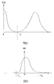
in the histogram of the grey levels. Nobuyuki Otsu "A threshold selection method
from grey-level histograms", IEEE Trans. on Systems, Man and Cybernetics, Vol.
SME-9, No. 1, January 1979 pp. 62-66 discloses such a method to find an optimal
threshold to segment the foreground objects from their background. Figure 1 of the
accompanying drawings illustrates a histogram of this type in which h(t) represents
the number of pixels and t represents the amplitude of the pixel values. The
controlled background is such that the majority of the background pixels have
relatively low levels whereas the foreground pixels have levels which tend to occupy
a higher range. Otsu attempts to define a threshold T in the valley between the two
ranges.
There are several problems with this technique. For example, although Figure 1
indicates that a well-defined valley exists between the background and foreground
grey level ranges, this is only the case for very carefully controlled backgrounds and
possibly some but certainly not all foregrounds.
If this technique is not restricted to very carefully controlled conditions, then the
problems become more severe. In particular, for many if not all images to be
segmented, significant numbers of foreground pixels will have levels extending below
the threshold whereas significant numbers of background pixels will have levels
extending above the threshold. Thus, any threshold T which is chosen will lead to
incorrect segmentation.
Another technique for segmenting an image is disclosed in T Fugimoto et al "A
method for removing background regions from moving images", SPIE vol. 1606
Visual communications and image processing 1991, imaging processing, pp. 599-606.
This technique makes use of both the level and polarity of the pixel values in order to
be resistant to lighting intensity fluctuations.
Figure 2 of the accompanying drawings is a histogram with the same axes as Figure 1
but illustrating the effect of lighting intensity fluctuations. In the absence of such
fluctuations, the distribution illustrated in the histogram has a narrow peak centred on
the vertical axis with symmetrically sloping sides. When a lighting intensity
fluctuation occurs, this peak becomes offset horizontally. The technique of Fugimoto
et al is to derive asymmetrical positive and negative thresholds T1 and T2 by
matching a Gaussian distribution to the actual position of the peak and simulating the
remainder of the curve, which is assumed to represent foreground pixel levels, with a
constant function. The intersection between the gaussian distribution and the constant
function gives the threshold values T1 and T2 for the image being processed. It is
then assumed that all pixel values between the thresholds represent noise.
This technique suffers from the same problems as Otsu. Although it may be resistant
to lighting intensity fluctuations, the selection of the thresholds cannot be made in
such a way that every image which is likely to be encountered will be correctly
segmented.
US 5 878 163 discloses an imaging target tracker and a method of determining
thresholds that are used to optimally distinguish a target from its background. The
target is assumed to occupy a grey level region which is identified from two
histograms corresponding to the inner and outer regions of the target, respectively.
Both histograms are recursively smoothed and a lookup table of actually observed
pixel values is then computed. Two optimal thresholds are selected and are set at
respective ends of histogram segments. The likelihood maps adapt over time to the
signature of the target. The grey-level distribution of the target is used to select
thresholds that pass a band of grey levels whose likelihood of their belonging to the
target is high. It is not necessary for an accurate segmentation for this type of
application.
JP 10/63855 discloses a method of extracting a desired object region. An image is
divided into colour regions, each comprising pixels of similar colours. An area of
attention is selected by a user and, if a colour region has a substantial overlap with
this area of attention, it is selected as part of the desired object. The entire area
comprising all selected colour regions is then defined as the desired object area. This
technique may be applied to a still image or a sequence of images. However, it
requires a predetermined area of attention and could contain background colour
regions which fall into this area.
While these methods may achieve reasonable results of segmentation for the desired
applications and are usually computationally efficient, the requirement of having a
carefully controlled background that can be distinguished from the target in either
intensity or colour severely limits the range of the applications available.
A more challenging task is therefore how to segment the foreground objects from the
background of a general scene. These methods often require the calculation of a
difference image which characterises the difference between the current frame and a
predetermined frame. The predetermined frame could be either a pre-recorded image
of the background, or the previous frame, or an image generated from a number of the
previous frames.
US 5 914 748 discloses an electronic compositing system for inserting a subject into a
different background. The method subtracts from each image of the sequence a pre-recorded
image of the background to generate a difference image. A mask image is
then generated by thresholding this difference image. The mask image is used to
segment the foreground objects from their background. The method is simple to
implement but may require manual correction by users to remove large artefacts in
both the segmented foreground regions and the background regions.
JP 5-89243 discloses a background image alternation device which uses three
consecutive frames to extract an object. Each line is scanned horizontally to detect
the whole edge of the object. Such a technique cannot be used with still images and
can only extract an object with a relatively simple shape.
JP 6-52311 discloses a method of extracting a moving object comprising three steps.
The first step detects static areas in each image. In this step, a difference image is
obtained as the absolute values of the direct difference of two consecutive images.
The difference image is then compared with a predetermined threshold value to
determine the static image area. A second step constructs a background image from
all static image areas extracted from all difference images. A third step identifies a
moving object by thresholding a difference image derived from the background image
formed in the second step and an input image. Such a technique can only be used
with a moving object and cannot therefore be used with a still image.
JP 2000-251079 discloses a dynamic picture object extracting technique which uses
time-directional luminance histograms. A histogram is constructed for each pixel
location to describe the luminance distribution in the temporal direction. The
histograms are used to define background pixels and moving object pixels. However,
each pixel needs its own histogram so that this technique requires very large amounts
of computing power and memory.
Such known techniques are computationally expensive and may not be suitable for
fast or even real-time applications, such as the cameras and mobile telephones
mentioned hereinbefore, which have limited computing power and memory capacity.
Further, it is difficult or impossible to implement such methods efficiently without
sacrificing performance.
US 5 848 183 discloses a system and method for generating and utilising histogram
data from a scanned document image. The histogram data may be generated using
image pixels from within a sample window, whose position and size need to be pre-determined,
for example, by the user using a user interface, or using a particular mark
or set of marks outlining the sample window boundary. It is then analysed to
determine a first grey value having a peak frequency associated with a white
background, a second grey value having a peak frequency associated with a black
threshold, and a third grey value having a minimum frequency associated with a
histogram of the image, and other grey values having a frequency equal to a quarter
and/or five-eighths of the peak frequency associated with the first and the second grey
values. These various grey values might be used to enhance the image contrast for a
reproduction machine.
US 6 043 900 modifies this method to detect the background type of a document
being scanned by a scanning system and to determine an optimal method to render the
image based on a leadedge histogram developed from scanning the image.
US 5 280 367 discloses a system that converts a scanned image of a complex
document into an image where text has been preserved and separated from the
background. The system first subdivides the scanned image into blocks and then
examines each block pixel by pixel to construct a histogram of the grey scale values
of the pixels. The histogram is partitioned into first, middle and last regions. If one
or more peaks occur in the first and last regions, and a single histogram peak occurs
within the middle region, the pixels are re-examined to determine the frequency of
occurrence of pixels having a grey scale level of the middle peak nearby pixels which
have a level of a first region peak. If this frequency is high, the middle peak is
assumed to be background information. After determining the threshold, the system
rescans the block applying the threshold to separate the text from background
information within the block.
US 5 831 748 discloses an image processor for a digital copying machine, in
particular for quickly removing a ground and a background of a document image. A
ground is an area where there is no information being recorded, such as a white base
area on white paper. A background is the area lying behind chief objects to be
reproduced or a less important part of a document relative to the chief objects. For
example, the black characters may be printed on a grey area which forms the
background. A histogram is generated for a plurality of regions in a document image,
or more preferably for each line. A ground tends to produce a peak at or near the
white level, black characters in the document are sparse and scatter widely at low
levels in the histogram, while a background tends to occupy a range below the ground
range. Three windows of the histogram may be defined to extract characteristic
qualities for grounds, backgrounds and characters separately. A window for the
ground quantity is determined according to the ground peak and a ground range for
removing the ground is determined by using the ground peak and the three
frequencies. The image data are then corrected according to the ground range and an
image is formed on a sheet of paper according to the corrected data so that the or each
ground can be removed without manual intervention.
1999 IEEE Computer Society Conference on Computer Vision and Pattern
Recoguition Proceedings, 23-25 June 1999, pp 459-464, Vol. 2, Gordon et al,
"Background estimation and removal based on range and colour" discloses a
technique for segmenting an image into foreground and background rgions based on
combining range segmentation and colour segmentation techniques. Although not
described clearly or in detail, the colour segmentation technique appears to be based
on analysing a sequence of frames containing moving foreground objects and, in
some way, deriving from this a non-occluded background image.
EP 1 115 254, the contents of which are incorporated herein by reference, discloses an
efficient technique for segmenting a sequence of pixellated images into foreground
and background regions. A difference image is formed as the difference between the
image to be segmented and an image of the non-occluded background. The
background and foreground regions of a preceding image are analysed so as to
provide a noise histogram corresponding to the background regions and a signal
histogram corresponding to the foreground regions. A first threshold is derived from
the noise histogram as the lowest level such that a predetermined proportion of the
background pixels have lower noise levels. A second threshold is derived from the
signal histogram as the highest level such that a predetermined proportion of the
foreground pixels have higher signal levels.
A difference image is formed as the difference between each pixel of the image to be
segmented and the corresponding pixel of a non-occluded background image. Each
pixel of the difference image is allocated as a background pixel if the value of the
difference image pixel is less than the first threshold and the pixel is surrounded by a
majority of neighbouring difference image pixels which are allocated to the
background region. Each remaining pixel is then allocated to the foreground region if
its value is greater than the second threshold and if it is surrounded by a majority of
neighbouring pixels allocated to the foreground region.
The remaining pixels are then allocated as candidate foreground or background pixels
by comparison with a third threshold between the first and second thresholds. Each
candidate pixel is then allocated as a background pixel if a majority of its
neighbouring pixels are already allocated to the background region or are candidate
background pixels. Remaining pixels are allocated to the foreground.
Although this technique is very effective for segmenting an image sequence with a
static background, it requires a pre-recorded image of a non-occluded background.
For example, this may be achieved by capturing one or more initial images of the
background before foreground objects can enter the field of view of a camera. This
type of method and other methods which compare an image to be segmented with a
background image are referred to hereinafter as "two-shot" methods.
The background should remain substantially the same during the entire image capture
process so that an image capture device should be mounted on a stable support. This
is inconvenient or impossible for many applications. For example, a user may wish to
hold a camera while focusing on another person. Once correct focusing has been
achieved, the user presses a start button to begin image capture. For convenience, it
should be possible to perform segmentation while allowing the camera to move, even
if only gradual movement is permitted. Two-shot methods are not suitable for such
applications and it is therefore desirable to have a "one-shot" technique, at least in
order to start segmentation, without having to have a background image available.
Also, for some applications such as where images are downloaded from the internet,
there may not be a background image available. A one-shot method is then essential.
There are many situations where there is only one image rather than a sequence of
images available for segmentation. Such situations require a "one-frame" method for
segmenting a single image without a prerecorded background image. As mentioned
hereinbefore, a technique for segmenting a single image may not be sufficiently
efficient for segmenting a video sequence. The terms "one-shot" and "one-frame" are
therefore used to distinguish the different situations.
According to a first aspect of the invention, there is provided a method of segmenting
a pixellated image having at least one foreground region partially occluding a
background and at least one non-occluded background region, comprising the steps
of:
The first visual characteristic may be a substantially uniform visual characteristic.
The first visual characteristic may be a substantially uniform colour.
Each pixel of the pixellated image may be represented by a plurality of colour
components, the step (a) may comprise forming a histogram for each colour
component of the number of pixels of at least part of the pixellated image for each
value of the colour component and detecting the colour component value of each
histogram at which the largest pixel number occurs, and the step (b) may comprise
ascribing the colour component values to each pixel of the first background image.
The at least part of the pixellated image may be selected manually and may comprise
at least part of the at least one background region.
The pixellated image may be of landscape format and the at least part of the pixellated
image may comprise side portions thereof.
The pixellated image may be of portrait format and the at least part of the pixellated
image may comprise a top portion thereof.
The pixellated image may be of portrait format and the at least part of the pixellated
image may comprise top corner portions thereof.
The step (b) may comprise ascribing the first visual characteristic to each pixel of the
first background image.
The method may comprise repeating the steps (a) to (d) at least once with the step (a)
comprising determining the first visual characteristic of at least some of the pixels
allocated as background pixels in the preceding step (d).
The method may comprise the subsequent steps of:
The second visual characteristic may be a substantially uniform colour.
Each second visual characteristic may be determined at least partly by the
corresponding visual characteristic of each pixel of the pixellated image
corresponding to a pixel of the block and allocated as a background pixel.
Each second visual characteristic may be determined at least partly by the first visual
characteristic.
The second visual characteristic of each block may comprise a linear combination of
the first visual characteristic and the corresponding visual characteristics of the pixels
of the pixellated image corresponding to pixels of the block and allocated as
background pixels.
The method may comprise repeating the steps (e) to (g) at least once with each second
visual characteristic being determined at least partly by the corresponding visual
characteristics of each pixel of the pixellated image corresponding to a pixel of the
block and allocated as a background pixel in the preceding step (g).
Each of the blocks may comprise a predetermined number of pixels. Each of the
blocks may comprise a square array of pixels. The method may comprise at least one
repetition, the or each repetition comprising performing the steps (e) to (g) at least
once with a reduced number of pixels in each block.
The method may comprise the subsequent steps of:
The third visual characteristic may be colour.
The third characteristic of each pixel of the third background image corresponding to
an allocated background pixel may comprise a linear combination of the
corresponding visual characteristic of the allocated background pixel and the first or
second visual characteristic.
In the step (h), each pixel of the third background image corresponding to an allocated
foreground pixel of the pixellated image may have the first or second visual
characteristic.
The method may comprise repeating the steps (h) to (j) at least once with the
background pixel allocation in the step (h) being determined in the preceding step (j).
The steps (c) and (d) may comprise the steps of:
The steps (f) and (g) may comprise the steps of:
The steps (i) and (j) may comprise the steps of:
The first predetermined proportion may be between 0.5 and 1 and may be
substantially equal to 0.75.
The first predetermined number may be substantially equal to half the number of
neighbouring difference image pixels.
The steps (k) to (n) may be repeated at least once with the at least one part in the step
(k) comprising the background pixels allocated in the preceding step (n).
Each step (n) may comprise forming a first initial histogram of values of the
difference image pixels allocated as background pixels and step (1) may derive the
first threshold from a first resulting histogram which comprises the sum of the first
initial histogram formed in the preceding step (n) and a first predetermined fraction
less than one of the first resulting histogram of the preceding step (1). The first
predetermined fraction may be a half.
The method may comprise the steps of:
The second predetermined proportion may be between 0.5 and 1 and may be
substantially equal to 0.75.
The second predetermined number may be substantially equal to half the number of
neighbouring difference image pixels.
The steps (o) to (q) may be repeated at least once with the at least one part of the step
(o) comprising the foreground pixels allocated in the preceding step (q).
Each step (q) may comprise forming a second initial histogram of values of the
difference image pixels allocated as foreground pixels and the step (p) may derive the
second threshold from a second resulting histogram which comprises the sum of the
second initial histogram formed in the preceding step (q) and a second predetermined
fraction less than 1 of the second resulting histogram of the preceding step (p).
The second predetermined fraction may be a half.
The method may comprise allocating each difference image pixel, which is not
allocated as a foreground or background pixel, as a candidate background pixel if a
value of the difference image pixel is less than a third threshold. The third threshold
may be between the first and second thresholds and may be the arithmetic mean of the
first and second thresholds.
The method may comprise allocating each difference image pixel, which is not
allocated as a foreground or background pixel, as a background pixel if more than a
third predetermined number of the neighbouring pixels are allocated as background
pixels or as candidate background pixels. The third predetermined number may be
half the number of neighbouring difference image pixels.
The method may comprise allocating each difference image pixel, which is not
allocated as a foreground or background pixel, as a foreground pixel.
The method may comprise forming a binary mask whose elements correspond to
difference image pixels, each element having a first value if the corresponding
difference image pixel is allocated as a background pixel and a second value different
from the first value if the corresponding difference image pixel is allocated as a
foreground pixel.
According to a second aspect of the invention, there is provided an apparatus for
segmenting a pixellated image having at least one foreground region partially
occluding a background and at least one non-occluded background region, comprising
means for determining a visual characteristic of the at least one background region,
means for generating a non-occluded background image from the visual
characteristic, means for comparing each of at least some of the pixels of the
pixellated image with a corresponding pixel of the background image, and means for
allocating each of the at least some pixels as a foreground or background pixel
depending at least partly on the comparing means.
According to a third aspect of the invention, there is provided an apparatus for
segmenting a pixellated image, comprising a programmable data processor and a
program for controlling the data processor to perform a method according to the first
aspect of the invention.
According to a fourth aspect of the invention, there is provided a storage medium
containing a program for controlling a data processor to perform a method according
to the first aspect of the invention.
According to a fifth aspect of the invention, there is provided a program for
controlling a data processor to perform a method according to the first aspect of the
invention.
According to a sixth aspect of the invention, there is provided an image capture
device including an apparatus according to the second or third aspect of the invention.
This technique may be used to segment a pixellated image into one or more
foreground regions and one or more relatively uniform background regions and does
not require a prerecorded image of a non-occluded background.
For segmenting a single image, a user can directly capture the image with a hand-held
image capture device and without requiring a stable support such as a tripod. For
capturing a sequence of images, the image capture device may also be hand-held so
long as any movement is gradual.
At least some embodiments of the invention may be thought of as being derived from
a two-shot method, for instance of the type disclosed in EP 1115254, with the
associated advantages of robustness and ease of implementation. For example, the
robustness of a two-shot method is maintained when segmenting a video sequence. In
some embodiments, the quality of the segmentation may be made self-improving as
segmentation proceeds. In such embodiments, the segmented results improve the
estimation of the noise and signal histograms, which in turn improve the next
segmentation to form a loop of continuous improvement.
This technique may be implemented in a computationally efficient way in terms of
computing power and memory requirement involving only simply arithmetic
operations which may be implemented exclusively using integers. The technique is
therefore very suitable for fast and even real-time applications, for example of the
type described hereinbefore.
The invention will be further described, by way of example, with reference to the
accompanying drawings, in which:
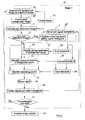
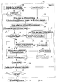
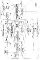
Figure 3 illustrates a method of segmenting an image using three stages 51, 52 and 53.
Each of the stages performs an iterative procedure which repeatedly approximates or
updates a background image and segments a pixellated image by comparing the image
with the estimated background image using a two-shot method based on the technique
disclosed in EP 1 115 254. In the first stage 51, the background image is estimated as
a completely uniform image. In the second stage 52, the background is updated as a
block-wise image. In the third and final stage 53, the background image is updated at
individual pixel resolution.
The method starts at 54 and, during the first iteration, the background image is
estimated as a uniform image at 55 using the following technique.
A colour image may be represented by a plurality of colour components, such as red
(R), green (G) and blue (B) colour components, luminence (Y) and two colour
difference components (U, V), or hue (H), saturation (S) and value (V). The present
technique may be applied to any colour format but, for convenience and without loss
of generality, the application of the technique to RGB components will be described
in detail hereinafter. Also, visual characteristics other than colour may be used to
estimate and represent the background image and these characteristics include image
entropy and texture (for example reprinted by Law's texture parameters).
Each pixel of an image I (x,y) may be denoted as R (x,y), G (x,y), B (x,y), where x
and y are discrete spatial coordinates of the pixel. If the pixel represents a foreground
object or region, it is referred to as a foreground pixel. If a pixel represents a
background region which is not blocked or occluded by a foreground object or region,
it is referred to as a background pixel.
The technique is applied to an image in which the background is substantially uniform
and comprises one or more regions all of substantially the same colour. Thus, all of
the background pixels have the same constant colour components R0, G0, B0, which
are thus independent of position.
In order to determine, for example, the red component R0, a histogram hr (r) is
generated from the red components of all of the pixels of the image, including
foreground pixels. In general, the image pixels have red colour components which
spread over a range but, because the background pixels all have the same red colour
component value, they form a peak in the histogram at the position R0 as shown in
Figure 4. If a sufficient number of background pixels are visible in the image, the
peak is generally substantially larger than any other peaks which may be present in
the histogram and which may be associated with common red colour components in
the foreground regions. Such a peak may readily be identified and its value R0
represents the red colour component of the pixels of the uniform background.
The same histogramming procedure is performed for each of the other colour
components so that the values of the three colour components of the background
pixels are determined. A uniform background image is then estimated or generated
by ascribing the three background colour components to all of the pixels of the
background image. This is equivalent to extrapolating the uniform background colour
to the occluded background region or regions behind the foreground region or
regions.
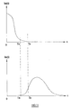
In practice, backgrounds in images are not completely uniform and, even where the
actual background is highly uniform, variations occur because of unevenness of the
physical surface of the background, background illumination non-uniformity,
shadows cast on the background by foreground objects, optical system aberations in
an image capture device and electronic noise in an image capture device. It is
therefore more usual for the colour components of the background regions to occupy
a small range rather than having a single value. This is illustrated in Figure 5, which
shows that a broader peak occurs in the histogram with the maximum value
corresponding to the commonest colour component value. Again, the red component
value R0 of the histogram maximum can be found and the background image is
generated by ascribing this value, and the corresponding values of the green and blue
components, to all of the pixels of the background image.
It is possible that foreground regions may have a relatively large area of uniform
colour which might produce a larger peak in the histogram than that corresponding to
the background region. In order to avoid this, background regions in the image may
be identified manually or automatically. For example, as illustrated in Figure 6, a
target foreground region 56 may be substantially centred in a "landscape format"
image with left and right side regions 57 containing only the background, in which
case the regions 57 may be selected in order to form the histogram. The selection of
such regions may be automatic because it does not need to be particularly accurate so
long as the majority of pixels in these regions are background pixels. This technique
is thus most likely to be useful for landscape format images.
For portrait format images, other regions are more suitable for being selected to form
the histogram. Figure 7 illustrates a typical composition of a portrait format image
such that the lower parts generally contain a foreground region with a relatively small
background region at the top of the image. In this case, the region 58 at the top of the
image may be selected for forming the histogram. As an alternative, Figure 8
illustrates selection of the top corner regions 59 for forming the histogram.
In some application, for example where the segmentation is performed off-line, it
may be possible to allow a user to select manually the background region or regions.
For example, the image may be displayed on a monitor and a user may use a mouse
pointer to select regions for use in forming the histogram.
In such a case, a boundary is drawn on the monitor by a user's operation (for example,
an operation of the mouse or an input pen) so as to select a background region.
Alternatively, the default boundary is displayed on the monitor, and then the user may
change the default boundary.
In the case of, for example, a landscape format image, a boundary between the
background region and the foreground region shown in Figure 6 are clearly displayed
on the monitor so that the user can check the boundary. When the user determines
that the boundary displayed on the monitor is inappropriate, the boundary is translated
rightward or leftward by a user's operation (for example, by operating a touch panel,
dragging the mouse, or operating buttons of a remote control or a keyboard). When
the user determines that the boundary displayed on the monitor is appropriate, the
boundary is finalized by a user's operation and thus selection of the background
region is terminated.
In the case of a portrait format image, the procedure is similar to the above such that
the boundary shown in Figure 7 is checked by the user on the monitor, and if
necessary, the boundary is translated upward or downward by a user's operation.
Then, the boundary is finalized and thus selection of the background region is
terminated.
The boundary shown in Figure 8 may be used instead of the boundary shown in
Figure 7. In this case, the boundary is checked by the user on the monitor, and if
necessary, the boundary is translated upward or downward, and rightward or leftward
by a user's operation. Then, the boundary is finalized and thus selection of the
background region is terminated.
The boundary is not limited to a straight line, but may be a zigzag line or a curve. For
example, a boundary formed of an ellipse or a curve which represents a rough profile
of the upper half of a human body may be prepared in advance. The movement of the
boundary is not limited to translation, but may involve rotation and/or deformation
(enlargement or reduction of a part of the entirety of the boundary).
Alternatively, a plurality of patterns may be prepared in advance for the boundary
such that the user can select one of the patterns to select the background region. The
selected pattern is displayed on the monitor. When the user determines that the
displayed pattern is inappropriate, the boundary may be moved, rotated and/or
deformed until the boundary is ready to be finalized by a user's operation as described
above.
In the above, selection of a background region by the user is described. Alternatively,
a background region may be obtained by fixing the boundary while moving the
camera. More specifically, the user checks an image taken by the camera during the
shooting, and adjusts the camera such that the subject is within the foreground region
while viewing the boundary displayed on the monitor. The camera may be adjusted
by, for example, directly moving the camera or using the zoom function of the
camera.
In some application, for example where the segmentation is performed off-line, it
may be possible to allow a user to select manually the background region or regions.
For example, the image may be displayed on a monitor and a user may use a mouse
pointer to select regions for use in forming the histogram.
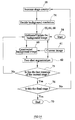
As shown in Figure 3, the estimated or generated background image is supplied as the
constructed background image 60, together with the image (where only one image is
available for segmentation) or the current image 61 (of a sequence of images) to the
two-shot segmentation procedure 62, which is based on the technique disclosed in EP
1 115 254 (the contents of which are incorporated herein by reference) and which is
illustrated in Figure 9, which is a block functional diagram in the form of an
"augmented" flow diagram illustrating the whole of the first stage 51 in more detail.
This drawing illustrates the supply of data as well as the sequence of steps or
operations.
The difference between each pixel of the current image 61 and each corresponding
pixel of the constructed background image 60 is calculated at 5 to determine a
difference image.
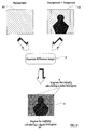
This is illustrated in Figure 10, which shows the background image 60 and current
image 61. The step 5 calculates the difference image which is illustrated at 8 in
Figure 10. The difference image has a noise region 9 where the pixels have values
mainly or wholly representing noise. The image 8 also has a signal region 10
corresponding to the foreground image with the pixels thereof representing a
difference between the image pixel and the corresponding background pixel of the
background image 60.
A step 3 determines that the difference image is the first such difference image and a
step 1c calculates noise and signal histograms 1d from statistical properties of the
background and foreground regions 9, 10 of the difference image 8.
After the step 1c or if the step 3 determines that the difference image is not the first
difference image, control passes to a step 11, which identifies strong candidates for
background pixels in the difference image. In particular, each pixel in turn is
compared with a first threshold, which is determined in a step 24 in accordance with
the statistical property of the noise determined in the step 1c. Pixels whose values are
below the first threshold and which are surrounded by a majority of neighbouring
pixels whose values are below the first threshold are allocated to the background
region (or one of the background regions where there is more than one such region).
A step 12 identifies strong candidates for foreground pixels by comparing each
difference image pixel not allocated to the at least one background region in the step
11 with a second threshold, which is determined in a step 25 in accordance with the
signal strength histogram of the signal region 10 determined in the step 1c. Those
pixels whose values are greater than the second threshold and which are surrounded
by a majority of neighbouring pixels whose values are above the second threshold are
allocated to the or each foreground region.
A step 13 then identifies whether the pixels not already allocated to the background or
foreground regions should be allocated to the at least one background region or the at
least one foreground region. Each such pixel is compared with a third threshold,
which is determined in a step 26 from and has a level between the first and second
thresholds. Those pixels whose levels are below the third threshold are identified as
candidate background pixels. Each of the candidate background pixels is then
allocated to the at least one background region if a majority of the neighbouring pixels
has already been identified as background pixels or as candidates for background
pixels. The remaining pixels are then allocated as foreground pixels.
In each of the steps 11,12 and 13, it is convenient for the whole of the difference
image to be thresholded followed by the "spatial filtering" to determine how the pixel
is to be allocated. However, for pixels near the edges and corners of each image, the
neighbourhood of each pixel is restricted. Although the spatial filtering may be
performed in the same way all the way to the image boundary, it may be more
appropriate, at least in some applications, to restrict the spatial filtering to a middle
portion of the or each image where each pixel has a full complement of neighbouring
pixels. This leaves a surrounding margin unfiltered.
For example, if the image size is M×N pixels and the window size used in the spatial
filtering is mxn pixels, then the central region comprising (M-m+1)×(N-n+1) pixels is
subjected to the spatial filtering and the pixels in the surrounding margin may be
spatially filtered using an appropriately smaller window size or may be left spatially
unfiltered. For applications where the segmentation does not need to be so precise,
the allocation of the pixels in the surrounding margin may be determined solely using
the thresholding and without the filtering process.
A step 14 forms a binary mask. In particular, the mask comprises elements
corresponding to the pixels of the difference image. Each pixel of the binary mask is
ascribed a first value if the corresponding difference image pixel is allocated to the at
least one background region or a second value different from the first value if the
corresponding difference image pixel is allocated to the at least one foreground
region. The binary mask thus represents the desired segmentation and may be used
for further processing of the image.
A step 16 updates the signal and noise histograms on the basis of an analysis of the
current image of the sequence and the updated histograms are returned to the step 1.
A step 17 determines whether a termination rule is met. If not, control returns to the
step 55. Otherwise, a "stage" counter is incremented by one at 18.
Any suitable termination rule may be used in the step 18. For example, stage 1 may
be terminated when the number of iterations reaches a predetermined number, which
may typically be set to 2 or 3.
During each subsequent iteration, the image is segmented in accordance with the
binary mask 14 and the step 55 estimates the background image on the basis of the
pixels identified as background pixels. Similarly, the noise and signal histograms are
updated in accordance with the statistical properties of the background and
foreground pixels as defined by the binary mask 14, which improves the next cycle of
segmentation.
The individual techniques used in the method illustrated in Figure 9 will now be
described in more detail.
The step 5 defines a difference image, D (x, y) which is given by:
D(x, y)= F[I(x, y), B(x, y)]
where F is a user-defined measurement that characterises the difference between I (x,
y) and B (x, y).
In the simplest case where both I(x, y) and B(x, y) are grey level images, for example,
D(x, y) may be defined as their direct difference, i.e.
D(x, y) = I(x, y) - B(x, y)
In the ideal case where there is no noise, the value of such a D(x, y) is then given by:
where s(x, y) is a measurement of the signal and ∈ means "is a member of". The term
s(x, y) represents a difference measurement between an object pixel and the pixel at
the same position in the background image. If all foreground pixels have yielded non-zero
signal values, then they can be identified and separated from those background
pixels which give a difference measurement of zero.
This simple approach does not work in practice because there is always noise in the
image and it is always possible that some object pixels may have identical values to
those corresponding pixels in the background image. To include the effect of noise,
the last equation may be modified as:
where the noise term n(x, y) is assumed to be a random variable with a mean value of
zero and a variance of σ.
To enable the segmentation of the foreground pixels from the background pixels, the
strength of the signal has to be significantly stronger than that of the noise. The above
equation may then be rewritten as:
where s(x, y) in the above equation may be regarded as containing an element of
noise, which in practice may not be distinguishable from the actual signal itself.
The simplest way to separate the signal term s(x, y) from the noise term n(x, y) is to
find a threshold T such that all foreground pixels have signal values exceeding T and
all background pixels have noise values below T. A binary masking function may
then be derived as:
where 1 denotes a foreground pixel and 0 a background pixel.
This is possible with some restrictive conditions, for instance, when the background is
in a uniform colour such as deep blue. The difference image D(x, y) may be
calculated using equation (3) which is described hereinafter. If the foreground objects
do not contain regions of the same deep blue and if the noise level of the imaging
system is low, the difference image should have strong signal values for the
foreground regions with very small values in the background regions. It is then
possible to find a threshold T to separate these signal and noise values.
In practice, this simplistic method may not work satisfactorily for a general scene of
the background. For example, some foreground pixels may be similar to the
corresponding background pixels and produce signal values that may be below any
given threshold T. Similarly, some background pixels may produce noise values
above T. There are many possible reasons that might cause this latter problem,
including the presence of electronic noise in the imaging system, lighting changes in
the background, and/or small disturbances of the imaging system. The multiple
thresholds of the present method substantially overcome this problem as described
hereinafter.
A commonly used difference measurements between two images I(x, y) and B(x, y) is
the colour distance:
F{I,B} = α(RI - RB )2 + β(GI - GB )2 + γ(BI - BB )2
where α, β, and γ are weighting factors and (RI, GI, BI} and {RB, GB, BB} are the
RGB colour components for the images I(x, y) and B(x, y), respectively.
It is often tempting to normalise the colour components in the above equation. The
normalisation is achieved by dividing each colour component by the sum of the
colour components. For example, the RI component may be normalised as:
R' I = RI RI + GI + BI
An example of F using such a normalised colour format is given by:
F{I,B} = α(R' I -R' B )2 + β(G'I - G'B )2 + γYI - YB
where YI = RI + GI + BI and YB = RB + GB + BB. While this normalisation is useful
in reducing the influence due to different lighting intensity, there is a drawback when
the value of YI or YB is very small. The division by a very small value will result in a
very large amplification of the noise elements in each colour component, thus making
any segmentation method difficult. This normalisation should therefore be applied
with care.
To reduce the computing cost, the colour distance measurement described in equation
(1) may be approximated as:
F{I,B} = α RI - RB + β GI - GB + γ BI - BB
The weighting factors may be pre-determined to reflect the importance of each colour
component. A typical set of values, α=β=γ=1, has been found adequate for many
applications. This leads to:
F{I,B} = RI - RB + GI - GB + BI - BB
There are other methods for defining the difference measurement function F. For
example, an entropy measurement may be used which is based on the statistical
property of the signal and the noise. Such a method may yield better difference
characteristics but tends to be more computing intensive.
Based on the difference measurement function F as described by equation (3), the
difference image D(x, y) is given by:
where the noise in each colour component is assumed to be a random variable with a
mean value of zero and a variance of σ. These random variables are also assumed to
be independent from one colour channel to another and from one pixel to another.
In theory, the values of the noise nr, ng and nb can vary from negative infinity to
positive infinity. In a real computer implementation, these values may be represented
by integers within a finite range, for example from -N to +N, where N is an integer
and is typically equal to 255. The values of |nr|, |ng| and |nb| then vary from 0 to N.
There is a reason for denoting noise terms as |nr|, |ng| and |nb| with the absolute value
operator ||. This will become clearer in the later discussion of noise reduction by
imaging averaging, which is applied before the absolute operations are applied.
The statistical property of the noise may be estimated initially using a histograming
method. For example, if the image I(x, y) contains the background only and is
captured at a different time from when B(x, y) is captured, then the difference image
D(x, y) represents the noise variable in each pixel. A histogram, hn(t), may then be
constructed by counting the total number of occurrences of a particular noise value t,
at which D(x, y)=| nr| + |ng| + |nb| =t. The upper graph of Figure 5 illustrates an
example of such a noise histogram.
Theoretically, the value of |nr| + |ng| + |nb| varies from 0 to 3N. This means that hn(t)
should have 3N elements or bins, each being an integer counter. However, the value
of |nr| + |ng| + |nb| will be equal to 3N if and only if all the three terms reach their
maximum value of N. In practice, the value of |nr| + |ng| + |nb| is likely to be far
below this maximum value of 3N. Often it is adequate to use a histogram of only N
bins. For those pixels that exceed the value of N, their values can be truncated to N.
This is useful when the computing power and the memory storage are limited.
This noise histogram has to be calculated before the segmentation starts. On the other
hand, it can only be calculated if the background pixels are already known. One
possible solution to these contradictory requirements is to find some likely
background regions in the image.
For example, the or each target may be initially positioned at the centre region of the
image with some regions 9 on the left and the right margins which contain the
background only, as illustrated in Figure 10. The regions 9 on the left and the right
margins may be used to estimate the noise histogram.
If the computation is carried out off-line for some applications, it is also possible to
allow the user to select manually background regions for estimating the noise
property. If the application is implemented on a personal computer (PC), for
example, an image may be displayed on the monitor and the user may use a mouse
pointer to select a region for this purpose.
Once the difference image is calculated, strong candidates of background pixels are
determined first using a first threshold Tn. The value of this threshold is so
determined that most foreground pixels have signal values above it and most
background pixels have noise values below it.
This threshold is determined from the noise histogram hn(t). Ideally the noise value is
bounded so that only the first few bins of the histogram are not zeros. The threshold
Tn is then the first value of t, above which the rest of bins are zeros. That is:
hn (t) = 0 for any t≥Tn
Unfortunately, such a near ideal situation does not normally exist.
While the histogram may not be all zeros over the higher range of t, the majority of
the noise values are usually clustered around the first few bins of the histogram as
illustrated in Figure 11. The rest of the bins tend to form a long tail that decreases in
general as t increases. The threshold Tn may then be defined as the smallest value of t
that is larger than a given percentage of the background pixels.
This threshold T
n is then related to a pre-set percentage value η
n, where 0.5<η
n≤1. It
is determined as the smallest T
n that satisfies the following inequality:
where K
n is the total number of background pixels and is given by:
The difference image is then thresholded using the first threshold T
n to identify strong
candidates for background pixels. A binary mask is given by
where 0 denotes a strong candidate for a background pixel and 1 those other pixels
which could be either foreground pixels or background pixels that fail to pass the
threshold. Only the strong candidates for background pixels are of interest here.
Those other pixels will be further classified in the processes described hereinafter.
For an image I(x, y) containing Kn background pixels, about ηn·Kn pixels will have
noise values below the threshold Tn. The remaining (1-ηn)·Kn pixels will have values
exceeding this threshold Tn and will fail to be detected as background pixels in this
process.
The implicit assumption here is that most of the foreground pixels have signal
strengths exceeding the first threshold. It is possible, however, that a small number of
foreground pixels might have signal values that fall below this threshold. This simple
thresholding method will falsely classify them as background pixels.
If the value of ηn is set higher, then the value of Tn is also higher and fewer
background pixels will fail to be detected. On the other hand, a larger threshold Tn
means it is easier for some foreground pixels to be falsely classified as background
pixels. Since an objective of the segmentation is to separate the moving objects from
the background, ideally the segmentation should be able to tell any difference
between the foreground objects and the background even when the signal values are
small. This means that, for segmentation purposes, the smaller the threshold Tn the
better. A compromise is therefore necessary and typically ηn is set to 0.75.
A true background pixel does not exist in isolation but is always connected to other
background pixels. If a pixel is indeed a background pixel, then it is likely that most
of its neighbouring pixels are also background pixels. Meanwhile, those foreground
pixels that are falsely detected as background pixels often present themselves as small
artefacts in the background. This observation leads to the following filtering method
to remove these falsely detected pixels.
For each current candidate of background pixel, a small neighbourhood, usually a
square window centred at the current pixel, is selected. If the total number of pixels
in this window is m, then it is expected that about ηn·m pixels are correctly classified
as background pixels where ηn > 0.5. This is correct if the value of m is sufficiently
large.
If a background pixel is in the vicinity of a foreground object, the small window may
contain some foreground pixels. Intuitively, about half of its neighbouring pixels are
background pixels and about half are foreground pixels, even if the current
background pixel is adjacent a foreground object. Obviously this is correct only if the
window size is sufficient small. This conflicts with the above requirement that m
should be "sufficiently large".
A compromise is therefore necessary. Heuristic results show that a typical value of m
is 100, thus giving a window size of 9x9 or 11x11 pixels. It is usual to have odd
numbers for the window size, so that the current pixel is arranged at the centre of the
window.
A candidate for a background pixel may then be accepted or rejected based on the
percentage ψ
n of background pixels in this neighbourhood. If ψ
n is larger than or
equal to 0.5, then it is accepted; otherwise it is rejected:
Computationally, this process may be implemented as a moving window averaging
operation applied to the binary image Mn(x, y) followed by a thresholding method
with a threshold of 0.5.
Similarly, the strong candidates for foreground pixels may be detected using a second
threshold Ts, which may be calculated from the signal histogram hs(t). As indicated
earlier, the signal histogram may not be initially available until the first image is
segmented. For the first image, this threshold may be simply estimated from Tn and is
given as:
Ts = µTn
where µ is a real number larger than 1. Typically µ is set to 1.5 to 2.
The above equation is used only for the initial estimation of the signal strength before
the first image is fully segmented. This equation may not be used if there is
additional information about the initial position of the foreground targets. If the
foreground objects are initially centred at the centre of the image as illustrated in
Figure 10, for instance, the central region of the image may then be used to construct
the initial signal histogram.
In general, the signal histogram h
s(t) is constructed from the segmented foreground
objects, which are available as soon as the first image is segmented. The second
threshold T
s is then defined as the largest value of t satisfying the following
inequality:
where 0.5 <η
s ≤1 and K
s is the total number of foreground pixels. A typical value of
η
s is 0.75.
Normally the threshold Ts is larger than Tn. If this is not the case, then it means that
the intensity and colour of the moving objects are so similar to the background that
their difference is smaller than the noise effect. The segmentation will then become
very difficult.
Once the second threshold T
s is obtained, it is used to threshold the difference image
to detect strong candidates for foreground pixels. A binary mask is obtained after the
thresholding:
Those pixels already identified as strong background pixels do not need to be
processed again but they will contribute to the filtering process as described below.
For an image I(x, y) containing K
s foreground pixels, about η
s·K
s, pixels will have
signal values above the threshold T
s. The remaining (1-η
s)·K
s pixels will have values
below this threshold T
s and will not be detected as foreground pixels in this process.
As in the detection of the strong candidates for background pixels, there are false
detections of background pixels as foreground pixels if the noise values pass the
second threshold T
s. These falsely detected pixels are normally distributed randomly
in isolation and may be removed using a moving window operation similar to the one
described hereinbefore. The criterion is also similar. If an initially identified
candidate foreground pixel has at least half of its neighbouring pixels as candidates
for foreground pixels, then it is confirmed as a foreground pixel; otherwise it is
rejected.
where ψ
s is the percentage of strong candidates for foreground pixels in the small
neighbourhood of the current pixel. The neighbourhood is usually selected as a
square window centred at the current pixel. Its size is normally set to 9x9 or 11x11,
as for detecting strong candidates for background pixels. Sometimes, if the
foreground objects are small, this window size may be reduced.
Those pixels that are neither accepted as strong candidates for background pixels nor
as foreground pixels may be classified in a further thresholding and filtering process.
A third threshold Tm is introduced and has a value between the thresholds Tn and Ts
given by
Tm=αTs + (1-α)Tn
where 0<α<1. Typically the value of α may be set to 0.5.
The difference image is thresholded again using this third threshold T
m. This time,
however, only those remaining pixels need be processed. The new binary mask
function is given by:
As in the previous processes, a filtering operation is applied to the "undetermined"
pixels. If more than half the pixels in the window are background pixels, then the
current pixel is classified as a background pixel and otherwise as a foreground pixel.
A binary mask is finally given by
where M(x, y) is the final binary mask and ψ
m is the percentage of foreground pixels
in a square window centred at the current pixel to be verified. As before, the window
size is normally 9x9 or 11x11 but may be adjusted to fit different sizes of objects.
Once the image is segmented using the binary mask M (x,y), the signal and the noise
histograms may be re-calculated using the foreground and background regions,
respectively. Also, the image may be saved together with the binary mask. The next
image is then obtained and segmented by repeating the above processes.
These steps may be repeated to form an iterative procedure. The signal and noise
histograms can then be re-calculated since the foreground and background regions are
now initially segmented. These re-calculated signal and noise histograms lead to
better estimation of the noise and signal thresholds Tn and Ts for the next iteration.
Alternatively, the signal and noise histograms may be updated using a cumulative
procedure. For example, the signal histogram may be updated as:
H t s (x) = Hs (x) + λH t-1 s (x)
where H t-1 / s(x) is the previous signal histogram used for segmenting the last frame,
Hs(x) is the new histogram obtained using the segmented results of the last frame and
λ is a constant which has a typical value of 1/2.
This is equivalent to have a weighted histogram from those previous ones, with the
closest frame being given a larger weight, e.g.
H t s (x) = H s (x) + 1 2 H t-1 s (x) + 1 4 H t-2 s (x) + ...
Similarly the noise histogram may be calculated using this cumulative method.
As shown in Figure 3, each time the stage counter is increased at 18, steps 64 and 65
determine which of the stages should be performed. Thus, once the termination rule
has been met at 17, the stage counter 18 increases the stage count to 2 and the steps 64
and 65 cause the second stage 52 to be performed. The second stage 52 is similar to
the first stage 51 and makes use of the same two-shot segmentation 62. However, the
second stage differs in that the background image is updated with block-wise
resolution at 66.
Although the background image is not generally entirely uniform, the colour changes
in the background regions are normally gradual. That is, the colours are almost
constant over a small area. An improved estimated image of the background image is
therefore constructed as a mosaic of small blocks, each having a constant colour.
For example, the background image may be divided into blocks of m x n pixels and
the image may contain k x 1 blocks, giving an image size of mk x nl pixels. Typically
m and n are set to the value of 8 or 16, giving a square of 8 x 8 pixels or 16 x 16
pixels. This is related to the block-based processing, for example, in MPEG
applications where each block typically contains 16 x 16 pixels in the Y component
and 8 x 8 pixels in the U and V components.
For a block at the ith position horizontally and jth position vertically, all pixels are
ascribed constant colour values R
i,j, G
i,j, B
i,j, where 0 ≤ i < k and 0 ≤ j < 1. The values
R
i,j, G
i,j and B
i,j take into account the "average" colour of the block and may differ
from block to block. The initially segmented background and foreground regions
provide useful information for this refinement. For example, the value of R
i,j may be
defined as
Ri,j = aR0 + (1 - a)Δ i,j
where 0 < α ≤ 1 and Δ
i,j is given by
where R(x,y) is the red colour component of each pixel in the current block and
M(x,y) is the binary mask. The more background pixels are in the current block, the
more they contribute to the value of Δ
i,j.
If there is no background pixel in the current block, the value of Δi,j is equal to R0 and
so is the value of Ri,j.
If all pixels in the block are background pixels, then the total number of background
pixels is equal to mn. The value of Δi,j then represents largely the averaged colour of
this block. Typically α is set to 0.5, so that Ri,j is about the mean of R0 and Δi,j.
Similarly the values of Gi,j and Bi,j are calculated. A background image consisting of
a mosaic of these blocks is then constructed, thus giving a better approximation of the
true background.
Stage 2 is repeated until a step 67 determines that a termination rule is met. For
example, the termination rule may be that a predetermined number, such as between 5
and 10, of iterations has been performed. When the termination rule is met, the stage
counter 18 is increased and the steps 64 and 65 cause the third stage 53 to be
performed.
The block-wise updating of the background image is an improvement to the
absolutely uniform image used at Stage 1. However, it can be further improved, in
particular in areas around the boundaries of the foreground objects or where there are
more dramatic colour changes in the background. This is achieved at 68 by
refinement at a pixel-based resolution so that the background image reflects the actual
background as closely as possible.
If a pixel is classified as a background pixel, its value is used directly to update the
background image. At a position where a pixel is classified as a foreground pixel, the
corresponding pixel in the background image is replaced with the corresponding
background pixel value from the second stage 52. The background image and the
current image may be described as {Rbg(x,y), Gbg(x,y), Bbg(x,y)} and {R1(x,y),
G1(x,y), B1(x,y)}, respectively.
The following is the equation to update the red component of the background image:
where 0 <α≤1 and R
i,j is the value from the second stage 52. Typically α is set to ½.
The green and the blue components of the background image are updated in the same
way.
A step 69 determines when a termination rule for the third stage 53 is met. For
example, the third stage may be terminated when the total number of iterations
exceeds a pre-defined number which is typically set between 10 and 20.
Segmentation of the image is then complete and the process ends at 70.
The segmentation results can be improved if the noise level can be reduced. As
mentioned earlier, the noise terms nr, ng, nb are independent random variables from
pixel to pixel. Here the noise terms are the direct difference before the absolute value
operation is applied. On the other hand, the signal values for foreground pixels tend
to be correlated with each other over a small neighbourhood. For the red component,
for example, a direct difference image Dr may be obtained as:
Dr (x, y) = RI (x,y) - RB (x, y)
If a moving window averaging operation is applied to this image before the absolute
value operation is applied, then the noise variance will be reduced while the averaged
signal will remain about the same, provided that the window size is small. For
simplicity, it is assumed that each of the noise terms nr, ng, nb has a variance of σ. For
a window size of nxn pixels, the noise variance of the smoothed image is reduced
from σ to σ/n. Typically the window size is set to 3x3, so that the noise variance in
each colour component is reduced by a factor of 3. This operation may be applied to
all three colour components before the absolute value operator is applied to produce
the difference image defined by equation (3).
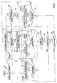
Figure 12 illustrates a method which differs from that illustrated in Figure 9 in that it
is modified to include noise reduction. The step 5 comprises sub-steps 5a to 5c. The
step 5a calculates the direct difference images for all colour components or channels
and the step 5b performs the moving window averaging operation so as to provide
noise reduction in each of the direct colour component difference images. The step 5c
then generates the final difference image.
The performance of the algorithm is closely related to the uniformity of the
background regions in the video images. The colour changes in the background
regions make the estimation of the background image difficult, thus resulting in
artifacts in the segmented background.
The uniformity of the background regions may be improved by applying a colour
transformation method. For example, a logarithm function might be applied to the
whole image, so that the colour changes become less significant in the background.
Unfortunately the logarithm function also reduces the overall colour ranges, thus
making it harder to separate the foreground regions from the background regions.
Since the background is roughly uniform, the colours are clustered around the most
common colours and the colour ranges of the background are relatively small in
comparison with that of the foreground. Only these colour ranges of the background
need to be reduced. This observation leads to the development of a new colour
transformation method which is based on a piecewise linear function.
The first step of this method is to determine the most common colours in the
background and their ranges. This may be illustrated with the red component. After
the first image is segmented, a histogram H(R) is constructed using all pixels in the
background. The largest peak is found at position R
0, which represents the most
common red component in the background. Once the peak is found, a search is
carried out from both sides of the peak to determine a colour range [R
1, R
2], where 0
≤ R
1 ≤ R
0 and R
0 ≤ R
2 ≤ 255 if the overall colour range is [0, 255]. The values of R
1
and R
2 are determined in the following procedure:
Typically α is set to 50%, such that 50% of the background pixels have red colours
within the range of [R
1, R
2]. A piecewise linear function may then be used to scale
the overall colour range [0, 255]. A general form of this is given by
where f
1(R), f
0(R), and f
2(R) are linear and increasing functions that satisfy the
following conditions:
The following is an example set of functions that satisfy the above conditions:
where
Typically a0 is set to ½ and both a1 and a2 to 1.
Similar scaling functions may be derived and applied to the green and blue colours.
These colour transformations may be applied before the difference image is
calculated.
Once the segmentation is carried out, the static background may be removed and
replaced with a new background image. The new background image may have a
large contrast with the foreground objects, thus having a clear cut-out at the boundary
around the foreground objects. This may be "softened" by applying a smoothing
operation for boundary pixels.
An object pixel is regarded as inside the object if all its adjacent pixels are also
foreground pixels. These adjacent pixels may be defined as the 4-connected
neighbours as illustrated at 71 in Figure 13 or the 8-connected neighbours as
illustrated at 72 in Figure 13. There is no operation required for object pixels inside
the object.
If at least one of the adjacent pixels is a background pixel, an object pixel is then
regarded as on the boundary. This pixel may be replaced by a new pixel given by:
I'(x,y) = εI(x,y) + (1-ε)B'(x,y)
where B'(x,y) is the user selected new background image and ε is a constant which
has a typical value of ½.
In the embodiment described hereinbefore, the background image is estimated and
updated at three different resolutions. This might be extended to more than three
stages, each of which has a finer resolution than that of the previous one as shown in
Figure 14. This is achieved by changing the block size, starting with the whole image
and ending with pixel resolution. The block size might be reduced by a fixed step or
by a factor of 2 so that the block size at each stage is half of that of the previous stage.
If the image has NxN pixels and N is an integer comprising a power of 2, i. e.2n, then
the total number of stages will be n+1.
The method shown in Figure 14 begins with the first stage shown at 51 in Figure 3
with the whole of the background region or regions being assumed to have the same
colour. A step 75 checks whether each stage has performed the intended number of
iterations and, when this is achieved, a step 76 determines whether the final stage has
been performed. If not, the stage counter is increased at 18 and the background
resolution for the next stage is decided at 74. The background resolution is thus
progressively increased for each stage until pixel-level resolution is achieved in the
final stage. Thus, each intermediate stage corresponds to the second stage 52 of
Figure 3 with one or more block-wise resolutions and the final stage corresponds to
the third stage 53 in Figure 3.
The methods described so far are one-frame methods aimed at segmenting a single
image. However, the method may be extended to form a one-shot method. The one-frame
method may be applied to the first frame, and the background image may then
be used to segment the next image. The segmentation for these following images
however may comprise only one stage by updating the background image at pixel
resolution. The iteration number for the second image may be set to a fixed number
L, which has a typical value of 10. The iteration number for the following images
may then be reduced to a smaller number k, where k<L. For example, the iteration
number In(i) may be given by
In(i) = max{k, L - i + 1}
where i is the image number starting from 0 for the first image.
This technique is illustrated in Figure 15, which differs from that of Figure 3 by the
addition of steps 80, 81 and 82. The next image in the sequence is obtained at 80 and
the three stage segmentation is performed on this image. In particular, the step 81
determines that this is the first image and the steps 64 and 65 ensure that the second
and third stages 52 and 53 are performed after the first stage 51.
For all subsequent images, the step 81 causes only the third stage 53 to be performed.
This continues until the last image of the sequence is detected in the step 82 and the
process ends.
In the embodiments described hereinbefore, the termination rule for each stage was
that a predetermined number of iterations had been performed. However, other
termination rules may be used and Figure 16 illustrates a method which differs from
that shown in Figure 3 in that the method is terminated after a predetermined time
even if the three stages have not been completed. In particular, after each
segmentation 62, a step 84 tests whether a preset timer has timed out and, if so, the
method is immediately ended at 70.
Figure 17 illustrates a method which differs from that shown in Figure 16 in that user
interaction is permitted. In particular, after the third stage 53 has been performed, an
image is composed at 85 and the result is checked at 86. If the result is acceptable,
the process ends at 70. However, if the result is not acceptable, the method is
performed again on the image, possibly with further user intervention in order to try
to obtain an acceptable result.
The method may be performed on any suitable apparatus such as that illustrated in
Figure 18. A programmed data processor comprises a central processing unit (CPU)
30 connected to a CPU bus 31. A system memory 32 is connected to the bus 31 and
contains all of the system software or program for operating the data processor.
The images are obtained by an imaging device 33, such as the Sharp® Internet
ViewCam, which is connected to video a digitiser 34 (if the image signal is not
already in digital data format) connected to a data bus 35. An optional display device
36 may also be connected to the data bus 35 so that the input may be displayed in full
screen or in a window if the output image is also displayed in another window.
Alternatively, the incoming images may be from other sources and may already be in
the form of a computer file which may be stored in a hard disk or any other storage
device 37 connected to the data bus 35.
The system comprises a frame buffer 38 for storing an incoming image, a frame
buffer 39 for the image of the background, a frame buffer 40 for the binary mask and
other memory buffers 41 as necessary for temporary data generated during the
segmentation process.
The segmented foreground and background regions together with the binary mask
may be sent to other devices for further processing or may be stored in other storage
devices such as a hard disk.
A composed image may be generated using the segmented foreground region(s) and
any user-designated new background image. The new composed image may be
displayed on the display device 36 either in full screen or in a window for comparison
with the original image as displayed in a separate window.