EP1244156A2 - One-piece header assembly for hermetic battery terminal feedthrough, fill and closure designs - Google Patents
One-piece header assembly for hermetic battery terminal feedthrough, fill and closure designs Download PDFInfo
- Publication number
- EP1244156A2 EP1244156A2 EP01129871A EP01129871A EP1244156A2 EP 1244156 A2 EP1244156 A2 EP 1244156A2 EP 01129871 A EP01129871 A EP 01129871A EP 01129871 A EP01129871 A EP 01129871A EP 1244156 A2 EP1244156 A2 EP 1244156A2
- Authority
- EP
- European Patent Office
- Prior art keywords
- casing
- electrochemical cell
- header
- opening
- anode
- Prior art date
- Legal status (The legal status is an assumption and is not a legal conclusion. Google has not performed a legal analysis and makes no representation as to the accuracy of the status listed.)
- Granted
Links
Images


Classifications
-
- H—ELECTRICITY
- H01—ELECTRIC ELEMENTS
- H01M—PROCESSES OR MEANS, e.g. BATTERIES, FOR THE DIRECT CONVERSION OF CHEMICAL ENERGY INTO ELECTRICAL ENERGY
- H01M50/00—Constructional details or processes of manufacture of the non-active parts of electrochemical cells other than fuel cells, e.g. hybrid cells
- H01M50/10—Primary casings, jackets or wrappings of a single cell or a single battery
- H01M50/172—Arrangements of electric connectors penetrating the casing
- H01M50/174—Arrangements of electric connectors penetrating the casing adapted for the shape of the cells
-
- H—ELECTRICITY
- H01—ELECTRIC ELEMENTS
- H01M—PROCESSES OR MEANS, e.g. BATTERIES, FOR THE DIRECT CONVERSION OF CHEMICAL ENERGY INTO ELECTRICAL ENERGY
- H01M50/00—Constructional details or processes of manufacture of the non-active parts of electrochemical cells other than fuel cells, e.g. hybrid cells
- H01M50/10—Primary casings, jackets or wrappings of a single cell or a single battery
- H01M50/102—Primary casings, jackets or wrappings of a single cell or a single battery characterised by their shape or physical structure
- H01M50/103—Primary casings, jackets or wrappings of a single cell or a single battery characterised by their shape or physical structure prismatic or rectangular
-
- H—ELECTRICITY
- H01—ELECTRIC ELEMENTS
- H01M—PROCESSES OR MEANS, e.g. BATTERIES, FOR THE DIRECT CONVERSION OF CHEMICAL ENERGY INTO ELECTRICAL ENERGY
- H01M50/00—Constructional details or processes of manufacture of the non-active parts of electrochemical cells other than fuel cells, e.g. hybrid cells
- H01M50/10—Primary casings, jackets or wrappings of a single cell or a single battery
- H01M50/102—Primary casings, jackets or wrappings of a single cell or a single battery characterised by their shape or physical structure
- H01M50/107—Primary casings, jackets or wrappings of a single cell or a single battery characterised by their shape or physical structure having curved cross-section, e.g. round or elliptic
-
- H—ELECTRICITY
- H01—ELECTRIC ELEMENTS
- H01M—PROCESSES OR MEANS, e.g. BATTERIES, FOR THE DIRECT CONVERSION OF CHEMICAL ENERGY INTO ELECTRICAL ENERGY
- H01M50/00—Constructional details or processes of manufacture of the non-active parts of electrochemical cells other than fuel cells, e.g. hybrid cells
- H01M50/10—Primary casings, jackets or wrappings of a single cell or a single battery
- H01M50/102—Primary casings, jackets or wrappings of a single cell or a single battery characterised by their shape or physical structure
- H01M50/109—Primary casings, jackets or wrappings of a single cell or a single battery characterised by their shape or physical structure of button or coin shape
-
- H—ELECTRICITY
- H01—ELECTRIC ELEMENTS
- H01M—PROCESSES OR MEANS, e.g. BATTERIES, FOR THE DIRECT CONVERSION OF CHEMICAL ENERGY INTO ELECTRICAL ENERGY
- H01M50/00—Constructional details or processes of manufacture of the non-active parts of electrochemical cells other than fuel cells, e.g. hybrid cells
- H01M50/10—Primary casings, jackets or wrappings of a single cell or a single battery
- H01M50/172—Arrangements of electric connectors penetrating the casing
-
- H—ELECTRICITY
- H01—ELECTRIC ELEMENTS
- H01M—PROCESSES OR MEANS, e.g. BATTERIES, FOR THE DIRECT CONVERSION OF CHEMICAL ENERGY INTO ELECTRICAL ENERGY
- H01M50/00—Constructional details or processes of manufacture of the non-active parts of electrochemical cells other than fuel cells, e.g. hybrid cells
- H01M50/60—Arrangements or processes for filling or topping-up with liquids; Arrangements or processes for draining liquids from casings
- H01M50/609—Arrangements or processes for filling with liquid, e.g. electrolytes
- H01M50/627—Filling ports
- H01M50/636—Closing or sealing filling ports, e.g. using lids
-
- H—ELECTRICITY
- H01—ELECTRIC ELEMENTS
- H01M—PROCESSES OR MEANS, e.g. BATTERIES, FOR THE DIRECT CONVERSION OF CHEMICAL ENERGY INTO ELECTRICAL ENERGY
- H01M10/00—Secondary cells; Manufacture thereof
- H01M10/05—Accumulators with non-aqueous electrolyte
-
- H—ELECTRICITY
- H01—ELECTRIC ELEMENTS
- H01M—PROCESSES OR MEANS, e.g. BATTERIES, FOR THE DIRECT CONVERSION OF CHEMICAL ENERGY INTO ELECTRICAL ENERGY
- H01M6/00—Primary cells; Manufacture thereof
- H01M6/14—Cells with non-aqueous electrolyte
- H01M6/16—Cells with non-aqueous electrolyte with organic electrolyte
-
- Y—GENERAL TAGGING OF NEW TECHNOLOGICAL DEVELOPMENTS; GENERAL TAGGING OF CROSS-SECTIONAL TECHNOLOGIES SPANNING OVER SEVERAL SECTIONS OF THE IPC; TECHNICAL SUBJECTS COVERED BY FORMER USPC CROSS-REFERENCE ART COLLECTIONS [XRACs] AND DIGESTS
- Y02—TECHNOLOGIES OR APPLICATIONS FOR MITIGATION OR ADAPTATION AGAINST CLIMATE CHANGE
- Y02E—REDUCTION OF GREENHOUSE GAS [GHG] EMISSIONS, RELATED TO ENERGY GENERATION, TRANSMISSION OR DISTRIBUTION
- Y02E60/00—Enabling technologies; Technologies with a potential or indirect contribution to GHG emissions mitigation
- Y02E60/10—Energy storage using batteries
-
- Y—GENERAL TAGGING OF NEW TECHNOLOGICAL DEVELOPMENTS; GENERAL TAGGING OF CROSS-SECTIONAL TECHNOLOGIES SPANNING OVER SEVERAL SECTIONS OF THE IPC; TECHNICAL SUBJECTS COVERED BY FORMER USPC CROSS-REFERENCE ART COLLECTIONS [XRACs] AND DIGESTS
- Y02—TECHNOLOGIES OR APPLICATIONS FOR MITIGATION OR ADAPTATION AGAINST CLIMATE CHANGE
- Y02P—CLIMATE CHANGE MITIGATION TECHNOLOGIES IN THE PRODUCTION OR PROCESSING OF GOODS
- Y02P70/00—Climate change mitigation technologies in the production process for final industrial or consumer products
- Y02P70/50—Manufacturing or production processes characterised by the final manufactured product
-
- Y—GENERAL TAGGING OF NEW TECHNOLOGICAL DEVELOPMENTS; GENERAL TAGGING OF CROSS-SECTIONAL TECHNOLOGIES SPANNING OVER SEVERAL SECTIONS OF THE IPC; TECHNICAL SUBJECTS COVERED BY FORMER USPC CROSS-REFERENCE ART COLLECTIONS [XRACs] AND DIGESTS
- Y10—TECHNICAL SUBJECTS COVERED BY FORMER USPC
- Y10T—TECHNICAL SUBJECTS COVERED BY FORMER US CLASSIFICATION
- Y10T29/00—Metal working
- Y10T29/49—Method of mechanical manufacture
- Y10T29/49002—Electrical device making
- Y10T29/49108—Electric battery cell making
- Y10T29/4911—Electric battery cell making including sealing
-
- Y—GENERAL TAGGING OF NEW TECHNOLOGICAL DEVELOPMENTS; GENERAL TAGGING OF CROSS-SECTIONAL TECHNOLOGIES SPANNING OVER SEVERAL SECTIONS OF THE IPC; TECHNICAL SUBJECTS COVERED BY FORMER USPC CROSS-REFERENCE ART COLLECTIONS [XRACs] AND DIGESTS
- Y10—TECHNICAL SUBJECTS COVERED BY FORMER USPC
- Y10T—TECHNICAL SUBJECTS COVERED BY FORMER US CLASSIFICATION
- Y10T29/00—Metal working
- Y10T29/49—Method of mechanical manufacture
- Y10T29/49002—Electrical device making
- Y10T29/49108—Electric battery cell making
- Y10T29/49114—Electric battery cell making including adhesively bonding
Landscapes
- Chemical & Material Sciences (AREA)
- Chemical Kinetics & Catalysis (AREA)
- Electrochemistry (AREA)
- General Chemical & Material Sciences (AREA)
- Sealing Battery Cases Or Jackets (AREA)
- Connection Of Batteries Or Terminals (AREA)
- Battery Mounting, Suspending (AREA)
- Primary Cells (AREA)
Abstract
Description
- The present invention relates to an improvement in electrochemical cell designed by enhancing manufacturing of a battery case, particularly a clam shell variety. A clam shell casing comprises two plate-shaped members, each having a surrounding rim mated to form the enclosure. More specifically, the invention is directed to a one piece lid or header design containing a hermetic glass to metal seal (GTMS) for a terminal feed through and an electrolyte filling port. While particularly suitable for clam shell casing designs, the present one-piece lid is also useful other with casing constructions as well.
- In prior and current product lines, the design of electrochemical cells includes a lid with separate ferrules or openings for providing a terminal pin feedthrough, and an electrolyte fill and closure mechanism. Designs for these functions usually consist of a lid, GTMS ferrule, and an electrolyte fill ferrule which are welded together to form a subassembly. This subassembly is further manufactured by having the GTMS inserted into its ferrule and the completed assembly is then welded into a battery case of various configurations. The battery is filled with electrolyte via the fill ferrule or area, and the fill mechanism is welded shut. In this embodiment, there are three components in the lid subassembly requiring four welds for completion.
- Another prior art technique requires that the lid be of sufficient thickness to facilitate glassing and installing a fill closure directly into the lid without the provision of ferrules. However, this method has distinct disadvantages since the entire lid must be of increased thickness which in turn reduces the available internal volume of the cell. The prior art describes these various configurations.
- For example, JP 406068861A shows a lid for a lithium battery which has a terminal feedthrough, a fill port, and a GTMS provided directly into the cell lid with no ferrules. The battery does not appear to be of a clam shell type. The thin case design of the clam shell would make adaptation of this technology very expensive and moreover, would not be adaptable to other battery configurations.
-
WO 92/10859 shows an electrochemical cell lid with a fill port as well as a terminal feedthrough. The GTMS is provided with a ferrule. However, while the fill port does not have a ferrule, there is an integrally machined boss portion for supporting a plug. Again, the casing is of a conventional prismatic shape, and not of a clam shell type. This type of fill arrangement is unsuitable for use with a clam shell design and further shows the need for the current invention. - U.S. Patent No. 5,306,581 to Taylor et al. relates to a battery with a weldable terminal feedthrough including an insulator welded to an aperture in the header. The fill port includes a shaped portion of the lid extending downwardly into the interior of the casing and an integral upstanding ring surrounding the fill plug. Again, adaptation of this design to a clam shell case would be difficult, and resultantly very expensive.
- Thus, as previously stated, the problem with the prior art lid or header designs is that a number of pieces need to be assembled and welded to create a hermetically sealed battery terminal feedthrough, and fill port. The new design, the subject of the current patent application, reduces the number of pieces required for a casing lid or header from three to one and reduces the number of welds required from four to two. The new design allows for greater flexibility in battery design while enhancing cell volumetric efficiency.
- Accordingly, the present invention is directed to an electrochemical cell having plate electrodes housed inside mating "clam shell" casing components. A one piece metallic lid or header design is used in conjunction with the clam shell case, the lid containing both a hermetic glass-to-metal seal for a terminal lead and a filling port. When mated together, the casing components are form-fitting with respect to the internal battery structure so as to reduce the overall size of the electrochemical package.
- The foregoing and additional advantages and characterizing features of the present invention will . become clearly apparent upon reading the ensuing description together with the included drawings wherein:
- Fig. 1 is a plan view of the battery lid or header assembly of the present invention.
- Fig. 2 is a section view of the assembly cut along line 2-2 in Fig. 1.
- Fig. 3 is a perspective view of an embodiment of the clam shell halves of the battery casing.
- Fig. 4A is a perspective view of an embodiment of the clam shell battery casing with the lower portion containing the feed through assembly.
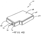
- Fig. 4B is a perspective view of the battery case assembled prior to welding.
- Fig. 5 is a sectional view of the lower half of the battery casing cut along line 5-5 in Fig. 4A showing the connection of the cathode to the collection plate.
- Fig. 6 shows a plan view of an embodiment of the battery case containing the header assembly.
- Fig. 7 shows a perspective view of an embodiment of the clam shell case in which the battery header assembly is being installed by welding using a laser source.
- Fig. 8A depicts the first embodiment of the seal closure for the fill port.
- Fig. 8B depicts the second embodiment of the seal closure for the fill port.
- Fig. 8C depicts the third embodiment of the seal closure for the fill port.
- Turning now to the drawings, Figs. 3, 4A and 4B illustrate an
electrochemical cell 20 having a one-piece header assembly 70 according to the present invention. Theheader assembly 70 will be described in detail hereinafter. First, thecell 20 includes a conductive casing ofmetal 23, such as stainless steel, having first and secondclam shell portions clam shell portions electrode assembly 26. The preferred methods of sealing are welding and brazing. - In particular, the
first clam shell 22 comprises spaced apartside walls end walls side walls end walls front wall 36. Opposite thefront wall 36 is ancontinuous edge 38 ofside walls end walls - The
second clam shell 24 comprises spaced apartside walls end walls side walls walls front wall 48. Opposite the front wall is a continuous edge 50 of theside walls walls End wall 46 has a greater length thanend wall 44. In this manner,side wall 40 includes a first portion 52 extending fromend wall 44 and forming into an angledside wall portion 54 which meets asecond portion 56 ofside wall 40 extending to theend wall 46. - In one preferred embodiment of the present invention shown in Fig. 4B, the
second clam shell 24 is sized to fit inside the periphery of thefirst clam shell 26 in a closely spaced relationship. This means thatside wall 42 is somewhat shorter thanside wall 28,end wall 46 is somewhat shorter thanend wall 32,side wall 40 is somewhat shorter thanside wall 30 andend wall 44 is somewhat shorter thanend wall 34. Also, the first andsecond portions 52 and 56 ofside wall 40 are sized to be received inside the first andsecond portions side wall 30 with the intermediate angledside wall portion 54 ofside wall 40 aligned with and received inside of the intermediate angled side wall portion 62 ofside wall 30. - In the embodiment of the present invention as further shown in Fig. 4B, the
second clam shell 24 is received and nested inside thefirst clam shell 22 in a closely spaced relationship. In that respect, themating clam shells - As shown in Fig. 4A,
cell 26 further includes an anode electrode, generally designated 64. The anode electrode comprises an anode active material, such as lithium pressed to the opposite sides of an anode current collector. The anode current collector is fabricated from a thin sheet of metal such as nickel. Theanode electrode 64 is in operative contact with acathode plate 66 through a thin sheet ofseparator material 68. The separator surrounds and envelopes thecathode body 66 to prevent direct physical contact with theanode 64. - As shown in Figs. 1, 2, 4A and 4B the case further contains a one-piece header or
lid assembly 70 of the present invention provided with first andsecond openings first opening 72 is used for a hermetically sealedbattery terminal feedthrough 78 whereas thesecond opening 74 is used for an electrolyte fill opening. After filling the casing with electrolyte, a closure member 80 (Fig. 5) may be sealed therein using a laser weld (not shown). - In Figs. 1 and 2, the
upper surface 82 of theheader assembly 70 is surrounded by astep 71 which leads to spaced apart sidewalls 84 and 86 extending to and meeting with acurved wall 88. Theside walls 84 and 86 further extending and meeting with acurved wall 90. Thesidewalls 84 and 86 andcurved walls lower surface 92 at a rounded edge.Side walls 84 and 86, and endwalls step 71 is to assist in locating the one-piece header assembly 70 in theside face 34 of theclam shell portion 22. Thelower portion 108 of theassembly 70 acts as a heat sink and dissipates heat generated by welding or brazing of theassembly 70 in the clam shell halves 22 and 24. The welding method is shown in Fig. 7. As those skilled in the art can appreciate, theheader assembly 70 can be installed in either the first or second, or possibly in both the first and second, clam shell halves 22 and 24 depending on the design of the battery system. There can be a number of embodiments of the assembly location. - The dimension of the
step 71 depends on the type and nature of the battery and the case used therein. In general, the vertical dimension of the step will be equal to the thickness of the battery case. As previously stated, thestep 71 assists in the locating of the assembly in the wall of the battery casing. Thestep 71 maintains theassembly 70 in position whereby theupper surface 82 of the assembly is coplanar with the outer surface 33 ofside wall 34, creating a smooth transition which may be necessary in certain battery designs. - The
first opening 72 of theassembly 70, is further defined by a continuous cylindrical opening of fixed radius 94. In that respect, theopening 72 extends downwardly from theupper surface 82 and meets withlower surface 92. The continuous cylindrical opening is used for a battery terminal feedthrough, and contains glass-to-metal seal 76. - The
second opening 74 is further defined by a discontinuous cylindrical aperture of fixedradius r 1 96 extending downwardly from thetop surface 82 to a point approximately midway between the top 82 andbottom surface 92 where the opening passes through atransition 95 to a cylindrical 98 opening of radius r2 (where r1>r2)extending further downward and meeting with thelower surface 92. The first andsecond openings - It is not necessary that the joinder of aperture surfaces 94, 96 and 98 of the upper and
lower surfaces metallic component 70 will produce varied surface finishes. The one-piece header assembly 70 can be manufactured by machining, powdered metallurgy, or by stamping. However, a sharp transition is necessary in thesecond opening 74 where the firstcylindrical aperture 96 constricts to the secondcylindrical aperture 98 since the fill port may be sealed by using a spot laser weld (not shown). For an alternate closure structure, reference is drawn to U.S. Patent Nos. 5,776,632 and 6,117,195, both to Honegger, the disclosures of which are incorporated herein by reference. - Leakage of electrolyte and gases from an electrochemical cell caused by a compromised seal is extremely undesirable and can even be fatal when the cell is used as the power source for an implantable medical device and the like. In electrochemical cells having a metal casing, one means of providing a hermetic seal, as previously stated, for an electrolyte fill opening and the like, is by welding a
seal member 80 in the casing. However, the casing proximate to the weld conducts heat to the electrolyte contained therein and some electrolyte evaporation invariably occurs. When these gases escape from the cell casing they are referred to as out gassed by-products and such escaping gases leave pin holes in the weld thereby compromising hermeticity. - Thus, in the current invention, several embodiments of the
seal 80 may be effective to close thefill aperture 74 and assist to prevent compromising the seal. In the first embodiment, ametal sealing member 110 is inserted in the second opening (Fig. 8A) wherein the member is flush with or slightly lower thanupper surface 82 and is force fit into the sealing registry of theelectrolyte fill opening 74 to form a secondary seal until such time as the primary seal is formed by sealing theround metal member 110 to thetransition 95 about the midpoint of thefill aperture 74. - In the second embodiment of the closure, a metal sealing member 112 (Fig. 8B) is fit into the lower portion of the fill aperture, surrounded by
cylindrical opening 98. A secondlayer sealing member 114 is installed in theupper aperture 96 slightly smaller than r1, the radius of theupper portion 96 ofopening 74, wherein the outwardly facingportion 116 of thesecond sealing member 114 is flush or slightly recessed with the side wall surrounding the fill opening. Themember 116 is sealed to theupper surface 82 of theassembly 70. - In the third embodiment of the closure, a metal sealing member 118 (Fig. 8C) is fit into the lower portion of the fill aperture, surrounded by
cylindrical opening 98. A secondlayer sealing member 120 is installed in theupper aperture 96 slightly smaller than r1, the radius of theupper portion 96 ofopening 74, wherein the outwardly facingportion 122 of thesecond sealing member 120 is flush or slightly recessed with the side wall surrounding the fill opening. Themember 120 is sealed to theupper surface 82 of theassembly 70. - Now in Fig. 5, the
terminal lead 78 of theelectrochemical cell 20 connected to the cathode current collector 100 extends through the glass-to-metal seal 76 fitted in theheader assembly 70 supported in thewall 34 ofclam shell 22.Lead 78 is the positive electrical terminal, being connected to thecathode electrode 66. Theanode electrode 64 is in operative contact with the conductive casing through direct physical contact of the anode active material with theclam shells - For a typical lithium/silver vanadium oxide cell, the cathode current collector is of titanium and
terminal lead 78 is of molybdenum, andseparators 68 are polypropylene. The activating electrolyte is a 1.0M to 1.4M solution of LiAsF6 or LiPF6 in a 50:50 mixture of, by volume, 1,2-dimethoxyethane and propylene carbonate.Glass seal 76 is of TA-23 Hermetic sealing glass, while thecasing clam shells - Now use of the two stamped metal component configuration for the manufacture of the implantable grade lithium anode based electrochemical cells permits optimum utilization of available volume in an implantable medical device, yielding greater packaging efficiencies in smaller devices. The result is a highly efficient power source. Heretofore, the manufacturing process required many more steps to create a hermetically sealed cell capable of being implanted. The invention will enhance the art by decreasing manufacturing costs.
- To manufacture the case it is necessary to appropriate the proper sheet thickness conductive metal and draw the individual halves by stamping or other such suitable means. The peripheral edges need to be trimmed, ensuring weld-ready continuous peripheral edges. The glass-metal seal with
terminal lead 76 is installed in thefirst opening 72 of the one-piece header assembly 70, and the assembly is installed in the lowerclam shell half 22 and welded using a laser light 104 (Fig. 7). The electrode assembly is installed in theshell 22 which is then mated with thesecond clam shell 24. The edges of the matedclam shells opening 74 is closed with theclosure assembly 80. The remaining portion of the onepiece assembly 70 is welded at the same time. This creates a hermetically sealed electrochemical cell assembly. - In practice, the clam shell halves provide access from "inside" the casing so that the header is moved up and into the broader opening in the clam shells. This means that one or the other of the clam shell positions, or both of them (Fig. 6), are provided with an opening sized to receive the
step 71 of the header in a closely spaced relationship and with the portion ofstep 71 directly proximate theside walls 84 and 86 andcurved walls walls step 71 serves as a locating structure for precisely and accurately positioning the header in the header opening. Further, the header is of a sufficient thickness to support the GMTS and the closure for the fill opening. - While the present one piece header assembly has been described with respect to a clam shell casing design, that is for illustrative purposes only. In a broader sense, the present header is useful with any casing designs including prismatic, cylindrical and button shapes which afford access to the inside of the casing other than through the opening intended to receive the header. For example, U.S. Patent No. 5,474,859 to Takeuchi et al., which is assigned to the assignee of the present invention and incorporated herein by reference, describes a cell housed in a cylindrical casing having a bottom wall and an upper lid or cover. The header of the present invention is useful with this type of cylindrical casing.
- While preferred embodiments of the present invention have been disclosed, it will be appreciated that it is not limited thereto, but may be otherwise embodied with the scope of the following claims.
Claims (17)
- An electrochemical cell, which comprises:a) an anode;b) a cathode;c) an electrolyte activating the anode in electrochemical association with the cathode;d) a casing having an enclosing side wall with a first opening and a second opening;e) a one piece header sized to move through at least one of the first and second casing openings to be received in the other of the first and second casing openings, wherein the header has a step which is received in a closely spaced relationship in the other of the first and second casing openings with a portion of the step contacting an inner surface of the casing; andf) a closure for the at least one of the first and second casing openings not receiving the header.
- The electrochemical cell of claim 1 wherein the casing is selected from the groups consisting of a cylindrical casing, a prismatic casing, a clam shell type casing, and a button shape casing.
- The electrochemical cell of claim 1 wherein the header includes a glass-to-metal seal opening and an electrolyte fill opening.
- The electrochemical cell of claim 1 wherein an upper surface of the header is flush with an outer surface of the casing immediately proximate the other of the first and second openings receiving the header.
- An electrochemical cell, which comprises:a) an anode;b) a cathode;c) an electrolyte activating the anode in electrochemical association with the cathode; andd) a casing housing the anode and the cathode, wherein the casing comprises:a first portion having a first surrounding side wall extending to and meeting with a generally planar first major face wall;a second portion having a second surrounding side wall extending to and meeting with a generally planar second major face wall; and,a one piece header assembly, said assembly is sealed in an opening in the casing in the first or second portions or a combination thereof.
- The electrochemical cell of claim 5 wherein the header assembly is made of metal.
- The electrochemical cell of claim 6 wherein the header includes a glass-to-metal seal opening for a terminal lead and an electrolyte fill opening.
- The electrochemical cell of claim 5, further comprising a seal provided in the fill opening, said seal is used to provide a hermetically sealed cell.
- The electrochemical cell of claim 5, wherein the assembly is sealed in the casing by welding or brazing.
- The electrochemical cell of claim 5 as a primary or secondary cell.
- The electrochemical cell of claim 5 wherein the first and second portions of the casing are of a metal material.
- A method for providing an electrochemical cell, comprising the steps of:a) forming a first portion having a first surrounding side wall extending to and meeting with a generally planar first major face wall and a second portion having a second surrounding side wall extending to and meeting with a generally planar second major face wall;b) sealing a feedthrough assembly an opening in the casing in the first or second portions or combination thereof;c) positioning an anode and a cathode in one of the first portion and the second portion;d) connecting the anode and the cathode to respective terminals;e) mating the first portion with the second portion with the first surrounding side wall sealed to the second surrounding side wall to house the anode and the cathode therein;f) activating the anode and the cathode with an electrolyte; andg) sealing the battery to provide a hermetic enclosure.
- The method of claim 12 including providing the cell as either a primary or secondary cell.
- The method of claim 12 including providing the first and second portions of the casing of a metal material.
- The method of claim 12 including welding as the method of sealing.
- The method of claim 12 including brazing as the method of sealing.
- The method of claim 12 including welding the first portion to the second portion of the clam shell to seal them.
Applications Claiming Priority (2)
| Application Number | Priority Date | Filing Date | Title |
|---|---|---|---|
| US811903 | 1991-12-20 | ||
| US09/811,903 US6610443B2 (en) | 2001-03-19 | 2001-03-19 | One-piece header assembly for hermetic battery terminal feedthrough, fill and closure designs |
Publications (3)
| Publication Number | Publication Date |
|---|---|
| EP1244156A2 true EP1244156A2 (en) | 2002-09-25 |
| EP1244156A3 EP1244156A3 (en) | 2004-04-28 |
| EP1244156B1 EP1244156B1 (en) | 2008-07-09 |
Family
ID=25207903
Family Applications (1)
| Application Number | Title | Priority Date | Filing Date |
|---|---|---|---|
| EP01129871A Expired - Lifetime EP1244156B1 (en) | 2001-03-19 | 2001-12-14 | One-piece header assembly for hermetic battery terminal feedthrough, fill and closure designs |
Country Status (6)
| Country | Link |
|---|---|
| US (2) | US6610443B2 (en) |
| EP (1) | EP1244156B1 (en) |
| JP (1) | JP2002329486A (en) |
| AT (1) | ATE400901T1 (en) |
| CA (1) | CA2363832C (en) |
| DE (1) | DE60134715D1 (en) |
Cited By (2)
| Publication number | Priority date | Publication date | Assignee | Title |
|---|---|---|---|---|
| FR2875642A1 (en) * | 2004-09-21 | 2006-03-24 | Sony Computer Entertainment Inc | BATTERY PACK AND ELECTRICAL EQUIPMENT USING THE SAME |
| ES2299291A1 (en) * | 2004-11-26 | 2008-05-16 | Sony Computer Entertainment Inc. | Battery pack and electronic equipment using the same |
Families Citing this family (72)
| Publication number | Priority date | Publication date | Assignee | Title |
|---|---|---|---|---|
| AU1990301A (en) * | 1999-12-22 | 2001-07-03 | Shenzhen Lb Battery Co., Ltd | A thin battery |
| US6986796B2 (en) | 2000-04-18 | 2006-01-17 | Wilson Greatbatch Technologies, Inc. | Unitary lid for an electrical energy storage device |
| US20040023109A1 (en) * | 2000-04-19 | 2004-02-05 | Robert Rusin | One-piece lid supporting an insert-molded feedthrough assembly for an electrical energy storage device |
| EP1278253B1 (en) * | 2001-07-19 | 2013-05-08 | Greatbatch Ltd. | Insulative component for an electrochemical cell |
| US6946220B2 (en) * | 2001-10-19 | 2005-09-20 | Wilson Greatbatch Technologies, Inc. | Electrochemical cell having a multiplate electrode assembly housed in an irregularly shaped casing |
| US6879857B2 (en) * | 2002-09-06 | 2005-04-12 | Cardiac Pacemakers, Inc. | Method of manufacturing implantable tissue stimulating devices |
| US20040062985A1 (en) * | 2002-09-30 | 2004-04-01 | Aamodt Paul B. | Contoured battery for implantable medical devices and method of manufacture |
| US6881516B2 (en) * | 2002-09-30 | 2005-04-19 | Medtronic, Inc. | Contoured battery for implantable medical devices and method of manufacture |
| JP4220880B2 (en) | 2003-10-17 | 2009-02-04 | 住友重機械工業株式会社 | Waterproof terminal block unit |
| US7012799B2 (en) * | 2004-04-19 | 2006-03-14 | Wilson Greatbatch Technologies, Inc. | Flat back case for an electrolytic capacitor |
| US7344800B2 (en) * | 2004-06-02 | 2008-03-18 | Cardiac Pacemakers, Inc. | Battery design for implantable medical devices |
| US7408762B2 (en) * | 2004-07-16 | 2008-08-05 | Cardiac Pacemakers, Inc. | Method and apparatus for providing capacitor feedthrough |
| US7164574B2 (en) * | 2004-07-16 | 2007-01-16 | Cardiac Pacemakers, Inc. | Method and apparatus for openings in a capacitor case |
| US7075777B2 (en) * | 2004-07-16 | 2006-07-11 | Cardiac Pacemakers, Inc. | Method and apparatus for a capacitor shell including two mateable cupped components |
| US7420797B2 (en) * | 2004-07-16 | 2008-09-02 | Cardiac Pacemakers, Inc. | Plug for sealing a capacitor fill port |
| US20060260713A1 (en) * | 2005-04-22 | 2006-11-23 | Pyszczek Michael F | Method and apparatus for providing a sealed container containing a detectable gas |
| US7355840B2 (en) * | 2005-05-09 | 2008-04-08 | Cardiac Pacemakers, Inc. | Method and apparatus for a capacitor shell including two mateable cupped components |
| US20060263686A1 (en) * | 2005-05-19 | 2006-11-23 | Medtronic, Inc. | Lithium battery manufacturing method |
| US7645538B1 (en) | 2005-08-22 | 2010-01-12 | Greatbatch Ltd. | Fill plug for electrochemical cell |
| US8406901B2 (en) | 2006-04-27 | 2013-03-26 | Medtronic, Inc. | Sutureless implantable medical device fixation |
| US20080000882A1 (en) * | 2006-06-01 | 2008-01-03 | Vanderlick Stephen W | Method and apparatus for a foil to control heat flow from welding a device case |
| US7879488B2 (en) * | 2006-08-28 | 2011-02-01 | Cardiac Pacemakers, Inc. | Apparatus and method for a power source casing with a stepped bevelled edge |
| US9492657B2 (en) | 2006-11-30 | 2016-11-15 | Medtronic, Inc. | Method of implanting a medical device including a fixation element |
| US20090035652A1 (en) * | 2007-07-31 | 2009-02-05 | Greatbatch Ltd. | Non-prismatic electrochemical cell |
| WO2010019485A2 (en) * | 2008-08-14 | 2010-02-18 | Balan Biomedical, Inc. | High energy density battery for use in implantable medical devices and methods of manufacture |
| US20100305628A1 (en) * | 2009-05-29 | 2010-12-02 | Medtronic, Inc. | Elongate battery for implantable medical device |
| US20100304209A1 (en) * | 2009-05-29 | 2010-12-02 | Medtronic, Inc. | Elongate battery for implantable medical device |
| US9099720B2 (en) * | 2009-05-29 | 2015-08-04 | Medtronic, Inc. | Elongate battery for implantable medical device |
| US8359098B2 (en) * | 2009-05-29 | 2013-01-22 | Medtronic, Inc. | Implantable medical device with exposed generator |
| US20100305627A1 (en) * | 2009-05-29 | 2010-12-02 | Medtronic, Inc. | Battery with suture hole |
| US8541131B2 (en) * | 2009-05-29 | 2013-09-24 | Medtronic, Inc. | Elongate battery for implantable medical device |
| US8433409B2 (en) * | 2010-01-29 | 2013-04-30 | Medtronic, Inc. | Implantable medical device battery |
| US9775982B2 (en) | 2010-12-29 | 2017-10-03 | Medtronic, Inc. | Implantable medical device fixation |
| US10112045B2 (en) | 2010-12-29 | 2018-10-30 | Medtronic, Inc. | Implantable medical device fixation |
| US9123930B1 (en) | 2011-04-29 | 2015-09-01 | Greatbatch Ltd. | Dual glass to metal seal cell |
| EP2814567B1 (en) | 2012-02-15 | 2019-11-06 | Cardiac Pacemakers, Inc. | Ferrule for implantable medical device |
| US20130236768A1 (en) | 2012-03-08 | 2013-09-12 | Lg Chem, Ltd. | Battery pack of stair-like structure |
| KR20130105271A (en) * | 2012-03-16 | 2013-09-25 | 주식회사 엘지화학 | Battery cell of asymmetric structure and battery pack employed with the same |
| KR20130106755A (en) | 2012-03-20 | 2013-09-30 | 주식회사 엘지화학 | Electrode assembly and composite electrode assembly of stair-like structure |
| US9339197B2 (en) | 2012-03-26 | 2016-05-17 | Medtronic, Inc. | Intravascular implantable medical device introduction |
| US9717421B2 (en) | 2012-03-26 | 2017-08-01 | Medtronic, Inc. | Implantable medical device delivery catheter with tether |
| US9833625B2 (en) | 2012-03-26 | 2017-12-05 | Medtronic, Inc. | Implantable medical device delivery with inner and outer sheaths |
| US9220906B2 (en) | 2012-03-26 | 2015-12-29 | Medtronic, Inc. | Tethered implantable medical device deployment |
| US10485435B2 (en) | 2012-03-26 | 2019-11-26 | Medtronic, Inc. | Pass-through implantable medical device delivery catheter with removeable distal tip |
| US9854982B2 (en) | 2012-03-26 | 2018-01-02 | Medtronic, Inc. | Implantable medical device deployment within a vessel |
| KR20130113301A (en) | 2012-04-05 | 2013-10-15 | 주식회사 엘지화학 | Battery cell of stair-like structure |
| KR20130133640A (en) | 2012-05-29 | 2013-12-09 | 주식회사 엘지화학 | A stepwise electrode assembly having corner of various shape and a battery cell, battery pack and device comprising the same |
| US9351648B2 (en) | 2012-08-24 | 2016-05-31 | Medtronic, Inc. | Implantable medical device electrode assembly |
| US9093974B2 (en) | 2012-09-05 | 2015-07-28 | Avx Corporation | Electromagnetic interference filter for implanted electronics |
| US9147865B2 (en) | 2012-09-06 | 2015-09-29 | Johnson Controls Technology Llc | System and method for closing a battery fill hole |
| US9502710B2 (en) | 2012-09-06 | 2016-11-22 | Johnson Controls Technology Llc | Cell terminal seal system and method |
| KR101483505B1 (en) | 2012-11-13 | 2015-01-21 | 주식회사 엘지화학 | Stepped Electrode Assembly |
| KR101393530B1 (en) | 2012-11-21 | 2014-05-12 | 주식회사 엘지화학 | Electrode sheet including notching portion |
| US9318733B2 (en) | 2012-12-27 | 2016-04-19 | Lg Chem, Ltd. | Electrode assembly of stair-like structure |
| US9484560B2 (en) | 2013-02-13 | 2016-11-01 | Lg Chem, Ltd. | Electric device having a round corner and including a secondary battery |
| JP2014170648A (en) * | 2013-03-01 | 2014-09-18 | Sumitomo Electric Ind Ltd | Sealing structure of sealed battery, and sealed battery |
| US9954203B2 (en) | 2013-03-08 | 2018-04-24 | Lg Chem, Ltd. | Stepped electrode group stack |
| US9786874B2 (en) | 2013-03-08 | 2017-10-10 | Lg Chem, Ltd. | Electrode having round corner |
| TWI491099B (en) * | 2013-08-29 | 2015-07-01 | Htc Corp | Battery structure, electronic device and manufacturing method of battery structure |
| US10363425B2 (en) | 2015-06-01 | 2019-07-30 | Avx Corporation | Discrete cofired feedthrough filter for medical implanted devices |
| US10109844B2 (en) * | 2016-11-02 | 2018-10-23 | Greatbatch Ltd. | Dual weld plug for an electrochemical cell |
| US10446825B2 (en) | 2016-12-07 | 2019-10-15 | Greatbatch Ltd. | Closure system for the electrolyte fill port of an electrochemical cell |
| US11217846B2 (en) | 2017-03-16 | 2022-01-04 | Eaglepicher Technologies, Llc | Electrochemical cell |
| US10874865B2 (en) | 2017-11-06 | 2020-12-29 | Avx Corporation | EMI feedthrough filter terminal assembly containing a resin coating over a hermetically sealing material |
| US11121426B2 (en) | 2017-11-30 | 2021-09-14 | William Koetting | Battery module including nodal cell compression and heat rejection |
| US10874850B2 (en) | 2018-09-28 | 2020-12-29 | Medtronic, Inc. | Impedance-based verification for delivery of implantable medical devices |
| US11331475B2 (en) | 2019-05-07 | 2022-05-17 | Medtronic, Inc. | Tether assemblies for medical device delivery systems |
| US20210328203A1 (en) * | 2020-04-20 | 2021-10-21 | Eaglepicher Technologies, Llc | Electrochemical cells and methods of using and making the same |
| US20210399367A1 (en) | 2020-06-19 | 2021-12-23 | Greatbatch Ltd. | Electrochemical Cell Activated With A Liquid Electrolyte Wetting The Electrode Assembly Through An Opening In One Of The Electrodes |
| US20220013876A1 (en) | 2020-07-10 | 2022-01-13 | Greatbatch Ltd. | Electrochemical Cell Activated With A Liquid Electrolyte Wetting The Electrode Assembly Through A Channel System In The Casing Lid |
| US11715868B2 (en) | 2020-09-11 | 2023-08-01 | Greatbatch Ltd. | Electrochemical cell casing having an electrolyte fill port with an embossed rim lid design |
| EP4164007A1 (en) | 2021-10-08 | 2023-04-12 | Greatbatch Ltd. | Miniature secondary electrochemical cell with current collector design to improve open circuit voltage |
Citations (4)
| Publication number | Priority date | Publication date | Assignee | Title |
|---|---|---|---|---|
| GB1518483A (en) * | 1976-03-08 | 1978-07-19 | Mallory & Co Inc P R | Hermetically sealed electrochemical cell |
| US4510681A (en) * | 1978-09-01 | 1985-04-16 | The Dow Chemical Company | High temperature battery cell comprising stress-free hollow fiber bundle |
| US5601951A (en) * | 1995-09-19 | 1997-02-11 | Battery Engineering, Inc. | Rechargeable lithium ion cell |
| WO1997041608A1 (en) * | 1996-04-26 | 1997-11-06 | Medtronic, Inc. | Electrochemical cell |
Family Cites Families (32)
| Publication number | Priority date | Publication date | Assignee | Title |
|---|---|---|---|---|
| US2861117A (en) | 1955-05-05 | 1958-11-18 | Pertrix Union Gmbh | Galvanic plate battery |
| GB1468120A (en) | 1975-01-27 | 1977-03-23 | Timex Corp | Plastics cased primary cells utilizing conductive plastics |
| US4324847A (en) | 1980-09-18 | 1982-04-13 | Medtronic, Inc. | Lithium anode assemblies and cell construction |
| US4292380A (en) * | 1980-10-23 | 1981-09-29 | Catalyst Research Corporation | Two-cell battery structure |
| JPS60205958A (en) | 1984-03-29 | 1985-10-17 | Matsushita Electric Ind Co Ltd | Sealed storage battery |
| US5104755A (en) * | 1989-06-15 | 1992-04-14 | Medtronic, Inc. | Glass-metal seals |
| US5306581A (en) | 1989-06-15 | 1994-04-26 | Medtronic, Inc. | Battery with weldable feedthrough |
| WO1992010858A1 (en) | 1990-12-06 | 1992-06-25 | Globe-Union, Inc. | Caseless battery |
| US5173375A (en) * | 1990-12-14 | 1992-12-22 | Medtronic, Inc. | Electrochemical cell with improved fill port |
| US5250373A (en) | 1991-09-10 | 1993-10-05 | Wilson Greatbatch Ltd. | Internal electrode and assembly method for electrochemical cells |
| JP3257700B2 (en) | 1992-08-14 | 2002-02-18 | 東芝電池株式会社 | Lithium ion secondary battery |
| JP3331649B2 (en) | 1992-12-14 | 2002-10-07 | 日本電池株式会社 | Non-aqueous electrolyte secondary battery |
| US5288565A (en) | 1993-02-08 | 1994-02-22 | Globe-Union Inc. | Support extension for flat pack rechargeable batteries |
| US5439760A (en) | 1993-11-19 | 1995-08-08 | Medtronic, Inc. | High reliability electrochemical cell and electrode assembly therefor |
| US5458997A (en) * | 1994-08-19 | 1995-10-17 | Medtronic, Inc. | Rebalancing of lithium/silver vandium oxide (Li/SVO) cells for improved performance |
| CA2131777A1 (en) | 1994-09-09 | 1996-03-10 | Allen Shkuratoff | Sealed electrical device with unitary fill port and terminal construction |
| US5474859A (en) | 1995-02-13 | 1995-12-12 | Wilson Greatbatch Ltd. | Electrochemical cell design for use under high shock and vibration conditions |
| JP3316338B2 (en) | 1995-05-30 | 2002-08-19 | 三洋電機株式会社 | Prismatic battery |
| JPH09288996A (en) | 1996-04-23 | 1997-11-04 | Sumitomo Electric Ind Ltd | Nonaqueous electrolyte battery |
| US5776632A (en) | 1996-10-03 | 1998-07-07 | Wilson Greatbatch Ltd. | Hermetic seal for an electrochemical cell |
| US6010803A (en) | 1996-12-05 | 2000-01-04 | Medtronic, Inc. | Metal injection molded cover for an electrochemical cell |
| JPH10199493A (en) | 1997-01-10 | 1998-07-31 | Japan Storage Battery Co Ltd | Secondary battery |
| JP3634542B2 (en) | 1997-03-07 | 2005-03-30 | 三菱エンジニアリングプラスチックス株式会社 | Battery case for sealed secondary battery |
| US5926362A (en) | 1997-05-01 | 1999-07-20 | Wilson Greatbatch Ltd. | Hermetically sealed capacitor |
| US6048642A (en) | 1997-06-30 | 2000-04-11 | Lsi Logic Corporation | Adaptive clamping of an electrochemical cell within a replaceable container tray |
| TW385558B (en) | 1998-01-05 | 2000-03-21 | Voltec Pte Ltd | A battery |
| US5958088A (en) | 1998-03-04 | 1999-09-28 | Duracell, Inc. | Prismatic cell construction |
| US6445948B1 (en) | 1998-04-03 | 2002-09-03 | Medtronic, Inc. | Implantable medical device having a substantially flat battery |
| US6265102B1 (en) | 1998-11-05 | 2001-07-24 | Electric Fuel Limited (E.F.L.) | Prismatic metal-air cells |
| US6613474B2 (en) | 2000-04-06 | 2003-09-02 | Wilson Greatbatch Ltd. | Electrochemical cell having a casing of mating portions |
| AU2001274813A1 (en) | 2000-04-25 | 2001-11-07 | Polystor Corporation | Custom geometry battery cells and methods and tools for their manufacture |
| US6498951B1 (en) | 2000-10-13 | 2002-12-24 | Medtronic, Inc. | Implantable medical device employing integral housing for a formable flat battery |
-
2001
- 2001-03-19 US US09/811,903 patent/US6610443B2/en not_active Expired - Lifetime
- 2001-11-23 CA CA002363832A patent/CA2363832C/en not_active Expired - Fee Related
- 2001-12-14 AT AT01129871T patent/ATE400901T1/en not_active IP Right Cessation
- 2001-12-14 DE DE60134715T patent/DE60134715D1/en not_active Expired - Lifetime
- 2001-12-14 EP EP01129871A patent/EP1244156B1/en not_active Expired - Lifetime
-
2002
- 2002-02-28 JP JP2002054053A patent/JP2002329486A/en not_active Withdrawn
-
2003
- 2003-08-13 US US10/640,595 patent/US7128765B2/en not_active Expired - Lifetime
Patent Citations (4)
| Publication number | Priority date | Publication date | Assignee | Title |
|---|---|---|---|---|
| GB1518483A (en) * | 1976-03-08 | 1978-07-19 | Mallory & Co Inc P R | Hermetically sealed electrochemical cell |
| US4510681A (en) * | 1978-09-01 | 1985-04-16 | The Dow Chemical Company | High temperature battery cell comprising stress-free hollow fiber bundle |
| US5601951A (en) * | 1995-09-19 | 1997-02-11 | Battery Engineering, Inc. | Rechargeable lithium ion cell |
| WO1997041608A1 (en) * | 1996-04-26 | 1997-11-06 | Medtronic, Inc. | Electrochemical cell |
Cited By (5)
| Publication number | Priority date | Publication date | Assignee | Title |
|---|---|---|---|---|
| FR2875642A1 (en) * | 2004-09-21 | 2006-03-24 | Sony Computer Entertainment Inc | BATTERY PACK AND ELECTRICAL EQUIPMENT USING THE SAME |
| US7534523B2 (en) | 2004-09-21 | 2009-05-19 | Sony Computer Entertainment Inc. | Battery pack and electronic equipment using the same |
| US7648796B2 (en) | 2004-09-21 | 2010-01-19 | Sony Computer Entertainment Inc. | Battery pack and electronic equipment using the same |
| ES2299291A1 (en) * | 2004-11-26 | 2008-05-16 | Sony Computer Entertainment Inc. | Battery pack and electronic equipment using the same |
| GB2420660B (en) * | 2004-11-26 | 2008-11-19 | Sony Computer Entertainment Inc | Battery pack and electronic equipment using the same |
Also Published As
| Publication number | Publication date |
|---|---|
| US6610443B2 (en) | 2003-08-26 |
| EP1244156B1 (en) | 2008-07-09 |
| DE60134715D1 (en) | 2008-08-21 |
| US20040031142A1 (en) | 2004-02-19 |
| US20020132163A1 (en) | 2002-09-19 |
| CA2363832A1 (en) | 2002-09-19 |
| EP1244156A3 (en) | 2004-04-28 |
| JP2002329486A (en) | 2002-11-15 |
| ATE400901T1 (en) | 2008-07-15 |
| US7128765B2 (en) | 2006-10-31 |
| CA2363832C (en) | 2006-03-21 |
Similar Documents
| Publication | Publication Date | Title |
|---|---|---|
| EP1244156B1 (en) | One-piece header assembly for hermetic battery terminal feedthrough, fill and closure designs | |
| US10109844B2 (en) | Dual weld plug for an electrochemical cell | |
| EP1143540B1 (en) | Cell design for improved energy density | |
| US5776632A (en) | Hermetic seal for an electrochemical cell | |
| CA2358740C (en) | Electrode lead to case and header, laser/electron beam welding | |
| US7074520B2 (en) | Contoured casing of mating clamshell portions for an electrochemical cell | |
| US10446825B2 (en) | Closure system for the electrolyte fill port of an electrochemical cell | |
| US5312458A (en) | Internal electrode and assembly method for electrochemical cells | |
| US7000297B2 (en) | Electrochemical cell current collector having openings of progressively larger sizes converging at a tab | |
| CA2359638A1 (en) | Novel glass to metal seal | |
| EP2043178B1 (en) | Battery lid with integral thick boss surrounding a terminal hole | |
| EP1050912B1 (en) | Electrochemical cell with header assembly | |
| EP1249879A2 (en) | Low profile battery termination | |
| US7645538B1 (en) | Fill plug for electrochemical cell | |
| EP1148562A1 (en) | Unitary lid for an electrochemical cell | |
| US20040023109A1 (en) | One-piece lid supporting an insert-molded feedthrough assembly for an electrical energy storage device | |
| JPH0668861A (en) | Lithium-ion secondary battery | |
| CN219497876U (en) | Button cell and electronic product | |
| EP0017436B1 (en) | Hermetically sealed electrochemical cell and method of making same | |
| KR20210129998A (en) | Secondary battery |
Legal Events
| Date | Code | Title | Description |
|---|---|---|---|
| PUAI | Public reference made under article 153(3) epc to a published international application that has entered the european phase |
Free format text: ORIGINAL CODE: 0009012 |
|
| AK | Designated contracting states |
Kind code of ref document: A2 Designated state(s): AT BE CH CY DE DK ES FI FR GB GR IE IT LI LU MC NL PT SE TR |
|
| AX | Request for extension of the european patent |
Free format text: AL;LT;LV;MK;RO;SI |
|
| PUAL | Search report despatched |
Free format text: ORIGINAL CODE: 0009013 |
|
| AK | Designated contracting states |
Kind code of ref document: A3 Designated state(s): AT BE CH CY DE DK ES FI FR GB GR IE IT LI LU MC NL PT SE TR |
|
| AX | Request for extension of the european patent |
Extension state: AL LT LV MK RO SI |
|
| RIC1 | Information provided on ipc code assigned before grant |
Ipc: 7H 01M 2/02 A Ipc: 7H 01M 2/36 B |
|
| 17P | Request for examination filed |
Effective date: 20040609 |
|
| AKX | Designation fees paid |
Designated state(s): AT BE CH CY DE DK ES FI FR GB GR IE IT LI LU MC NL PT SE TR |
|
| 17Q | First examination report despatched |
Effective date: 20070808 |
|
| GRAP | Despatch of communication of intention to grant a patent |
Free format text: ORIGINAL CODE: EPIDOSNIGR1 |
|
| RAP1 | Party data changed (applicant data changed or rights of an application transferred) |
Owner name: GREATBATCH LTD. |
|
| GRAS | Grant fee paid |
Free format text: ORIGINAL CODE: EPIDOSNIGR3 |
|
| GRAA | (expected) grant |
Free format text: ORIGINAL CODE: 0009210 |
|
| AK | Designated contracting states |
Kind code of ref document: B1 Designated state(s): AT BE CH CY DE DK ES FI FR GB GR IE IT LI LU MC NL PT SE TR |
|
| REG | Reference to a national code |
Ref country code: GB Ref legal event code: FG4D |
|
| REG | Reference to a national code |
Ref country code: CH Ref legal event code: EP |
|
| REF | Corresponds to: |
Ref document number: 60134715 Country of ref document: DE Date of ref document: 20080821 Kind code of ref document: P |
|
| REG | Reference to a national code |
Ref country code: IE Ref legal event code: FG4D |
|
| REG | Reference to a national code |
Ref country code: SE Ref legal event code: TRGR |
|
| NLV1 | Nl: lapsed or annulled due to failure to fulfill the requirements of art. 29p and 29m of the patents act | ||
| PG25 | Lapsed in a contracting state [announced via postgrant information from national office to epo] |
Ref country code: NL Free format text: LAPSE BECAUSE OF FAILURE TO SUBMIT A TRANSLATION OF THE DESCRIPTION OR TO PAY THE FEE WITHIN THE PRESCRIBED TIME-LIMIT Effective date: 20080709 Ref country code: PT Free format text: LAPSE BECAUSE OF FAILURE TO SUBMIT A TRANSLATION OF THE DESCRIPTION OR TO PAY THE FEE WITHIN THE PRESCRIBED TIME-LIMIT Effective date: 20081209 Ref country code: ES Free format text: LAPSE BECAUSE OF FAILURE TO SUBMIT A TRANSLATION OF THE DESCRIPTION OR TO PAY THE FEE WITHIN THE PRESCRIBED TIME-LIMIT Effective date: 20081020 |
|
| PG25 | Lapsed in a contracting state [announced via postgrant information from national office to epo] |
Ref country code: AT Free format text: LAPSE BECAUSE OF FAILURE TO SUBMIT A TRANSLATION OF THE DESCRIPTION OR TO PAY THE FEE WITHIN THE PRESCRIBED TIME-LIMIT Effective date: 20080709 Ref country code: FI Free format text: LAPSE BECAUSE OF FAILURE TO SUBMIT A TRANSLATION OF THE DESCRIPTION OR TO PAY THE FEE WITHIN THE PRESCRIBED TIME-LIMIT Effective date: 20080709 |
|
| PG25 | Lapsed in a contracting state [announced via postgrant information from national office to epo] |
Ref country code: BE Free format text: LAPSE BECAUSE OF FAILURE TO SUBMIT A TRANSLATION OF THE DESCRIPTION OR TO PAY THE FEE WITHIN THE PRESCRIBED TIME-LIMIT Effective date: 20080709 |
|
| PG25 | Lapsed in a contracting state [announced via postgrant information from national office to epo] |
Ref country code: DK Free format text: LAPSE BECAUSE OF FAILURE TO SUBMIT A TRANSLATION OF THE DESCRIPTION OR TO PAY THE FEE WITHIN THE PRESCRIBED TIME-LIMIT Effective date: 20080709 |
|
| PLBE | No opposition filed within time limit |
Free format text: ORIGINAL CODE: 0009261 |
|
| STAA | Information on the status of an ep patent application or granted ep patent |
Free format text: STATUS: NO OPPOSITION FILED WITHIN TIME LIMIT |
|
| 26N | No opposition filed |
Effective date: 20090414 |
|
| PG25 | Lapsed in a contracting state [announced via postgrant information from national office to epo] |
Ref country code: MC Free format text: LAPSE BECAUSE OF NON-PAYMENT OF DUE FEES Effective date: 20081231 |
|
| REG | Reference to a national code |
Ref country code: CH Ref legal event code: PL |
|
| GBPC | Gb: european patent ceased through non-payment of renewal fee |
Effective date: 20081214 |
|
| REG | Reference to a national code |
Ref country code: IE Ref legal event code: MM4A |
|
| PG25 | Lapsed in a contracting state [announced via postgrant information from national office to epo] |
Ref country code: LI Free format text: LAPSE BECAUSE OF NON-PAYMENT OF DUE FEES Effective date: 20081231 Ref country code: CH Free format text: LAPSE BECAUSE OF NON-PAYMENT OF DUE FEES Effective date: 20081231 Ref country code: IE Free format text: LAPSE BECAUSE OF NON-PAYMENT OF DUE FEES Effective date: 20081214 |
|
| PG25 | Lapsed in a contracting state [announced via postgrant information from national office to epo] |
Ref country code: GB Free format text: LAPSE BECAUSE OF NON-PAYMENT OF DUE FEES Effective date: 20081214 |
|
| PG25 | Lapsed in a contracting state [announced via postgrant information from national office to epo] |
Ref country code: CY Free format text: LAPSE BECAUSE OF FAILURE TO SUBMIT A TRANSLATION OF THE DESCRIPTION OR TO PAY THE FEE WITHIN THE PRESCRIBED TIME-LIMIT Effective date: 20080709 Ref country code: LU Free format text: LAPSE BECAUSE OF NON-PAYMENT OF DUE FEES Effective date: 20081214 |
|
| PG25 | Lapsed in a contracting state [announced via postgrant information from national office to epo] |
Ref country code: TR Free format text: LAPSE BECAUSE OF FAILURE TO SUBMIT A TRANSLATION OF THE DESCRIPTION OR TO PAY THE FEE WITHIN THE PRESCRIBED TIME-LIMIT Effective date: 20080709 |
|
| PG25 | Lapsed in a contracting state [announced via postgrant information from national office to epo] |
Ref country code: GR Free format text: LAPSE BECAUSE OF FAILURE TO SUBMIT A TRANSLATION OF THE DESCRIPTION OR TO PAY THE FEE WITHIN THE PRESCRIBED TIME-LIMIT Effective date: 20081010 |
|
| PGFP | Annual fee paid to national office [announced via postgrant information from national office to epo] |
Ref country code: SE Payment date: 20101229 Year of fee payment: 10 Ref country code: IT Payment date: 20101223 Year of fee payment: 10 |
|
| PGFP | Annual fee paid to national office [announced via postgrant information from national office to epo] |
Ref country code: FR Payment date: 20120104 Year of fee payment: 11 |
|
| REG | Reference to a national code |
Ref country code: SE Ref legal event code: EUG |
|
| PG25 | Lapsed in a contracting state [announced via postgrant information from national office to epo] |
Ref country code: SE Free format text: LAPSE BECAUSE OF NON-PAYMENT OF DUE FEES Effective date: 20111215 |
|
| REG | Reference to a national code |
Ref country code: FR Ref legal event code: ST Effective date: 20130830 |
|
| PG25 | Lapsed in a contracting state [announced via postgrant information from national office to epo] |
Ref country code: FR Free format text: LAPSE BECAUSE OF NON-PAYMENT OF DUE FEES Effective date: 20130102 |
|
| PG25 | Lapsed in a contracting state [announced via postgrant information from national office to epo] |
Ref country code: IT Free format text: LAPSE BECAUSE OF NON-PAYMENT OF DUE FEES Effective date: 20121214 |
|
| REG | Reference to a national code |
Ref country code: DE Ref legal event code: R082 Ref document number: 60134715 Country of ref document: DE Representative=s name: SCHWABE SANDMAIR MARX PATENTANWAELTE RECHTSANW, DE Ref country code: DE Ref legal event code: R082 Ref document number: 60134715 Country of ref document: DE Representative=s name: SSM SANDMAIR PATENTANWAELTE RECHTSANWALT PARTN, DE |
|
| PGFP | Annual fee paid to national office [announced via postgrant information from national office to epo] |
Ref country code: DE Payment date: 20191203 Year of fee payment: 19 |
|
| REG | Reference to a national code |
Ref country code: DE Ref legal event code: R079 Ref document number: 60134715 Country of ref document: DE Free format text: PREVIOUS MAIN CLASS: H01M0002020000 Ipc: H01M0050100000 |
|
| REG | Reference to a national code |
Ref country code: DE Ref legal event code: R119 Ref document number: 60134715 Country of ref document: DE |
|
| PG25 | Lapsed in a contracting state [announced via postgrant information from national office to epo] |
Ref country code: DE Free format text: LAPSE BECAUSE OF NON-PAYMENT OF DUE FEES Effective date: 20210701 |