BACKGROUND OF THE INVENTION
-
The present invention relates in general to an arm
apparatus for mounting electronic devices, and more
specifically, to an extension arm having a system for
internally managing the cables to and from the electronic
device.
-
Adjustable extension arms for mounting electronic
peripheral devices, such as computer monitors, notebook
computers, Internet computers, VCR's, cameras, computer
keyboards, televisions, other electronic devices and the like,
are well known in the prior art. For example, there is known
from O'Neill, U.S. Patent No. 4,852,842; Greene, U.S. Patent
No. 5,584,596; and Voeller, et al., U.S. Patent No. 5,743,503
various mechanical support arms. By way of one example, due
to recent advances in flat-screen technology, there is a
demand for adjustable extension arms that are particularly
suited for use with flat-screen devices, such as flat-screen
computer monitors and televisions.
-
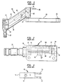
To this end, Figs. 1-7 disclose an extension arm 10 for
mounting a peripheral device in accordance with the prior art.
As shown in Fig. 1, the main elements of the extension arm 10
are a first endcap 12, an upper channel 14, a lower channel
16, a second endcap 18, and a forearm extension 20. The first
endcap 12 has an endcap shaft 22 that is pivotably attachable
to a rigid support mount (not shown), such as an orifice sized
to accept the endcap shaft 22 or a track configured and sized
to engage the grooves on endcap shaft 22. The first endcap 12
is pivotably coupled via pins 24 to both the upper channel 14
and the lower channel 16. The opposite ends of the upper
channel 14 and the lower channel 16 are pivotably coupled via
pins 24 to the second endcap 18. The second endcap 18 is
coupled to the forearm extension 20 via a forearm extension
pin 92. The forearm extension 20 has a vertically disposed
hole 26 therethrough for accepting a device mount (not shown)
such as a tilter, platform or other apparatus.
-
The combination of the upper and the lower channels 14,
1.6 and the first and the second endcaps 12, 18 form an
adjustable parallelogram that permits a device coupled to the
forearm extension 20 to be raised and lowered to a desirable
height. The parallelogram retains its position by employing a
gas spring 28, which is pivotably and adjustably attached to
the first endcap 12 and the upper channel 14, as will be
further described below. Generally, the gas spring 28, e.g.,
a gas type hydraulic cylinder and a retractable piston rod, is
sized so as to have a fixed length until an upward or downward
force is exerted at the second endcap 18 that exceeds the gas
spring's designed resistance. Thus, the gas spring 28 causes
the parallelogram to retain its position when the only force
exerted at the second endcap 18 is the weight of the device,
but permits the parallelogram to be adjusted when a user
pushes the device coupled to the forearm extension 20 up or
down.
-
Fig. 2 illustrates a side view of the first endcap 12,
having the endcap shaft 22 disposed on a first end 30 of the
first endcap 12. To provide a rigid connection between the
two pieces, the endcap shaft 22 is typically machined from
steel and is inserted into the first end 30 during the casting
process of the first endcap 12. The endcap shaft 22 has a
hole 32 formed in an end of the endcap shaft 22 that is
inserted into the first endcap 12. The first endcap 12 is
typically fabricated from cast aluminum. The first endcap 12
also has a second end 34 having a hole 36 disposed
therethrough. Disposed within the first endcap 12 is a
threaded rod 38. A first end 40 of the threaded rod 38 is
inserted into the hole 32 at the base of the endcap shaft 22.
A second end 42 of the threaded rod 38 is aligned with the
hole 36 and is held in place by a clip 44. The clip 44 is
fastened to an inner surface of the first endcap 12 by screws
46.
-
Threadedly mounted on the threaded rod 38 is a clevis 48.
Fig. 3 illustrates a sideview of the clevis 48 including a
tapped hole 50 in the center thereof. The tapped hole 50
receives the threaded rod 38, as shown in Fig. 2. At a first
end of the clevis 48 is a pair of fastening members 52, 54 to
which are fastened one end of the gas spring 28. A second end
56 of the clevis 48 is configured to slidably engage a track
58 which is integrally molded in the first endcap 12 (see Fig.
2). The second end 42 of the threaded rod 38 is configured to
be engaged by a hex-shaped key which is inserted through the
hole 36 when the second end 42 is properly aligned with the
hole 36. The hex-shaped key is employed so as to rotate the
threaded rod 38 along its axis of rotation. When the threaded
rod 38 is rotated along its axis of rotation, the clevis 48
moves along the length of the threaded rod 38 in a direction
that corresponds to the direction which the hex-shaped key is
turned. This movement of the clevis 48 permits the gas spring
28 to be adjusted.
-
Figs. 4(a) and 4(b) illustrate the upper channel 14,
which comprises channel bottom 60 from which extend two
channel sidewalls 62. Channel bottom 60 and sidewalls 62 are
typically stamped from 13 gauge steel sheet in order to give
the upper channel 14 a desired degree of structural rigidity.
At each of the ends of the channel bottom 60, a semi-circular
region 64 of the sidewalls 62 is cut out to accommodate
cold-rolled steel rollers 66, which have a hole 68
therethrough for receiving the pins 24. The rollers 66 are
rigidly attached to the upper channel 14 by MIG welding along
the-edge of the semi-circular cut out region 64 and along the
ends of the channel bottom 60.
-
Additionally, the upper channel 14 comprises stiffener
70, which is welded to an inner surface of the channel bottom
60. Besides providing additional structural rigidity to the
upper channel 14, the stiffener 70 has a hole disposed at one
end with a threaded ball stud 72 placed within the hole and
fixed in place by a nut 74. The ball stud 72 is configured
and sized to receive one end of the gas spring 28. The
longitudinal centerline 76 of the upper channel 14 is
illustrated in Fig. 4(b).
-
Figs. 5(a) and 5(b) illustrate the lower channel 16 which
comprises a channel bottom 78 from which extend two channel
sidewalls 80. As with the upper channel 14, the channel
bottom 78 and sidewalls 80 are typically stamped from 13 gauge
steel sheet, which is relatively heavy in order to give the
lower channel 16 a desired degree of structural rigidity. At
opposite ends of the channel bottom 78, a semi-circular region
82 of the sidewalls 80 is cut out to accommodate cold-rolled
steel rollers 84, which have a hole 86 therethrough for
receiving the pins 24. The rollers 84 are rigidly attached to
the lower channel 16 by MIG welding along the edge of the
semi-circular cut out region 82 and along the ends of the
channel bottom 78. The longitudinal centerline 88 of the lower
channel 16 is illustrated on Fig. 5(b).
-
Fig. 6 illustrates the second endcap 18. Unlike the first
endcap 12, the second endcap 18 does not have an endcap shaft,
nor does it have a clevis assembly for attachment to the gas
spring 28. Instead, the second endcap 18 has a hole 90
disposed in a bottom end for receiving the forearm extension
pin 92, and a hole 94 in a side for inserting a pin 96 into
the forearm extension pin 92, as illustrated in Fig. 1.
-
Fig. 7 illustrates the forearm extension 20 having the
forearm extension pin 92 welded thereto. The forearm
extension pin 92 has a hole 98 formed in an upper end to
receive the pin 96. The forearm extension 20 is configured to
be pivoted around the forearm extension pin 92, and is held in
place within the second endcap 18 by the pin 96 which
penetrates the hole 94 of the second endcap 18 and the hole 98
of the forearm extension pin 92.
-
Extension arms 10 of the prior art, such as the one shown
in Figs. 1-7 and others like it, are ill-suited, for example,
for flat-screen monitors and televisions, in that they are
bulky and cumbersome. Moreover, due to the configuration of
its various parts, extension arms 10 of the prior art cannot
be flattened against a mounting surface so that the entire
extension arm 10 is hidden behind the electronic device when
the device is substantially flush with the mounting surface.
Furthermore, the extension arms 10 of the prior art are not
designed so as to enable the cables to and from a device to be
substantially hidden, and thus protected, within the extension
arm 10 itself. Additionally, the extension arms 10 of the
prior art are generally costly to manufacture and difficult to
assemble.
-
Thus, there is a continued need for an extension arm
suitable to mount an electronic device that enables the cables
to and from the electronic device to be substantially hidden
from view within the extension arm and thus protected from the
elements.
SUMMARY OF THE INVENTION
-
The present invention, in accordance with one embodiment,
relates to an extension arm suitable for mounting an
electronic device, such as a computer monitor, notebook
computers, Internet computers, VCR's, cameras, computer
keyboards, televisions, other electronic devices and the like.
-
In accordance with one embodiment of the present
invention there is described an adjustable extension arm for
mounting an electronic device thereto, the extension arm
characterized by a forearm extension having a first end and a
second end for attachment of a device thereto, the forearm
extension having a first opening at the first end and a second
opening adjacent the second end, the first and second openings
in communication with each other through a channel provided
within the forearm extension between the first and second
ends; a first endcap having a first end rotationally attached
to the first end of the forearm extension, the first endcap
having an opening extending therethrough in communication with
the first opening within the forearm extension; a second
endcap having a first end attachable to a support structure;
elongated first and second channel members nested together to
form a channel therebetween, the first and second channel
members having first ends pivotably attached to the first
endcap and second ends pivotably attached to the second
endcap; and a tilter assembly coupled to the second end of the
forearm extension, the tilter assembly comprising a swivel
bolt having an opening at one end thereof, a swivel lug having
one end pivotably attached to the swivel bolt within the
opening, and an adapter secured to the other end of the swivel
lug.
-
In accordance with another embodiment of the present
invention there is described an adjustable extension arm for
mounting an electronic device thereto, the extension arm
characterized by a forearm extension having an internal
elongated channel opening upward and extending between first
and second ends of the forearm extension; a device mounting
assembly for mounting an electronic device to the second end
of the forearm extension; a first endcap having a first end to
which the first end of the forearm extension is rotationally
mounted, the first endcap including an opening extending
therethrough in communication with the internal elongated
channel within the forearm extension; a second endcap
attachable to a support structure, a nested pair of elongated
members forming an internal elongated channel therein, one
common end of the elongated members pivotably attached to the
first endcap and another common end of the elongated members
pivotably attached to the second endcap, wherein the extension
arm has a cable pathway through the opening extending through
the first endcap and the internal elongated channel within the
forearm extension.
-
In accordance with another embodiment of the present
invention there is described an adjustable extension arm for
mounting an electronic device thereto, the extension arm
characterized by a forearm extension having a first end and a
second end for attachment of an electronic device thereto, the
first end having a through hole connected to the second end by
a U-shaped member having a bottom wall and a pair of spaced
apart sidewalls, the U-shaped member forming an elongated
first channel in communication with the through hole; a cover
releasably attachable to the forearm extension overlying the
through hole and a portion of the U-shaped member for
enclosing the elongated first channel, at least one opening in
the forearm extension in either the bottom wall adjacent the
second end or between the second end and a portion of the
cover; a first endcap including a first end and a second end
having a through hole extending between the first and second
ends; a tubular member received within the through hole within
the first endcap having an interior in communication with the
first channel within the forearm extension, the tubular member
having a sidewall provided with a cutout, the forearm
extension rotatably attached to the first endcap by the
tubular member being received within the through hole within
the first end of the forearm extension; a second endcap having
an end rotatably attachable to a support structure; and
elongated first and second channel members nested together to
form a channel therebetween, the first and second channel
members having first ends pivotably attached to the first
endcap and second ends pivotably attached to the second
endcap, one of the channel members having an elongated opening
between the first and second ends providing communication
between the exterior of the channel member and the channel
formed therein, wherein the extension arm forms a cable
pathway extending through the through hole within the tubular
member and the first channel within the forearm extension.
-
In accordance with another embodiment of the present
invention there is described a tilter assembly for an
electronic device, the assembly characterized by a swivel bolt
having an opening at one end thereof, a swivel lug having one
end pivotably attached to the swivel bolt within the opening,
and an adapter secured to the other end of the swivel lug.
-
In accordance with another embodiment of the present
invention there is described a tilter assembly for electronic
devices, the assembly characterized by a swivel bolt having an
enlarged head at one end thereof and an opening at the other
end thereof formed between a pair of spaced legs, the swivel
bolt including a bore extending from the enlarged head to the
opening formed between the legs, the bore having a threaded
portion; a swivel lug received pivotably within the opening
between the legs, the swivel lug having a top portion
underlying the bore and a distal portion; a resilient member
received within the bore in engagement with the top portion of
the swivel lug; a threaded member rotationally received within
the bore having one end in engagement within the resilient
member, whereby rotation of the threaded member presses the
resilient member against the top portion of the swivel lug to
inhibit the pivotable movement of the swivel lug; an adapter
having an opening within which the distal portion of the
swivel lug is attached; and a device mounting bracket
releasably attachable to the adapter.
-
In accordance with another embodiment of the present
invention there is described a tilter assembly for electronic
devices, the assembly characterized by a swivel bolt having an
enlarged head at one end thereof and an opening at the other
end thereof formed between a pair of spaced legs, the swivel
bolt including a bore extending from the enlarged head to the
opening formed between the legs, the bore having a threaded
portion; a swivel lug received pivotably within the opening
between the legs, the swivel lug having a top portion
underlying the bore and a distal portion; a resilient member
received within the bore in engagement with the top portion of
the swivel lug; a threaded member rotationally received within
the bore having one end in engagement within the resilient
member, whereby rotation of the threaded member presses the
resilient member against the top portion of the swivel lug to
inhibit the pivotable movement of the swivel lug; an adapter
having a T-shaped extension and an opening within which the
distal portion of the swivel lug is attached; and a mounting
bracket releasably attachable to the adapter, the mounting
bracket having a T-shaped opening adapted to receive the T-shaped
extension.
BRIEF DESCRIPTION OF THE DRAWINGS
-
The above description, as well as further objects,
features and advantages of the present invention will be more
fully understood with reference to the following detailed
description of an arm apparatus for mounting electronic
devices with cable management system, when taken in
conjunction with the accompanying drawings, wherein:
- Fig. 1 is an assembly drawing of an extension arm for
mounting a computer monitor, in accordance with the prior art;
- Fig. 2 illustrates a first endcap of an extension arm, in
accordance with the prior art;
- Fig. 3 illustrates the clevis assembly of an extension
arm, in accordance with the prior art;
- Figs. 4a and 4b illustrate the upper channel of an
extension arm, in accordance with the prior art;
- Figs. 5a and 5b illustrate the lower channel of an
extension arm, in accordance with the prior art;
- Fig. 6 illustrates a second endcap of an extension arm,
in accordance with the prior art;
- Fig. 7 illustrates a forearm extension of an extension
arm, in accordance with the prior art;
- Fig. 8 is an exploded assembly drawing of an extension
arm having an interior cable management system for adjustably
mounting a flat-screen device to a support mount, according to
one embodiment of the invention;
- Fig. 9 is a side view of an extension arm with an
interior cable management system;
- Figs. 10a-d illustrate several views of a first endcap,
in accordance with one embodiment of the invention;
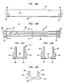
- Figs. 11a-d illustrate several views of an upper channel,
according to one embodiment of the invention;
- Figs. 12a-e illustrate several views of a lower channel,
according to one embodiment of the invention;
- Figs. 13a-c illustrate several views of a partially
enclosed housing of a second endcap, according to one
embodiment of the invention;
- Figs. 14a-b illustrates several views of a shaft assembly
of a second endcap, according to one embodiment of the
invention;
- Fig. 15 illustrates an assembled second endcap according
to one embodiment of the invention;
- Figs. 16a and 16b illustrate a forearm extension, in
accordance with one embodiment of the invention;
- Figs. 17a-b, illustrate several views of a bushing used
in a second female coupling of the extension arm illustrated
in Figs. 16a-b;
- Figs. 18a-b are a side and bottom view of an upper
channel according to one embodiment of the invention;
- Fig. 19 is an assembly drawing of an extension arm for
mounting a device thereto in accordance with one embodiment of
the invention;
- Fig. 20 illustrates a device mounting assembly for
pivotable and rotatable adjustment;
- Fig. 21 illustrates one view of the lower channel
according to one embodiment of the invention;
- Fig. 22 illustrates another view of the lower channel in
accordance with one embodiment of the invention;
- Fig. 23 illustrates a cross-sectional view of the lower
channel taken along line 23-23 in Fig. 21;
- Fig. 24 illustrates one view of a forearm extension
according to one embodiment of the invention;
- Fig. 25 illustrates a cross-sectional view of the forearm
extension taken along line 25-25 in Fig. 24;
- Fig. 26 illustrates one view of a forearm extension cover
member in accordance with one embodiment of the invention;
- Fig. 27 illustrates another view of the forearm extension
cover member according to the invention;
- Figs. 28-30 illustrate several views of an endcap in
accordance with one embodiment of the invention;
- Figs. 31-32 illustrate several views of a tubular member
for assembly in the endcap in accordance with one embodiment
of the invention;
- Fig. 33 illustrates one view of a cover member according
to one embodiment of the invention;
- Fig. 34 is an exploded illustration showing the
components of a tilter constructed in accordance with one
embodiment of the present invention;
- Figs. 35-37 are various illustrations of a swivel bolt
forming a component of the tilter shown in Fig. 34;
- Figs. 38 and 39 are various illustrations of a swivel lug
forming a component of the tilter shown in Fig. 34;
- Figs. 40-43 are various illustrations of a swivel adapter
forming a component of the tilter shown in Fig. 34;
- Fig. 44 illustrates the tilter shown in Fig. 34 in
assembled relationship; and
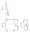
- Figs. 45-47 are various illustrations of a mounting
bracket for the tilter shown in Fig. 34 according to one
embodiment of the invention.
-
DETAILED DESCRIPTION
-
In describing the preferred embodiments of the subject
matter illustrated and to be described with respect to the
drawings, specific terminology will be resorted to for the
sake of clarity. However, the invention is not intended to be
limited to the specific terms so selected, and is to be
understood that each specific term includes all technical
equivalence which operate in a similar manner to accomplish a
similar purpose.
-
With reference to the drawings, in general, and Figs. 8
through 17 in particular, the apparatus of the present
invention is disclosed. Embodiments of an extension arm
suitable for mounting a flat-screen electronic peripheral
device, such as a computer monitor or television, that is
inexpensive and easy to manufacture and assemble, and permits
a flat-screen device to be mounted substantially flush with a
mounting surface is described in WO 00/73027 and U.S. patent
application number no. 09/405,628 filed September 24, 1999
entitled "Arm Apparatus For Mounting Electronic Devices", the
disclosures of which are incorporated herein in their entirety.
The current invention discloses embodiments that enable the
extension arm to substantially hide from view the cables to and
from the flat-screen electronic peripheral device within the
extension arm.
-
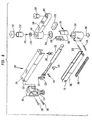
Fig. 8 is an exploded assembly drawing of an extension
arm 100 in accordance with one embodiment. The extension arm
100 comprises a first endcap 102, an upper channel 104, a
lower channel 106, a second endcap 108, and a forearm
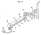
extension 110. Fig. 9 illustrates how cables to and from the
device are disposed within the lower channel 106, the second
endcap 108, and the forearm extension 110 of the extension arm
100 so as to be hidden from view. Fig. 9 will be discussed in
more detail later.
-
Figs. 10a and 10b illustrate the first endcap 102, in
accordance with one embodiment of the invention. In the
embodiment shown, the first endcap 102 includes a partially -
enclosed housing 112 which has flat, oppositely disposed
endwalls 146 and 148 fixedly connected by a sidewall 150. The
sidewall 150 extends partially around the partially enclosed
housing 112 so as to permit manipulation of components to be
assembled within the first endcap 102. In one embodiment, the
endwalls 146 and 148 are semicircular in shape and are
connected along a semicircular edge to the sidewall 150, which
extends perpendicularly therebetween.
-
Fig. 10a illustrates the first endcap 102 having a shaft
114 disposed on the endwall 148. The shaft 114 is preferably
integrally molded to the endwall 148 of the first endcap 102.
Preferably the entire first endcap 102 (the partially enclosed
housing 112 and the shaft 114) is molded from zinc. The
endwall 146 has a hole 152 disposed therethrough. Within the
partially enclosed housing 112 and integrally molded on the
sidewall 150 are stops 156 disposed in proximity to the
endwalls 146, 148; trough walls 158 disposed longitudinally
along the inner surface of the sidewall 150 between the
endwalls 146 and 148 so as to define a trough 160
therebetween; and shelves 162 disposed adjacent to the endwall
148.
-
The stops 156 serve to stop upward or downward movement
of the extension arm 100 when ends of the upper channel 104
and the lower channel 106, respectively, meet the stops 156
when the extension arm 100 is in extended positions. The
trough 160 disposed between the trough walls 158 allows a
clevis 120 to be moved therein, as discussed in more detail
later. Fig. 10b illustrates the shelves 162 defining coplanar
faces separated by a groove 164. The shelves 162 have a
connection means, such as self tapping screw holes 154
disposed therein. The coplanar faces of the shelves 162 are
configured to engage a retainer clip 126, which is fastened in
place by, for example, a pair of screws 128. When the
retainer clip 126 is fastened in place, the groove 164 defines
a spacing for accepting one end of a threaded rod 124, as
discussed in more detail below.
-
The threaded rod 124 and the clevis 120 are now
fabricated and assembled in the first endcap 102. The
threaded rod 124 is employed within the first endcap 102 so as
to adjustably support the clevis 120. Fig. 10c illustrates
the threaded rod 124 having a first end 166 which has a
circular cross-section within which is axially disposed a
shaped opening 168, for example a hex-shaped opening, for
accepting a shaped key (not shown), such as a hex-shaped key.
Advantageously, a cross-sectional diameter of the first end
166 is smaller than a cross-sectional diameter of the hole
152, so as to be inserted therein. Adjacent the first end 166
is a shoulder 170. Advantageously, the shoulder 170 has a
circular cross-section having a diameter that is larger than
the cross-sectional diameter of the hole 152. Thus, in a
preferred embodiment, the shoulder 170 abuts an inner surface
of the endwall 146 and retains the first end 166 within the
hole 152.
-
The threaded rod 124 also includes a threaded section 172
which is configured to threadingly engage the clevis 120. A
second end 174 of threaded rod 124 is disposed in the groove
164 located between the shelves 162 of the first endcap 102.
Preferably, the second end 174 of the threaded rod 124 has a
circular cross-section having a diameter that is smaller than
the size of the groove 164, such that the second end 174 is
supported between the shelves 162 but is free to rotate
therein.
-
As previously mentioned, threadedly mounted on the rod
124 is the clevis 120. The clevis 120 as illustrated in Fig.
10d, has a tapped hole 176 formed therein for receiving the
threaded rod 124. The clevis 120 also has a pair of fastening
members 178 at a first end to which are fastened a first end
of a gas spring 122. The second end of the clevis 120 is
configured to slidably engage the trough 160.
-
When the first end 166 of the threaded rod 124 is engaged
by a shaped key, the shaped key is employed so as to rotate
the threaded rod 124 around its axial centerline. When the
threaded rod 124 is rotated around this axis of rotation, the
clevis 120 moves along the length of the threaded rod 124 in a
direction that corresponds to the direction which the shaped
key is turned. This movement of the clevis 120 permits the
gas spring 122 to be adjusted.
-
The partially enclosed housing 112 is configured with,
for example, holes 116 to receive a connection mechanism, such
as pins 118, therethrough. The shaft 114 is configured to be
inserted for pivotable rotation in a support mount (not
shown), which may be a wall, desk or pole mount, or a
configurable mount as shown and described in WO 00/25640 and
Applicant's co-pending U.S. patent application no. 09/406,531
entitled "Configurable Mount" filed on September 27, 1999, the
disclosures of which are incorporated herein by reference in
their entirety.
-
Figs. 11a-d illustrate several views of the upper channel
104, according to one embodiment of the invention. The upper
channel 104 includes a U-shaped body 130 and integrally cast
rollers 132 disposed at opposite ends of the U-shaped body
130. The U-shaped body 130 comprises a channel bottom 180
from which extend two channel sidewalls 182. The channel
bottom 180, the sidewalls 182 and the rollers 132 of the upper
channel 104 are preferably integrally cast from zinc, which
gives the upper channel 104 a lesser weight, and a degree of
structural rigidity, more suitable for lighter-weight
flat-screen devices than the prior art upper channel 14 which
is stamped from heavy gauge steel. The rollers 132 have a
hole 184 therethrough (either cast or subsequently drilled)
for receiving a connection mechanism, such as the pins 118.
Additionally, the upper channel 104 comprises a threaded hole
186 configured and sized to receive a threaded end of a ball
stud 138. The threaded hole 186 is also integrally cast. The
ball stud 138 is configured and sized to receive a second end
of the gas spring 122.
-
Unlike the prior art upper channel 14 in which the
U-shaped channel is formed by heating a piece of steel and
bending the steel to form the channel bottom 60 and the
sidewalls 62, the upper channel 104 of the invention is cast
molded. The use of cast molding ensures the angle between the
channel bottom 180 and the sidewalls 182 is exactly the same
each and every time. Moreover, cast molding enables the
sidewalls 182 to be tapered. As illustrated in Figs. 11c and
11d, both an outer surface and an inner surface of the
sidewalls 182 may taper in, for example, by approximately 1
degree. It should be noted that the taper is not limited to 1
degree, and that the taper of the inner surface and the outer
surface need not be the same. The taper provides several
advantages including more clearance between the upper and the
lower channels 104, 106 when the upper and the lower channels
104, 106 are brought together during usage. That is, the
inner surface of the sidewalls 182 being displaced by 1 degree
means that there will be additional clearance for the lower
channel 106 to fit therewithin. The additional clearance will
help prevent the upper channel 104 and the lower channel 106
from scraping together.
-
Figs. 12a-e illustrate several views of the lower channel
106, according to one embodiment of the invention. The lower
channel 106 includes a U-shaped body 134 and integrally cast
rollers 136 disposed at opposite ends of the U-shaped body
134. The U-shaped body 134 of the lower channel 106 comprises
a channel bottom 190 from which extend two channel sidewalls
192. The channel bottom 190, the sidewalls 192 and the
rollers 136 of the lower channel 106 are preferably integrally
cast from zinc, which gives the lower channel 106 a lesser
weight when compared to heavy gauge steel, and a degree of
structural rigidity, more suitable for lighter-weight
flat-screen devices. The rollers 136 have a hole 194
therethrough (either cast or subsequently drilled) for
receiving a connection mechanism, such as the pins 118.
-
The channel bottom 190 additionally includes a cable
channel 196 running longitudinally therealong. In the
embodiment shown, a first end 197 of the cable channel 196
starts near an end of the channel bottom 190 that pivotably
connects to the first endcap 102. The cable channel 196 then
runs along the entire length of the channel bottom 190 to the
end of the channel bottom 190 that pivotably connects to the
second endcap 108. Thus, the second end 199, of the cable
channel 196 is an opening between the roller 136 at the end of
the channel bottom that pivotably connects to the second
endcap 108. The first end 197 may be, for example, rounded to
improve the rigidity of the lower channel 106. The cable
channel 196 is configured to receive a cable cover 198
(illustrated in Fig. 12e) which is configured to removably fit
within the cable channel 196. Thus, cables of the mounted
device may be substantially retained within the lower channel
106 so as to hide them from view and protect them from harm.
The cable channel 196 and the cable cover 198 enable cables to
be accessed when desired, while securing them within the lower
channel 106.
-
As illustrated in Figs. 12c and 12d the sidewalls 192 of
the lower channel 106 are tapered. For example, an outer
surface of the sidewalls 192 may be tapered approximately 112
degree while an inner surface may be tapered approximately 1
degree. It should be noted that the taper is not limited to a
particular angle, and that the taper of the inner surface and
the outer surface may be the same. The taper is possible
because the lower channel 106 is, in the preferred embodiment,
cast molded. As noted above with respect to the upper channel
104, the taper provides more clearance between the upper
channel 104 and the lower channel 106 so as to reduce or
eliminate the chance of the upper and the lower channels 104,
106 scraping.
-
As illustrated in Fig. 12e, the cable cover 198 includes
a top cover 202 with two sidewalls 204 protruding therefrom.
A far end of each sidewall 204 has a catch 206 formed thereon
so as to engage with the cable channel 196.
-
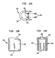
The second endcap 108 includes a partially enclosed
housing 250 and a shaft assembly 252. As illustrated in Figs.
13a-c, the partially enclosed housing 250 has a first endwall
254 and a second endwall 256 oppositely disposed from each
other and fixedly connected by a sidewall 258. The sidewall
258 extends partially around the partially enclosed housing
250 so as to permit manipulation of components, such as
cables, which may be contained therewithin. The first endwall
254 has a hole 260 disposed therethrough and threaded holes
262 disposed therein that are in communication with the hole
260. Disposed with the threaded holes 262 are set screws 264.
Preferably, the diameter of the hole 260 is large enough to
allow a plug end of a cable to fit therethrough.
-
As illustrated in Figs. 14a-c, the shaft assembly 252
preferably includes two symmetrical endcap adapters 266 which
when assembled provide a hollow shaft 268. The endcap
adapters 266 have a mounting end 270 and a shaft end 272 that
is thinner than the mounting end 270. As illustrated in Fig.
15, the mounting end 270 of both of the endcap adapters 266
are inserted into the hole 260 and are coupled together and to
the partially enclosed housing 250, to form the second endcap
108, by tightening the set screws 264.
-
The upper and the lower channels 104, 106 and the first
and the second endcaps 102, 108 are configured so as to form
an adjustable parallelogram. When configured, the shaft 114
of the first endcap 102 and the hollow shaft 268 of the second
endcap 108 point in opposite directions. For example, as
illustrated in Fig. 8, the shaft 114 of the first endcap 102
extends vertically downward while the hollow shaft 268 of the
second endcap 108 extends vertically upward. The shape of the
parallelogram is retained by the gas spring 122. As
previously mentioned, the first end of the gas spring 122 is
attached to the ball stud 138 mounted within the upper channel
104 and the second end is adjustably mounted to the clevis 120
within the first endcap 102.
-
Generally, the gas spring 122 is sized so as to have a
fixed length until an upward or downward force is exerted at
the second endcap 108 that exceeds the gas spring's designed
resistance. Thus, the gas spring 122 retains the
parallelogram shape when the only force exerted at the second
endcap 108 is the weight of the flat-screen device. However,
the gas spring 122 permits the parallelogram shape to be
adjusted when a user pushes the flat-screen device coupled to
the forearm extension 110 up or down.
-
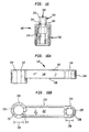
With reference to Figs. 16a and 16b, the forearm
extension 110 includes a body 140 having a first female
coupling 142 located on a first end and a second female
coupling 144 located on a second end. The first female
coupling 142 has an inner diameter 209 that is sized to
rotatably engage the hollow shaft 268 of the second endcap
108. The first female coupling 142 is also configured to
receive a cable through the hollow shaft 268. That is, the
first female coupling 142 has a cable slot 274 formed therein,
for example by milling the cable slot 274 into the first
female coupling 142, or by casting the first female coupling
142 with the cable slot 274 integrally formed therein.
-
The first female coupling 142 preferably has a set screw
212 formed within a wall 214 thereof. The set screw 212 can
be tightened to prevent the first female coupling 142 from
rotating about the hollow shaft 268. Advantageously, the
first female coupling 142 has a plurality of voids 217 formed
in the wall 214, which saves on material costs and permits the
forearm extension 110, when cast, to be cooled more quickly.
The quicker cooling enables the production quantity to be
increased.
-
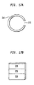
A bushing 210 (Fig. 8) is preferably used to engage the
first female coupling 142 and the hollow shaft 268. That is,
the bushing 210 is placed over the hollow shaft 268 and within
the first female coupling 142. The bushing 210 is preferably
made of a smooth material, such as plastic, in order to reduce
friction and prevent metal to metal contact. As illustrated
in Figs. 17a and 17b, the bushing 210 also has a cable slot
276 formed therein. The cable slots 274, 276 are aligned so
that a cable can pass therethrough. When the set screw 212 is
tightened it causes the bushing 210 to flex inward and
frictionally engage the hollow shaft 268 and thus prevent the
forearm extension 110 from rotating about the hollow shaft
268. The hollow shaft 268 and the first female coupling 142
are held together by utilizing a screw 211 and a washer 213
(Fig. 8).
-
The body 140 preferably has an inverted U-shape with a
topwall 207 and two sidewalls 208 so that a cable can be
hidden therein. Advantageously attached within the U-shaped
body 140, and preferably on the topwall 207, is a cable holder
278 (Fig. 8). The cable holder 278 secures a cable within the
U-shaped body so that it can be hidden from view as it travels
the length of the forearm extension 110.
-
The second female coupling 144 is for attachment to a
device mounting (not shown), such as a tilter described in
WO 00/73024 and Applicant's co-pending patent application no.
09/406,530 filed on September 27, 1999 which are incorporated
herein by reference in their entirety, a platform, or other means
for supporting a flat-screen device. Thus, the second female
coupling 144 has an inner diameter 218 that is sized to
rotatably engage a shaft of the device mount. A bushing 220
(Fig. 8), preferably made of a smooth material such as
plastic, is placed over the shaft and within the second female
coupling 144. The second female coupling 144 preferably has a
set screw 222 formed within a wall 224 of the second female
coupling 144. When the set screw 222 is tightened it causes
the bushing 220 to flex inward and frictionally engage the
shaft and thus prevent the device mount from rotating around
the second female coupling 144. Advantageously, the second
female coupling 144 also has a plurality of voids 226 formed
in the wall 224.
-
The embodiment of the forearm extension 110 illustrated
in Figs. 16a and 16b, has the topwall 207 flush with an upper
edge of the female couplings 142, 144. Since the first female
coupling 142 is larger than the second female coupling, the
center of the first female coupling 142 is not aligned with
the center of the second female coupling 144 or an axial
centerline 228 of the body 140. It should be noted that an
alternative embodiment is to have the center of the female
couplings 142, 144 and the axial centerline 228 of the body
140 all aligned, so that the topwall 207 would not be aligned
with an upper edge of the first female coupling 142.
-
The embodiment illustrated in Fig. 16a, has the body 140
horizontally disposed between the female couplings 142, 144
when the axial centerlines of the female couplings 142, 144
are vertically disposed. It should be noted however that the
body 140 is not limited to be horizontally disposed and may be
disposed at an incline in this embodiment.
-
The present invention permits a flat-screen device which
is mounted to a wall to be flattened against the wall while
hiding the extension arm 100 within the shadow of the device.
That is, the forearm extension 110 may be folded into a
position which is directly above the upper and the lower
channels 104, 106. As a result, the mounted device is flush
to the mounting surface and substantially hides the
parallelogram, formed by the first and the second endcaps 102,
108 and the upper and the lower channels 104, 106, as well as
the forearm extension 110 from view. Thus, the aesthetic
appeal of the extension arm 100 is increased and the space
occupied by the extension arm 100 and the device is minimized.
-
Referring back to Fig. 9, a flat-screen monitor 300 is
attached to a tilter 302 which is rotatably coupled to the
second female coupling 144. A cable 304, such as a power
cable, proceeds from the monitor 300 to the underside off the
U-shaped body 140 of the forearm extension 110. The cable 304
is held in place within the U-shaped body 140 by the cable
holder 278. The cable 304 proceeds from the body through the
cable slots 274, 276 in the bushing 210 and the first female
coupling 142. The cable then proceeds through the hollow
shaft 268 of the second endcap 108. The cable exits the
second endcap 208 through the open end of the partially
enclosed housing 260. The cable proceeds down the length of
the lower channel 106 and exits at the first end 197 of the
cable channel 196.
-
Preferably, the cable 304 is inserted into the extension
arm 100 as portions of the extension arm 100 are being
assembled. That is, the cable 304 is placed under the
U-shaped body 140 of the forearm extension 110 and is held in
place by the cable holder 278. The cable is then passed
through the cable slots 274, 276. The cable 304 including the
plug 306 is then fed through the hole 260 in the second endcap
108. The second endcap 108 is now assembled by inserting the
mounting end 270 of each endcap adapter 268 into the hole 260,
thus surrounding the cable 304. The endcap adapters 268 are
held together and within the hole 260 by tightening the set
screws 264. The hollow shaft 268 is then placed within the
first female coupling 142. The cable 304 is placed within the
lower channel 106, prior to the lower channel 106 and the
second endcap being secured together. This ensures that the
cable 304 is above the roller 136 and is contained within the
hollow bar formed by the upper channel 104 and the lower
channel 106.
-
Referring back to Fig. 8, several additional components
of the extension arm 100 are discussed. For aesthetic
purposes, a bumper 280 may be placed on the second endwall 256
of the second endcap 108 and a plug 282 may be placed over the
first female coupling 142. A washer 284 may be placed over
the two endcap, adapters 268 to help secure them together.
-
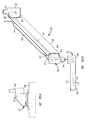
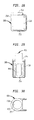
Referring to Figs. 18a-b, the upper channel 104 is
constructed to optionally include internal reinforcements.
This is particularly advantageous when mounting heavy
electronic devices to the extension arm, for example, large
computer monitors of the CRT type. Internal within the upper
channel 104 is a rib assembly including a plurality of cross-ribs
400 and angularly disposed secondary ribs 402. By way of
example, the cross-ribs 400 are disposed transverse to the
sidewalls 182, while the secondary ribs 402 are disposed at an
angle so as to form a triangular internal support structure.
The cross-ribs 400 and secondary ribs 402 may be formed as an
integral member which can be inserted into the upper channel
104. Preferably, the cross-ribs 400 and secondary ribs 402
are integrally cast during formation of the upper channel 104.
-
Referring to Fig. 19, there is illustrated an extension
arm 404 constructed in accordance with another embodiment of
the present invention, wherein like reference numerals
represent like elements with respect to the extension arm 100
shown in Figs. 8 and 9. Generally as shown, the extension arm
404 includes a first endcap 102, nested upper and lower
channels 104, 106, a second endcap 108 and a forearm extension
110. Briefly, as thus far described with reference to
extension arm 100, the first endcap 102 is mountable to a
support structure such as, by way of example, endcap shaft
114. The shaft 114 is configured to be inserted for pivotable
rotation to a support mount (not shown), such as previously
discussed and as disclosed in Applicant's co-pending U.S. patent
application no. 09/406,531 and WO 00/25640.
-
The upper and lower channels 104, 106 are nested together
to permit relative sliding movement therebetween in both
longitudinal and transverse direction. The upper and lower
channels 104, 106 by virtue of their general U-shaped
construction form therebetween an internal channel extending
therethrough. The common ends of the upper and lower channels
104, 106 are pivotably attached to the first endcap 102 by
means of pins 118 as previously described. Similarly, the
other common ends of the upper and lower channels 104, 106 are
pivotably attached to the second endcap 108 by means of pins
118. A gas spring 122 of the hydraulic type is received
within the channel formed between the upper and lower channels
104, 106 and attached to the clevis 120 and upper channel 104
as previously described. The forearm extension 110 is
rotatably mounted to the second endcap 108 about a hollow
tubular member 406 as to be described hereinafter.
-
As shown in Fig. 20, an electronic device 408 is attached
to a tilter 302. The tilter, via its shaft 410 is rotatably
mountable to the free end of the forearm extension 410. The
tilter 302 includes a shaft 412 about which the electronic
device 408 can be pivoted. As such, the tilter 302 enables
the rotation and pivoting or tilting of the electronic device
408 into a desired orientation. One such tilter 302 is
described and disclosed in WO 00/73024 and Applicant's co-pending
U.S. patent application no. 09/406,530 filed on September 27, 1999,
the disclosures of which are incorporated herein by reference.
-
Turning to Figs. 21-23, there is illustrated the
construction of the lower channel 106 in accordance with one
embodiment of the invention. It is to be understood that the
lower channel 106 is generally of similar construction as thus
far described. In this regard, the lower channel 106 includes
a U-shaped body having rollers 136 disposed at opposite ends.
In accordance with the preferred embodiment, the rollers 136
are integrally cast in forming the lower channel 106. The
lower channel includes a channel bottom 190 from which extends
two channel sidewalls 192. The rollers 136 have a hole 194
therethrough for receiving a connection mechanism such as the
pins 118.
-
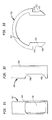
The channel bottom 190 additionally includes a cable
channel 196 running longitudinally therealong. In the
embodiment shown, the cable channel 196 extends along the
length of the channel bottom 190, terminating inwardly and
adjacent the rollers 136. One or both of the ends of the
cable channel 136 may be rounded or having a key-hole shape.
The cable channel 196 is configured to receive a cable cover
412 as shown in Fig. 33. Thus, cables 304 of the mounted
electronic device 408 may be wholly or partially retained
within the lower channel 106 so as to hide them from view and
protect them from harm. Where the cables 304 are placed
externally of the lower channels 106, they are covered and
protected by the cable cover 412.
-
As shown in Fig. 33, the cable cover is formed as an
elongated U-shaped body having spaced apart legs 414, 416.
The ends of the legs 414, 416 are provided with an outwardly
extending bump 418 which forms a side recess 420. The cable
cover 412 is removably attached to the lower channel 106 by
inserting the legs 414, 416 through the cable channel 196.
The edges of the channel bottom 190 will be received within
the side recesses 420 after the legs 414, 416 are deflected
inwardly by engagement with the bumps 418.
-
The cable cover 412 forms an elongated opening 422
overlying the cable channel 196. It is contemplated that in
certain applications, a cable 304 may be strung through the
interior of the lower channel 106 when assembling the
extension arm 404. In certain other applications, the
construction of the lower channel 106 and gas spring 120 will
limit the space within the lower channel for accommodating a
cable 304. In this regard, the cable channel 196 and opposing
opening 422 will provide additional space for receiving the
cable. Further in this regard, in an application where the
extension arm 404 is fully assembled, it might not be possible
to thread a cable through the lower channel 106. As such, the
cable 304 can be extended overlying the cable channel 196 and
contained within the opening 422 of the cable cover 412. It
is also further contemplated that the cable 304 can be
threaded through the interior of the lower channel 106 and
directly into the interior of the second endcap 108 or
outwardly through the cable channel 196. This is particularly
facilitated when installing cable 304 during the assembly of
the extension arm 404 as to be described hereinafter.
-
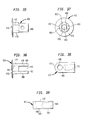
Figs. 24 and 25 illustrate the construction of a
modification of the forearm 110 as shown in Figs. 16a and 16b.
The forearm extension 110, as modified, includes a bottom wall
424 which extends from the first female coupling 142 to the
second female coupling 144. In accordance with one
embodiment, the bottom wall 424 is provided with an opening
426 arranged adjacent the second female coupling 144. The
forearm extension 110 is provided with an open top forming an
opening 428 extending from the first female coupling 142 to
the second female coupling 144 and over the opening 426 in the
bottom wall 424.
-
The opening 424 which extends through the forearm
extension 110 is wholly or partially closed by a removable
cable cover 430 as shown in Figs. 26 and 27. The cable cover
430 includes a top wall 432 from which there depends a
plurality of ribs 434 of different length and height. The
topwall 432 of the cable cover 430 is formed from an elongated
section 436 and a circular section 438. The circular section
438 is adapted to be disposed over the female coupling 142,
while the elongated section 436 is adapted to be received over
the adjacent portion of the forearm extension 110. The ribs
extend inwardly into the opening 428 and are sized so as to
engage the sidewalls forming the forearm extension 110 and
first female coupling 142. The friction fit effected by the
ribs 434 maintains the cable cover 430 in position overlying
the opening 428. The cable cover 430 has an end 440 which as
shown is a semicircular section. However, it is to be
understood that the end 440 may be straight or other shaped.
The end 440, when the cable cover 430 is in position,
terminates short of the location of the second female coupling
142 as shown in Fig. 19. As a result, an opening 442 is
provided between the end 440 of the cable cover 430 and the
second female coupling 144. It is not a requirement that
opening 442 be overlying or in alignment with opening 426 in
the bottom wall 424.
-
The forearm extension 110 is pivotably mounted to the
second endcap 108 by rotationally receiving therein the free
end of the tubular member 406 as shown in Fig. 19. Referring
to Figs. 31 and 32, the tubular member 406 is constructed from
an elongated cylindrical body 444 having a hollow interior
446. A generally rectangular-shaped opening 448 is cut into
the sidewall of the body 444 to provide communication to the
hollow interior 446.
-
As shown in Figs. 28-30, the second endcap 108 includes a
partially enclosed housing including spaced apart first and
second endwalls 254, 256 connected by sidewall 258. The
sidewall 258 extends partially around the housing so as to
form a cylindrical through hole 450 extending between the
first and second endwalls 254, 256. The construction of the
second endcap 108 is similar to that described with respect to
the endcap shown in Figs. 13a-13c.
-
The tubular member 406 is inserted into the opening 450
within the second endcap 108 as shown in Fig. 29. The
rectangular opening 448 is aligned to allow access into the
interior of the tubular member for feeding cable 304
therethrough.
-
Referring once again to Fig. 19, the cable 304 is
concealed by passing through the interior of the second endcap
108. The cable 304 may extend into the interior of the second
endcap 108 from either of two locations. For example, the
cable 304 may run along the exterior of the lower channel
member 106, being enclosed by cable cover 412. In this
regard, all or a portion of the cable 304 may also be received
within the interior of the lower channel 106 through the cable
channel 196 therein. The cable 304 will then extend into the
second endcap 108 through the opening in the second endwall
256. In addition, the cable 304 may extend wholly or
partially within the lower channel 106, entering the second
endcap 104 directly through the opening 448 in the tubular
member 406.
-
The cable 304 extends into the interior of the forearm
extension 110 through the first female coupling 142 to a
location adjacent the free end where the tilter 302 is
rotationally supported. The cable 304 exits from the forearm
extension 110 through either of the openings 426, 442. The
openings 426, 444 and the tubular member 406 are sized to
allow the pin connector attached to the cable 304 for the
electronic device to pass therethrough. The extension arms
100, 404 as thus far described provide a construction for the
internal management of cables 304 to and from a support
electronic device 408.
-
Turning now to Figs. 34-47, there will be described a
tilter 458 constructed in accordance with another embodiment
of the present invention. As shown in Fig. 34, the tilter 458
includes a swivel bolt 460, a swivel lug 462, a dowel pin 464,
a friction pellet 466, a set screw 468, an adapter 470, bolt
472, and optionally a mounting sleeve 474. In addition to the
foregoing components, and as shown in Figs. 45-47, there is
provided an adapter mounting bracket 475.
-
Turning to Figs. 35-37, the swivel bolt 460 includes a
top plate 476 which may be circular, rectangular, oval or any
other shape as desired. Depending from the top plate 476 is a
generally cylindrical body 478 having an upper portion
provided with a threaded hole 480 and a lower portion provided
with a rectangular cutout 482 which defines a pair of spaced
apart legs 484, 486. The cutout 482 is in communication with
the end of the threaded hole 480 which defines a receiving
space for receiving a portion of the swivel lug 462. A hole
488 is arranged transversely through the legs 484, 486 in
alignment with each other. As shown in Fig. 37, the legs 484,
486 are generally provided with flat planar parallel spaced
apart inner surfaces 490 and outer curved surfaces 492.
-
As shown in Figs. 38 and 39, the swivel lug 462 is formed
from a rectangular body 494 having a rounded upper end 496. A
through hole 498 extends through the swivel lug 462 adjacent
the upper end 496. The other end of the swivel lug 462 is
provided with a threaded hole 500 which extends to a location
adjacent the through hole 498. The threaded hole 500 is
preferably not in communication with the through hole 498.
The swivel lug 462, as shown in Fig. 39, is formed with a pair
of spaced apart parallel planar surfaces 502, 504.
-
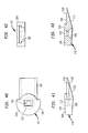
Turning to Figs. 40-43, the adapter 470 includes a main
body section 504 and a T-shaped extension 506. The main body
section 504 includes a through opening 508. The through
opening 508 adjacent the top surface 510 of the main body
section 504 is provided as a rectangular-shaped opening 512.
As best shown in Fig. 40, the rectangular-shaped opening 512
is of greater size than the adjacent portion of the through
opening 508. The T-shaped extension 506 extends outwardly
from the main body section 504. As best shown in Figs. 41 and
43, the T-shaped extension 506 has a generally horizontal
topwall 514 and a sloped bottom wall 516 providing a wedge-shaped
profile.
-
Referring to Figs. 34 and 44, the assembly of the tilter
458 will now be described. The swivel lug 462 is inserted
into the rectangular cutout 482 defined between legs 484, 486
of the swivel bolt 460. The upper end 496 is positioned
adjacent and underlying the threaded hole 480. The swivel lug
462 is pivotably mounted to the swivel bolt 460 by inserting
the cylindrical dowel pin 464 through the aligned holes 488,
498 in the swivel bolt and swivel lug. As shown in Fig. 44,
this permits the swivel lug 462 to pivot about the dowel pin
464 into and out of the plane of the figure.
-
The friction pellet 466 is inserted into the bottom end
of the threaded hole 480 in the swivel bolt 460 where it is
supported by its engagement with the upper end 496 of the
swivel lug 462. The threaded set screw 468 is inserted into
the threaded hole 480 such that its end is in engagement with
the upper surface of the friction pellet 466. Rotation of the
set screw 468 will apply pressure on the friction pellet 466
which, in turn, will apply pressure to the swivel lug 462.
The friction pellet 466 is preferably constructed of a polymer
material so as to be resilient and capable of withstanding the
forces imparted by the set screw 468. Upon applying
sufficient force, the pivotable action of the swivel lug 462
may be arrested for adjustment purposes as to be described
hereinafter.
-
The assembly as thus far described, i.e., the swivel bolt
460 and swivel lug 462, may be inserted into an adapter
receiving support 474. As shown in Fig. 34, the adapter
receiving support 474 is in the nature of a hollow cylindrical
body having a generally planar flanged top 520. The
cylindrical body 518 forms a cylindrical through hole 522
having a size and shape adapted to receive the body 478 of the
swivel bolt 460. The length of the cylindrical body 518
allows a portion of the swivel lug 562 to extend outwardly
therebeyond as shown in Fig. 44. The tilter 458 has been
described thus far as including an adapter receiving support
474. The adapter receiving support 474 can be inserted into
the opening 212 within the end of the forearm extension 110.
However, it is to be understood that the adapter receiving
support 474 may be eliminated. In this regard, the swivel
bolt 460 will be inserted directly into the opening 218. As
such, the adapter receiving support 474 can function as a
liner or bearing for the opening 218 and can therefore be
constructed from a variety of materials such as polymer
materials, as well as metal if so desired.
-
The free end of the swivel lug 462 is inserted into the
rectangular-shaped opening 512 within the adapter 470. The
swivel lug 462 is secured thereat by threaded bolt 472 which
is threaded into the threaded hole 500 of the swivel lug. The
completed assembly of the tilter 458 is shown in Fig. 44. The
adapter 470 is operative for rotation about the longitudinal
axis of the swivel bolt 460. In this regard, the swivel bolt
460 will rotate within the adapter receiving support 474. To
this end, it is preferable that the adapter receiving support
474 be constructed of polymer materials. In addition, the
adapter 470 may be pivoted about the axis of the dowel pin 464
by means of the swivel lug 462. Accordingly, the adapter 470
can be both pivoted and rotated as desired.
-
The adapter 470 is releasably attached to a device
mounting bracket 475. As shown in Figs. 45-47, the mounting
bracket 475 includes a plate 526 having a plurality of through
holes 528. The through holes 528 may be arranged at various
locations as desired. As shown in Fig. 47, the through holes
528 can be used for attaching the plate 526 to the rear
surface of an electronic device 408, such as an LCD monitor,
etc. Other attachment mechanisms such as screws, clamps may
be used for attaching the plate 526 to the desired electronic
device 408.
-
The plate 526 is provided at one end with a configured
wall 530 which defines a T-shaped opening 532. The T-shaped
opening 532 is sized and configured so as to receive the T-shaped
extension 506 on the adapter 470. As shown in Fig. 44,
the T-shaped extension 470 can be inserted into the T-shaped
opening 532 and secured thereat by means of a bolt or set
screw 534. In this manner, the electronic device 408 will be
connected to the tilter 458 via the mounting bracket 475 to
enable its rotation and pivoting or tilting as thus far
described. The tilting orientation of the mounting bracket
475 can be fixed by tightening the set screw 468 to apply a
sufficient force against the swivel lug 462 by means of the
friction pellet 466.
-
Although the invention herein has been described with
reference to particular embodiments, it is to be understood
that these embodiments are merely illustrative of the
principles and applications of the present invention. It is
therefore to be understood that numerous modifications may be
made to the illustrative embodiments and that other
arrangements may be devised without departing from the spirit
and scope of the present invention as defined by the appended
claims.