EP1223562A1 - Coin counting and sorting device - Google Patents
Coin counting and sorting device Download PDFInfo
- Publication number
- EP1223562A1 EP1223562A1 EP00942446A EP00942446A EP1223562A1 EP 1223562 A1 EP1223562 A1 EP 1223562A1 EP 00942446 A EP00942446 A EP 00942446A EP 00942446 A EP00942446 A EP 00942446A EP 1223562 A1 EP1223562 A1 EP 1223562A1
- Authority
- EP
- European Patent Office
- Prior art keywords
- token
- tokens
- transfer
- rotary disc
- sorting
- Prior art date
- Legal status (The legal status is an assumption and is not a legal conclusion. Google has not performed a legal analysis and makes no representation as to the accuracy of the status listed.)
- Granted
Links
- 238000011144 upstream manufacturing Methods 0.000 claims abstract description 20
- 238000003825 pressing Methods 0.000 claims abstract description 9
- 238000001514 detection method Methods 0.000 claims description 25
- 230000005540 biological transmission Effects 0.000 claims description 16
- 238000003860 storage Methods 0.000 claims description 15
- 238000005299 abrasion Methods 0.000 description 14
- 238000005192 partition Methods 0.000 description 10
- 238000004519 manufacturing process Methods 0.000 description 5
- 229910052751 metal Inorganic materials 0.000 description 4
- 239000002184 metal Substances 0.000 description 4
- 229920003002 synthetic resin Polymers 0.000 description 4
- 239000000057 synthetic resin Substances 0.000 description 4
- 230000002093 peripheral effect Effects 0.000 description 3
- PXHVJJICTQNCMI-UHFFFAOYSA-N Nickel Chemical compound [Ni] PXHVJJICTQNCMI-UHFFFAOYSA-N 0.000 description 2
- 230000003247 decreasing effect Effects 0.000 description 2
- 239000000835 fiber Substances 0.000 description 2
- 230000006698 induction Effects 0.000 description 2
- RYGMFSIKBFXOCR-UHFFFAOYSA-N Copper Chemical compound [Cu] RYGMFSIKBFXOCR-UHFFFAOYSA-N 0.000 description 1
- 229910000570 Cupronickel Inorganic materials 0.000 description 1
- 229910000831 Steel Inorganic materials 0.000 description 1
- 229910052782 aluminium Inorganic materials 0.000 description 1
- XAGFODPZIPBFFR-UHFFFAOYSA-N aluminium Chemical compound [Al] XAGFODPZIPBFFR-UHFFFAOYSA-N 0.000 description 1
- 238000006243 chemical reaction Methods 0.000 description 1
- -1 copper Chemical class 0.000 description 1
- 229910052802 copper Inorganic materials 0.000 description 1
- 239000010949 copper Substances 0.000 description 1
- 238000002788 crimping Methods 0.000 description 1
- 238000005520 cutting process Methods 0.000 description 1
- 230000007423 decrease Effects 0.000 description 1
- 238000010586 diagram Methods 0.000 description 1
- 238000007599 discharging Methods 0.000 description 1
- 239000013013 elastic material Substances 0.000 description 1
- 238000003384 imaging method Methods 0.000 description 1
- 238000003754 machining Methods 0.000 description 1
- 239000000463 material Substances 0.000 description 1
- 150000002739 metals Chemical class 0.000 description 1
- 229910052759 nickel Inorganic materials 0.000 description 1
- 239000013307 optical fiber Substances 0.000 description 1
- 230000000149 penetrating effect Effects 0.000 description 1
- 230000008054 signal transmission Effects 0.000 description 1
- 239000010959 steel Substances 0.000 description 1
- 239000013585 weight reducing agent Substances 0.000 description 1
Images


Classifications
-
- G—PHYSICS
- G07—CHECKING-DEVICES
- G07D—HANDLING OF COINS OR VALUABLE PAPERS, e.g. TESTING, SORTING BY DENOMINATIONS, COUNTING, DISPENSING, CHANGING OR DEPOSITING
- G07D3/00—Sorting a mixed bulk of coins into denominations
- G07D3/02—Sorting coins by means of graded apertures
- G07D3/06—Sorting coins by means of graded apertures arranged along a circular path
-
- G—PHYSICS
- G07—CHECKING-DEVICES
- G07D—HANDLING OF COINS OR VALUABLE PAPERS, e.g. TESTING, SORTING BY DENOMINATIONS, COUNTING, DISPENSING, CHANGING OR DEPOSITING
- G07D3/00—Sorting a mixed bulk of coins into denominations
- G07D3/16—Sorting a mixed bulk of coins into denominations in combination with coin-counting
Landscapes
- Physics & Mathematics (AREA)
- General Physics & Mathematics (AREA)
- Testing Of Coins (AREA)
- Sorting Of Articles (AREA)
Abstract
Description
- The present invention relates to a token counting and sorting apparatus to which unassorted tokens of different kinds (e.g. denominations), which may be coins as currency or coin-shaped medals used for various game machines, are supplied and which is capable of sorting the tokens based on the kinds (denominations) and counting and displaying the number of the sorted tokens for each kind (e.g. denomination) and the total number of the all kinds of tokens.
- Token counting and sorting apparatuses of this kind are conventionally proposed. For example, JP-A-9-500468 discloses an apparatus comprising a rotary disc having an elastic upper surface, means for rotating the rotary disc, and a stationary sorting head in the form of an annular disc arranged in parallel to the upper surface of the rotary disc while being slightly spaced therefrom. An opening for supplying coins is provided at the central portion above the mount disc.
- The lower surface of the stationary sorting head includes an alignment region for aligning respective radially outer peripheral edges of coins of all denominations at a common radial position, a plurality of exit passages for receiving coins of different diameters, respectively, and for guiding the coins to the respective exit openings arranged along the outer circumference of the sorting head, and a guide wall extending between at least a selected pair of the exit passages. The guide wall engages the radially outer peripheral edge of a coin, which cannot enter at least a first one of the two adjacent exit passages, for guiding and retaining the radially outer peripheral edge of the coin at the common radial position.
- A drawback of the above-described structure resides in the difficulty of machining the alignment region, the exiting passages and the guide wall.
- On the other hand, JP-A-63-250792 and JP-A-5-29517 disclose an apparatus which includes a rotary disc rotatable by a driving motor for carrying plural kinds of tokens supplied from a supplying section arranged above. The apparatus further includes a generally linear token discerning track which has an inlet for receiving tokens paid out from the rotary disc one by one and which has a downstream portion bent generally perpendicularly as viewed in plan, and a linear sorting track provided downstream from the token discerning track. A transfer belt which is straight as viewed in plan is disposed above each of the token discerning track and the token sorting track. The token discerning track is provided with a material sensor and a diameter sensor. The transfer belt transfers the tokens one by one while pressing the tokens against a guide member. The token sorting track is formed with a plurality of aligned sorting holes arranged at a predetermined pitch as viewed in plan. An edge portion of each sorting hole on the guide member side is spaced from the guide member by a predetermined amount. The distance between the guide member and the edge portion of the sorting hole on the side farther from the guide member increases correspondingly to the diameter of the token to be sorted at that hole as compared with a preceding sorting hole of the transfer direction. The tokens sorted are dropped into respective storage spaces provided correspondingly to the sorting holes.
- However, the token counting and sorting apparatus having the above-described structure is disadvantageously large, because the apparatus includes the token discerning track extending generally tangentially to the outer circumference of the rotary disc, and the generally straight token sorting track connected generally perpendicularly to the curved downstream portion of the token discerning track. Moreover, the transfer belt, which is an endless belt, is disposed so that the lower side thereof is kept facing the upper surface of the token discerning track and the token sorting track. Therefore, the transfer belt rotates in a plane which is perpendicular to the token discerning track and the token sorting track. With this structure, a large space need be provided above the token discerning track and the token sorting track for the arrangement of the transfer belt, which makes the apparatus bulky.
- Further, since two transfer belts need be driven, the driving mechanism therefor becomes complicated.
- USP 5,922,602 discloses a further prior art apparatus wherein a rotary feed disc for tokens is disposed adjacent to a sorter plate which is generally circular as viewed in plan.
- The sorter plate is formed with an arcuate outer circumferential rim having an end at which a pointed projection extends radially inwardly from the outer circumference of the upper surface of the rotary feed disc. The upper surface of the sorter plate is formed, at a position radially inwardly from the outer circumferential rim, with a sorting track in the form of a partially cut-away circle adjoining the outer circumferential edge of the rotating feed disc. The tokens on the rotary feed disc are arrested by the pointed projection and guided along the side surface thereof to slide along the outer circumferential rim to the sorting track. A rotary disc is disposed above the sorter plate to cover the sorting track. The rotary disc is provided, at the lower surface thereof, with inner and outer rows of projecting fingers formed of an elastic material such as a rubber. The tokens guided by the pointed projection are pressed by the fingers against the outer circumferential rim to move along the sorting track.
- The sorting track is formed with a plurality of generally rectangular openings arranged in a row at a predetermined pitch radially inwardly from the outer circumferential rim. When the distance between the inner surface of the outer circumferential rim and the radially inner edge of each opening is smaller than the diameter of a token to be sorted, the token passes over the opening. Conversely, when that distance is larger than the diameter of the token, the token drops through the opening. In this way, tokens are sorted in accordance with the differences of the diameters. Therefore, the openings are arranged in the order of increasing width from the upstream side toward the downstream side in the transfer direction.
- An induction coil for determining whether or not the tokens are proper ones and a trigger sensor for detecting the passing of the tokens are disposed downstream of the token transfer track relative to the base portion of the pointed projection and at the starting end of the sorting track. Further, at the starting end of the outer circumferential rim, a shaft having a notch is provided for rotation by an actuator. Further, the starting end of the sorting track is formed with a discharge hole for discharging improper tokens toward the upstream side in the transfer direction relative to the row of the openings. When the induction coil determines that a token is improper, the shaft pivots about the axis so that the side surface thereof projects radially inwardly from the inner surface of the outer circumferential rim, thereby deflecting and guiding the improper token toward the discharge hole.
- This structure is also complicated and the apparatus becomes bulky, because the rotary feed disc and the sorter plate are arranged in side-by-side relationship. Therefore, the object of providing a compact apparatus cannot be accomplished with this structure.
- It is therefore an object of the present invention to solve the above-described problems of the prior art apparatuses and to provide a compact token counting and sorting apparatus having a simple structure.
- According to a first aspect of the present invention, there is provided an apparatus for counting and sorting different kinds of tokens comprising: a rotary disc having an upper surface for supporting the tokens, the disc being rotatable manually or by a driver; a generally arcuate token transfer track extending along an outer circumference of the rotary disc and including a token transfer inlet for receiving the tokens across the outer circumference of the rotary disc; a plurality of sorting holes formed in the token transfer track for successively sorting and dropping the tokens in an order of increasing diameters as the tokens are transferred from an upstream side toward an downstream side in a transfer direction; an annular transfer belt disposed above the outer circumference of the rotary disc for rotation together with the rotary disc to transfer the tokens while pressing the tokens against a surface of the token transfer track; a token discerner provided in the token transfer track between the token transfer inlet and the sorting hole located at the most upstream position in the transfer direction for counting the tokens while determining diameters of the tokens; a controller for calculating results obtained by the token discerner; and a display for displaying the calculated results which include the count of tokens for each kind and a total number of the tokens.
- With this structure, an arcuate token transfer track for transferring tokens released to the transfer inlet is provided along the outer circumference of the rotary disc which carries unassorted tokens of different kinds, and a transfer belt rotates within a plane above the arcuate transfer track. Therefore, the apparatus of the present invention can be made smaller than a prior art apparatus both in plan view and in height. Moreover, since a single transfer belt is used, the driving mechanism therefor is simple.
- According to a second aspect of the present invention, the token counting and sorting apparatus further comprises a reference guide plate providing an inner circumferential wall of the token transfer track and disposed outward of the outer circumference of the rotary disc. The reference guide plate is arranged so that the inner circumferential wall is close to the outer circumference of the rotary disc at a portion adjacent the token transfer inlet and gradually deviates away from the outer circumference of the rotary disc while approaching an inner circumference of the transfer belt between the token transfer inlet and the token discerner as the inner circumferential wall extends downstream in the transfer direction.
- With this structure, each of the tokens released through the transfer inlet and captured by the transfer belt, which rotates in a plane and outwardly from the rotary disc, needs to travel only a short distance before the token comes into slidable contact with the reference guide plate. Further, the diameter of the token can be accurately determined at the token discerner.
- According to a third aspect of the present invention, in the token counting and sorting apparatus, the transfer belt is disposed above the token transfer track. The transfer belt is arranged to be close to an outer circumferential wall of the token transfer track at a portion adjacent the token transfer inlet and gradually approach the reference guide plate as the transfer belt extends downstream in the transfer direction.
- With this structure, the tokens can be successively captured by the transfer belt at the token transfer inlet. When the tokens captured are transferred along the token transfer track from the upstream side toward the downstream side, the tokens can be always pressed against the reference guide plate constituting the inner circumferential wall of the token transfer track. Therefore, each of the tokens can be positively and reliably dropped into the relevant sorting hole in the token transfer track depending on the diameter.
- According to a fourth aspect of the present invention, in the token counting and sorting apparatus, the transfer belt has a lower surface formed with projecting fins which are elastically deformable for pressing the tokens toward an upper surface of the token transfer track.
- With this structure, the token can be transferred along the transfer track with only the fin catching the token elastically deformed. The finned structure of the belt, in combination with the annular (ring-shaped) configuration of the transfer belt, contributes to a weight reduction of the apparatus.
- According to a fifth aspect of the present invention, the token counting and sorting apparatus further comprises an auxiliary elastic member projecting downward between the outer circumference of the rotary disc and the inner circumference of the transfer belt for rotating together with the transfer belt for preventing stagnation of the tokens at a portion adjacent the token transfer inlet. With this structure, it is possible to prevent the tokens released from the rotary disc from stagnating (stalling) adjacent the token transfer inlet, thereby preventing the token jam.
- According to a sixth aspect of the present invention, in the token counting and sorting apparatus, the rotary disc and the token transfer track are provided in a lower casing. The transfer belt is mounted to a rotary ring which is rotatably mounted to an upper casing capable of opening and closing movement relative to the lower casing. The upper casing is provided with a token feed opening radially inward from the rotary ring for feeding the tokens toward the rotary disc. The rotary ring is provided with a power transmission unit driven for rotation by a driving mechanism of the lower casing. With this structure, by opening the upper casing, the transfer belt together with the rotary ring can be easily separated from the token transfer track. Therefore, foreign matters entered the token transfer track can be easily removed. Further, the power transmission from the rotary disc to the rotary ring is enabled just by closing the upper casing relative to the lower casing.
- According to a seventh aspect of the present invention, in the token counting and sorting apparatus, the lower surface of the transfer belt is formed with a multiplicity of projecting fins each of which is inclined toward the upstream side in the transfer direction as the fin extends downward.
- Therefore, in capturing the token by the fin of the rotating transfer belt at around the token transfer inlet, the token can be easily introduced to under the fin. Further, when the token is thereafter transferred while being pressed against the upper surface of the token transfer track, the token can be kept in contact with the fin at a large contact area. Therefore, the deviation of the token from the transfer belt can be reduced.
- According to an eighth aspect of the present invention, in the token counting and sorting apparatus, the token discerner comprises detection holes respectively arranged at positions for determining the diameters of the tokens, and photo sensors disposed separately from the detection holes and connected thereto via photo transmission cables.
- With this structure, bulky components such as photo sensors need not be provided at the positions for determining the diameters of the tokens (detection holes). Therefore, minute-stepwise discernment of tokens can be accurately performed using only a relatively small area of the apparatus. Further, the manufacturing cost for the apparatus can be decreased.
- According to a ninth aspect of the present invention, the token counting and sorting apparatus further comprises a storage box or a hopper releasably mounted below each of the sorting holes for collecting and storing the tokens sorted. The hopper is provided with a storage bag removably attached thereto. This structure facilitates the work for collecting the sorted tokens.
-
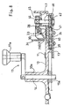
- Fig. 1 is an overall perspective view showing a token counting and sorting apparatus.
- Fig. 2 is perspective view showing the rear portion of the token counting and sorting apparatus.
- Fig. 3 is a plan view of the upper casing.
- Fig. 4 is an enlarged sectional view taken on lines IV-IV in Fig. 3, which is partially cut away.
- Fig. 5 is a plan view of the lower casing.
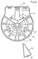
- Fig. 6 is a plan view showing the upper partition plate and a storage box.
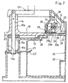
- Fig. 7 is an enlarged sectional view taken on lines VII-VII in Fig. 1, which is partially cut away.
- Fig. 8 is an enlarged sectional view taken on lines VIII-VIII in Fig. 5, which is partially cut away.
- Fig. 9 is a sectional view showing the transfer belt.
- Fig. 10(a) is a plan view showing a part of the rotary ring, Fig. 10(b) is an enlarged sectional view taken on lines Xb-Xb in Fig. 10(a), and Fig. 10(c) is an enlarged sectional view taken on lines Xc-Xc in Fig. 10(a).
- Fig. 11 is a plan view showing the token transfer inlet and the token discerner.
- Fig. 12 is an enlarged sectional view taken on lines XII-XII in Fig. 11.
- Fig. 13 is a sectional view taken on lines XII-XII in Fig. 12.
- Fig. 14 is an enlarged plan view showing detection holes.
- Fig. 15 is a block diagram of the controller.
-
- The present invention may be embodied in a variety of modified and alternative versions, though the drawings show particular (or optimum) examples of embodiments, which will be described below with reference to the drawings.
- However, the present invention is not to be limited to these particular embodiments but should be regarded as including all modified and alternative modes contained within the spirit and scope of the present invention defined in the claims.
- Fig. 1 is a perspective view showing a token counting and sorting apparatus. Fig. 2 is a perspective view showing a part of the apparatus as viewed from the rear side. Fig. 3 is a plan view of an upper casing. Fig. 4 is an enlarged sectional view of the upper casing, which is partially cut away. Fig. 5 is a plan view of a lower casing. Fig. 7 is an enlarged sectional view taken on lines VII-VII in Fig. 1.
- As shown in Figs. 1 through 7, the token counting and sorting
apparatus 1 according to the present invention comprises alower casing 2 and anupper casing 3 which are made of a synthetic resin and connected to each other by hinges 4 at their rear end portions for opening and closing movement. Theupper casing 3 may be releasably attached to thelower casing 2. - As shown in Fig. 2, the
lower casing 2 has a rear surface which is provided with alid 5 for opening and closing a battery box for accommodating a portable battery such as a dry battery. The rear surface is further provided with aconnector 6 for connection to an output of an AC adapter for converting commercial AC current to predetermined direct current. Theupper casing 3 has an upper surface which is provided, at the rear portion thereof, with adisplay 7 for displaying, for example, the number and sum oftokens 11 for each kind as well as the total number and sum of alltokens 11 detected by token discerner, which will be described later. The upper surface of the upper casing is also provided withdisplay switches 8 and apower switch 9 for example. Theupper casing 3 is generally centrally formed with a token feed opening 12 which is generally equal in diameter to arotary disc 10 and extends vertically through the upper casing for feeding thetokens 11 to the upper surface of therotary disc 10, which will be described later. - In this embodiment, the
tokens 11 to be counted and sorted may be EURO coins (unit: EURO) under European Monetary System including eight denominations, i.e. 0.01 EURO (diameter: 16.25mm), 0.02 EURO (diameter: 18.75mm), 0.05 EURO (diameter: 21.25mm), 0.10 EURO (diameter: 19.75mm), 0.20 EURO (diameter: 22.25mm), 0.50 EURO (diameter: 24.25mm), 1 EURO (diameter: 23.25mm), and 2 EURO (25.75mm). The tokens may be coins of the Japanese currency including six denominations i.e. 1-yen, 50-yen, 5-yen, 100-yen, 10-yen, and 500-yen in the order of increasing diameters. Thetokens 11 may be circular metal pieces for use with game machines. - The token counting and sorting
apparatus 1 according to the present invention includes therotary disc 10 which has an upper surface for supporting thetokens 11 of different kinds or denominations (having different diameters) and which is rotatable manually or by a driver. The apparatus further includes a generally arcuatetoken transfer track 23 extending along the outer circumference of therotary disc 10 and including atoken transfer inlet 24 for receiving tokens across the outer circumference of therotary disc 10. Thetoken transfer track 23 is formed with a plurality of sortingholes 25 for successively sorting and droppingtokens 11 in the order of increasing diameters as thetokens 11 are transferred from the upstream side toward the downstream side in the transfer direction. Disposed above the outer circumference of therotary disc 10 is atransfer belt 30 which rotates together with the rotary disc to transfer thetokens 11 while pressing the tokens against thetoken transfer track 23. In thetoken transfer track 23, atoken discerner 31 for counting the tokens while determining diameters of the tokens is provided between thetoken transfer inlet 24 and the sortinghole 25 which is located at the most upstream position in the transfer direction. The apparatus further includes a controller 32 for calculating results obtained by thetoken discerner 31. - The results calculated by the controller 32, i.e. the count of tokens for each kind (denomination) and a total number of the tokens for example are displayed at the
display 7. - The
rotary disc 10 in this embodiment is driven manually and the obverse (upper) surface thereof is centrally formed with an upwardly projectingboss 10a to which anupright shaft 14 is fitted. Theshaft 14 has a lower portion rotatably supported bybearings central cylinder 13a of anupper partition plate 13 defining the upper surface of thelower casing 2. The lower surface of therotary disc 10 is supported, at the outer circumferential portion thereof, by a plurality ofsupport rollers 16 provided at a stepped portion of theupper partition plate 13 for horizontal rotation of the disc. Theshaft 14 has an upper end to which ahandle 17 is pivotally connected via a pin. Thehandle 17 has agrip 17a which can be oriented to project upward (as shown in Figs. 1 and 8) for manual rotation by the operator. Thegrip 17a can be folded downward for decreasing the overall height of the apparatus when the apparatus is not used. - The
upper partition plate 13 of thelower casing 2 is formed with large through-holes 18 (eight holes in this embodiment) which are generally rectangular and circumferentially arranged as spaced from each other. Astorage box 19 which is formed of a synthetic resin for example and is generally triangular as viewed in plan is removably attached to thelower casing 2 below each of the through-holes 18 for collecting and storing tokens dropped through the through-hole. Thestorage box 19 is formed, at the outer circumferential surface thereof, with anengagement recess 20 for engagement with an operator's finger. Further, thestorage box 19 is formed, at the radially inner side thereof, with anengagement hole 21 for engagement with a corresponding one of engagement hooks 22 projecting radially outward from thecentral cylinder 13a of thelower casing 2 or theupper partition plate 13. Thus, thestorage box 19 is prevented from unintentionally detached to project outward of thelower casing 2. - The
upper partition plate 13 is upwardly provided with the generally arcuatetoken transfer track 23 arranged along the outer circumference of therotary disc 10 and including the transfer inlet 24 (See Fig. 5) for receiving tokens across the outer circumference of therotary disc 10, as well as the plurality of sortingholes 25 for successively sorting and droppingtokens 11 in the order of increasing diameters as thetokens 11 are transferred from the upstream side toward the downstream side in the transfer direction. (In this embodiment, eight sorting holes for sorting EURO coins of eight denominations are exemplarily illustrated.) - In this embodiment, the sorting holes 25, which are generally rectangular as viewed in plan, are formed in an abrasion-
resistant plate 26 made of e.g. an abrasion-resistant metal and constituting the bottom of thetoken transfer track 23. Theupper partition plate 13 is formed with a generally arcuate upwardly projectingrib 27 constituting the outer circumferential wall of thetoken transfer track 23. The inner circumferential wall of thetoken transfer track 23 is defined by anouter edge 29a of areference guide plate 29 which is generally arcuate and attached to the upper surface of the abrasion-resistant plate 26 outwardly of the outer circumference of therotary disc 10 by crimping or screwing. - The
reference guide plate 29 has a thickness which is slightly smaller than the minimum thickness of thetokens 11 to be sorted and specifically 1mm in this embodiment. Theouter edge 29a of the reference guide plate 29 (which corresponds to the inner circumferential wall of the token transfer track 23) is close to the outer circumference of therotary disc 10 at a portion adjacent thetoken transfer inlet 24 and gradually deviates away (farther) from the outer circumference of therotary disc 10 as it extends downstream in the transfer direction. - Each of the sorting holes 25 has an
inner side 25a and anouter side 25b which extend in parallel with theouter edge 29a of thereference guide plate 29. The distance between theouter edge 29a of thereference guide plate 29 and theouter side 25b of each sortinghole 25 is roughly equal to the diameter of the token 11 to be sorted at that hole. [Note that this does not hold for the last sorting hole (located at the most downstream position).] Further, the distance between theouter edge 29a of thereference guide plate 29 and theinner side 25a is about 1mm for supporting and transferring the token 11 with its circumferential edge held in slidable contact with theouter edge 29a. The distance between theouter edge 29a of thereference guide plate 29 and theouter side 25b of eachsubsequent sorting hole 25 progressively increases. For example, the distance between theouter edge 29a of thereference guide plate 29 and theouter side 25b of the sortinghole 25 located at the most upstream position is slightly larger than the diameter of 0.01 EURO coins having the smallest diameter but slightly smaller than the diameters of other larger EURO coins. Thus, among the coins (tokens 11) being transferred while sliding along theouter edge 29a of thereference guide plate 29, only 0.01 EURO coins drop into the sortinghole 25 located at the most upstream position while other larger coins (tokens 11) pass over that sortinghole 25. - In this way, the eight denominations of EURO coins, i.e. 0.01 EURO coins, 0.02 EURO coins, 0.10 EURO coins, 0.05 EURO coins, 0.20 EURO coins, 1 EURO coins, 0.50 EURO coins, 2 EURO coins successively drop into respective sorting holes 25 arranged from the upstream side toward downstream side in the transfer direction. Thus, the tokens can be sorted so that each
storage box 19 arranged at a respective sorting location can collect a single kind of tokens. -
Tokens 11 having the largest diameter drop through the sortinghole 25 of the last position (located at the most downstream position) for storage in therelevant storage box 19 so that thetokens 11 can be prevented from being transferred beyond the sortinghole 25 of the last position (located at the most downstream position). - The ring-shaped (annular)
transfer belt 30 is rotatably arranged on the lower side of theupper casing 3 and above the outer circumference of therotary disc 10. Thetransfer belt 30 rotates together with therotary disc 10 to transfer thetokens 11 downstream in the transfer direction while pressing, at the lower surface thereof, thetokens 11 against the upper surface of the abrasion-resistant plate 26 serving as thetoken transfer track 23. Specifically, as shown in Figs. 3 through 5, arotary ring 33 made of a synthetic resin is radially inwardly provided with a plurality of horizontal bearings 36 (six bearings in this embodiment). Thehorizontal bearings 36 slidably contact a ring-shapedrail 35 as a groove formed at the outer surface of atube 34 made of a synthetic resin and constituting a lower part of the token feed opening 12 of the upper casing, thereby supporting therotary ring 33 rotatably while also preventing unexpected detachment thereof. - The ring-shaped transfer belt 30 (endless belt) is upwardly formed with a ring-shaped
fitting groove 30a into which a ring-shapedengagement projection 33a formed at the lower surface of therotary ring 33 is elastically fitted so as not to be unexpectedly detached (See Figs.4 and 10(b)). Further, thetransfer belt 30 is formed, at the lower surface thereof, with a multiplicity ofelastic fins 37 projecting downward and circumferentially spaced from each other at a predetermined pitch. As shown in Fig. 9, each of thefins 37 is inclined toward the upstream side in the token transfer direction as the fin extends downward. Fig. 9 illustrates thetransfer belt 30 rotating clockwise. The left half of Fig. 9 illustrates thetransfer belt 30 as viewed from the outer circumferential side, whereas the right half of Fig. 9 illustrates thetransfer belt 30 as viewed from the inner circumferential side. - When there are no
tokens 11 on the token transfer track 23 (abrasion-resistant plate 26), the lower end of eachfin 37 does not slidably contact the abrasion-resistant plate 26 nor thereference guide plate 29 though held extremely close to the abrasion-resistant plate 26. On the other hand, when there existtokens 11 on the token transfer track 23 (abrasion-resistant plate 26), the lower end of thefin 37 elastically deforms to move thetokens 11 downstream in the transfer direction while pressing the tokens against the abrasion-resistant plate 26. - The radially inward lower corner of each
fin 37 of thetransfer belt 30 is rounded or in the form of acutting 37a for smoothly introducingtokens 11, which are released from therotary disc 10 to thetoken transfer inlet 24, to between the. fin and the abrasion-resistant plate 26. - A first
intermediate gear 40 for meshing withgear teeth 39 of the outer circumference of therotary disc 10, and a secondintermediate gear 41 for meshing with the first intermediate gear are supported by theupper partition plate 13 to be rotatable about respective shafts. A thirdintermediate gear 42 for meshing with the secondintermediate gear 41 has ashaft 46 which projects upward through acover 43 covering the upper surface of theupper partition plate 13. Theshaft 46 is provided, at the portion above the cover 32, with atransmission gear 45 attached thereto via a oneway clutch 44. Thetransmission gear 45 meshes withgear teeth 38 formed at the outer circumference of therotary ring 33. Thus, therotary disc 10 is driven for rotation together with therotary ring 33, i.e., thetransfer belt 30. The above-described parts starting from thegear 40 to thetransmission gear 45 constitute a driving mechanism. Theteeth 38 provided at the outer circumference of therotary ring 33 constitute a power transmission unit. - Referring to Fig. 5, when the
handle 17 is rotated clockwise to rotate therotary disc 10 in the arrow A direction (clockwise), thetransfer belt 30 rotates in the same direction. At this time, the circumferential speed of thetransfer belt 30 is preferably equal to or slightly lower than that of the outer circumference of therotary disc 10. When the circumferential speed of thetransfer belt 30 is excessively high, a great centrifugal force is exerted on thetokens 11 carried by thetransfer belt 30. As a result, thetokens 11 to be transferred are likely to deviate away from theouter edge 29a of thereference guide plate 29, which may increase sorting errors. - When the
tokens 11 jam at a portion adjacent thetoken transfer inlet 24 for example, thehandle 17 is rotated counterclockwise. At this time, thetransfer belt 30 is kept stationary due to the operation of the oneway clutch 44. - As shown in Fig. 5, the
outer edge 29a of thereference guide plate 29, which constitutes the inner circumferential wall of thetoken transfer track 23, is close to the outer circumference of therotary disc 10 at a portion adjacent thetoken transfer inlet 24 and gradually deviates away from the outer circumference of therotary disc 10 as it extends toward the downstream side. Specifically, thereference guide plate 29 is configured to bulge as viewed in plan between thetoken transfer inlet 24 and thetoken discerner 31 so that theouter edge 29a comes close to the inner circumference of thetransfer belt 30. - On the other hand, the ring-shaped
transfer belt 30, which is disposed above thetoken transfer track 23, is close to the outercircumferential wall 47 of thetoken transfer track 23 at a portion adjacent thetoken transfer inlet 24 and comes close to theouter edge 29a of thereference guide plate 29 as it extends toward the downstream side in the transfer direction. - Therefore, referring to Fig. 5, when each of the
tokens 11 on therotary disc 10 rotating clockwise is released to thetoken transfer inlet 24 due to the centrifugal force, the token 11 is caught by the radially inward lower end of thefin 37 of thetransfer belt 30 rotating together with the rotary disc. As thetransfer belt 30 rotates, the token 11 is transferred by rotating together with thefin 37. At this time, thefin 37 presses the token 11 against the upper surface of the abrasion-resistant plate 26 (token transfer track 23) while elastically deforming so that the lower end of the fin is inclined by a larger amount toward the upstream side in the transfer direction. - Before each of the
tokens 11 transferred downstream reaches thetoken discerner 31, the outer edge of the token 11 is pressed against and slides along theouter edge 29a of thereference guide plate 29. Therefore, by setting detection positions as will be described later, the diameter of the token 11 can be accurately determined at thetoken discerner 31 by referring to the distance from theouter edge 29a. - Although the
transfer belt 30 and therotary disc 10 are concentrically arranged in the illustrated embodiment, thetransfer belt 30 may be arranged eccentrically relative to therotary disc 10. - The outer
circumferential wall 47 of thetoken transfer track 23 includes anintroduction guide wall 47a extending between thetransfer inlet 24 and the token discerner 31 (See Figs. 5 and 11). Preferably, the distance between theintroduction guide wall 47a and theouter edge 29a of thereference guide plate 29 gradually decreases toward thetoken discerner 31, and the distance is preferably equal to or slightly larger than the maximum diameter of thetokens 11 to be sorted. With this structure, even when the token 11 deviates radially outward of thetransfer belt 11, the token 11 is guided along theintroduction guide wall 47a to come close to theouter edge 29a of thereference guide plate 29. Therefore, erroneous determination of the diameter of the token 11 can be eliminated. - Although the
fin 37 is flat and extends radially of therotary ring 33 in the above-described embodiment, the fin may be a round bar or a square bar. Alternatively, a plurality of (two to four) ring-shaped fins each projecting downward and having a relatively small thickness in the radial direction may be arranged concentrically with the rotary disc. - The
rotary ring 33 is provided with a downwardly projecting auxiliaryelastic member 49 made of rubber for example for preventing stagnation of thetokens 11 at thetoken transfer inlet 24. In one embodiment, as shown in Figs. 10(a), 10(b), 10(c) and 11, the auxiliary elastic member is so arranged as to pass radially inward of thetransfer belt 30 but slightly radially outward of atip end 29b of thereference guide plate 29 adjacent thetoken transfer inlet 24. Specifically, therotary ring 33 is radially inwardly provided with a vertically penetrating fixinghole 50 into which the auxiliaryelastic member 49 in the form of a bar made of rubber is inserted from below. The fixinghole 50 is upwardly provided withengagement projections elastic member 49 from coming off. - The lower end surface of the auxiliary
elastic member 49 is held out of contact with the upper surface of thereference guide plate 29 having a thickness smaller than that of the tokens 11 (See Fig. 12). Further, the lower end surface of the auxiliaryelastic member 49 moving together with the rotation of therotary ring 33 comes into contact with the upper surface of the token 11 which has become radially unmovable neither outwardly nor inwardly as a result of hitting against thetip end 29b of thereference guide plate 29 and flicks the token 11 radially outwardly as much as possible. In this embodiment, two auxiliary resilient members are provided at opposite positions diametrically of the rotary ring 33 (generally 180° opposite positions). - The
token discerner 31 is disposed in thetoken transfer track 23 between thetoken transfer inlet 24 and the sortinghole 25 at the most upstream position (the sortinghole 25 for the smallest token 11). Thetoken discerner 31 includes amagnetic sensor 51 for detecting the number oftransit tokens 11, and aphoto sensor unit 52 provided withphoto transmission cables 53 made of optical fibers for detecting the diameter of each token 11. Themagnetic sensor 51 can detecttokens 11 made of metals such as copper, cupro-nickel, aluminum, nickel, steel for example. Themagnetic sensor 51 is fixedly attached from below to a fixinghole 54 formed in theupper partition plate 13 of the lower casing at a position close to theouter edge 29a of thereference guide plate 29 in facing relationship to ahole 55 formed in the abrasion-resistant plate 26 (See Fig. 12). - The
photo sensor unit 52 includes alight emitting portion 56 comprising light-emittingelements 58 such as light emitting diodes arranged below anelongated slot 57 extending in the abrasion-resistant plate 26 perpendicularly to the transfer direction of thetokens 11. The light-emitting elements are arranged generally in a row extending longitudinally of theslot 57 for emitting light upwardly. Thephoto sensor unit 52 further includes alight receiving portion 60 comprising a plurality (seven in this embodiment) of detection holes 61a-61g formed in asensor casing 59 fixedly disposed in facing relationship to theslot 57 via the abrasion-resistant plate 26, andlight receiving elements 62a-62g corresponding in number to the detection holes 61 and fixed to thesensor casing 59 as spaced from the detection holes 61, and the corresponding number ofphoto transmission cables 53 for connecting therebetween. Each of thephoto transmission cables 53 has one end (light input end) fixedly inserted into a corresponding one of the detection holes 61a-61g and the other end (light output end) fixedly inserted into a corresponding one ofholes 63 provided in facing relationship to thelight receiving elements 62a-62g. The upper side of thesensor casing 59 is covered with acover plate 64 so that unnecessary light from above (external portions) does not enter thephoto transmission cables 53 and theholes 63. - When a token 11 made of a metal passes the
magnetic sensor 51, a detection signal is outputted as a pulse (which is generally rectangular). Almost at the same time, a diameter-indicating signal is outputted as a pulse (which is also generally rectangular) as the token 11 having a predetermined diameter passes across thelight receiving elements 62a-62g. These signals are inputted via aninterface 67 to aCPU 66 as an electronic controlling unit 65 (See Fig. 15) such as a microcomputer. In theCPU 66, the count oftokens 11 for each kind and the total number of thetokens 11 are calculated. The results (the number and amount (sum) of thetokens 11 for each kind as well as the total number and amount (total sum) of the tokens) may be stored in a RAM (random-access memory) and can be numerically displayed on thedisplay 7 by operating the display switches 8. The ROM (read-only memory) is provided to store a control program such as the control algorithm. Thecontroller 65 may be accommodated at an appropriate position of thelower casing 2 or theupper casing 3. - As shown in Fig. 14, the detection holes 61a-61g are so arranged as to discern the tokens of progressively increasing diameters. That is, when a token 11 passing is sensed (detected) only by the
magnetic sensor 51, the token is determined to be 0.01 EURO coin which has the smallest diameter (=16.25mm). When a token 11 passing is detected by themagnetic sensor 51 as well as by the detection hole 61a, the token 11 is determined to be 0.02 EURO coin (diameter: 18.75mm). When a token 11 passing is detected by themagnetic sensor 51 as well as by thedetection holes 61a, 61b, the token 11 is determined to be 0.10 EURO coin (diameter: 19.75mm). Similarly, a token detected by themagnetic sensor 51 as well as thedetection holes 61a, 61b, 61c is determined to be 0.05 EURO coin (diameter: 21.25mm), a token detected by themagnetic sensor 51 as well as thedetection holes magnetic sensor 51 as well as thedetection holes magnetic sensor 51 as well as thedetection holes magnetic sensor 51 as well as thedetection holes - For the tokens like monetary coins where tokens differ diametrically from one another stepwise by about 1.0-1.5mm and where the manufacturing errors are very minor with respect to the diameter of each token, accurate stepwise discernment of tokens may be performed by employing detection holes 61 of a small diameter. Further, owing to the arrangement where the
light receiving elements 62 are arranged as spaced from the detection holes 61 and connected to the detection holes by thephoto transmission cables 53 for signal transmission, the necessity for using extremely small light receiving elements can be eliminated. (Although the transmission cable comprises oneoptical fiber having a diameter of 0.5mm in this embodiment, the transmission cable may comprise a bundle of fibers of a smaller diameter.) Thus, the apparatus of the present invention can be manufactured from conventional parts so that the manufacturing cost can be prevented from increasing. For thelight receiving element 62, use may be made of a photoconductive element, a photodiode, a phototransistor, a photo thyrister or the like. - Further, by incorporating the detection holes 61 and the
light receiving elements 62 in thesensor casing 59, the manufacturing accuracy as well as the detection accuracy of the apparatus can be enhanced while realizing reduction of the manufacturing cost. - In another embodiment, for the photo sensor (light receiving element) for determining the diameter of a token, use may be made of a line-type imaging device (CCD) or a photoelectric conversion element such as a solar battery.
- Instead of the
magnetic sensor 51, a light-reflective sensor may be used for determining the number of thetransit tokens 11. - The
lower casing 2 is provided with an upwardly projectinglock segment 71 for engagement and disengagement relative to anengagement hole 72 formed at the front end of theupper casing 3. Thus, the upper and thelower casings - Instead of manual rotation, the
rotary disc 10 may be rotated by a driving motor. - Further, instead of each of the
storage boxes 19, a hopper (not shown) may be releasably mounted to thelower casing 2 for communicating with a respective one of the sorting holes 25. A storage bag (not shown) for directly storing the sorted tokens may be releasably attached to the hopper.
Claims (9)
- An apparatus for counting and sorting different kinds of tokens comprising:a rotary disc having an upper surface for supporting the tokens, the disc being rotatable manually or by a driver;a generally arcuate token transfer track extending along an outer circumference of the rotary disc and including a token transfer inlet for receiving the tokens across the outer circumference of the rotary disc;a plurality of sorting holes formed in the token transfer track for successively sorting and dropping the tokens in an order of increasing diameters as the tokens are transferred from an upstream side toward an downstream side in a transfer direction;an annular transfer belt disposed above the outer circumference of the rotary disc for rotation together with the rotary disc to transfer the tokens while pressing the tokens against a surface of the token transfer track;a token discerner provided in the token transfer track between the token transfer inlet and the sorting hole located at the most upstream position in the transfer direction for counting the tokens while determining diameters of the tokens;a controller for calculating results obtained by the token discerner; anda display for displaying the calculated results which include the count of tokens for each kind and a total number of the tokens.
- The token counting and sorting apparatus according to claim 1, further comprising a reference guide plate providing an inner circumferential wall of the token transfer track and disposed outward of the outer circumference of the rotary disc, the reference guide plate being arranged so that the inner circumferential wall is close to the outer circumference of the rotary disc at a portion adjacent the token transfer inlet and gradually deviates away from the outer circumference of the rotary disc while approaching an inner circumference of the transfer belt between the token transfer inlet and the token discerner as the inner circumferential wall extends downstream in the transfer direction.
- The token counting and sorting apparatus according to claim 2, wherein the transfer belt is disposed above the token transfer track, the transfer belt being arranged to be close to an outer circumferential wall of the token transfer track at a portion adjacent the token transfer inlet and gradually approach the reference guide plate as the transfer belt extends downstream in the transfer direction.
- The token counting and sorting apparatus according to any one of claims 1 through 3, wherein the transfer belt has a lower surface formed with projecting fins which are elastically deformable for pressing the tokens toward an upper surface of the token transfer track.
- The token counting and sorting apparatus according to any one of claims 1 through 4, further comprising an auxiliary elastic member projecting downward between the outer circumference of the rotary disc and the inner circumference of the transfer belt for rotating together with the transfer belt for preventing stagnation of the tokens at a portion adjacent the token transfer inlet.
- The token counting and sorting apparatus according to any one of claims 1 through 5, wherein the rotary disc and the token transfer track are provided in a lower casing, the transfer belt being mounted to a rotary ring which is rotatably mounted to an upper casing capable of opening and closing movement relative to the lower casing, the upper casing being provided with a token feed opening radially inward from the rotary ring for feeding the tokens toward the rotary disc, the rotary ring being provided with a power transmission unit driven for rotation by a driving mechanism of the lower casing.
- The token counting and sorting apparatus according to any one of claims 1 through 6, wherein the lower surface of the transfer belt is formed with a multiplicity of projecting fins each of which is inclined toward the upstream side in the transfer direction as the fin extends downward.
- The token counting and sorting apparatus according to any one of claims 1 through 7, wherein the token discerner comprises detection holes respectively arranged at positions for determining the diameters of the tokens, and photo sensors disposed separately from the detection holes and connected thereto via photo transmission cables.
- The token counting and sorting apparatus according to any one of claims 1 through 8, further comprising a storage box or a hopper releasably mounted below each of the sorting holes for collecting and storing the tokens sorted, the hopper being provided with a storage bag removably attached thereto.
Applications Claiming Priority (3)
| Application Number | Priority Date | Filing Date | Title |
|---|---|---|---|
| JP23422999A JP3299730B2 (en) | 1999-08-20 | 1999-08-20 | Counting and sorting equipment for coins |
| JP23422999 | 1999-08-20 | ||
| PCT/JP2000/004398 WO2001015090A1 (en) | 1999-08-20 | 2000-06-30 | Coin counting and sorting device |
Publications (3)
| Publication Number | Publication Date |
|---|---|
| EP1223562A1 true EP1223562A1 (en) | 2002-07-17 |
| EP1223562A4 EP1223562A4 (en) | 2003-05-21 |
| EP1223562B1 EP1223562B1 (en) | 2004-08-18 |
Family
ID=16967729
Family Applications (1)
| Application Number | Title | Priority Date | Filing Date |
|---|---|---|---|
| EP00942446A Expired - Lifetime EP1223562B1 (en) | 1999-08-20 | 2000-06-30 | Coin counting and sorting device |
Country Status (6)
| Country | Link |
|---|---|
| US (1) | US6679770B1 (en) |
| EP (1) | EP1223562B1 (en) |
| JP (1) | JP3299730B2 (en) |
| DE (1) | DE60013157T2 (en) |
| ES (1) | ES2222214T3 (en) |
| WO (1) | WO2001015090A1 (en) |
Cited By (6)
| Publication number | Priority date | Publication date | Assignee | Title |
|---|---|---|---|---|
| WO2005055158A1 (en) * | 2003-12-02 | 2005-06-16 | Scan Coin Industries Ab | A coin handling apparatus having slidably displaceable housing parts |
| US7658668B2 (en) | 2005-09-17 | 2010-02-09 | Scan Coin Ab | Coin handling equipment |
| US20100097736A1 (en) * | 2006-12-14 | 2010-04-22 | Alexander Apostolov | Method and an apparatus for protecting a bus in a three-phase electrical power system |
| US8092284B2 (en) | 2005-07-17 | 2012-01-10 | Scan Coin Ab | Coin handling equipment |
| US8136723B2 (en) | 2006-02-10 | 2012-03-20 | Scan Coin Ab | Cash handling |
| CN111282162A (en) * | 2020-03-04 | 2020-06-16 | 西安交通大学医学院第二附属医院 | Adjustable support for radiotherapy |
Families Citing this family (16)
| Publication number | Priority date | Publication date | Assignee | Title |
|---|---|---|---|---|
| DE19622533A1 (en) * | 1996-06-05 | 1997-12-11 | Deutsche Telekom Ag | Method and device for loading input data into an algorithm during authentication |
| US20060154589A1 (en) * | 2005-01-11 | 2006-07-13 | String Gregory F | High speed coin processing machine |
| JP4849368B2 (en) * | 2006-01-23 | 2012-01-11 | 旭精工株式会社 | Coin dispenser |
| US8708129B2 (en) * | 2007-08-17 | 2014-04-29 | Talaris, Inc. | Method and system for dust prevention in a coin handling machine |
| US8475242B2 (en) * | 2010-08-13 | 2013-07-02 | Gregory F. String | Coin sorting plate with recessed coin slots |
| JP5513322B2 (en) * | 2010-08-31 | 2014-06-04 | 沖電気工業株式会社 | Coin processing equipment |
| JP5510240B2 (en) * | 2010-09-24 | 2014-06-04 | 沖電気工業株式会社 | Coin processing equipment |
| EP2784756B1 (en) | 2013-03-28 | 2020-03-18 | Scan Coin Ab | Rim geometry of a coin sorting device |
| EP2784757B1 (en) | 2013-03-28 | 2019-09-04 | Scan Coin Ab | A coin counting and sorting module |
| CN103366453B (en) * | 2013-08-05 | 2016-06-08 | 南京中钞长城金融设备有限公司 | A kind of identification coin disparting mechanism |
| US10685523B1 (en) * | 2014-07-09 | 2020-06-16 | Cummins-Allison Corp. | Systems, methods and devices for processing batches of coins utilizing coin imaging sensor assemblies |
| CN105160752B (en) * | 2015-09-18 | 2017-11-14 | 李永强 | A kind of coin sorter |
| CN105957227B (en) * | 2016-04-25 | 2018-08-03 | 武汉商学院 | Coin-sorting device |
| WO2018101173A1 (en) * | 2016-11-30 | 2018-06-07 | グローリー株式会社 | Coin delivery device |
| WO2019083065A1 (en) * | 2017-10-27 | 2019-05-02 | 은남표 | Coin counting apparatus |
| KR102203230B1 (en) | 2019-04-12 | 2021-01-13 | 은남표 | apparatus to count the coin |
Citations (4)
| Publication number | Priority date | Publication date | Assignee | Title |
|---|---|---|---|---|
| US4437478A (en) * | 1980-07-08 | 1984-03-20 | Asahi Seiko Kabushiki Kaisha | Coin counting and dispensing apparatus |
| US4586522A (en) * | 1984-04-03 | 1986-05-06 | Brandt, Inc. | Coin handling and sorting |
| WO1992022044A1 (en) * | 1991-06-03 | 1992-12-10 | Cummins-Allison Corp. | Disc-type coin sorter |
| US5295899A (en) * | 1992-03-03 | 1994-03-22 | Adams Thomas P | Two disc coin handling apparatus |
Family Cites Families (16)
| Publication number | Priority date | Publication date | Assignee | Title |
|---|---|---|---|---|
| US4598724A (en) * | 1984-08-22 | 1986-07-08 | Wellman Company, Inc. | Coin counter |
| JPH0831151B2 (en) | 1987-04-07 | 1996-03-27 | ロ−レルバンクマシン株式会社 | Coin sorter |
| JPS6446894A (en) | 1987-08-17 | 1989-02-21 | Ace Denken Kk | Coin feeder |
| JPH0321170A (en) | 1989-03-31 | 1991-01-29 | Sanyo Electric Co Ltd | Synchronizing signal separator circuit |
| JPH0317866A (en) | 1989-06-15 | 1991-01-25 | Sony Corp | Data reader |
| JPH082760Y2 (en) * | 1989-07-03 | 1996-01-29 | 株式会社サンテックス | Power transmission structure of coin processing machine |
| JPH082761Y2 (en) * | 1989-07-06 | 1996-01-29 | 日本金銭機械株式会社 | Coin sorter |
| TW208747B (en) | 1991-10-03 | 1993-07-01 | Roreru Bank Machine Kk | |
| JP2634123B2 (en) | 1992-04-22 | 1997-07-23 | ローレルバンクマシン株式会社 | Coin sorting and sorting machine |
| US5401211A (en) | 1993-08-05 | 1995-03-28 | Cummins-Allison Corp. | Disc coin sorter with positive guide wall between exit channels |
| US5514034A (en) * | 1993-09-28 | 1996-05-07 | Cummins-Allison Corp. | Apparatus and method for terminating coin sorting using pressureless exit channels and immediate stopping |
| US5607351A (en) | 1994-11-10 | 1997-03-04 | Automated Currency Instruments, Inc. | Coin counting machine |
| SE504813C2 (en) | 1995-08-21 | 1997-04-28 | Scan Coin Ab | Machine for counting and sorting coins |
| AU1696697A (en) | 1996-01-11 | 1997-08-01 | Brandt Inc. | Coin sorter with coin recognition |
| US5688166A (en) * | 1996-07-10 | 1997-11-18 | Chen; Chih-Nan | Apparatus for counting coins |
| JP2926047B1 (en) * | 1998-06-15 | 1999-07-28 | 有限会社スガイ総業 | Coin counting device |
-
1999
- 1999-08-20 JP JP23422999A patent/JP3299730B2/en not_active Expired - Lifetime
-
2000
- 2000-06-30 DE DE60013157T patent/DE60013157T2/en not_active Expired - Fee Related
- 2000-06-30 EP EP00942446A patent/EP1223562B1/en not_active Expired - Lifetime
- 2000-06-30 US US10/069,060 patent/US6679770B1/en not_active Expired - Fee Related
- 2000-06-30 ES ES00942446T patent/ES2222214T3/en not_active Expired - Lifetime
- 2000-06-30 WO PCT/JP2000/004398 patent/WO2001015090A1/en active IP Right Grant
Patent Citations (4)
| Publication number | Priority date | Publication date | Assignee | Title |
|---|---|---|---|---|
| US4437478A (en) * | 1980-07-08 | 1984-03-20 | Asahi Seiko Kabushiki Kaisha | Coin counting and dispensing apparatus |
| US4586522A (en) * | 1984-04-03 | 1986-05-06 | Brandt, Inc. | Coin handling and sorting |
| WO1992022044A1 (en) * | 1991-06-03 | 1992-12-10 | Cummins-Allison Corp. | Disc-type coin sorter |
| US5295899A (en) * | 1992-03-03 | 1994-03-22 | Adams Thomas P | Two disc coin handling apparatus |
Non-Patent Citations (1)
| Title |
|---|
| See also references of WO0115090A1 * |
Cited By (6)
| Publication number | Priority date | Publication date | Assignee | Title |
|---|---|---|---|---|
| WO2005055158A1 (en) * | 2003-12-02 | 2005-06-16 | Scan Coin Industries Ab | A coin handling apparatus having slidably displaceable housing parts |
| US8092284B2 (en) | 2005-07-17 | 2012-01-10 | Scan Coin Ab | Coin handling equipment |
| US7658668B2 (en) | 2005-09-17 | 2010-02-09 | Scan Coin Ab | Coin handling equipment |
| US8136723B2 (en) | 2006-02-10 | 2012-03-20 | Scan Coin Ab | Cash handling |
| US20100097736A1 (en) * | 2006-12-14 | 2010-04-22 | Alexander Apostolov | Method and an apparatus for protecting a bus in a three-phase electrical power system |
| CN111282162A (en) * | 2020-03-04 | 2020-06-16 | 西安交通大学医学院第二附属医院 | Adjustable support for radiotherapy |
Also Published As
| Publication number | Publication date |
|---|---|
| JP2001060277A (en) | 2001-03-06 |
| JP3299730B2 (en) | 2002-07-08 |
| WO2001015090A1 (en) | 2001-03-01 |
| DE60013157T2 (en) | 2004-12-30 |
| EP1223562A4 (en) | 2003-05-21 |
| ES2222214T3 (en) | 2005-02-01 |
| DE60013157D1 (en) | 2004-09-23 |
| EP1223562B1 (en) | 2004-08-18 |
| US6679770B1 (en) | 2004-01-20 |
Similar Documents
| Publication | Publication Date | Title |
|---|---|---|
| EP1223562B1 (en) | Coin counting and sorting device | |
| US6772870B2 (en) | Token counting and sorting apparatus | |
| US5230653A (en) | Currency sorting apparatus | |
| AU754889B2 (en) | Coin distributor | |
| EP0137265A2 (en) | Coin-queueing head for high-speed coin-sorting and counting apparatus | |
| US20090008215A1 (en) | "money item dispensing apparatus" | |
| US7244175B2 (en) | Coin recycling machine and method | |
| US20090048803A1 (en) | Method and sensor for sensing coins for valuation | |
| WO2018101414A1 (en) | Coin processing device | |
| CA2435768C (en) | Electronically-controlled rotary coin change dispenser | |
| EP2325810B1 (en) | Coin feeder and coin processing machine | |
| EP1037174B1 (en) | Device for counting coins or the like | |
| US7472780B2 (en) | Coin sorting apparatus, control system for controlling coin sorting apparatus, and method for sorting coins | |
| EP3220363A1 (en) | Coin handling apparatus | |
| JP3950949B2 (en) | Coin denomination sorter | |
| JP5561479B2 (en) | Coin sorting and counting device | |
| KR100424984B1 (en) | Coin counting and sorting device | |
| JP5021703B2 (en) | Coin deposit / withdrawal device | |
| KR100636644B1 (en) | Digital auto cash counter | |
| KR20050075479A (en) | Coin sort counting machine | |
| JPH02148381A (en) | Money discriminating machine | |
| JP2002277214A (en) | Dimension discriminating device and method therefor | |
| JP2000067295A (en) | Coin processor |
Legal Events
| Date | Code | Title | Description |
|---|---|---|---|
| PUAI | Public reference made under article 153(3) epc to a published international application that has entered the european phase |
Free format text: ORIGINAL CODE: 0009012 |
|
| 17P | Request for examination filed |
Effective date: 20020319 |
|
| AK | Designated contracting states |
Kind code of ref document: A1 Designated state(s): AT BE CH CY DE DK ES FI FR GB GR IE IT LI LU MC NL PT SE |
|
| A4 | Supplementary search report drawn up and despatched |
Effective date: 20030408 |
|
| EL | Fr: translation of claims filed | ||
| GRAP | Despatch of communication of intention to grant a patent |
Free format text: ORIGINAL CODE: EPIDOSNIGR1 |
|
| GRAS | Grant fee paid |
Free format text: ORIGINAL CODE: EPIDOSNIGR3 |
|
| GRAL | Information related to payment of fee for publishing/printing deleted |
Free format text: ORIGINAL CODE: EPIDOSDIGR3 |
|
| GRAS | Grant fee paid |
Free format text: ORIGINAL CODE: EPIDOSNIGR3 |
|
| GRAA | (expected) grant |
Free format text: ORIGINAL CODE: 0009210 |
|
| AK | Designated contracting states |
Kind code of ref document: B1 Designated state(s): DE ES FR GB IT |
|
| REG | Reference to a national code |
Ref country code: GB Ref legal event code: FG4D |
|
| REG | Reference to a national code |
Ref country code: IE Ref legal event code: FG4D |
|
| REF | Corresponds to: |
Ref document number: 60013157 Country of ref document: DE Date of ref document: 20040923 Kind code of ref document: P |
|
| REG | Reference to a national code |
Ref country code: ES Ref legal event code: FG2A Ref document number: 2222214 Country of ref document: ES Kind code of ref document: T3 |
|
| ET | Fr: translation filed | ||
| PLBE | No opposition filed within time limit |
Free format text: ORIGINAL CODE: 0009261 |
|
| STAA | Information on the status of an ep patent application or granted ep patent |
Free format text: STATUS: NO OPPOSITION FILED WITHIN TIME LIMIT |
|
| 26N | No opposition filed |
Effective date: 20050519 |
|
| PGFP | Annual fee paid to national office [announced via postgrant information from national office to epo] |
Ref country code: ES Payment date: 20090623 Year of fee payment: 10 |
|
| PGFP | Annual fee paid to national office [announced via postgrant information from national office to epo] |
Ref country code: FR Payment date: 20090615 Year of fee payment: 10 Ref country code: IT Payment date: 20090624 Year of fee payment: 10 |
|
| PGFP | Annual fee paid to national office [announced via postgrant information from national office to epo] |
Ref country code: DE Payment date: 20090622 Year of fee payment: 10 Ref country code: GB Payment date: 20090618 Year of fee payment: 10 |
|
| GBPC | Gb: european patent ceased through non-payment of renewal fee |
Effective date: 20100630 |
|
| REG | Reference to a national code |
Ref country code: FR Ref legal event code: ST Effective date: 20110228 |
|
| PG25 | Lapsed in a contracting state [announced via postgrant information from national office to epo] |
Ref country code: IT Free format text: LAPSE BECAUSE OF NON-PAYMENT OF DUE FEES Effective date: 20100630 |
|
| PG25 | Lapsed in a contracting state [announced via postgrant information from national office to epo] |
Ref country code: DE Free format text: LAPSE BECAUSE OF NON-PAYMENT OF DUE FEES Effective date: 20110101 |
|
| PG25 | Lapsed in a contracting state [announced via postgrant information from national office to epo] |
Ref country code: FR Free format text: LAPSE BECAUSE OF NON-PAYMENT OF DUE FEES Effective date: 20100630 |
|
| REG | Reference to a national code |
Ref country code: ES Ref legal event code: FD2A Effective date: 20110714 |
|
| PG25 | Lapsed in a contracting state [announced via postgrant information from national office to epo] |
Ref country code: ES Free format text: LAPSE BECAUSE OF NON-PAYMENT OF DUE FEES Effective date: 20110704 Ref country code: GB Free format text: LAPSE BECAUSE OF NON-PAYMENT OF DUE FEES Effective date: 20100630 |
|
| PG25 | Lapsed in a contracting state [announced via postgrant information from national office to epo] |
Ref country code: ES Free format text: LAPSE BECAUSE OF NON-PAYMENT OF DUE FEES Effective date: 20100701 |