EP1208882A2 - Arrangement for supporting a wheel of a roller skate - Google Patents
Arrangement for supporting a wheel of a roller skate Download PDFInfo
- Publication number
- EP1208882A2 EP1208882A2 EP01127572A EP01127572A EP1208882A2 EP 1208882 A2 EP1208882 A2 EP 1208882A2 EP 01127572 A EP01127572 A EP 01127572A EP 01127572 A EP01127572 A EP 01127572A EP 1208882 A2 EP1208882 A2 EP 1208882A2
- Authority
- EP
- European Patent Office
- Prior art keywords
- bracket
- frame
- wheel
- roller skate
- hole
- Prior art date
- Legal status (The legal status is an assumption and is not a legal conclusion. Google has not performed a legal analysis and makes no representation as to the accuracy of the status listed.)
- Withdrawn
Links
Images


Classifications
-
- A—HUMAN NECESSITIES
- A63—SPORTS; GAMES; AMUSEMENTS
- A63C—SKATES; SKIS; ROLLER SKATES; DESIGN OR LAYOUT OF COURTS, RINKS OR THE LIKE
- A63C17/00—Roller skates; Skate-boards
-
- A—HUMAN NECESSITIES
- A63—SPORTS; GAMES; AMUSEMENTS
- A63C—SKATES; SKIS; ROLLER SKATES; DESIGN OR LAYOUT OF COURTS, RINKS OR THE LIKE
- A63C17/00—Roller skates; Skate-boards
- A63C17/008—Roller skates; Skate-boards with retractable wheel, i.e. movable relative to the chassis out of contact from surface
-
- A—HUMAN NECESSITIES
- A63—SPORTS; GAMES; AMUSEMENTS
- A63C—SKATES; SKIS; ROLLER SKATES; DESIGN OR LAYOUT OF COURTS, RINKS OR THE LIKE
- A63C17/00—Roller skates; Skate-boards
- A63C17/20—Roller skates; Skate-boards with fixable wheels permitting the skates to be used for walking
Definitions
- the present invention relates to an improvement of a structure for supporting a wheel of a roller skate, and, more particularly, to a structure for supporting a wheel of a roller skate which enables a wheel coupled to an outsole of a roller skate to be supported and retracted simply and reliably, thereby improving reliability of operation of a roller support structure.
- a frame 60 consisting of a pair of box containers having a predetermined width and connecting walls fixedly disposed between the two box containers, all of which are integrally formed, is attached to an outsole 20.
- Each of the box containers is provided at its both side plates with curved and elongated slide holes 61 and locking holes 62 such that the slide holes 61 and the locking holes 62 formed at the both side plates of the box container are aligned with each other.
- a bracket 30 adapted to rotatably support a wheel 50 can be received in the receiving room of the box container.
- a rectangular base plate 70 is rotatably coupled to an upper surface of the bracket 30 by means of a coupling pin 40.
- the base plate 70 is provided at a side, i.e. at a front side or rear side, with a pair of swing pins 71 facing each other, and at the other side with a pair of locking protrusions 72 to be biased outwardly. Therefore, the swing pins 71 are fitted in the slide holes 61 so that they can be moved up and down within a predetermined range corresponding to the length of the slide holes 61.
- the biased locking protrusions 72 are releasably fitted in the locking holes 62 of the frame 60.
- Such a conventional structure for supporting a wheel of a roller skate is designed to allow the base plate 70 to swing about the swing pins 71.
- the bracket 30 and the wheel 50 are first drawn from the receiving room of the box container.
- a lower surface of the base plate 70 is registered with a virtual plane defined by bottom edges of the frame 60 so that the bracket 30 coupled to the lower surface of the base plate 70 can be rotated about the coupling pin 40.
- the locking protrusions 72 are slightly moved upward such that the locking protrusions 72 are fitted into the locking holes 62.
- both the locking protrusions 72 are first compressed inwardly and then slightly drawn downward. Subsequently, the bracket 30 is rotated 90° and again pushed upward. Consequently, the bracket 30 and the base plate 70 are turned about the slide pins 71 to be receiving into the received room.
- the bracket 30 is provided at its lower surface with a locking pin 33 which is biased outward by a spring, and the box container of the frame 60 is formed with a second locking hole 63 corresponding to the locking pin 33. Therefore, when the bracket 30 and the wheel 50 are received in the receiving room, the second locking pin 33 is fitted into the corresponding locking hole 63 of the frame 60, thereby causing the bracket 30 to be stably maintained therein.
- the above-mentioned conventional structure for supporting a wheel has disadvantages in that the supporting structure is somewhat coarse and complicated because the base plate 70 is supported by the rocking protrusions 72 and the swing pins 71 and the bracket 30 is supported by the second locking pin 33; and the wheel 50 rattles because the swing pins 71 can be moved along the slide elongated holes 61, thereby causing unpleasant noise that may adversely affecting reliability of products.
- an object of the present invention is to provide a structure for supporting a wheel of a roller skate which enables a wheel coupled to an outsole of a roller skate to be supported and retracted simply and reliably.
- the present invention provides a structure for supporting a wheel of a roller skate which includes a box-shaped frame attached to an outsole of the roller skate, which has at its bottom wall fitting recesses and at its side wall a passage opening; a swing plate pivotally connected to the frame; and a bracket rotatably coupled to the swing plate, which can be elastically spaced from the swing plate by elastic means and has a fitting protrusion to be fitted in the recesses of the frame, whereby the bracket can be pulled out of the fitting recesses and rotated 90° followed by being pushed into the frame through the passage opening.
- Figs. 4 to 6 show structures for supporting wheels of a roller skate according to the present invention.
- an outsole 2 of a roller skate to which a structure according to the present invention is attached is formed with rectangular receiving rooms 2a at appropriate positions.
- Each of the receiving rooms 2a receives a base frame 1 therein.
- the base frame 1 is shaped into a box shape with an upper side and a front or a rear side opened, and provided at its both upper ends with flanges 1a each having a screw hole.
- the frame 1 can be fixedly attached to the outsole 2 of the roller skate by tightening screws into the outsole 2 through the screw holes.
- the frame 1 is formed at its bottom surface with a pair of protrusions 1b which are slightly extended inwardly to face each other.
- the bottom surface of the frame 1 is formed at its both sides with fitting recesses 1c. Therefore, the bottom surface of the frame 1 has a "T"-shaped cut portion.
- a pair of vertical walls are provided at its front or rear side with hinge pins 4a, respectively, and a swing plate 4 is pivotally coupled to the frame 1 via the hinge pins 4a.
- a bracket 5 is rotatably coupled to the swing plate 4.
- the bracket 5 has a pair of arms extended downward, between which a wheel 6 is rotatably supported.
- the bracket 5 has at its top surface a crosswise protrusion 5a which is adapted to be releasably fitted in the fitting recesses 1c of the frame 1.
- the bracket 5 is formed at its top wall with a counterbored through hole 5b.
- a bolt stud 8 is threaded into the counterbored through hole 5b through a coil spring 7 interposed therebetween so that the coil spring 7 is disposed between a bolt head seat of the counterbored hole 5b and a head of the bolt stud 8.
- the swing plate 4 is centrally formed with a threaded hole 4b such that a lower end of the bolt stud 8 can be releasably threaded into the threaded hole 4b.
- the top protrusion 5a of the bracket 5 is fitted into the fitting recesses 1c formed at the lower end of the frame 1, and shoulders disposed at both sides of the top protrusion 5a are engaged with the protrusions 1b and the bottom surface of the frame 1, thereby preventing the bracket 5 from being moved back and forth.
- the bracket 5 since the bracket 5 is upward biased by the coil spring 7 interposed between the bracket 5 and the bolt stud 8, the bracket 5 can be more securely attached to the frame 1.
- the top protrusion 5a of the bracket 5 is taken out of the fitting recesses 1c of the frame 1 while compressing the coil spring 7, thereby allowing the bracket 5 to be rotated about the bolt stud 8.
- the bracket 5 is rotated 90° in a state of being out of the fitting recesses 1c, the top protrusion 5a of the bracket 5 comes into contact with the swing plate 4 at its side. Thereafter, as the swing plate 4 is turned upward about the hinge pin 4a, the bracket 5 and the wheel 6 which are coupled to the swing plate 4 are received in the receiving room 2a of the outsole 2.
- the bracket 5 is closely fitted between the facing protrusions 1b of the frame 1, thereby causing the wheel 6 to be maintained in the receiving room 2a.
- the coil spring 7 is designed to have an elasticity sufficient to cause the swing plate 4 and the bracket 5 to be strongly coupled to each other.
- the protrusions 1b formed at the bottom end of the frame 1 are extended inwardly such that the protrusions 1b have a predetermined spacing therebetween to allow the rotated bracket 5 to be passed therethrough.
- the present invention provides a structure for supporting a wheel of a roller skate which enables a bracket and a wheel to be retracted into a receiving room of an outsole of the roller skate easily and reliably by a simple operation of pulling and turning the bracket or the wheel 90° and then pushing it into the receiving room of the outsole. By carrying out the operation in reverse, the wheel can be extended from the receiving room without difficulty. Furthermore, since the bracket is subjected to elasticity of a coil spring, the top portion of the bracket can be coupled to a frame more stably and securely.
Abstract
Description
- The present invention relates to an improvement of a structure for supporting a wheel of a roller skate, and, more particularly, to a structure for supporting a wheel of a roller skate which enables a wheel coupled to an outsole of a roller skate to be supported and retracted simply and reliably, thereby improving reliability of operation of a roller support structure.
- Referring to Figs 1 to 3, there are shown a second embodiment of a roller skate disclosed the Korean Utility Model No. 2000-29812 filed by the applicant. As shown in the drawings, a
frame 60 consisting of a pair of box containers having a predetermined width and connecting walls fixedly disposed between the two box containers, all of which are integrally formed, is attached to anoutsole 20. Each of the box containers is provided at its both side plates with curved andelongated slide holes 61 and lockingholes 62 such that theslide holes 61 and thelocking holes 62 formed at the both side plates of the box container are aligned with each other. With theslide holes 61 and thelocking holes 62, abracket 30 adapted to rotatably support awheel 50 can be received in the receiving room of the box container. - A
rectangular base plate 70 is rotatably coupled to an upper surface of thebracket 30 by means of acoupling pin 40. Thebase plate 70 is provided at a side, i.e. at a front side or rear side, with a pair ofswing pins 71 facing each other, and at the other side with a pair oflocking protrusions 72 to be biased outwardly. Therefore, theswing pins 71 are fitted in theslide holes 61 so that they can be moved up and down within a predetermined range corresponding to the length of theslide holes 61. Thebiased locking protrusions 72 are releasably fitted in thelocking holes 62 of theframe 60. - Such a conventional structure for supporting a wheel of a roller skate is designed to allow the
base plate 70 to swing about theswing pins 71. To enjoy wheel-skating, thebracket 30 and thewheel 50 are first drawn from the receiving room of the box container. When thebracket 30 is completely taken out of the box container, a lower surface of thebase plate 70 is registered with a virtual plane defined by bottom edges of theframe 60 so that thebracket 30 coupled to the lower surface of thebase plate 70 can be rotated about thecoupling pin 40. After thebracket 30 is rotated 90°, thelocking protrusions 72 are slightly moved upward such that thelocking protrusions 72 are fitted into thelocking holes 62. - To retract the
wheel 50 into the receiving room of the box container, both thelocking protrusions 72 are first compressed inwardly and then slightly drawn downward. Subsequently, thebracket 30 is rotated 90° and again pushed upward. Consequently, thebracket 30 and thebase plate 70 are turned about theslide pins 71 to be receiving into the received room. - The
bracket 30 is provided at its lower surface with alocking pin 33 which is biased outward by a spring, and the box container of theframe 60 is formed with asecond locking hole 63 corresponding to thelocking pin 33. Therefore, when thebracket 30 and thewheel 50 are received in the receiving room, thesecond locking pin 33 is fitted into thecorresponding locking hole 63 of theframe 60, thereby causing thebracket 30 to be stably maintained therein. - However, the above-mentioned conventional structure for supporting a wheel has disadvantages in that the supporting structure is somewhat coarse and complicated because the
base plate 70 is supported by therocking protrusions 72 and theswing pins 71 and thebracket 30 is supported by thesecond locking pin 33; and thewheel 50 rattles because theswing pins 71 can be moved along the slideelongated holes 61, thereby causing unpleasant noise that may adversely affecting reliability of products. - Accordingly, the present invention has been made keeping in mind the above problems occurring in the prior art, and an object of the present invention is to provide a structure for supporting a wheel of a roller skate which enables a wheel coupled to an outsole of a roller skate to be supported and retracted simply and reliably.
- In order to accomplish the above object, the present invention provides a structure for supporting a wheel of a roller skate which includes a box-shaped frame attached to an outsole of the roller skate, which has at its bottom wall fitting recesses and at its side wall a passage opening; a swing plate pivotally connected to the frame; and a bracket rotatably coupled to the swing plate, which can be elastically spaced from the swing plate by elastic means and has a fitting protrusion to be fitted in the recesses of the frame, whereby the bracket can be pulled out of the fitting recesses and rotated 90° followed by being pushed into the frame through the passage opening.
- The above and other objects, features and other advantages of the present invention will be more clearly understood from the following detailed description taken in conjunction with the accompanying drawings, in which:
- Fig. 1 is an exploded perspective view showing conventional structures for supporting wheels of a roller skate;
- Fig. 2 is a perspective view showing wheels extended from an outsole of the roller skate of Fig. 1;
- Fig. 3 is a perspective view showing wheels retracted into the outsole of the roller skate of Fig. 1;
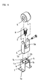
- Fig. 4 is an exploded perspective view showing structures for supporting wheels of a roller skate according to the present invention;
- Fig. 5 is a perspective view showing wheels extended from an outsole of the roller skate according to the invention; and
- Fig. 6 is a perspective view showing wheels retracted into the outsole of the roller skate according to the invention.
-
- Reference now should be made to the drawings, in which the same reference numerals are used throughout the different drawings to designate the same or similar components.
- Figs. 4 to 6 show structures for supporting wheels of a roller skate according to the present invention. As shown in the drawings, an
outsole 2 of a roller skate to which a structure according to the present invention is attached is formed withrectangular receiving rooms 2a at appropriate positions. Each of thereceiving rooms 2a receives abase frame 1 therein. Thebase frame 1 is shaped into a box shape with an upper side and a front or a rear side opened, and provided at its both upper ends with flanges 1a each having a screw hole. Theframe 1 can be fixedly attached to theoutsole 2 of the roller skate by tightening screws into theoutsole 2 through the screw holes. Theframe 1 is formed at its bottom surface with a pair ofprotrusions 1b which are slightly extended inwardly to face each other. Furthermore, the bottom surface of theframe 1 is formed at its both sides withfitting recesses 1c. Therefore, the bottom surface of theframe 1 has a "T"-shaped cut portion. A pair of vertical walls are provided at its front or rear side with hinge pins 4a, respectively, and aswing plate 4 is pivotally coupled to theframe 1 via the hinge pins 4a. Abracket 5 is rotatably coupled to theswing plate 4. - The
bracket 5 has a pair of arms extended downward, between which awheel 6 is rotatably supported. Thebracket 5 has at its top surface acrosswise protrusion 5a which is adapted to be releasably fitted in thefitting recesses 1c of theframe 1. Thebracket 5 is formed at its top wall with a counterbored throughhole 5b. Abolt stud 8 is threaded into the counterbored throughhole 5b through acoil spring 7 interposed therebetween so that thecoil spring 7 is disposed between a bolt head seat of thecounterbored hole 5b and a head of thebolt stud 8. - The
swing plate 4 is centrally formed with a threadedhole 4b such that a lower end of thebolt stud 8 can be releasably threaded into the threadedhole 4b. - Functions of the structure for supporting a wheel according to the invention will be described hereinafter.
- The
top protrusion 5a of thebracket 5 is fitted into thefitting recesses 1c formed at the lower end of theframe 1, and shoulders disposed at both sides of thetop protrusion 5a are engaged with theprotrusions 1b and the bottom surface of theframe 1, thereby preventing thebracket 5 from being moved back and forth. In addition, since thebracket 5 is upward biased by thecoil spring 7 interposed between thebracket 5 and thebolt stud 8, thebracket 5 can be more securely attached to theframe 1. - When the
wheel 6 or thebracket 5 is pulled out of theframe 1 by a pulling force exceeding a certain value, thetop protrusion 5a of thebracket 5 is taken out of thefitting recesses 1c of theframe 1 while compressing thecoil spring 7, thereby allowing thebracket 5 to be rotated about thebolt stud 8. When thebracket 5 is rotated 90° in a state of being out of thefitting recesses 1c, thetop protrusion 5a of thebracket 5 comes into contact with theswing plate 4 at its side. Thereafter, as theswing plate 4 is turned upward about the hinge pin 4a, thebracket 5 and thewheel 6 which are coupled to theswing plate 4 are received in thereceiving room 2a of theoutsole 2. When thebracket 5 is received in theroom 2a, thebracket 5 is closely fitted between the facingprotrusions 1b of theframe 1, thereby causing thewheel 6 to be maintained in thereceiving room 2a. - The
coil spring 7 is designed to have an elasticity sufficient to cause theswing plate 4 and thebracket 5 to be strongly coupled to each other. Theprotrusions 1b formed at the bottom end of theframe 1 are extended inwardly such that theprotrusions 1b have a predetermined spacing therebetween to allow the rotatedbracket 5 to be passed therethrough. - As described above, the present invention provides a structure for supporting a wheel of a roller skate which enables a bracket and a wheel to be retracted into a receiving room of an outsole of the roller skate easily and reliably by a simple operation of pulling and turning the bracket or the wheel 90° and then pushing it into the receiving room of the outsole. By carrying out the operation in reverse, the wheel can be extended from the receiving room without difficulty. Furthermore, since the bracket is subjected to elasticity of a coil spring, the top portion of the bracket can be coupled to a frame more stably and securely.
- Although a preferred embodiment of the present invention has been described for illustrative purposes, those skilled in the art will appreciate that various modifications, additions and substitutions are possible, without departing from the scope and spirit of the invention as disclosed in the accompanying claims.
Claims (2)
- A structure for supporting a wheel of a roller skate comprising:a frame attached to an outsole of the roller skate, which is shaped into a cubic body having upper and front or rear walls opened, and which has at its bottom wall a "T"shaped cut opening thereby causing a pair of fitting recesses and a pair of protrusions to be formed at both sides of the bottom wall;a swing plate pivotally coupled to both side walls of the frame to be in contact with an upper surface of the bottom wall, which has a central threaded hole; anda bracket for rotatably supporting a wheel, which has a through hole aligned with the central threaded hole of the swing plate, and a top portion to be releasably fitted in the pair of fitting recesses of the frame, the bracket being rotatably coupled to the swing plate by a bolt threaded in the threaded hole of the swing plate through the through hole of the bracket with a coil spring disposed between the bolt and the bracket, whereby the bracket can be retracted into the frame through the opened front or rear wall after the top protrusion of the bracket is pulled out of the fitting recesses of the frame and then rotated by an angle of 90°.
- The structure for supporting a wheel of a roller skate as set forth in claim 1, in which the bracket has a pair of arms extending downward which rotatably support the wheel therebetween, and a protrusion formed at the top portion thereof which is releasably fitted in the fitting recesses of the frame, and the through hole of the bracket is formed with a concentric counterbored portion receiving the coil spring therein.
Applications Claiming Priority (2)
| Application Number | Priority Date | Filing Date | Title |
|---|---|---|---|
| KR2020000032287U KR200222386Y1 (en) | 2000-11-18 | 2000-11-18 | structure of roller skate for roller supporting |
| KR2000032287 | 2000-11-18 |
Publications (2)
| Publication Number | Publication Date |
|---|---|
| EP1208882A2 true EP1208882A2 (en) | 2002-05-29 |
| EP1208882A3 EP1208882A3 (en) | 2003-05-28 |
Family
ID=19671786
Family Applications (1)
| Application Number | Title | Priority Date | Filing Date |
|---|---|---|---|
| EP01127572A Withdrawn EP1208882A3 (en) | 2000-11-18 | 2001-11-19 | Arrangement for supporting a wheel of a roller skate |
Country Status (4)
| Country | Link |
|---|---|
| US (1) | US20020060435A1 (en) |
| EP (1) | EP1208882A3 (en) |
| JP (1) | JP3086094U (en) |
| KR (1) | KR200222386Y1 (en) |
Families Citing this family (5)
| Publication number | Priority date | Publication date | Assignee | Title |
|---|---|---|---|---|
| JP2697801B2 (en) * | 1991-10-17 | 1998-01-14 | 株式会社クボタ | Septic tank |
| WO2000059323A1 (en) | 1999-04-01 | 2000-10-12 | Heeling Sports Limited | Heeling apparatus and method |
| US6631911B2 (en) * | 2001-05-30 | 2003-10-14 | Ching-Long Chen | Combined structure of a sports shoe and an in-line skate |
| US20090107008A1 (en) * | 2007-10-31 | 2009-04-30 | Yu-Chun Chou | Integral shoe with roller assembly |
| US10945485B2 (en) | 2012-08-03 | 2021-03-16 | Heeling Sports Limited | Heeling apparatus |
Citations (1)
| Publication number | Priority date | Publication date | Assignee | Title |
|---|---|---|---|---|
| KR200237495Y1 (en) | 2000-10-25 | 2001-10-25 | 김정재 | structure of roller skate for roller supporting |
Family Cites Families (5)
| Publication number | Priority date | Publication date | Assignee | Title |
|---|---|---|---|---|
| US584089A (en) * | 1897-06-08 | Julius buttermilch | ||
| US2719724A (en) * | 1953-08-11 | 1955-10-04 | Lundgren Robert | Roller skate with spring biased steerably interconnected tandem wheels |
| IT1226672B (en) * | 1988-12-28 | 1991-01-31 | Sisler Remo | SELF-DIFFERENTIZING DEVICE FOR MANUAL DRIVE TROLLEY WHEELS |
| US6065762A (en) * | 1998-03-11 | 2000-05-23 | Brelvi; Nazir A | Multidirectional in-line roller skate |
| US6120039A (en) * | 1999-08-16 | 2000-09-19 | Clementi; Fred | Walking and in-line skate shoe |
-
2000
- 2000-11-18 KR KR2020000032287U patent/KR200222386Y1/en not_active IP Right Cessation
-
2001
- 2001-11-16 JP JP2001007519U patent/JP3086094U/en not_active Expired - Fee Related
- 2001-11-19 US US09/995,981 patent/US20020060435A1/en not_active Abandoned
- 2001-11-19 EP EP01127572A patent/EP1208882A3/en not_active Withdrawn
Patent Citations (1)
| Publication number | Priority date | Publication date | Assignee | Title |
|---|---|---|---|---|
| KR200237495Y1 (en) | 2000-10-25 | 2001-10-25 | 김정재 | structure of roller skate for roller supporting |
Also Published As
| Publication number | Publication date |
|---|---|
| EP1208882A3 (en) | 2003-05-28 |
| KR200222386Y1 (en) | 2001-05-02 |
| US20020060435A1 (en) | 2002-05-23 |
| JP3086094U (en) | 2002-05-31 |
Similar Documents
| Publication | Publication Date | Title |
|---|---|---|
| US7748680B2 (en) | Foldable stand for display device | |
| US7240685B2 (en) | Side rail assembly for a canopy including a side rail having a hook for engaging a side rail connector on an upright of the canopy | |
| US6449780B1 (en) | Combined adult and children's toilet seat assembly | |
| US6200062B1 (en) | Furniture combination with connector device | |
| US20070137534A1 (en) | Flip top table | |
| US5024359A (en) | Bicycle cooler | |
| US6484991B2 (en) | Hanger support with vertically disposed garment hanging groves | |
| US20050193520A1 (en) | Door stop | |
| US20060261230A1 (en) | Device for removing diseased surface tissues | |
| US4744126A (en) | Combined pull and carry handle | |
| US20050061940A1 (en) | Retractable hook assembly for mounting on a surface | |
| EP1208882A2 (en) | Arrangement for supporting a wheel of a roller skate | |
| US6003691A (en) | Tool rack | |
| USD467400S1 (en) | Clothes peg | |
| US6282827B1 (en) | Picture frame and stand therefor | |
| US20020000500A1 (en) | Golf bag support device | |
| US5876289A (en) | Safety swing seat mounting structure | |
| US6739474B1 (en) | Garbage can for use in an automobile | |
| US6598240B1 (en) | Toilet seat device having support for children | |
| US20030048051A1 (en) | Silding track structure | |
| KR200386688Y1 (en) | Apparatus for window lock | |
| EP1059046A1 (en) | Bag having cellular phone receiving structure | |
| JP3031911B2 (en) | Casing used for locking device during earthquake and storage box using the casing | |
| KR900009437Y1 (en) | Hinge of portable table | |
| JP3008686U (en) | Golf bag support frame |
Legal Events
| Date | Code | Title | Description |
|---|---|---|---|
| PUAI | Public reference made under article 153(3) epc to a published international application that has entered the european phase |
Free format text: ORIGINAL CODE: 0009012 |
|
| AK | Designated contracting states |
Kind code of ref document: A2 Designated state(s): AT BE CH CY DE DK ES FI FR GB GR IE IT LI LU MC NL PT SE TR |
|
| AX | Request for extension of the european patent |
Free format text: AL;LT;LV;MK;RO;SI |
|
| PUAL | Search report despatched |
Free format text: ORIGINAL CODE: 0009013 |
|
| AK | Designated contracting states |
Designated state(s): AT BE CH CY DE DK ES FI FR GB GR IE IT LI LU MC NL PT SE TR |
|
| AX | Request for extension of the european patent |
Extension state: AL LT LV MK RO SI |
|
| AKX | Designation fees paid | ||
| REG | Reference to a national code |
Ref country code: DE Ref legal event code: 8566 |
|
| STAA | Information on the status of an ep patent application or granted ep patent |
Free format text: STATUS: THE APPLICATION IS DEEMED TO BE WITHDRAWN |
|
| 18D | Application deemed to be withdrawn |
Effective date: 20031129 |