EP1203675A2 - Apparatus and method for alarming decrease in tyre air pressure - Google Patents
Apparatus and method for alarming decrease in tyre air pressure Download PDFInfo
- Publication number
- EP1203675A2 EP1203675A2 EP01309203A EP01309203A EP1203675A2 EP 1203675 A2 EP1203675 A2 EP 1203675A2 EP 01309203 A EP01309203 A EP 01309203A EP 01309203 A EP01309203 A EP 01309203A EP 1203675 A2 EP1203675 A2 EP 1203675A2
- Authority
- EP
- European Patent Office
- Prior art keywords
- judged
- issuing
- threshold
- preliminary alarm
- decrease
- Prior art date
- Legal status (The legal status is an assumption and is not a legal conclusion. Google has not performed a legal analysis and makes no representation as to the accuracy of the status listed.)
- Granted
Links
Images


Classifications
-
- B—PERFORMING OPERATIONS; TRANSPORTING
- B60—VEHICLES IN GENERAL
- B60C—VEHICLE TYRES; TYRE INFLATION; TYRE CHANGING; CONNECTING VALVES TO INFLATABLE ELASTIC BODIES IN GENERAL; DEVICES OR ARRANGEMENTS RELATED TO TYRES
- B60C23/00—Devices for measuring, signalling, controlling, or distributing tyre pressure or temperature, specially adapted for mounting on vehicles; Arrangement of tyre inflating devices on vehicles, e.g. of pumps or of tanks; Tyre cooling arrangements
- B60C23/06—Signalling devices actuated by deformation of the tyre, e.g. tyre mounted deformation sensors or indirect determination of tyre deformation based on wheel speed, wheel-centre to ground distance or inclination of wheel axle
- B60C23/061—Signalling devices actuated by deformation of the tyre, e.g. tyre mounted deformation sensors or indirect determination of tyre deformation based on wheel speed, wheel-centre to ground distance or inclination of wheel axle by monitoring wheel speed
Definitions
- the present invention relates to an apparatus and method for alarming decrease in tyre air pressure. More particularly, the present invention relates to an apparatus and method for alarming decrease in tyre air pressure capable of properly informing a decompressed condition of a tyre to a driver of a vehicle such that the driver can drive safely.
- F1 to F4 are the rotational angular velocities of front left tyre, front right tyre, rear left tyre and rear right tyre, respectively.
- the threshold is set so that decompression of a tyre by 30% from normal internal pressure is surely detected, the driver is alarmed of decompression when the internal pressure has decrease by approximately 30%.
- the present invention has been made in view of the above circumstances, and it is an object thereof to provide an apparatus and method for alarming decrease in tyre air pressure capable of properly informing a decompressed condition of a tyre to a driver of a vehicle such that the driver might drive safely.
- an apparatus for alarming decrease in tyre air pressure based on rotational information obtained from tyres attached to a vehicle comprising a rotational information detecting means for detecting rotational information of the respective tyres; a rotation information memory means for storing the rotational information of the respective tyres; a judged value calculating means for calculating judged values based on the rotational information of the respective tyres; a judged value memory means for storing the judged values; a transition calculating means for calculating transition of the judged values based on the stored judged values; a judging means for determining a decrease in tyre air pressure based on the judged values; and an alarming means for issuing preliminary alarm prior to issuing a predetermined alarm for informing decrease in internal pressure based on the transition of the judged values in case the judged value tends to move to exceed a predetermined threshold for determining a decrease in internal pressure.
- a method for alarming decrease in tyre air pressure based on rotational information obtained from tyres attached to a vehicle comprising the steps of detecting rotational information of the respective tyres; storing the rotational information of the respective tyres; calculating judged values based on the rotational information of the respective tyres; storing the judged values; calculating transition of the judged values based on the stored judged values; determining a decrease in tyre air pressure based on the judged values; and issuing preliminary alarm prior to issuing a predetermined alarm for informing decrease in internal pressure based on the transition of the judged values in case the judged value tends to move to exceed a predetermined threshold for determining a decrease in internal pressure.
- the apparatus for alarming decrease in air pressure is for detecting whether the air pressure of any of four wheels W1, W2, W3 and W4 (W1: front left tyre, W2: front right tyre, W3: rear left tyre, and W4: rear right tyre, hereinafter referred generally to as Wi) attached to a four wheels vehicle has decreased or not, and comprises rotational information detecting means 1, which is an ordinary wheel speed sensor, respectively arranged in connection with each of the tyres Wi.
- the rotational information detecting means 1 is not particularly limited in the present invention so long as it can detect rotational information, for example, the number of revolutions, rotational speed, angular velocity or the like of each of the tyres.
- the rotational information detecting means 1 might be a wheel speed sensor for generating rotational pulses by using an electromagnetic pickup or similar device to obtain wheel speeds (rotational speeds) on the basis of the number of pulses, or an angular velocity sensor including those in which electricity is generated by utilising rotation such as a dynamo to obtain the wheel speed on the basis of the generated voltage thereof.
- Outputs of the rotational information detecting means 1 are supplied to a control unit 2 which may be an ABS or a separate control unit.
- a display means 3 which is an alarming means, composed of liquid crystal display elements, plasma display elements, or CRT for informing which tyre Wi has decreased pressure, and an initialisation switch 4 which can be operated by the driver.
- the control unit 2 comprises, as shown in Figure 2, an I/O interface 2a required for sending/receiving signals to/from an external device, a CPU 2b which functions as a centre of calculation, a ROM 2c which stores a control operation program for the CPU 2b, and a RAM 2d into which data is temporarily written and are read out therefrom when the CPU 2b performs control operations.
- the apparatus comprises a rotational information detecting means for detecting rotational information of the respective tyres, a rotational information memory means for storing the rotational information of the respective tyres, a judged value calculating means for calculating judged values based on the rotational information of the respective tyres, a buffer for accumulating judged values which is a judged value memory means for storing the judged values, a transition calculating means for calculating transition of the judged values based on the stored judged values, a judging means for determining a decrease in tyre air pressure based on the judged values, and an alarming means for issuing preliminary alarm prior to issuing a predetermined alarm for informing decrease in internal pressure based on the transition of the judged values in case the judged value tends to move to exceed a predetermined threshold for determining a decrease in internal pressure.
- the control unit 2 comprises the judged value memory means, the buffer for accumulating judged values, the judged value calculating means, the transition calculating means and the judging means.
- the judging means includes a circuit for setting a first threshold for issuing a preliminary alarm at a smaller level than the predetermined threshold and a second threshold for issuing a preliminary alarm for indicating a predetermined number by which the judged values has consecutively exceeded the first threshold for issuing preliminary alarm.
- the judging means further includes a first condition providing that the judged value is not less than the first threshold for issuing preliminary alarm and a second condition providing that a summed value which is accumulated in the judged value memory means is not less than a product of the first threshold for issuing preliminary alarm and the second threshold for issuing preliminary alarm.
- the alarming means further includes a preliminary alarm circuit for adding, in case the first condition is met, the judged value to the judged value memory means while giving, in case the second condition is met, a command to issue a preliminary alarm.
- rotational information detecting means 1 pulse signals corresponding to numbers of rotation of each tyre Wi ( hereinafter referred to as "wheel speed pulse”) are outputted.
- rotational angular velocities F 1 of the respective tyres Wi are calculated at predetermined sampling periods ⁇ T(sec), for instance, every ⁇ T of 1 second based on the wheel speed pulse outputted from the rotational information detecting means 1.
- V (V1 + V2 + V3 + V4)/4
- the judged values are stored and summed, and a preliminary alarm is issued if the transition of the judged values tends to move to exceed the threshold for decompression.
- a first threshold for issuing a preliminary alarm S1 and a second threshold for issuing preliminary alarm S2 are set in the period between calculation of judged values during running and issuing alarm upon determination of decompression in a predetermined manner, and the following first condition and second condition are set.
- the judged value is not less than the first threshold for issuing a preliminary alarm S1.
- Second condition the value of the buffer for accumulating judged values (summed value of judged values) is not less than a product of the first threshold for issuing preliminary alarm S1 and the second threshold for issuing preliminary alarm S2 (S1xS2).
- the first threshold for issuing the preliminary alarm S is set to be a value which is smaller than the predetermined threshold S.
- the second threshold for issuing a preliminary alarm S2 might represent a degree thereof.
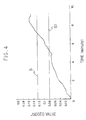
- a Mercedes Benz A Class type vehicle (A160) equipped with tyres (tyre sizes: 185/65R15) at normal air pressure (21.6x10 4 Pa) was provided.
- the sampling time for the wheel speed was set to 5 seconds while the predetermined threshold S was set to 0.125, the first threshold for issuing preliminary alarm S1 to 0.08 and the second threshold for issuing preliminary alarm S2 to 12.
- the resultant transition of judged values is illustrated in Figure 4.
- the judged values were accumulated and when these judged values were not less than the first threshold for issuing a preliminary alarm 0.08 (S1), and in the case of judged value for issuing preliminary alarm which is a sum of judged values, exceeded a product of the first threshold for issuing preliminary alarm 0.08 (S1) and the second threshold for issuing preliminary alarm 12 (S2), namely 0.96, it was further determined that the tyre tends to move to exceed the predetermined threshold S, and a preliminary alarm was accordingly issued after 374 seconds (6.23 minutes) from the start of running.
- the normal alarm for indicating decompression which is based only on the predetermined threshold was issued 60 seconds later, that is, after 434 seconds (7.23 minutes) from the start of running.
Abstract
Description
and i: 1 = front left tyre, 2 - front right tyre, 3 = rear left tyre, 4 = rear right tyre.
Claims (6)
- An apparatus for alarming decrease in tyre air pressure based on rotational information obtained from tyres (Wi) attached to a vehicle, comprising a rotational information detecting means (1) for detecting rotational information of the respective tyres (Wi); a rotational information memory means for storing the rotational information of the respective tyres (Wi); a judged value calculating means for calculating judged values based on the rotation information of the respective tyres; a judged value memory means for storing the judged values; characterised by a transition calculating means for calculating transition of the judged values based on the stored judged values; a judging means for determining a decrease in tyre air pressure based on the judged values; and an alarming means for issuing preliminary alarm prior to issuing a predetermined alarm for informing decrease in internal pressure based on the transition of the judged values in case the judged value tends to move to exceed a predetermined threshold for determining a decrease in internal pressure.
- An apparatus according to claim 1, characterised in that the judging means includes a circuit for setting a first threshold for issuing a preliminary alarm which is smaller than the predetermined threshold and a second threshold for issuing a preliminary alarm for indicating a predetermined number by which the judged values has consecutively exceeded the first threshold for issuing a preliminary alarm.
- An apparatus according to claim 2, characterised in that the judging means further includes a first condition providing that the judged value is not less than the first threshold for issuing a preliminary alarm and a second condition providing that a summed value which is accumulated in the judged value memory means is not less than a product of the first threshold for issuing a preliminary alarm and the second threshold for issuing a preliminary alarm, and wherein the alarming means further includes a preliminary alarm circuit for adding, in case the first condition is met, the judged value to the judged value memory means while giving, in case the second condition is met, a command for issuing a preliminary alarm.
- A method for alarming decrease in tyre air pressure based on rotational information obtained from tyres attached to a vehicle, comprising the step of detecting rotation information of the respective tyres (Wi); storing the rotational information of the respective tyres; calculating judged values based on the rotational information of the respective tyres; storing the judged values; characterised by calculating transition of the judged values based on the stored judged values; determining a decrease in tyre air pressure based on the judged values; and issuing a preliminary alarm prior to issuing a predetermined alarm for informing decrease in internal pressure based on the transition of the judged values in case the judged value tends to move to exceed a predetermined threshold (S1) for determining a decrease in internal pressure.
- A method according to claim 4, characterised in that when issuing a preliminary alarm, there are used a first threshold (S1) for issuing a preliminary alarm which is smaller than the predetermined threshold and a second threshold (S2) for issuing the preliminary alarm for indicating a predetermined number by which the judged values has consecutively exceeded the first threshold (S1) for issuing preliminary alarm.
- A method according to claim 5, characterised in that there are set a first condition providing that the judged value is not less than the first threshold (S1) for issuing a preliminary alarm and a second condition providing that a summed value which is accumulated in the judged value memory means is not less than a product of the first threshold (S1) for issuing a preliminary alarm and the second threshold (S2) for issuing a preliminary alarm, and wherein the judged value is stored and added in case the judged value meets the first condition, and then a preliminary alarm is issued in the case where the added value meets the second condition.
Applications Claiming Priority (2)
| Application Number | Priority Date | Filing Date | Title |
|---|---|---|---|
| JP2000333959 | 2000-10-31 | ||
| JP2000333959A JP2002141848A (en) | 2000-10-31 | 2000-10-31 | Radio repeater |
Publications (3)
| Publication Number | Publication Date |
|---|---|
| EP1203675A2 true EP1203675A2 (en) | 2002-05-08 |
| EP1203675A3 EP1203675A3 (en) | 2003-01-08 |
| EP1203675B1 EP1203675B1 (en) | 2009-12-23 |
Family
ID=18809957
Family Applications (1)
| Application Number | Title | Priority Date | Filing Date |
|---|---|---|---|
| EP20010309203 Expired - Lifetime EP1203675B1 (en) | 2000-10-31 | 2001-10-30 | Apparatus and method for alarming decrease in tyre air pressure |
Country Status (3)
| Country | Link |
|---|---|
| EP (1) | EP1203675B1 (en) |
| JP (1) | JP2002141848A (en) |
| DE (1) | DE60140847D1 (en) |
Cited By (6)
| Publication number | Priority date | Publication date | Assignee | Title |
|---|---|---|---|---|
| EP1396356A1 (en) * | 2002-09-06 | 2004-03-10 | Sumitomo Rubber Industries Ltd. | Method and apparatus for detecting decrease in tire air-pressure and program for judging decompression of tire |
| WO2008113379A1 (en) * | 2007-03-16 | 2008-09-25 | Nira Dynamics Ab | Method, system and computer program of issuing a tire pressure deviation warning |
| US8151127B2 (en) | 2000-07-26 | 2012-04-03 | Bridgestone Americas Tire Operations, Llc | System for conserving battery life in a battery operated device |
| US8266465B2 (en) | 2000-07-26 | 2012-09-11 | Bridgestone Americas Tire Operation, LLC | System for conserving battery life in a battery operated device |
| TWI766022B (en) * | 2017-05-30 | 2022-06-01 | 德商安博歐葛斯特布雷米克索尼公司 | Mobile alarm apparatus |
| WO2023214003A1 (en) * | 2022-05-05 | 2023-11-09 | Nira Dynamics Ab | Methods, apparatuses and computer program products for determining the severity of a deflation of a tire |
Families Citing this family (3)
| Publication number | Priority date | Publication date | Assignee | Title |
|---|---|---|---|---|
| JP4567480B2 (en) * | 2005-02-04 | 2010-10-20 | 富士通株式会社 | Signal transmission system and signal transmission method |
| JP2007005908A (en) * | 2005-06-21 | 2007-01-11 | Murata Mfg Co Ltd | Wireless communication apparatus |
| JP5163527B2 (en) * | 2009-02-12 | 2013-03-13 | 富士通株式会社 | Amplifier |
Family Cites Families (4)
| Publication number | Priority date | Publication date | Assignee | Title |
|---|---|---|---|---|
| GB2226434A (en) * | 1988-12-23 | 1990-06-27 | Manuel Alfred Xavier Cocheme | Monitoring system for vehicle tyres |
| JP3286434B2 (en) * | 1993-12-10 | 2002-05-27 | 住友ゴム工業株式会社 | Tire pressure drop warning device |
| US5721528A (en) * | 1996-12-23 | 1998-02-24 | Ford Global Technologies, Inc. | Low tire warning system |
| JP2000099869A (en) * | 1998-09-21 | 2000-04-07 | Toyota Motor Corp | Tire inflation pressure monitor |
-
2000
- 2000-10-31 JP JP2000333959A patent/JP2002141848A/en active Pending
-
2001
- 2001-10-30 EP EP20010309203 patent/EP1203675B1/en not_active Expired - Lifetime
- 2001-10-30 DE DE60140847T patent/DE60140847D1/en not_active Expired - Lifetime
Non-Patent Citations (1)
| Title |
|---|
| None |
Cited By (7)
| Publication number | Priority date | Publication date | Assignee | Title |
|---|---|---|---|---|
| US8151127B2 (en) | 2000-07-26 | 2012-04-03 | Bridgestone Americas Tire Operations, Llc | System for conserving battery life in a battery operated device |
| US8266465B2 (en) | 2000-07-26 | 2012-09-11 | Bridgestone Americas Tire Operation, LLC | System for conserving battery life in a battery operated device |
| EP1396356A1 (en) * | 2002-09-06 | 2004-03-10 | Sumitomo Rubber Industries Ltd. | Method and apparatus for detecting decrease in tire air-pressure and program for judging decompression of tire |
| US7032442B2 (en) | 2002-09-06 | 2006-04-25 | Sumitomo Rubber Industries, Ltd. | Method and apparatus for detecting decrease in tire air-pressure and program for judging decompression of tire |
| WO2008113379A1 (en) * | 2007-03-16 | 2008-09-25 | Nira Dynamics Ab | Method, system and computer program of issuing a tire pressure deviation warning |
| TWI766022B (en) * | 2017-05-30 | 2022-06-01 | 德商安博歐葛斯特布雷米克索尼公司 | Mobile alarm apparatus |
| WO2023214003A1 (en) * | 2022-05-05 | 2023-11-09 | Nira Dynamics Ab | Methods, apparatuses and computer program products for determining the severity of a deflation of a tire |
Also Published As
| Publication number | Publication date |
|---|---|
| JP2002141848A (en) | 2002-05-17 |
| EP1203675B1 (en) | 2009-12-23 |
| DE60140847D1 (en) | 2010-02-04 |
| EP1203675A3 (en) | 2003-01-08 |
Similar Documents
| Publication | Publication Date | Title |
|---|---|---|
| EP1880875B1 (en) | Method, apparatus and program for alarming decrease in tire air-pressure | |
| JP4463311B2 (en) | Tire pressure drop detection method and apparatus, and tire decompression determination program | |
| EP1167086B1 (en) | Method for alarming decrease in tyre air pressure and apparatus used therefor | |
| US5923244A (en) | Method of detecting a deflated tire on a vehicle | |
| EP2529957B1 (en) | System, method and program for detecting deflated tires | |
| EP0908331B1 (en) | Apparatus for alarming decrease in tyre air-pressure and method thereof | |
| US6501373B2 (en) | Apparatus and method for alarming decrease in tire air-pressure | |
| EP1190874B1 (en) | Apparatus and method for alarming decrease in tyre air pressure | |
| EP1203675A2 (en) | Apparatus and method for alarming decrease in tyre air pressure | |
| EP0897815B1 (en) | Tyre air-pressure abnormality alarm device and method thereof | |
| EP1795379B1 (en) | Apparatus, method and program for alarming abnormality in tire air-pressure | |
| EP1396356A1 (en) | Method and apparatus for detecting decrease in tire air-pressure and program for judging decompression of tire | |
| EP1215057B1 (en) | Method and apparatus for alarming decrease in tire air-pressure | |
| EP1361081B1 (en) | Method and apparatus for detecting decrease in tire air-pressure, and program for judging decompression of tire | |
| JPH08501040A (en) | Method for detecting a decompressed tire in a vehicle | |
| EP1284205B1 (en) | Method and apparatus for detecting decrease in tire air-pressure, and selecting program for thresholds for judging decompression of tire | |
| EP1306235B1 (en) | Method and apparatus for detecting decrease in tire air-pressure | |
| US20030128110A1 (en) | Method of detection of limited slip differential device, method and apparatus for detecting decrease in tire air-pressure employing the method of detection, and program for judging decompression of tire | |
| EP1798078B1 (en) | Apparatus, method and program for alarming abnormality in tire air-pressure | |
| JP4028848B2 (en) | Tire pressure drop detection method and apparatus, and tire decompression determination program | |
| JP2002362121A (en) | Tire pneumatic pressure drop detecting method and device as well as tire pneumatic pressure drop determining program | |
| JP3605006B2 (en) | Tire pressure drop warning device and method | |
| JP2005205977A (en) | Tire pneumatic pressure lowering detection method and device, and program of tire decompression determination | |
| JP2001163021A (en) | Method and device for warning lowering of tire inflation pressure |
Legal Events
| Date | Code | Title | Description |
|---|---|---|---|
| PUAI | Public reference made under article 153(3) epc to a published international application that has entered the european phase |
Free format text: ORIGINAL CODE: 0009012 |
|
| AK | Designated contracting states |
Kind code of ref document: A2 Designated state(s): AT BE CH CY DE DK ES FI FR GB GR IE IT LI LU MC NL PT SE TR |
|
| AX | Request for extension of the european patent |
Free format text: AL;LT;LV;MK;RO;SI |
|
| PUAL | Search report despatched |
Free format text: ORIGINAL CODE: 0009013 |
|
| AK | Designated contracting states |
Kind code of ref document: A3 Designated state(s): AT BE CH CY DE DK ES FI FR GB GR IE IT LI LU MC NL PT SE TR |
|
| AX | Request for extension of the european patent |
Free format text: AL;LT;LV;MK;RO;SI |
|
| 17P | Request for examination filed |
Effective date: 20030630 |
|
| AKX | Designation fees paid |
Designated state(s): DE FR GB |
|
| 17Q | First examination report despatched |
Effective date: 20061128 |
|
| GRAP | Despatch of communication of intention to grant a patent |
Free format text: ORIGINAL CODE: EPIDOSNIGR1 |
|
| GRAS | Grant fee paid |
Free format text: ORIGINAL CODE: EPIDOSNIGR3 |
|
| GRAA | (expected) grant |
Free format text: ORIGINAL CODE: 0009210 |
|
| RAP1 | Party data changed (applicant data changed or rights of an application transferred) |
Owner name: SUMITOMO ELECTRIC INDUSTRIES, LTD Owner name: SUMITOMO RUBBER INDUSTRIES, LTD. |
|
| AK | Designated contracting states |
Kind code of ref document: B1 Designated state(s): DE FR GB |
|
| REG | Reference to a national code |
Ref country code: GB Ref legal event code: FG4D |
|
| REF | Corresponds to: |
Ref document number: 60140847 Country of ref document: DE Date of ref document: 20100204 Kind code of ref document: P |
|
| PLBE | No opposition filed within time limit |
Free format text: ORIGINAL CODE: 0009261 |
|
| STAA | Information on the status of an ep patent application or granted ep patent |
Free format text: STATUS: NO OPPOSITION FILED WITHIN TIME LIMIT |
|
| 26N | No opposition filed |
Effective date: 20100924 |
|
| GBPC | Gb: european patent ceased through non-payment of renewal fee |
Effective date: 20101030 |
|
| PG25 | Lapsed in a contracting state [announced via postgrant information from national office to epo] |
Ref country code: GB Free format text: LAPSE BECAUSE OF NON-PAYMENT OF DUE FEES Effective date: 20101030 |
|
| REG | Reference to a national code |
Ref country code: FR Ref legal event code: PLFP Year of fee payment: 16 |
|
| REG | Reference to a national code |
Ref country code: FR Ref legal event code: PLFP Year of fee payment: 17 |
|
| REG | Reference to a national code |
Ref country code: FR Ref legal event code: PLFP Year of fee payment: 18 |
|
| PGFP | Annual fee paid to national office [announced via postgrant information from national office to epo] |
Ref country code: FR Payment date: 20180913 Year of fee payment: 18 |
|
| PGFP | Annual fee paid to national office [announced via postgrant information from national office to epo] |
Ref country code: DE Payment date: 20181016 Year of fee payment: 18 |
|
| REG | Reference to a national code |
Ref country code: DE Ref legal event code: R119 Ref document number: 60140847 Country of ref document: DE |
|
| PG25 | Lapsed in a contracting state [announced via postgrant information from national office to epo] |
Ref country code: DE Free format text: LAPSE BECAUSE OF NON-PAYMENT OF DUE FEES Effective date: 20200501 |
|
| PG25 | Lapsed in a contracting state [announced via postgrant information from national office to epo] |
Ref country code: FR Free format text: LAPSE BECAUSE OF NON-PAYMENT OF DUE FEES Effective date: 20191031 |