EP1202494A2 - Method and system for remotely maintaining and provisioning equipment over a wide area network - Google Patents
Method and system for remotely maintaining and provisioning equipment over a wide area network Download PDFInfo
- Publication number
- EP1202494A2 EP1202494A2 EP01125899A EP01125899A EP1202494A2 EP 1202494 A2 EP1202494 A2 EP 1202494A2 EP 01125899 A EP01125899 A EP 01125899A EP 01125899 A EP01125899 A EP 01125899A EP 1202494 A2 EP1202494 A2 EP 1202494A2
- Authority
- EP
- European Patent Office
- Prior art keywords
- media
- customer
- signal
- port
- data
- Prior art date
- Legal status (The legal status is an assumption and is not a legal conclusion. Google has not performed a legal analysis and makes no representation as to the accuracy of the status listed.)
- Withdrawn
Links
Images


Classifications
-
- H—ELECTRICITY
- H04—ELECTRIC COMMUNICATION TECHNIQUE
- H04L—TRANSMISSION OF DIGITAL INFORMATION, e.g. TELEGRAPHIC COMMUNICATION
- H04L12/00—Data switching networks
- H04L12/28—Data switching networks characterised by path configuration, e.g. LAN [Local Area Networks] or WAN [Wide Area Networks]
- H04L12/2854—Wide area networks, e.g. public data networks
-
- H—ELECTRICITY
- H04—ELECTRIC COMMUNICATION TECHNIQUE
- H04L—TRANSMISSION OF DIGITAL INFORMATION, e.g. TELEGRAPHIC COMMUNICATION
- H04L61/00—Network arrangements, protocols or services for addressing or naming
-
- H—ELECTRICITY
- H04—ELECTRIC COMMUNICATION TECHNIQUE
- H04L—TRANSMISSION OF DIGITAL INFORMATION, e.g. TELEGRAPHIC COMMUNICATION
- H04L61/00—Network arrangements, protocols or services for addressing or naming
- H04L61/09—Mapping addresses
- H04L61/10—Mapping addresses of different types
Definitions
- the present invention relates generally to the field of broadband multi-media communication systems. More specifically, the invention is a system and method for managing, provisioning and troubleshooting customer located equipment.
- Broadband and multimedia service providers are in the business of providing access to a service or groups of services for a fee, usually a monthly fee, but unit fees are not uncommon. For the charge, the service provider authorizes a customer for a service.
- most service providers specialized in only one service, i.e. telephone, Internet access, cable television programming, etc., possibly due to delivery expense resulting from limited bandwidth media, dissimilar transmission media and incompatible delivery protocols.
- the individual services were piped to a customer's business or residence on a separate transmission media including coaxial cable or twisted pair wires. While it was always possible for a provider to cover the ground with more than one type of transmission media, thereby selling multiple services to a customer, the customer was always faced with the problems associated with multiple interfaces. Even in cases where a single transmission media accessed multiple services, such as telephone service and Internet from the same twisted pair wires, the transmission protocols were often incompatible forcing the customer to subscribe to multiple sets of media and two telephone lines.
- an interface can be any number of devices used by the customer to connect to a service, for example, dial-up modems, high speed modems, digital subscriber line (DSL), high speed switches, routers and a variety of set-top boxes for provisioning television, telephone and Internet services.
- DSL digital subscriber line
- Troubleshooting usually entails the service provider sending a technician to the customer's site to ascertain the complaint and investigate any problems with the interface. Very often the interface is owned by the service provider and leased, with the service, to the customer. Even in the best situations where problems can be resolved telephonically, it requires a frustrated customer to describe the problem to the services provider's technical support representative.
- the cause of the customer's problem may be located in the service provider's equipment, the customer's equipment or both.
- the support person must try to understand the problem as described by the customer, and then take corrective measures from the help site. Then, based on the customer's assessment of the repair attempt, the support person attempts other solutions until the problem has been solved or localized at the customer's equipment.
- the service person If the problem cannot be corrected telephonically, the service person writes a service request for onsite maintenance of the customer located equipment. A mobile service representative then schedules an appointment with the customer, at which time the diagnostic procedures performed by the help desk representative are recreated at the customer's site.
- the present invention relates to a method and system for managing, provisioning and troubleshooting remote customer located equipment.
- the system includes a customer located network interface device which provides broadband data media or multi media connections to a customer.
- the network interface device may take the form of a network switch, router, fiber to the home network unit or the like.
- the network interface device monitors data media for data packets address to the device.
- the device routes data packets that are IP-addressed to the network interface device.
- the device captures packets based on the destination Ethernet type, those packets wrapped in the Ethernet type of the network interface device are captured, while packets wrapped in the customer's Ethernet type are passed to a media output port for the customer.
- the network interface device further contains one or more media switches connected to various media ports along with control and status logic for operating the media switches.
- Data packets that are destined for the network interface device may contain control and status requests for operating and monitoring the state of the individual switches.
- the service provider communicates with the device over a WAN, such as the Internet, using a common web browser. Individual network interface devices are uniquely addressable from the browser and security is enhanced between the device and service provider by encrypting the data packets. A service provider is thus able to remotely manage provision and troubleshoot the network interface device even when physically inaccessible while located at a customer site.
- network 100 is a diagram illustrating a connection between a WAN (wide area network) such as the Internet, to a plurality of LANs (local area networks) and subnets for transmitting information packets to individual clients serviced by the various LANs and subnets.
- WAN wide area network
- LANs local area networks
- router 110 provides a means for routing packets from the WAN to the various LANs and sub-nets in network 100 .
- a router is a device that forwards data packets from one local area network (LAN) or wide area network (WAN) to another. Based on routing tables and routing protocols, a router inspects only the network portion (netid or network address) of the address and directs incoming datagrams (data frames or data packets) to the appropriate outgoing router port.
- the routing protocol used by the router is a set of hardware and software standards that govern functionality of and between routers. Routing protocols are used by a router to determine the next node to transfer a data packet based on the best path to forward the packet toward its final destination.
- the router uses the routing protocol to determine which node to send the datagram based on the most expedient route (traffic load, line costs, speed, bad lines, etc.).
- a routing protocol also specifies how routers report changes and share information with other routers reachable in a network. This information is used to populate routing tables. Routing protocol dynamically adjusts routing decisions based on changing conditions.
- Well known routing protocols include RIP (routing information protocol), OSPF (open shortest path first), IGRP (interior gateway routing protocol), EGP (exterior gateway protocol) and BGP (border gateway protocol).
- routers function at the network/IP layer or OSI (open system interconnection) layer 3 of the communications protocol stack or suite.
- a communications protocol is a set of hardware and software standards that govern transmission between two communications devices.
- a protocol stack may consist of several layers, or levels of protocol functionality. Table I below lists some major communications protocol and the corresponding OSI layer in which a protocol functions. Protocols in parentheses are the protocol stack to which a protocol belongs.
- OSI Layer Protocol 1 RS-232 V.35 SONET 1-2 802.11 wireless Bluetooth wireless 2 Ethernet Fast Ethernet Gigabit Ethernet Token Ring FDDI ATM 3 IP (TCP/IP) IPX (NetWare) 4 SPX (NetWare) TCP (TCP/IP) UDP (TCP/IP) NetBEUI (NetBIOS) 5 NetBIOS 6 ASN.1 7 SMB (NetBEUI) AFP (AppleTalk) NCP (NetWare) NFS (TCP/IP) HTTP (TCP/IP) FTP (TCP/IP) SMTP (TCP/IP) DNS (TCP/IP)
- TCP/IP transmission control protocol/internet protocol
- HTTP hypertext transport protocol
- FTP file transfer protocol
- SMTP simple mail transfer protocol
- the Internet uses TCP/IP, HTTP, FTP and SMTP protocols.
- LANs mostly Ethernet, but also Token Ring and FDDI (fiber distributed data interface), provide the access method (layers 1 and 2) that moves packets from one physical station to another.
- Higher layer protocols such as TCP/IP, SPX/IPX (sequenced packet exchange/internetwork packet exchange) and NetBIOS/NetBEUI, are used in layers 3, 4 and 5 of the protocol stack to control and route the transmission.
- the precise model of the protocol stack is unimportant for the description herein, however it should be recognized that network devices have been traditionally designed to work in a particular layer or range of layers.
- the present invention may be implemented in a variety of communications protocols which are well known in the art, such as TCP/IP, SNA (systems network architecture) and OSI, or may instead be implemented in any other communications protocol.
- routers such as routers 110 and 112 have been used to segment LANs in order to balance traffic within workgroups and/or to filter traffic for security purposes and policy management. Routers are also used extensively at the edge of a network to connect remote sites to the network as shown by the position of router 110 in network 100. Routers can, however, only route a message that is transmitted by a routable protocol such as IP or IPX. Messages in non-routable protocols, such as NetBIOS and LAT, cannot be routed, but they can be transferred from LAN to LAN via a bridge (a device that connects two LAN segments together, which may be of similar or dissimilar LAN types). However, all routable protocols are not standardized so many modern routers (multiprotocol routers) support multiple non-standardized, communications protocols.
- router 110 maintains a list of all LANs and subnets that are accessible from any port on router 110.
- the WAN or Internet
- LAN 10.0.0.0 is ported directly to Port 1
- LAN 20.0.0.0 is ported directly to Port 2
- subnet 30.0.0.0 is ported directly to Port 3
- subnet 40.0.0.0 is ported directly to Port 4
- LAN 50.0.0.0 is ported directly to Port 5
- LAN 60.0.0.0 is ported directly to Port 6.
- Each LAN connects a router, such as router 110, to a LAN connection device.
- a LAN connection device connects a plurality of client devices to a LAN and distributes data packets from a router to individual client devices.
- hubs 122 and network switches 124 are LAN connection devices.
- a hub is a central connecting device in a network that joins communications lines together in a star configuration. Devices attached to a hub's port share the available bandwidth between themselves. Passive hubs are dumb devices that merely connect devices without adding anything to the data passing through them. Active hubs, or "multiport repeaters,” regenerate the data bits in order to maintain a strong signal, and intelligent hubs provide added functionality. Multiple media hubs interconnect different types of Ethernets (twisted pair, coax and optical fiber) and can bridge between Ethernet, Token Ring, FDDI and ATM (asynchronous transfer mode) topologies. Switching hubs provide Ethernet and ATM switching. Recently, hubs have become very intelligent, modular and customizable, allowing for the insertion of non-traditional hub functionality, such as bridging, routing and switching modules all within the same unit.
- a network switch (also called a frame or LAN switch) is a network device that cross connects physical stations or LAN segments. Recently, network switches are increasingly replacing shared media hubs in order to increase bandwidth. In so doing, each port on the switch can give full bandwidth to a single server or client station.
- Hubs and network switches both work at data link or machine (or media) access control (MAC) layer (or layer 2 of the OSI protocol stack), while routers traditionally operate in network or IP layer (layer 3 of the OSI protocol) of the protocol stack. Routers add significantly more overhead to a network than either a network switch or hub because a router must inspect the network address in the protocol stack. Additionally, a router has the task of preparing data packets for use in the next lower protocol layer which requires still more overhead. Hops between a LAN and a WAN necessitate converting data packets to correspond with the protocol layer used by the network.
- MAC media access control
- an IP packet originates in an Ethernet LAN is routed to a WAN and then routed back to a second Ethernet LAN, a router must first convert the Ethernet frames to WAN frames and then a router must convert the WAN frames back to Ethernet frames.
- LAN 20.0.0.0 is accessible directly via Port 2 and thus each of the clients attached to hub 122 may receive information packets over LAN 20.0.0.0 but further, LAN 70.0.0.0 is connected to hub 122 through router 112 on Port 2.
- Each of the clients attached to switch 124 that is connected to LAN 70.0.0.0 may also receive information packets via Port 2.
- the primary function of router 110 is to hop data packets to a target node in the most expeditious manner. A target node may or may not be the final destination node.
- router 110 cannot directly route a packet to LAN 70.0.0.0, instead, router 110 must route packets to an intermediate node, hub 122, which then distributes the information to router 112. Router 112 then, in turn, routes packets directly to LAN 70.0.0.0 where they are received by switch 124 and connected to individual clients based on the client's MAC address. Prior to routing the data packets to switch 124, router 112 converts the IP address (network layer protocol) in the data packet to a MAC address (MAC layer protocol).
- IP address network layer protocol
- MAC layer protocol MAC layer protocol
- a router such as Router 110 routes only packets which can reach a final destination node or at least an intermediate node based on the address information found in the packets header.
- routers such as router 110 maintain a list of routing destinations or networks or network nodes associated with a router port which has access to that node.
- FIG. 2A illustrates such a routing or forwarding table.
- Routing table 200 is a simplistic representation of a actual routing table that might be maintained by router 110 in network 100 of FIG. 1. One well skilled in the art would realize that this is a greatly simplified version of a routing table.
- routing table 200 has n entry fields for holding network addresses and respective corresponding routing ports.
- router 110 received a data packet addressed to network 70.0.0.0
- the router logic would access routing table 200 for the network and find the associated routing port, in this case, Port 2.
- the most effective routing tables are dynamic, constantly being updated by the routing protocol based on current network conditions.
- ISPs Internet Service Providers
- a customer may obtain media service connection such as a T1 or DSL (Digital Service Line) connection and then redistribute the media proximately located users.
- the ISP provider regulated the number of connections to a WAN, such as the Internet, by imposing a limit of one machine per connection. This practice was easily enforced due to the limited bandwidth provided to customers using dial-up connections. That is, in using a dial-up connection, the transfer rate was sufficiently low as to restrict access to the WAN to an individual machine.
- DSL service providers have been reasonably successful in reducing bandwidth sharing by providing each subscriber with a single ported DSL modem having a single IP address.
- a DSL is customer located equipment (CLE).
- CLE customer located equipment
- This type of provisioning scheme operates in the network layer by restricting access based on IP addresses. Normally, provisioning is performed at the ISP's site.
- DSL service providers would, of course, supply the customer with additional IP addresses for an additional monthly fee, thus allowing the customer to connect several machines to a single DSL media connection.
- customers were easily able to circumvent the additional fee by independently acquiring an additional IP address (depending on the DSL connection type, an additional DSL modem might also be needed).
- DSL routers have become available which utilize a single-network layer IP address and route data directly to individual machines using the machine's MAC address. In most cases a DSL router has both routing and switching capabilities and can access thousands of separate MAC addresses.
- the above-mentioned DSL connection provisioning is rather cumbersome and expensive, especially in light of current router technologies.
- the most efficient means for connecting a number of clients is via a plurality of LANs using a router.
- the router is then responsible for distributing the data packets to the individual networks and onto the final destination client.
- provisioning ISP service through a router becomes a problem.
- the function of a router is to forward information packets to the proper network and not provisioning.
- a DSL provider may still rely on individual DSL connections with DSL modems in each unit to provide service for an individual subscriber.
- a service provider can restrict access to a service by providing a provisioning means in a router.
- the present invention utilizes a modified general purpose router, which is modified to provide a remote provisioning means for a service provider.
- the modification may be software, firmware or even hardware without varying from the intended scope of the present invention.
- provisioning in accordance with an exemplary embodiment of the present invention is performed at remote location by modifying a router's routing table.
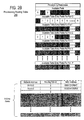
- FIG. 2B is an illustration depicting provisionable routing table for remotely provisioning customers from a single WAN connection in accordance with an exemplary embodiment of the present invention.
- multiple customers are individually provisioned to a single WAN connection utilizing a provisionable router rather than providing a plurality of separate connections to individual customers. Provisioning is accomplished by an ISP service provider remotely updating provisioning preferences in the provisionable router.
- a provisionable router such as routers 110 and 112 shown in FIG. 1 , has a WAN-side port, Port 0 and at least one but more likely a plurality of LAN-side ports, Ports 1 to P.
- routing table 250 note all ports, Ports 0 to P, are available for routing data.
- Port 0 is ported to the WAN or Internet so it is always active and Port 0 hop information is allowed to populate the entry fields in the routing table as determined by the routing protocol (routing protocols use a utility such as PING which causes all network devices reachable on a particular port to respond with their IP addresses).
- Ports 1 to P are reserved for the LAN connections and are provisioned based in provisioning preferences remotely transmitted to the router by the ISP.
- Routing table 250 has a maximum of N possible entry fields for storing hop information. In prior art dynamic routing tables all available entry fields were populated using a routing protocol. In accordance with the present invention, however, hop information from the routing protocol is filtered by provisioning preferences prior to entry in the routing table.
- the present invention limits access to the WAN from a LAN in one of two ways. First, by limiting the number of ports that are active, and second, by limiting the number of entry fields in router table which are active for a particular port.
- An ISP defines active ports and entry fields by setting provisioning preferences. In the depicted figure, note that of the available LAN ports, only Port 2 is not shaded and thus is active. Note also, of the available table entry fields for Port 2, only entries 0, 1 and 2 are not shaded and thus are active and available for hop information.
- the port and entry field preferences are provisioned from a remotely location by the ISP provider by temporarily using the using the customers media connection and bandwidth.
- a router cannot automatically enter hop information in its routing table. Instead, the router must first check the provisioning preferences to determine if the hop information from the routing protocol involves an active port and if so, if an open entry field exists associated with the entry port for the hop information. In the depicted example, only Port 2 is active. Note also that no matter how many networks are connected to Port 2, provisionable routing table 250 has only three active entry fields for the hop information. Therefore, if a customer were to connect multiple nodes to a single port of router 110 for instance, only three networks would be recognized on Port 2. Additionally, provisionable routing table 250 is used for routing protocol requests from other routers, thus other routers cannot identify hops to networks that are a part of the hop information in the routing table.
- provisionable routing table 250 may also contain a MAC address column for each individual machine connected to an active port. In that case, the router performs a MAC or data link layer function normally preformed by a network switch. MAC addresses are populated into the routing table using a modified ARP (address resolution protocol) function.
- ARP address resolution protocol
- a router ARP's a destination node with a device's IP address and the device returns its MAC address.
- the devices on a LAN in the present network may or may not have an IP address so the provisionable router ARP's all devices reachable on an active port for their MAC addresses.
- MAC addresses are then entered no the routing table based on active entry fields.
- the provisionable router opens each packet header and retrieves the destination IP (or network address) as in the prior art, but in accordance with the present invention, also checks the MAC address of the final destination device against the routing table.
- Packets that are sent to a node such as a network switch cannot pass though the provisionable router to the switch's address is listed in the provisionable routing table, the final destination device MAC address must also be entered in the table.
- the provisionable router may also intercept and respond to ARPs from other routers, based on the active MAC addresses in the routing table.
- the customer is limited by the number of MAC address entry fields in the routing table that are activated.
- the ISP has provision one port, Port 2, and three MAC address which may come from up to tree different LAN addresses. Therefore, again with respect to routing table 250 , only three final destination MAC addresses would be recognized by a provisioning router using routing table. In that case, regardless of the number of individual networks, machines or IP addresses for the individual networks and machines, only three MAC addresses would be recognized.
- routing table 250 is a dynamic routing table, that is, although the number of entry fields are limited by the service provider defined provisioning preferences, the value of each active entry (the identity of the network or MAC) is defined by the routing protocol. So while the service provide may limit the total number of entries or network devices listed on the routing table, the service provider does not constrain or define the physical devices to be supported by routing table 250 .
- the routing table is a static routing table. That is, each entry field in the routing table must be entered, usually manually, but certain network devices have the ability to enter their addresses on a static routing table without the use for sophisticated routing protocols.
- FIG. 3 is a flowchart depicting a process for packet handling by a provisionable router in accordance with an exemplary embodiment of the present invention.
- the process begins with the router receiving a data packet (step 302 ) and the router examines the data packet for the packet header (step 304 ). The router then accesses the network address contained in the data packet, the network address identifies a destination, not necessarily the final destination, for the datagram (step 306 ). The router then determines whether the IP address contained in the network address is the provisionable router's own address or some other address (step 308 ). If it is determined that the IP address contained in the packet header is some address other than the router's, the router then accesses its provisioning routing table (step 310 ).
- the provisionable router accesses the information stored in the data packet (step 314 ).
- the router may receive two different types of information: routing information from connected routers and devices based on a routing protocol; or in accordance to an exemplary embodiment of the present invention, the datagram may also contain proprietary provisioning preference information. Therefore, the provisionable router must determine which type of packet it has received (step 316 ). If the router has not received new provisioning preference information, then the information must be routing, or hop, information from other routers and network devices. The router accesses the information in the datagram and updates the hop information in the routing table with information provided to the provisionable router by the data packet (step 318 ). The process then ends.
- the new provisioning preference information must be decrypted prior to utilizing the provisioning data (step 320 ). Then, based on the new provisioning data, the router reconfigures the routing table (step 322 ). Reconfiguring the routing table involves activating and deactivating ports and/or table entry fields for network and MAC addresses. Once the provisioning preferences in the routing table have been reconfigured, the process ends.
- the present invention is described above in terms of limiting access, or connections, to a single media such as a WAN or Internet. Provisioning is accomplished remotely, by utilizing the customer's media connection. The service provider temporarily expropriates media bandwidth for this purpose. However, the present invention is not limited to practice on a single media network device. Other devices that provided customers with multiple media connections are known. Immediately below is a description of system which makes use of one such device.
- FIG. 4 is a diagram that sets forth an exemplary embodiment of FTTH (fiber to the home) system in which the present invention may be implemented.
- Exemplary preferred multimedia services provided via system 400 are plain old telephone service (POTS), high-speed data and video. All three services are combined and distributed from central location 412 , assumed herein to be a central office (CO), and transmitted to customers over fiber optic network 414.
- Resulting outside plant (OSP) 444, 446, 448 preferably contains no active components and thus is referred to as a passive optical network (PON).
- Passive optical splitter 446 terminates single fiber 444 in the distribution plant and feeds up to four customers.
- FTTH system 400 is optimized for low initial first cost. Service costs are deferred until there is demand on a per customer basis. The initial first cost is driven by low OSP cost to place only the fiber cable in the network; either aerial or buried, with no intermediate cross connects. Once a customer requests service, drop fiber 448 is delivered to the individual home via splice 446 off of primary fiber cable 444.
- CLE customer located equipment
- a single, locally powered CLE HNU (home network unit) 450 provides voice, video and data services from fiber 448 entering the home.
- CLE HNU home network unit
- the high bandwidth of the fiber network combined with the simplicity of CLE deployment allows for an increase (scalability) in CLE feature sets and accommodation of new services without requiring additional construction. This scalability advantage of the present invention is not possible with presently implemented access loop networks.
- Central office equipment 412 preferably utilizes a Marconi® MX NGDLC (Next Generation Digital Loop Carrier) product (available from Marconi Communications, Irving, Texas) that provides network distribution, connectivity and control of broadband video and data plus telephony functionality, including a Telecordia certified GR-303 switch interface. Included with the NGDLC product is a unique Optical Mainframe for fiber management, optical multiplexing, and termination as well as an optical video distribution subsystem 438, 434, 430 .
- the FTTH system 400 c an be deployed as an overlay in areas where there is a demand for voice, video and data services, as an alternative method for outside plant rehab, overlay, or in greenfield construction.
- HNU 450 is the CLE unit. HNU 450 is attached to fiber OSP 448 and provides voice, video and data services distributed by the DISC*S® MX Distribution shelf (MDS) 420 at the CO.
- MDS MX Distribution shelf
- HNU 450 preferably receives local power from an external power supply and an optional battery backup supply; (2) The DISC*S® NGDLC configured with the MX Distribution shelf (MDS) that supplies voice/video/data distribution cards that interface with the fiber OSP and with the upstream network switching elements; (3) The SWX Optical Mainframe 430 , which provides management of the distribution fibers from the HNUs, mass fusion splicing for termination into optical distribution equipment and wave division multiplexing; (4) The optical video distribution 438 consisting of fiber amplifiers and transmitters for broadcast of DBS 442 and CATV video 440 ; (5) The broadband data aggregation equipment for transferring packet data to the ISP traffic transmission backbone 426 ; and (6) element management systems (EMSs) 420 to provide operational control of the above items as required or appropriate.
- MDS MX Distribution shelf
- EMSs element management systems
- the OSP is optimized for aerial construction, although the architecture is applicable to buried construction as well.
- the OSP is constructed of fiber cables 444 extending from a central or remote switching location throughout the service area. Each fiber provides service preferably to four homes. The signals on the fibers are transmitted for distances up to 33 kft, without amplification, before termination at passive splitter 446.
- the 4:1 splitter terminates fiber 448 in close proximity (3.3 kft or less) to four homes or living units. Single fiber drop 448 extends from the splitter 446 to each of the living units and terminates at the HNU 450.
- Four way splitters 446 , fiber drops 448, termination of the fiber drop and installation of the HNU 450 are added.to the system as service is required.
- HNU Home Network Unit
- HNU 450 is located inside customer premise 416 and provides the following services: (i) 3 POTS lines 456; (ii) 1 CATV drop (50-750MHz) 460; (iii) 1 DBS drop (950-2050MHz) 458; and (iv) 1 10Mbps Ethernet drop 454. HNU 450 is locally powered via an external power supply co-located inside customer premise 416. Lifeline POTS is supported by optional battery backup on a single POTS line. The battery backup consists of a unit external to HNU 450 that accepts commonly available "C" cell or 9 volt batteries.
- the HNU 50 is preferably mounted on a wall inside the living unit.
- the HNU housing is preferably a "clam shell” box with a hinged cover providing access to the circuit board and fiber loop inside the unit.
- a lock is provided to prevent unauthorized entry to the HNU.
- Fiber drop cable 448 enters HNU 450 housing.
- the mechanical termination of fiber cable 448 and optional strength member is provided as an integral part of HNU 450 housing.
- Fiber drop 448 termination is provided jointly by HNU 450 unit mechanics and HNU 450 circuit board.
- HNU 450 hinged cover contains an integrated fusion splice tray where the fiber drop to the home is spliced into the HNU internal fiber loop. The HNU internal fiber loop is then terminated on the HNU circuit board.
- HNU 450 provides all services on a single circuit card mounted in the housing.
- the HNU circuit board provides the WDM and electrical to optical conversion functions to extract the POTS and data signals from the 1310nm wavelength and the video signals from the 1550nm wavelength.
- HNU 450 converts the electrical signals to optical signals and multiplexes the 1330nm and 1550nm wavelengths onto the fiber for transport back to the CO.
- the POTS, video and Ethernet data are provided as connectorized outputs on the HNU 450 housing.
- Three RJ11 connectors are provided for connection to the house telephone wiring. Each connector provides a separate, private line. Two 'F' type connectors are provided for video feeds into the customer premise. One connector provides the CATV signal and the other provides the digital DBS signal.
- a single RJ45 connector is provided for a 10Base "_" T high-speed data connection to the customer's computer.
- HNU 450 Voice traffic is received and transmitted in a packetized format by HNU 450.
- HNU 450 provides the battery (optional external), ringing, supervision (off-hook/on-hook), and PCM coding of telephony BORSCHT functions for each POTS line.
- the resulting POTS line interfaces at the three RJ11 jacks on HNU 450 meet the requirements of TR-57, as applicable.
- the POTS line interfaces are also compatible with implementation of CLASS services.
- Video signal 460 reception range is from 50 to 2050 MHz.
- the DBS signal 458 reception is 950-2050MHz. Standard DBS set top boxes will be used to decode the signals.
- CATV signal reception is 50-750MHz.
- the HNU CATV interface (coax 'F' connector) complies with NTSC standards and provides 25 analog channels and 140 digitally-modulated channels of programming.
- the HNU DBS interface (coax F connector) complies with the Hughes DBS standard for the provision of a full range of DBS channels.
- HNU data traffic is received and transmitted as Ethernet packets using Point-to-Point Protocol over Ethernet (PPPoE).
- PPPoE Point-to-Point Protocol over Ethernet
- the 10Base "_" T interface provided at HNU 450 is IEEE 802.3 compliant.
- the HNU 10Base-T interface is connected to a standard Network Interface Card (NIC) installed in the customer's computer over CAT-3 or CAT-5 cabling in the home.
- NIC Network Interface Card
- the PPPoE session is initiated at the customer's computer and terminated by the ISP provider.
- the high-speed data service downstream performance is 20Mbps shared among four homes connected at Passive Optical Splitter 446 with downstream burst capability of 10Mbps to each home.
- the upstream performance is 4.5Mbps dedicated for each home. All four of the homes linked to Passive Optical Splitter 446 have the ability to conduct simultaneous 4.5Mbps data sessions.
- HNU 450 executes power shedding during an AC power outage to automatically shut down video and data services to conserve battery power.
- An exemplary CO consists of Splitter WDM Frame (SWX) 430, fiber amplifiers and transmitters 438 , high power optical amplifier (FOA) 434, and voice and data distribution center 420.
- the Splitter WDM Frame (SWX) 430 assembly collects the feeder network fibers from the HNUs 450 via the CO cable vault.
- the SWX shelf 430 subassembly is a passive optical signal distribution system that provides mass fusion termination of up to 96 of these fibers to fiber jumpers routed to the DISC*S® MX MDS 20F shelf.
- the SWX 430 also performs the WDM function to separate the 1310nm signals (voice/data) from the 1550nm signals (video) onto separate fibers within the CO.
- a single fiber carrying 1550nm video signals is routed to the Optical Video Distribution equipment 438. Fibers carrying 1310nm voice/data signals from all the HNUs 50 (4 per fiber) are routed to voice and data distribution center 420.
- SWX 430 also provides multiplexing of a 1550nm video broadcast signal from a single fiber to 32 outgoing fibers.
- the CATV and DBS signals 440, 442 entering the CO from the service provider head-end and satellite are received at the E/O 438, which combines both signals into a 1550nm signal carried over a single fiber.
- This combined optical video signal is then amplified by a high power optical amplifier (FOA) 438 that acts as the "booster" stage in the CO Optical Video Distribution subsystem.
- the output of the booster FOA is fed to an optical splitter (not shown) that fans out the combined optical video signal to multiple parallel FOAs that act as the distribution amplifier stages.
- the number of distribution FOAs is a function of the number of fibers in the network.
- the output of the distribution FOA is routed over fiber to an SWX(s) 430.
- An example of an FOA is an Erbium-Doped Fiber Amplifier (EDFA), although other types of optical amplifiers could be used with the invention.
- EDFA Erbium-Doped Fiber Amplifier
- the fibers carrying voice and data signals over 1310nm are routed from SWX 430 to a MX MDS shelf contained in voice and data distribution center 420.
- the fibers are connected directly to the QOIU81 (Quad Optical Interface Unit) cards 420A in the MDS shelf.
- QOIU81 Quad Optical Interface Unit
- Each QOIU81 in voice and data distribution center 420 accepts four fibers, where each fiber is carrying voice and data for four of HNUs 450.
- a QOIU81 card performs the optical to electrical conversion for four optical signals.
- the voice data is removed from the data stream received from HNU 450 and routed to a structured DS-0 TDM bus on the MDS backplane.
- the TDM data is passed to a DPU1 (Data Processing Unit) where the TSI function local to the MDS backplane is performed.
- the TDM voice data is then passed to the DISC*S® Common shelf co-located in the same frame as the MDS shelf.
- the DISC*S® Common Shelf performs call processing and provides a TR-008 or GR-303 interface to the voice switch.
- the Common Shelf implements a non-blocking 672 x 672 channel Time Slot Interchanger.
- the Common Shelf implementation of GR-303 is fully compliant to Telcordia requirements and has been certified with all the major switch vendors' equipment.
- the GR-303 implementation includes flexible concentration.
- the Common Shelf further includes a Fuse and Alarm Panel that monitors the MDS shelf as well as the Common Shelf elements.
- the Fuse and Alarm Panel includes 16 alarm contacts that can be used to monitor other equipment, such as the Optical Video Distribution equipment.
- the 1310nm optical signals 428 received by the QOIU81 cards in the MDS shelf also include Ethernet data packets from HNUs 450.
- the QOIU81 removes the data packets from the digital signals derived from optical to electrical conversion of the signals received from all four fibers terminated at the card.
- the QOIU81 multiplexes the Ethernet data packets onto a single 100Base "_" T output.
- the 100Base "_” T output carries data traffic from 16 homes consisting of up to 4 PPPoE sessions each.
- the 100Base "_” T signal from each QOIU81 is connected to an external Data Aggregation device over CAT-5 wiring in the CO.
- the Data Aggregation device(s) aggregates the Ethernet traffic from the QOIU81s in voice and data distribution center 420.
- the output of the Data Aggregation device is connected to the telephony service provider's Data Transmission Backbone 426 .
- HNU 500 contains WDM O/E 510 (wave division multiplexer optical to electrical) that functions identically to WDM O/E 452 discussed above with respect to FIG. 4.
- WDM O/E 510 wave division multiplexer optical to electrical
- the optical signal is converted into a plurality of separate electrical signals for desperate media devices.
- These signals include up to three POTS 556 lines shown as lines 1, 2, and 3 for telephony services; DBS 558 for providing direct broadcast video services as discussed above; CATV 560 for providing cable video media services; and data channel 554 for providing 10BaseT.
- POTS 556 lines shown as lines 1, 2, and 3 for telephony services
- DBS 558 for providing direct broadcast video services as discussed above
- CATV 560 for providing cable video media services
- data channel 554 for providing 10BaseT.
- HNU 450 shown in FIG.
- HNU 500 includes a provisionable data router and several media switches for provisioning media services to the customer.
- Provisionable data router 520 is actually a routing circuit or chip with embedded routing functionality, however, provisionable router 520 functions in a similar manner to process depicted above with respect to FIG. 3.
- the HNU of the present invention allows for additional data ports to provide additional data signal connections to the customer. These are shown by the dashed lines coming from router 520 and depicted as data 554.
- Data router 520 is also ported to HNU processor 502 .
- HNU processor 502 contains encryption/decryption functions 504 and control and status functions 506 and is further connected to sufficient RAM 508 to execute the onboard functionality.
- HNU processor 502 controls provisioning and status functionality of HNU 500 from control information sent via the Internet to HNU 500.
- the control information include both provisioning and status requests from the service provider.
- Data router 520 routes customer packets to one of data 554 and provisioning and status request packets to HNU processor 502 .
- HNU 502 decrypts packets using encryption/decryption functions 504 and then control and status functionality 506 executes the requested operation.
- Provisioning is accomplished by activating or deactivating any one of a plurality of media switched contained within HNU 500 .
- these media switches are in the normally-off switches or contain normally-off switching logic as a base state.
- These media switches include CATV switch 530, DBS switch 532, and POTs switch 534, 536 and 538 for controlling POTs lines.
- Data router 520 routes data to one of three data ports, data 554 and provides the means for provisioning, monitoring or troubleshooting and collecting performance data.
- HNU 500's provisioning, monitoring, troubleshooting and performance collection capabilities are accessed using a web browser via an HTTP or similar protocol web page at the CO.
- HNU 500 may also autonomously provide the service provider with status reports by using control and status functions 506.
- HNU processor 502 accumulates status information, encrypts the status information using encryption/decryption functions 504, addresses a data packet containing the status function to the service provider and router 520 transmits the status information to the CO using any connected WAN (of course, here it is expected the WAN is the Internet). This feature greatly improves service quality for the service provider, especially involving customers with very little or no technical expertise.
- the helper can merely access the status log for the customer's particular HNU for a basis to begin the troubleshooting. Additionally, the help representative can initiate status requests from the HNU and initiate on-board trouble-shooting and diagnostics for evaluating the customer's problem with a web browser.
- a flowchart depicting packet handling by a remote provisioning HNU is illustrated in accordance with an exemplary embodiment of the present invention.
- the process begins with the HNU receiving a data packet (step 602 ).
- the WDM O/E has converted the optical information to electrical information and the data is actually being received in the data router.
- the router then examines the data packet header (step 604 ) and accesses the network address contained within the packet header (step 606 ).
- the router determines whether the IP address contained in the header defines the HNU (step 608 ). If not, it is assumed that the packet is to be routed to one of the data ports on the HNU.
- the router determine whether the network address is listed on the routing table (step 609 ).
- the router identifies the data port associated with the network (step 610 ). The router then transmits the packet to the target networks over the identified port (step 612 ). The process then ends with respect to routing a customer data packet.
- the router accesses the datagram (step 614 ). Depending on the type of request information contained in the datagram, the data router either processes the request internally or passes the information to the HNU processor for processing. Thus, a series of checks are made on the data packet to identify the type of request being received at the data router. The first check is to determine if the packet contains a status request (step 616 ). If so, the packet is passed to the HNU processor which decrypts the request information (step 618 ). The HNU processor then calls for switch and router state information from the various onboard components of the HNU (step 620 ).
- the processor Having received the switch and state information, the processor then compiles and encrypts a status report which is passed to the router (step 622 ). Finally, the router returns the encrypted switch and router state information to the requestor based on the source IP address contained in the header of the request packet (step 624 ). The process then ends.
- step 616 if the information in the data packet cannot be identified as a status request, a check is made to determine if the information contains a router provisioning request (step 626 ). If so, the router provisioning information is decrypted (step 628 ).
- the router may, itself, contain onboard encryption/decrypting functionality or more likely rely on the HNU processor for decryption functions. In the latter case, once the router identifies the packet as containing a provisioning request, the packet's contents are sent to the HNU processor for decryption and the decrypted request returned to the data router for processing. Regardless of which element decrypts the packet, the data router reconfigures the routing table based on the provisioning preference information contained in the provisioning request (step 630 ). The process then ends.
- step 632 a check is made to determine if the data packet contains a media switch provisioning request.
- data router 520 provisions media data 555 while a plurality of media switches 530-538 provision other media types with respect to HNU 500. Therefore, if it is determined in step 632 that the data packet contains a switch provisioning request, the packet is then transferred to the HNU processor which decrypts the switch-provisioning request (step 634 ). The HNU processor then resets the switch(es) based on the provisioning request (step 636 ). The process then ends with respect to the switch-provisioning request.
- the data packet if the data packet does not contain either a status request, a router-provisioning request, or a switch provisioning request, then the packet must contain routing information from routing protocol for configuring hops between nodes. In that case, the data router updates the routing table entry based on the hop information in the routing packet (step 638 ) and the process ends. At this point, any data packet transferred to the HNU via a WAN such as the Internet has been processed.
- the Ethernet frame layout specified by the DIX (DEC-Intel-Xerox) standard contains a type field, as can be seen in Table II below.
- the type field contains a type number that describes the type of high-level network protocol (such as TCP/IP) being carried by the Ethernet frame.
- TCP/IP high-level network protocol
- the type field was replaced by a more general, but more complex, set of frame specifiers. Nevertheless, many network software implementations still use the DIX frame specification, and its Ethernet type field.
- IEEE Registration Authority IEEE Standards Department 445 Hoes Lane, P.O. Box 1331 Piscataway NJ 08844-1331.
- data packets are routed (switched is the more accurate term for a MAC level routing operation) by network type as designated in the "Ethernet Type" packet field.
- Ethernet II Frame Layout 8 Bytes Preamble 6 Bytes Destination MAC Address 6 Bytes Source MAC Address 2 Bytes Ethernet Type 46-1500 Bytes Data 6 Bytes Destination MAC Address 2 Bytes CRC/FCS
- the HNU may contain a network data switch rather than a data router for processing provisioning in status requests and for provisioning media data from the HNU.
- FIG. 7 is a diagram depicting an HNU utilizing an addressable network switch for processing provisioning and status requests in accordance with an exemplary embodiment of the present invention.
- HNU 700 contains WDM O/E 710 for converting the optical signal to a plurality of electrical media signals based on the bandwidth contained within the optical signal. Each media signal is then routed through a media switch. For instance, data switch 720 , CATV 730, DBS switch 732, POTS switch 734, POTS switch 736 and POTS switch 738 .
- Each of the data switches is connected to HNU processor 702 via a data bus in a similar fashion as HNU 500 shown in FIG. 5.
- the present embodiment utilizes network data switch 720 for switching data packets based on the packet's Ethernet type designation.
- a packet wrapped in a packet designated as an Ethernet type that is designated for the HNU is passed to HNU processor 702 .
- data switch 702 switches data packets wrapped in a client's Ethernet type to data port 754 . Therefore, in this embodiment HNU 700 receives provisioning and status requests off the Internet similar to that described with respect to HNU 500 shown in FIG.
- HNU 700 may utilize a single IP address for all data packets as opposed to HNU 500, FIG. 5, in which HNU 500 is expected to have one IP address and each of the data ports serviced by data router 520 may also maintains a separate IP address.
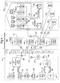
- FIG. 8 a flowchart depicts a process for processing data packets in an HNU in accordance with an exemplary embodiment of the present invention.
- the process begins with the HNU receiving a data packet (step 802 ).
- the data packet is directed to the data switch by the ODM O/E where the switch examines the data packet Ethernet wrapper (step 804 ).
- packets of data are layered or wrapped in protocol layers or stacks. Once a packet is received by a device, it is unwrapped or the stack is popped in reverse order that it was loaded. At this point in the process, the packet has already been identified by its IP address as belonging or being addressed to the HNU and transferred to the data switch.
- the data switch After examining the data packet's Ethernet wrapper, the data switch accesses the datagram header for the Ethernet types (step 806 ). This header identifies the Ethernet type protocol for handling the packet wrapped within. A decision is then made by the data switch as to whether the Ethernet type specified in the packet header is that of the HNU (step 808 ). If it is determined not to be the HNU's Ethernet type, the data packet is passed to the data port for customer use (step 810 ). At this point, the process ends with regard to the HNU processing data packets destined for customer use.
- the switch passes the datagram to the HNU processor which then accesses the datagram (step 814 ).
- the HNU processor then must determine whether the datagram contains a status request or switch provision data. Thus, a check is made to determine whether the datagram contains a status request (step 816 ). If the datagram contains a status request the HNU processor decrypts the datagram (step 818 ), and calls each switch for state information (step 820 ). Having received the state information from each switch in the HNU, the HNU processor then encrypts the switch state data (step 822 ), and returns the encrypted switch data to the requestor via the data switch. The process for handling status request packet is then complete.
- the HNU processor decrypts the switch provisioning request (step 834 ) and utilizing the on-board data bus, resets media switches based on the switch-provisioning request (step 836 ). The process then ends with respect to provisioning media switches.
Abstract
Description
| | Protocol | |
| 1 | RS-232 V.35 SONET | |
| 1-2 | 802.11 wireless | |
| 2 | Ethernet Fast Ethernet Gigabit Ethernet Token Ring FDDI | |
| 3 | IP (TCP/IP) IPX (NetWare) | |
| 4 | SPX (NetWare) TCP (TCP/IP) UDP (TCP/IP) NetBEUI (NetBIOS) | |
| 5 | | |
| 6 | ASN.1 | |
| 7 | SMB (NetBEUI) AFP (AppleTalk) NCP (NetWare) NFS (TCP/IP) HTTP (TCP/IP) FTP (TCP/IP) SMTP (TCP/IP) DNS (TCP/IP) |
| (Ethernet II Frame Layout) | ||||||
| 8 | 6 Bytes | 6 Bytes | 2 Bytes Ethernet Type | 46-1500 | 6 Bytes | 2 Bytes CRC/FCS |
Claims (17)
- A method for provisioning a media service using customer located equipment comprising:receiving a signal on customer allocated media in a customer located device;identifying the signal as either a customer destined signal or a device destined signal; andprovisioning at least one media based on the signal being identified as a device destined signal.
- The method of claim 1, wherein the customer allocated media is one of a WAN (wide are network), LAN (local are network) or Internet.
- The method of claim 1, wherein provisioning at least one media based on the signal being identified as a device destined signal further comprises:ascertaining a media type to be provisioned from information contained in the data packet; andresetting a switch, wherein the switch controls output of the ascertained media.
- The method of claim 1, wherein identifying the signal as either a customer destined signal or a device destined signal further comprises:determining an Ethernet type from information contained in the signal; andclassifying the Ethernet type as being one of a device Ethernet type and a customer Ethernet type.
- The method of claim 4, wherein provisioning at least one media based on the signal being identified as a device destined is based on the signal being of the device Ethernet type.
- The method of claim 1, wherein the device is one of a network switch, a router and an optical/electrical interface.
- The method of claim 1, wherein the at least one media is one of data, video and telephony.
- The method of claim 1, further comprises:accumulated state information pertaining to the customer located device; andtransmitting the state information on customer allocated media to a remote location.
- A method for monitoring customer located equipment comprising:receiving a signal on customer allocated media in a customer located device;identifying the signal as either a customer destined signal or a device destined signal;responding to the signal based on the signal being identified as a device destined signal, wherein the response includes state information pertaining to the device.
- The method of claim 1, wherein subsequent to identifying the signal as a device destined signal the method further comprises:polling at least one component of the device for state information.
- A customer located device for provisioning a media service comprising:a first port, wherein the first port is capable of receiving media;a second port, wherein the second port is capable of transmitting media;a media switch connected between the first port and second port; anda media switch controller connected between the first port and the switch.
- The device of claim 11, wherein the device is one of a network switch, a router and an optical/electrical media interface unit.
- The device of claim 11, wherein the media switch is a first media switch, the device further comprising:a third port, wherein the third port is capable of transmitting media;a second media switch connected between the first port and the third port and is further connected between the media controller and the third port.
- The device of claim 11, wherein the first port is connect to one of a WAN (wide are network) and an Internet.
- The device of claim 11, further comprises:an optical/electrical interface connected between the first port and the first media switch.
- The device of claim 11, wherein the media service is one of data, video and telephony.
- The device of claim 11, further comprises:a processor; andRAM (random access memory).
Applications Claiming Priority (2)
| Application Number | Priority Date | Filing Date | Title |
|---|---|---|---|
| US70306900A | 2000-10-31 | 2000-10-31 | |
| US703069 | 2000-10-31 |
Publications (2)
| Publication Number | Publication Date |
|---|---|
| EP1202494A2 true EP1202494A2 (en) | 2002-05-02 |
| EP1202494A3 EP1202494A3 (en) | 2004-01-02 |
Family
ID=24823849
Family Applications (1)
| Application Number | Title | Priority Date | Filing Date |
|---|---|---|---|
| EP01125899A Withdrawn EP1202494A3 (en) | 2000-10-31 | 2001-10-30 | Method and system for remotely maintaining and provisioning equipment over a wide area network |
Country Status (1)
| Country | Link |
|---|---|
| EP (1) | EP1202494A3 (en) |
Cited By (10)
| Publication number | Priority date | Publication date | Assignee | Title |
|---|---|---|---|---|
| EP1502385A1 (en) * | 2002-05-09 | 2005-02-02 | Optical Solutions, Inc. | Network address assignment in a passive optical network |
| EP1528748A1 (en) * | 2003-10-27 | 2005-05-04 | Marconi Intellectual Property (Ringfence) Inc. | Method and system for managing computer networks |
| DE10357416A1 (en) * | 2003-12-03 | 2005-07-14 | Siemens Ag | Arrangement for connecting an optical waveguide with a microprocessor-controlled electrical device |
| WO2005064851A1 (en) * | 2003-12-30 | 2005-07-14 | Bce Inc. | Remotely managed subscriber station |
| AU2011101297B4 (en) * | 2011-08-15 | 2012-06-14 | Uniloc Usa, Inc. | Remote recognition of an association between remote devices |
| US8452960B2 (en) | 2009-06-23 | 2013-05-28 | Netauthority, Inc. | System and method for content delivery |
| US8736462B2 (en) | 2009-06-23 | 2014-05-27 | Uniloc Luxembourg, S.A. | System and method for traffic information delivery |
| US8812701B2 (en) | 2008-05-21 | 2014-08-19 | Uniloc Luxembourg, S.A. | Device and method for secured communication |
| US8903653B2 (en) | 2009-06-23 | 2014-12-02 | Uniloc Luxembourg S.A. | System and method for locating network nodes |
| US10572867B2 (en) | 2012-02-21 | 2020-02-25 | Uniloc 2017 Llc | Renewable resource distribution management system |
Citations (3)
| Publication number | Priority date | Publication date | Assignee | Title |
|---|---|---|---|---|
| US5636211A (en) * | 1995-08-15 | 1997-06-03 | Motorola, Inc. | Universal multimedia access device |
| US5881131A (en) * | 1993-11-16 | 1999-03-09 | Bell Atlantic Network Services, Inc. | Analysis and validation system for provisioning network related facilities |
| WO1999053654A1 (en) * | 1998-04-16 | 1999-10-21 | Ameritech | Home gateway system and method |
-
2001
- 2001-10-30 EP EP01125899A patent/EP1202494A3/en not_active Withdrawn
Patent Citations (3)
| Publication number | Priority date | Publication date | Assignee | Title |
|---|---|---|---|---|
| US5881131A (en) * | 1993-11-16 | 1999-03-09 | Bell Atlantic Network Services, Inc. | Analysis and validation system for provisioning network related facilities |
| US5636211A (en) * | 1995-08-15 | 1997-06-03 | Motorola, Inc. | Universal multimedia access device |
| WO1999053654A1 (en) * | 1998-04-16 | 1999-10-21 | Ameritech | Home gateway system and method |
Cited By (16)
| Publication number | Priority date | Publication date | Assignee | Title |
|---|---|---|---|---|
| EP1502385A1 (en) * | 2002-05-09 | 2005-02-02 | Optical Solutions, Inc. | Network address assignment in a passive optical network |
| EP1502385A4 (en) * | 2002-05-09 | 2005-11-02 | Optical Solutions Inc | Network address assignment in a passive optical network |
| US7020157B2 (en) | 2002-05-09 | 2006-03-28 | Optical Solutions, Inc. | Network address assignment in a passive optical network |
| US7525980B2 (en) | 2002-05-09 | 2009-04-28 | Calix Networks, Inc. | Network address assignment in a passive optical network |
| US7613195B2 (en) | 2003-10-27 | 2009-11-03 | Telefonaktiebolaget L M Ericsson (Publ) | Method and system for managing computer networks |
| EP1528748A1 (en) * | 2003-10-27 | 2005-05-04 | Marconi Intellectual Property (Ringfence) Inc. | Method and system for managing computer networks |
| DE10357416A1 (en) * | 2003-12-03 | 2005-07-14 | Siemens Ag | Arrangement for connecting an optical waveguide with a microprocessor-controlled electrical device |
| US8804569B2 (en) | 2003-12-30 | 2014-08-12 | Bce Inc. | Management session initiation with a customer premises device |
| WO2005064851A1 (en) * | 2003-12-30 | 2005-07-14 | Bce Inc. | Remotely managed subscriber station |
| US8812701B2 (en) | 2008-05-21 | 2014-08-19 | Uniloc Luxembourg, S.A. | Device and method for secured communication |
| US8452960B2 (en) | 2009-06-23 | 2013-05-28 | Netauthority, Inc. | System and method for content delivery |
| US8736462B2 (en) | 2009-06-23 | 2014-05-27 | Uniloc Luxembourg, S.A. | System and method for traffic information delivery |
| US8903653B2 (en) | 2009-06-23 | 2014-12-02 | Uniloc Luxembourg S.A. | System and method for locating network nodes |
| AU2011101297B4 (en) * | 2011-08-15 | 2012-06-14 | Uniloc Usa, Inc. | Remote recognition of an association between remote devices |
| US8693473B2 (en) | 2011-08-15 | 2014-04-08 | Uniloc Luxembourg, S.A. | Remote recognition of an association between remote devices |
| US10572867B2 (en) | 2012-02-21 | 2020-02-25 | Uniloc 2017 Llc | Renewable resource distribution management system |
Also Published As
| Publication number | Publication date |
|---|---|
| EP1202494A3 (en) | 2004-01-02 |
Similar Documents
| Publication | Publication Date | Title |
|---|---|---|
| US7272137B2 (en) | Data stream filtering apparatus and method | |
| US10103982B2 (en) | System and method for automatic routing of dynamic host configuration protocol (DHCP) traffic | |
| US6850495B1 (en) | Methods, apparatus and data structures for segmenting customers using at least a portion of a layer 2 address header or bits in the place of a layer 2 address header | |
| US6771673B1 (en) | Methods and apparatus and data structures for providing access to an edge router of a network | |
| US8127029B1 (en) | Internet protocol based network architecture for cable television network access with switched fallback | |
| US6993026B1 (en) | Methods, apparatus and data structures for preserving address and service level information in a virtual private network | |
| US9853896B2 (en) | Method, device, and virtual private network system for advertising routing information | |
| US7489700B2 (en) | Virtual access router | |
| US6452925B1 (en) | Universal access multimedia data network | |
| US8125915B2 (en) | Remote management of a bridge device | |
| US8611363B2 (en) | Logical port system and method | |
| US8402120B1 (en) | System and method for locating and configuring network device | |
| JP5295273B2 (en) | Data stream filtering apparatus and method | |
| MXPA05012873A (en) | Method for exchanging packets of user data. | |
| US20070121619A1 (en) | Communications distribution system | |
| EP1202494A2 (en) | Method and system for remotely maintaining and provisioning equipment over a wide area network | |
| KR20020010159A (en) | A device and a method in a switched telecommunication system | |
| US11700228B2 (en) | Hardware address consistency management | |
| US11456988B1 (en) | MAP-T border relay controller | |
| JP6546560B2 (en) | Provider side optical line termination device, multicast transmission method and computer program | |
| Irie et al. | Large capacity multiplex-port brouter for regional PC communication network system | |
| Sequeira | CompTIA Network+ N10-006 Quick Refernce | |
| LE | CHAPTER CMTS Systems |
Legal Events
| Date | Code | Title | Description |
|---|---|---|---|
| PUAI | Public reference made under article 153(3) epc to a published international application that has entered the european phase |
Free format text: ORIGINAL CODE: 0009012 |
|
| AK | Designated contracting states |
Kind code of ref document: A2 Designated state(s): AT BE CH CY DE DK ES FI FR GB GR IE IT LI LU MC NL PT SE TR |
|
| AX | Request for extension of the european patent |
Free format text: AL;LT;LV;MK;RO;SI |
|
| RAP1 | Party data changed (applicant data changed or rights of an application transferred) |
Owner name: MARCONI INTELLECTUAL PROPERTY (RINGFENCE) INC. |
|
| PUAL | Search report despatched |
Free format text: ORIGINAL CODE: 0009013 |
|
| AK | Designated contracting states |
Kind code of ref document: A3 Designated state(s): AT BE CH CY DE DK ES FI FR GB GR IE IT LI LU MC NL PT SE TR |
|
| AX | Request for extension of the european patent |
Extension state: AL LT LV MK RO SI |
|
| AKX | Designation fees paid | ||
| REG | Reference to a national code |
Ref country code: DE Ref legal event code: 8566 |
|
| STAA | Information on the status of an ep patent application or granted ep patent |
Free format text: STATUS: THE APPLICATION IS DEEMED TO BE WITHDRAWN |
|
| 18D | Application deemed to be withdrawn |
Effective date: 20040703 |