EP1202359A2 - Cooling arrangement for power supply apparatus - Google Patents
Cooling arrangement for power supply apparatus Download PDFInfo
- Publication number
- EP1202359A2 EP1202359A2 EP20010125807 EP01125807A EP1202359A2 EP 1202359 A2 EP1202359 A2 EP 1202359A2 EP 20010125807 EP20010125807 EP 20010125807 EP 01125807 A EP01125807 A EP 01125807A EP 1202359 A2 EP1202359 A2 EP 1202359A2
- Authority
- EP
- European Patent Office
- Prior art keywords
- supply apparatus
- power supply
- power modules
- surface plate
- power
- Prior art date
- Legal status (The legal status is an assumption and is not a legal conclusion. Google has not performed a legal analysis and makes no representation as to the accuracy of the status listed.)
- Granted
Links
Images


Classifications
-
- H—ELECTRICITY
- H01—ELECTRIC ELEMENTS
- H01M—PROCESSES OR MEANS, e.g. BATTERIES, FOR THE DIRECT CONVERSION OF CHEMICAL ENERGY INTO ELECTRICAL ENERGY
- H01M10/00—Secondary cells; Manufacture thereof
- H01M10/60—Heating or cooling; Temperature control
- H01M10/61—Types of temperature control
- H01M10/613—Cooling or keeping cold
-
- B—PERFORMING OPERATIONS; TRANSPORTING
- B60—VEHICLES IN GENERAL
- B60K—ARRANGEMENT OR MOUNTING OF PROPULSION UNITS OR OF TRANSMISSIONS IN VEHICLES; ARRANGEMENT OR MOUNTING OF PLURAL DIVERSE PRIME-MOVERS IN VEHICLES; AUXILIARY DRIVES FOR VEHICLES; INSTRUMENTATION OR DASHBOARDS FOR VEHICLES; ARRANGEMENTS IN CONNECTION WITH COOLING, AIR INTAKE, GAS EXHAUST OR FUEL SUPPLY OF PROPULSION UNITS IN VEHICLES
- B60K6/00—Arrangement or mounting of plural diverse prime-movers for mutual or common propulsion, e.g. hybrid propulsion systems comprising electric motors and internal combustion engines ; Control systems therefor, i.e. systems controlling two or more prime movers, or controlling one of these prime movers and any of the transmission, drive or drive units Informative references: mechanical gearings with secondary electric drive F16H3/72; arrangements for handling mechanical energy structurally associated with the dynamo-electric machine H02K7/00; machines comprising structurally interrelated motor and generator parts H02K51/00; dynamo-electric machines not otherwise provided for in H02K see H02K99/00
- B60K6/20—Arrangement or mounting of plural diverse prime-movers for mutual or common propulsion, e.g. hybrid propulsion systems comprising electric motors and internal combustion engines ; Control systems therefor, i.e. systems controlling two or more prime movers, or controlling one of these prime movers and any of the transmission, drive or drive units Informative references: mechanical gearings with secondary electric drive F16H3/72; arrangements for handling mechanical energy structurally associated with the dynamo-electric machine H02K7/00; machines comprising structurally interrelated motor and generator parts H02K51/00; dynamo-electric machines not otherwise provided for in H02K see H02K99/00 the prime-movers consisting of electric motors and internal combustion engines, e.g. HEVs
- B60K6/22—Arrangement or mounting of plural diverse prime-movers for mutual or common propulsion, e.g. hybrid propulsion systems comprising electric motors and internal combustion engines ; Control systems therefor, i.e. systems controlling two or more prime movers, or controlling one of these prime movers and any of the transmission, drive or drive units Informative references: mechanical gearings with secondary electric drive F16H3/72; arrangements for handling mechanical energy structurally associated with the dynamo-electric machine H02K7/00; machines comprising structurally interrelated motor and generator parts H02K51/00; dynamo-electric machines not otherwise provided for in H02K see H02K99/00 the prime-movers consisting of electric motors and internal combustion engines, e.g. HEVs characterised by apparatus, components or means specially adapted for HEVs
- B60K6/28—Arrangement or mounting of plural diverse prime-movers for mutual or common propulsion, e.g. hybrid propulsion systems comprising electric motors and internal combustion engines ; Control systems therefor, i.e. systems controlling two or more prime movers, or controlling one of these prime movers and any of the transmission, drive or drive units Informative references: mechanical gearings with secondary electric drive F16H3/72; arrangements for handling mechanical energy structurally associated with the dynamo-electric machine H02K7/00; machines comprising structurally interrelated motor and generator parts H02K51/00; dynamo-electric machines not otherwise provided for in H02K see H02K99/00 the prime-movers consisting of electric motors and internal combustion engines, e.g. HEVs characterised by apparatus, components or means specially adapted for HEVs characterised by the electric energy storing means, e.g. batteries or capacitors
-
- B—PERFORMING OPERATIONS; TRANSPORTING
- B60—VEHICLES IN GENERAL
- B60K—ARRANGEMENT OR MOUNTING OF PROPULSION UNITS OR OF TRANSMISSIONS IN VEHICLES; ARRANGEMENT OR MOUNTING OF PLURAL DIVERSE PRIME-MOVERS IN VEHICLES; AUXILIARY DRIVES FOR VEHICLES; INSTRUMENTATION OR DASHBOARDS FOR VEHICLES; ARRANGEMENTS IN CONNECTION WITH COOLING, AIR INTAKE, GAS EXHAUST OR FUEL SUPPLY OF PROPULSION UNITS IN VEHICLES
- B60K1/00—Arrangement or mounting of electrical propulsion units
- B60K1/04—Arrangement or mounting of electrical propulsion units of the electric storage means for propulsion
-
- B—PERFORMING OPERATIONS; TRANSPORTING
- B60—VEHICLES IN GENERAL
- B60K—ARRANGEMENT OR MOUNTING OF PROPULSION UNITS OR OF TRANSMISSIONS IN VEHICLES; ARRANGEMENT OR MOUNTING OF PLURAL DIVERSE PRIME-MOVERS IN VEHICLES; AUXILIARY DRIVES FOR VEHICLES; INSTRUMENTATION OR DASHBOARDS FOR VEHICLES; ARRANGEMENTS IN CONNECTION WITH COOLING, AIR INTAKE, GAS EXHAUST OR FUEL SUPPLY OF PROPULSION UNITS IN VEHICLES
- B60K6/00—Arrangement or mounting of plural diverse prime-movers for mutual or common propulsion, e.g. hybrid propulsion systems comprising electric motors and internal combustion engines ; Control systems therefor, i.e. systems controlling two or more prime movers, or controlling one of these prime movers and any of the transmission, drive or drive units Informative references: mechanical gearings with secondary electric drive F16H3/72; arrangements for handling mechanical energy structurally associated with the dynamo-electric machine H02K7/00; machines comprising structurally interrelated motor and generator parts H02K51/00; dynamo-electric machines not otherwise provided for in H02K see H02K99/00
- B60K6/20—Arrangement or mounting of plural diverse prime-movers for mutual or common propulsion, e.g. hybrid propulsion systems comprising electric motors and internal combustion engines ; Control systems therefor, i.e. systems controlling two or more prime movers, or controlling one of these prime movers and any of the transmission, drive or drive units Informative references: mechanical gearings with secondary electric drive F16H3/72; arrangements for handling mechanical energy structurally associated with the dynamo-electric machine H02K7/00; machines comprising structurally interrelated motor and generator parts H02K51/00; dynamo-electric machines not otherwise provided for in H02K see H02K99/00 the prime-movers consisting of electric motors and internal combustion engines, e.g. HEVs
- B60K6/22—Arrangement or mounting of plural diverse prime-movers for mutual or common propulsion, e.g. hybrid propulsion systems comprising electric motors and internal combustion engines ; Control systems therefor, i.e. systems controlling two or more prime movers, or controlling one of these prime movers and any of the transmission, drive or drive units Informative references: mechanical gearings with secondary electric drive F16H3/72; arrangements for handling mechanical energy structurally associated with the dynamo-electric machine H02K7/00; machines comprising structurally interrelated motor and generator parts H02K51/00; dynamo-electric machines not otherwise provided for in H02K see H02K99/00 the prime-movers consisting of electric motors and internal combustion engines, e.g. HEVs characterised by apparatus, components or means specially adapted for HEVs
- B60K6/40—Arrangement or mounting of plural diverse prime-movers for mutual or common propulsion, e.g. hybrid propulsion systems comprising electric motors and internal combustion engines ; Control systems therefor, i.e. systems controlling two or more prime movers, or controlling one of these prime movers and any of the transmission, drive or drive units Informative references: mechanical gearings with secondary electric drive F16H3/72; arrangements for handling mechanical energy structurally associated with the dynamo-electric machine H02K7/00; machines comprising structurally interrelated motor and generator parts H02K51/00; dynamo-electric machines not otherwise provided for in H02K see H02K99/00 the prime-movers consisting of electric motors and internal combustion engines, e.g. HEVs characterised by apparatus, components or means specially adapted for HEVs characterised by the assembly or relative disposition of components
- B60K6/405—Housings
-
- H—ELECTRICITY
- H01—ELECTRIC ELEMENTS
- H01M—PROCESSES OR MEANS, e.g. BATTERIES, FOR THE DIRECT CONVERSION OF CHEMICAL ENERGY INTO ELECTRICAL ENERGY
- H01M10/00—Secondary cells; Manufacture thereof
- H01M10/60—Heating or cooling; Temperature control
- H01M10/62—Heating or cooling; Temperature control specially adapted for specific applications
- H01M10/625—Vehicles
-
- H—ELECTRICITY
- H01—ELECTRIC ELEMENTS
- H01M—PROCESSES OR MEANS, e.g. BATTERIES, FOR THE DIRECT CONVERSION OF CHEMICAL ENERGY INTO ELECTRICAL ENERGY
- H01M10/00—Secondary cells; Manufacture thereof
- H01M10/60—Heating or cooling; Temperature control
- H01M10/64—Heating or cooling; Temperature control characterised by the shape of the cells
- H01M10/643—Cylindrical cells
-
- H—ELECTRICITY
- H01—ELECTRIC ELEMENTS
- H01M—PROCESSES OR MEANS, e.g. BATTERIES, FOR THE DIRECT CONVERSION OF CHEMICAL ENERGY INTO ELECTRICAL ENERGY
- H01M10/00—Secondary cells; Manufacture thereof
- H01M10/60—Heating or cooling; Temperature control
- H01M10/65—Means for temperature control structurally associated with the cells
- H01M10/655—Solid structures for heat exchange or heat conduction
- H01M10/6556—Solid parts with flow channel passages or pipes for heat exchange
-
- H—ELECTRICITY
- H01—ELECTRIC ELEMENTS
- H01M—PROCESSES OR MEANS, e.g. BATTERIES, FOR THE DIRECT CONVERSION OF CHEMICAL ENERGY INTO ELECTRICAL ENERGY
- H01M10/00—Secondary cells; Manufacture thereof
- H01M10/60—Heating or cooling; Temperature control
- H01M10/65—Means for temperature control structurally associated with the cells
- H01M10/656—Means for temperature control structurally associated with the cells characterised by the type of heat-exchange fluid
- H01M10/6561—Gases
- H01M10/6563—Gases with forced flow, e.g. by blowers
-
- H—ELECTRICITY
- H01—ELECTRIC ELEMENTS
- H01M—PROCESSES OR MEANS, e.g. BATTERIES, FOR THE DIRECT CONVERSION OF CHEMICAL ENERGY INTO ELECTRICAL ENERGY
- H01M10/00—Secondary cells; Manufacture thereof
- H01M10/60—Heating or cooling; Temperature control
- H01M10/65—Means for temperature control structurally associated with the cells
- H01M10/656—Means for temperature control structurally associated with the cells characterised by the type of heat-exchange fluid
- H01M10/6561—Gases
- H01M10/6566—Means within the gas flow to guide the flow around one or more cells, e.g. manifolds, baffles or other barriers
-
- H—ELECTRICITY
- H01—ELECTRIC ELEMENTS
- H01M—PROCESSES OR MEANS, e.g. BATTERIES, FOR THE DIRECT CONVERSION OF CHEMICAL ENERGY INTO ELECTRICAL ENERGY
- H01M50/00—Constructional details or processes of manufacture of the non-active parts of electrochemical cells other than fuel cells, e.g. hybrid cells
- H01M50/20—Mountings; Secondary casings or frames; Racks, modules or packs; Suspension devices; Shock absorbers; Transport or carrying devices; Holders
- H01M50/204—Racks, modules or packs for multiple batteries or multiple cells
- H01M50/207—Racks, modules or packs for multiple batteries or multiple cells characterised by their shape
- H01M50/213—Racks, modules or packs for multiple batteries or multiple cells characterised by their shape adapted for cells having curved cross-section, e.g. round or elliptic
-
- H—ELECTRICITY
- H01—ELECTRIC ELEMENTS
- H01M—PROCESSES OR MEANS, e.g. BATTERIES, FOR THE DIRECT CONVERSION OF CHEMICAL ENERGY INTO ELECTRICAL ENERGY
- H01M50/00—Constructional details or processes of manufacture of the non-active parts of electrochemical cells other than fuel cells, e.g. hybrid cells
- H01M50/20—Mountings; Secondary casings or frames; Racks, modules or packs; Suspension devices; Shock absorbers; Transport or carrying devices; Holders
- H01M50/289—Mountings; Secondary casings or frames; Racks, modules or packs; Suspension devices; Shock absorbers; Transport or carrying devices; Holders characterised by spacing elements or positioning means within frames, racks or packs
- H01M50/291—Mountings; Secondary casings or frames; Racks, modules or packs; Suspension devices; Shock absorbers; Transport or carrying devices; Holders characterised by spacing elements or positioning means within frames, racks or packs characterised by their shape
-
- B—PERFORMING OPERATIONS; TRANSPORTING
- B60—VEHICLES IN GENERAL
- B60K—ARRANGEMENT OR MOUNTING OF PROPULSION UNITS OR OF TRANSMISSIONS IN VEHICLES; ARRANGEMENT OR MOUNTING OF PLURAL DIVERSE PRIME-MOVERS IN VEHICLES; AUXILIARY DRIVES FOR VEHICLES; INSTRUMENTATION OR DASHBOARDS FOR VEHICLES; ARRANGEMENTS IN CONNECTION WITH COOLING, AIR INTAKE, GAS EXHAUST OR FUEL SUPPLY OF PROPULSION UNITS IN VEHICLES
- B60K1/00—Arrangement or mounting of electrical propulsion units
- B60K2001/003—Arrangement or mounting of electrical propulsion units with means for cooling the electrical propulsion units
- B60K2001/005—Arrangement or mounting of electrical propulsion units with means for cooling the electrical propulsion units the electric storage means
-
- Y—GENERAL TAGGING OF NEW TECHNOLOGICAL DEVELOPMENTS; GENERAL TAGGING OF CROSS-SECTIONAL TECHNOLOGIES SPANNING OVER SEVERAL SECTIONS OF THE IPC; TECHNICAL SUBJECTS COVERED BY FORMER USPC CROSS-REFERENCE ART COLLECTIONS [XRACs] AND DIGESTS
- Y02—TECHNOLOGIES OR APPLICATIONS FOR MITIGATION OR ADAPTATION AGAINST CLIMATE CHANGE
- Y02E—REDUCTION OF GREENHOUSE GAS [GHG] EMISSIONS, RELATED TO ENERGY GENERATION, TRANSMISSION OR DISTRIBUTION
- Y02E60/00—Enabling technologies; Technologies with a potential or indirect contribution to GHG emissions mitigation
- Y02E60/10—Energy storage using batteries
-
- Y—GENERAL TAGGING OF NEW TECHNOLOGICAL DEVELOPMENTS; GENERAL TAGGING OF CROSS-SECTIONAL TECHNOLOGIES SPANNING OVER SEVERAL SECTIONS OF THE IPC; TECHNICAL SUBJECTS COVERED BY FORMER USPC CROSS-REFERENCE ART COLLECTIONS [XRACs] AND DIGESTS
- Y10—TECHNICAL SUBJECTS COVERED BY FORMER USPC
- Y10S—TECHNICAL SUBJECTS COVERED BY FORMER USPC CROSS-REFERENCE ART COLLECTIONS [XRACs] AND DIGESTS
- Y10S903/00—Hybrid electric vehicles, HEVS
- Y10S903/902—Prime movers comprising electrical and internal combustion motors
- Y10S903/903—Prime movers comprising electrical and internal combustion motors having energy storing means, e.g. battery, capacitor
- Y10S903/904—Component specially adapted for hev
- Y10S903/907—Electricity storage, e.g. battery, capacitor
-
- Y—GENERAL TAGGING OF NEW TECHNOLOGICAL DEVELOPMENTS; GENERAL TAGGING OF CROSS-SECTIONAL TECHNOLOGIES SPANNING OVER SEVERAL SECTIONS OF THE IPC; TECHNICAL SUBJECTS COVERED BY FORMER USPC CROSS-REFERENCE ART COLLECTIONS [XRACs] AND DIGESTS
- Y10—TECHNICAL SUBJECTS COVERED BY FORMER USPC
- Y10S—TECHNICAL SUBJECTS COVERED BY FORMER USPC CROSS-REFERENCE ART COLLECTIONS [XRACs] AND DIGESTS
- Y10S903/00—Hybrid electric vehicles, HEVS
- Y10S903/902—Prime movers comprising electrical and internal combustion motors
- Y10S903/903—Prime movers comprising electrical and internal combustion motors having energy storing means, e.g. battery, capacitor
- Y10S903/952—Housing details
Abstract
Description
- This invention relates to a high current power supply apparatus primarily used to power a motor to drive a vehicle such as a hybrid or electric car.
- A high current, high output power supply apparatus used as a power source for a motor to drive an automobile contains power modules. Power modules are a plurality of series connected batteries, and they are in turn connected in series to raise the output voltage of the power supply apparatus. The purpose of this is to increase the output of the driving motor. Extremely high currents flow in a power supply apparatus used for this type of application. For example, In a vehicle such as a hybrid car, when starting to move or accelerating, battery output must accelerate the car, and extremely high currents over 100A can flow. High currents also flow during short period, rapid charging.
- In a high current power supply apparatus, forced cooling is required when battery temperature rises. In particular, in a power supply apparatus with many power modules inserted in vertical and horizontal columns and rows in a holder-case, it is important to uniformly cool each power module. This is because performance degradation will result for a battery which rises in temperature when battery cooling is non-uniform.
- Systems which house a plurality of power modules in a holder-case and cool each power module more uniformly are cited, for example, in Japanese Patent Applications HEI 10-270095 (1998) and HEI 11-329518 (1999). As shown in the cross-section view of Fig. 1, the power supply apparatus of the former application cools internally housed
power modules 21 by forcing air to flow fromair intakes 23 which form the base of the holder-case 22 toexhaust outlets 24 which form the top of the holder-case 22.Cooling adjustment fins 25 are disposed inside the holder-case 22 to adjust the speed of air flowing over the surfaces ofpower modules 21. - In a holder-
case 22 of this configuration, air flows more rapidly over the surfaces ofpower modules 21 disposed near the top than those near the bottom. The purpose of this is to avoid a temperature differential betweenpower modules 21 at the top and bottom. If the flow rate of air passing over the surfaces ofpower modules 21 at the top and bottom Is made the same,power modules 21 at the bottom will be cooled more efficiently than those at the top because air flowing over the surfaces ofpower modules 21 at the bottom has a lower temperature. - To make the flow rate of air over
power modules 21 at the top faster than the flow rate over those at the bottom, the gap for air flow between the cooling adjustment fins 25 and thepower modules 21 is gradually made narrower towards the top of the holder-case 22. This is because air flow becomes faster as the gap for air flow becomes narrower. - This type of power supply apparatus cools power modules near the bottom with cool air and power modules near the top with high flow rate air to establish a more uniformly cooled environment for power modules at both the top and bottom. However, It is extremely difficult to cool upper and lower power modules under very uniform conditions in this type of system. This is because the temperature of cooling air for power modules at the bottom is low, and the temperature of cooling air for power modules at the top becomes high. It is difficult to cool upper power modules with the same efficiency as lower power modules even by increasing the flow rate over power module surfaces when upper power module cooling air temperature has become high. For this reason power modules near the air Intakes can be cooled efficiently, but power modules near the exhaust outlets are difficult to cool efficiently and this system has the drawback that temperature differential develops over power modules housed in the holder-case. This has the deleterious effect that power modules, which are near exhaust outlets and very difficult to efficiently cool, become hot and easily degraded.
- As shown in the cross-section view of Fig. 2, the power supply apparatus cited in the later patent application directs cooling air into the holder-
case 27 from intermediate positions along the holder-case 27. Air directed into the holder-case 27 from intermediate positions supplies cool air to regions near the outlet and makes the inside temperature of the holder-case 27 uniform. This system can reduce the temperature differential across the holder-case 27, but the flow rate of air inside drops due to air entering from intermediate positions along the holder-case 27. To efficientlycool power modules 26, it Is important to lower the temperature of the cooling air, but it is also Important to increase the flow rate of air over the surfaces of thepower modules 26. Even if cooling air temperature Is lowered, the region of air immediately in contact with the surface of a power module will rise in temperature if flow rate slows. Since apower module 26 is cooled by the air in immediate contact with Its surface, it cannot be efficiently cooled if the temperature of this region of air becomes high. - The present invention was developed to correct these types of drawbacks seen In prior art power supply apparatus. Thus it is a primary object of the present Invention to provide a power supply apparatus which can cool all of the plurality of power modules housed in a holder-case more uniformly and effectively prevent battery performance degradation caused by temperature differentials.
- The above and further objects and features of the invention will more fully be apparent from the following detailed description with accompanying drawings.
- The power supply apparatus of the present Invention is provided with a plurality of power modules 1, a holder-case 2 which houses the power modules 1 arranged in rows in a parallel fashion and which cools the power modules 1 by passing air through the inside of the case, and a fan 9 which forcibly supplies air to the holder-case 2 or intakes air through the holder-case 2. The holder-case 2 is box shaped and has a first surface plate 2a and a second surface plate 2b disposed on opposite sides. A plurality of power modules 1 are arranged side-by-side in a parallel fashion and in a single plane along the first surface plate 2a and second surface plate 2b. Further, walls are established between the plurality of power modules 1 laterally arrayed In the holder-case 2. The walls extend from the first surface plate 2a to the second surface plate 2b to divide the interior into a plurality of rows of partitions 4, and one row of power modules 1 are disposed in each partition row. In addition, the holder-case 2 has flow Inlets opened through the first surface plate 2a to divide air flow and direct it Into cooling ducts 17 formed by the plurality of partition rows.
Exhaust outlets 14 are also opened through the second surface plate 2b to expel air which has passed through the plurality of partition cooling ducts 17. The power supply apparatus uses the fan 9 to divide and divert air flow through the first surface plate 2a flow inlets 13 into the plurality of partitions 4, passes air through the cooling ducts 17 to cool the power modules 1, expels air which has performed its cooling function through second surface plate2b exhaust outlets 14, and thereby cools the power modules 1 disposed inside the plurality of partition columns. - This configuration of power supply apparatus has the characteristic that all of the plurality of power modules housed In the holder-case can be more uniformly cooled, and battery performance degradation caused by temperature differentials can be effectively prevented. This is because the power supply apparatus of the present invention disposes a plurality of power modules side-by-side In a parallel fashion In a single plane, divides the interior of the holder-case-with walls into a plurality of rows of partitions, disposes one row of power modules in each partition row, and causes air to divide and flow from the flow Inlets of the first surface plate through the plurality of partitions and out the exhaust outlets of the second surface plate to cool the power modules disposed in the plurality of partition rows. Since one row of power modules is separately disposed in each partition row In this configuration of power supply apparatus, each power module Is Independently cooled by air passing through its cooling ducts without any influence from other power modules. Further, since cooling air passing through each partition cools only one row of power modules, that cooling air Is fresh and not warmed by other power modules, and cooling can be extremely efficient. In this manner, a power supply apparatus which can cool each power module under ideal conditions can efficiently and uniformly cool all of the plurality of power modules.
- The power supply apparatus of the present invention can be provided with an air inlet duct at the surface of the first surface plate. In this power supply apparatus, air flow can be directed from the air inlet duct, into the flow inlets, and through the partitions. Further, flow inlets opened through the first surface plate can be made smaller at the upstream end of the air Inlet duct than at the downstream end of the air inlet duct. This configuration of power supply apparatus can uniformly supply cooling air to all partitions. In addition, the power supply apparatus may have a two tiered holder-case with the two tiers disposed in a parallel fashion in mutual opposition around the air inlet duct.
- The power supply apparatus of the present invention can also be provided with an air outlet duct at the surface of the second surface plate. In this power supply apparatus, air passed through each partition and out each exhaust outlet is re-combined in the outlet duct and expelled from the system. Further, exhaust outlets opened through the second surface plate can be made larger at the upstream end of the outlet duct than at the downstream end of the outlet duct. This configuration of power supply apparatus can uniformly supply cooling air to all partitions. In addition, the power supply apparatus may have a two tiered holder-case with the two tiers disposed in a parallel fashion in mutual opposition around the outlet duct.
- In the power supply apparatus of the present invention, the flow inlets and exhaust outlets can be made as slits extending In the lengthwise direction of the power modules.
- In the power supply apparatus of the present Invention, the power modules can be shaped as circular cylinders, the cross-sectional shape of the Inside of the partitions housing the power modules can be polygonal with greater than or equal to eight sides, or the cross-sectional shape of the inside of the partitions can be circular to elliptical. In this power supply apparatus, cooling ducts are established between power module surfaces and partition inner walls, and air flow In the partitions flows along power module surfaces via these cooling ducts.
- In the power supply apparatus of the present invention, cooling ducts can be made approximately the same width around the entire perimeter of each power module.
- Further, In the power supply apparatus of the present Invention, retaining projections extending from partition Inner walls of the first surface plate and second surface plate can be formed by single piece construction to hold power modules in place. In this power supply apparatus, the ends of these retaining projections contact the surface of a power module and hold that power module In place inside the partition.
- Still further, In the power supply apparatus of the present invention, the power modules can be shaped as circular columns, and these power modules can be disposed at partition centers.
-
- Fig. 1 Is a cross-section view of a related art power supply apparatus.
- Fig. 2 is a cross-section view of another related art power supply apparatus.
- Fig. 3 Is a side cross-section view of an embodiment of the power supply apparatus of the present invention.
- Fig. 4 is a side cross-section view of another embodiment of the power supply apparatus of the present invention.
- Fig. 5 is a side view of a power module contained in a power supply apparatus.
- Fig. 6 is an exploded cross-section view of the power module shown in Fig. 5.
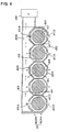
- Fig. 7 is a lengthwise cross-section view of the power supply apparatus shown in Fig. 4.
- Fig. 8 is an oblique cross-section view of another embodiment of the power supply apparatus of the present invention.
- Fig. 9 is a cross-section view of another embodiment of the power supply apparatus of the present invention.
- Fig. 10 is a cross-section view of another embodiment of the power supply apparatus of the present invention.
-
- The power supply apparatus shown In Figs. 3 and 4 is provided with a plurality of
power modules 31 41, a holder-case 32 42 which houses thesepower modules 31 41, and afan 39 49 to coolpower modules 31 41 in the holder-case 32 42. The holder-case 32 42 holds thepower modules 31 41 arranged in a parallel fashion of a plurality of rows, and cools thepower modules 31 41 with air which passes through the case. - A
power module 31 41 Is a plurality of rechargeable batteries or high capacitance super-capacitors joined In a linear fashion. For example,power modules 31 41 may have six series connected rechargeable batteries joined in a straight line. A power module using super-capacitors has a plurality of super-capacitors connected in parallel or series. However, a power module may also be made up of a single rechargeable battery or super-capacitor. Thepower module 31 shown in Fig. 5 has circular cylindricalrechargeable batteries 36 joined in a straight line by dish-shapedconnectors 37.Electrode terminals 35 comprising apositive electrode terminal 35A and anegative electrode terminal 35B are connected at the ends of apower module 31. - The structure for connecting
rechargeable batteries 36 in a straight line with dish-shapedconnectors 37 is shown Figs. 5 and 6. In apower module 31 of this structure, adisk region 37A of a dish-shapedconnector 37 is weld-connected to the positive terminal of a circularcylindrical battery 36. Thedisk region 37A of the dish-shapedconnector 37 is provided withprojections 37a for welding to the positive terminal of the circularcylindrical battery 36. When theprojections 37a of the dish-shapedconnector 37 are welded to the positive terminal, welding electrode rods push on the top surfaces of theprojections 37a. To prevent short circuits between the dish-shapedconnector 37 and the circularcylindrical battery 36, a ring-shapedInsulator 38 is sandwiched between the dish-shaped connector 7 and the circularcylindrical battery 36. - In addition, a circular
cylindrical battery 36 Is inserted into the dish-shapedconnector 37flange region 37B to connect the negative terminal of the circularcylindrical battery 36, which is itsouter case 36A, with theflange region 37B. Similar to thedisk region 37A, theflange region 37B also hasprojections 37a provided on its inner surface for welding to the batteryouter case 36A. During welding, welding electrode rods push on the outsides of theflange region 37Bprojections 37a. - Although not Illustrated, series connected batteries can be joined without using dish-shaped connectors by weld-connection to the facing sides of lead-plates bent In U-shapes. In this power module, battery terminals are welded to facing sides of U-shaped lead-plates by passing a high current pulse through the batteries in the direction of battery discharge. Further, metal plates can also be sandwiched between positive and negative battery terminals, and a high current pulse can be passed through the batteries in their direction of discharge to weld the metal plates to the battery terminals.
- Still further, positive and negative battery terminals of a power module can also be directly welded together with no intervening metal plate between batteries. Here, conical projections are provided on the upper surface of a battery sealing plate, which Is the positive electrode terminal, and these projections are welded to the negative electrode terminal of an adjacent battery by passing of a high current pulse.
-
Power modules 31, which have a plurality ofrechargeable batteries 36 connected in series, have the positive side of thebatteries 36 connected to apositive terminal 35A and the negative side connected to anegative terminal 35B. -
Rechargeable batteries 36 of thepower modules 31 are nickel-hydrogen batteries. However, batteries such as nickel-cadmium batteries or lithium-ion batteries may also be used as therechargeable batteries 36 of thepower modules 31. - Although not illustrated, temperature sensors are fixed to the surface of each rechargeable battery of the power modules. Temperature sensors are devices which can measure battery temperature. Preferably, PTC devices which change electrical resistance with battery temperature are used as temperature sensors. Temperature sensors fixed to the surface of each battery are connected linearly and in series via sensor leads, which extend along, and are fixed lengthwise to the surface of the power modules. Temperature sensors and sensor leads are bonded to battery surfaces, or for configurations with materials such as heat-shrink tubing covering battery surfaces, sensors and leads may also be attached via the heat-shrink tubing. However, in the power supply apparatus of the present invention, since one row of
power modules 31 41 is housed in apartition 34 44, there is no requirement to insulatepower modules 31 41 fromadjacent power modules 31 41. Consequently, It Is not necessary to always insulatepower modules 31 41 by covering them with heat-shrink tubing. - As shown In Figs. 3 and 4, the holder-
case 32 42 is box shaped having afirst 42a and asurface plate 32asecond 42b as opposing surfaces, A plurality of rows ofsurface plate 32bpower modules 31 41 are arranged side-by-side in a single plane parallel to thefirst 42a andsurface plate 32asecond 42b.surface plate 32b - The holder-
case 32 42 is provided with upper and lower cover-casings. The cover-casings are made up of a first cover-casing 32Aa 42Aa formed as a single unit with thefirst 42a, and a second cover-casing 32Ab 42Ab formed as a single unit with thesurface plate 32asecond 42b. The cover-casings are formed overall from plastic, and assembly primarily of these casings results in the holder-surface plate 32bcase 32 42. - In addition, As shown in Figs. 3 and 4, the holder-
case 32 42 is provided withwalls 33 43 between thepower modules 31 41 which are housed side-by-side. Thewalls 33 43 are formed by single piece construction with the first cover-casing 32Aa 42Aa and the second cover-casing 32Ab 42Ab, and extend from thefirst 42a to thesurface plate 32asecond 42b to form a plurality ofsurface plate 32bpartitions 34 44 inside thefirst 42a and thesurface plate 32asecond 42b,surface plate 32bWalls 33 43 formed as single units with the first cover-casing 32Aa 42Aa and the second cover-casing 32Ab 42Ab are joined without gaps at interfaces to formpartitions 34 44 which do not leak air from one to another. -
Power modules 31 41 are disposed In eachpartition 34 44. In the holder-case 32 42 of the figures, one row ofpower modules 31 41 Is disposed in eachpartition 34 44. As shown in Fig. 7, retainingprojections 410 are provided protruding frompartition 44 walls to holdpower modules 41 In fixed positions within thepartitions 44. Retainingprojections 410 are formed as single pieces with the plasticfirst surface plate 42a andsecond surface plate 42b, andpower modules 41 are retained In fixed positions by sandwiching them between the retainingprojections 410 of both surface plates.Power modules 41 are held by the retainingprojections 410 in a manner that creates gaps through which air can flow between thepower modules 41 and the Inside surfaces of thepartitions 44. Retainingprojections 410 shown in Fig. 7 are established as ribs which extend laterally with respect to thepower modules 41. - The holder-
case 32 42 divides the flow of cooling air and passes it through eachpartition 34 44. To realize this, flowinlets 313 413 are opened through thefirst 42a to divide the air flow and direct It into eachsurface plate 32apartition 34 44, andexhaust outlets 314 414 are opened through thesecond 42b to expel air from eachsurface plate 32bpartition 34 44 to the outside, as shown in Figs. 3 and 4. - The holder-
case 32 42 of these figures has valley regions betweenadjacent power modules 31 41 formed in the shape of grooves, and the lateral cross-sections ofpartition 34 44 interiors take on octagon shapes. Compared withpartition 34 44 interiors having square lateral cross-sections, thesepartition 34 44 inside walls have shapes which come closer to followingpower module 31 41 surface contours. Coolingducts 317 417, which deliver air and cool thepower modules 31 41, are established betweenpartition 34 44 Inside walls andpower modules 31 41. Compared withpartition 34 44 interiors having square lateral cross-sections,partition 34 44 interiors having octagon shaped lateral cross-sections have the characteristic that gaps forming the coolingducts 317 417 can be made more uniform In width. - Further, as shown In Fig. 8,
partitions 84 which contain circularcylindrical power modules 81 can have Inside walls with circular lateral cross-sections. Specifically,partitions 84 can be circular columns to allow even moreuniform cooling duct 817 width betweenpartition 84 inside walls andpower modules 81. Still further,partitions 84 which contain circularcylindrical power modules 81 may also have elliptical lateral cross-sections. - In the holder-
case 32 42 of Figs. 3, and 4, slit shapedflow inlets 313 413 andexhaust outlets 314 414 are opened betweenwalls 33 43 and located at the center regions ofpartitions 34 44. The holder-case 32 42 hasflow inlets 313 413 opened through thefirst 42a andsurface plate 32aexhaust outlets 314 414 opened through thesecond 42b. The slit shapedsurface plate 32bflow inlets 313 413 andexhaust outlets 314 414 extend along the lengthwise direction of thepower modules 31 41. This configuration of holder-case 32 42 has the characteristic that cooling air can be made to flow rapidly overpower module 31 41 surfaces for efficient cooling. - The power supply apparatus of Fig. 3 Is provided with an
air Inlet duct 315 at the surface of thefirst surface plate 32a. Theair inlet duct 315 connects with afan 39, and thefan 39 forcibly supplies cooling air into theInlet duct 315.Inlet duct 315 cooling air flow Is divided among eachflow inlet 313 and introduced Into eachpartition 34. To pass cooling air equally through allpartitions 34 of the power supply apparatus shown in Fig. 3, flowinlets 313 at the upstream end of theair inlet duct 315 are made smaller thanflow Inlets 313 at the downstream end of theair inlet duct 315. Since cooling air supplied by thefan 39 has high pressure at the upstream end of theair inlet duct 315, large quantities of air can be supplied throughsmall flow inlets 313. Since cooling air pressure decreases at the downstream end of theair Inlet duct 315,flow Inlet 313 size is increased to Increase the amount of air supplied to thedownstream partitions 34. Consequently, this configuration of power supply apparatus can supply cooling air uniformly to allpartitions 34. - The power supply apparatus of Fig. 4 Is provided with an
outlet duct 416 at the surface of thesecond surface plate 42b. Theoutlet duct 416 connects with afan 49, and the fan 9 forcibly Intakes cooling air from theoutlet duct 416 and exhausts It. Theoutlet duct 416 combines air flow expelled from eachpartition 44 and exhausts it outside the system. To pass cooling air equally through allpartitions 44 of the power supply apparatus shown in Fig. 4,exhaust outlets 414 at the upstream end of theoutlet duct 416 are made larger thanexhaust outlets 414 at the downstream end of theoutlet duct 416. Since thefan 49 efficiently Intakes cooling air at the downstream end of theoutlet duct 416, large quantities of air can be expelled fromsmall exhaust outlets 414. Consequently, this configuration of power supply apparatus can pass cooling air uniformly through allpartitions 44. - Further, the power supply apparatus shown in Figs. 9 and 10 have two tiered holder-
cases 92 102 with the two tiers disposed in a parallel fashion in mutual opposition around theair Inlet duct 915 oroutlet duct 1016. The power supply apparatus of Fig. 9 is provided with anair inlet duct 915 atfirst surface plate 92a surfaces similar to Fig. 3 but with a pair of holder-case 92 tiers disposed on opposite sides of theair inlet duct 915. This power supply apparatus supplies cooling air from thefan 99 flowing in theair inlet duct 915 to holder-case 92 tiers disposed on both sides of theair inlet duct 915, and coolspower modules 91 disposed in single rows in each holder-case 92partition 94. In Fig. 9, 92b Is the second surface plate, 93 are the walls, 913 are the flow inlets, and 914 are the exhaust outlets. - The power supply apparatus of Fig. 10 Is provided with an
outlet duct 1016 atsecond surface plate 102b surfaces similar to Fig. 4 but with a pair of holder-case 102 tiers disposed on opposite sides of theoutlet duct 1016. In this power supply apparatus, thefan 109 connected to theoutlet duct 1016 forcibly intakes cooling air from both holder-case 102 tiers, and coolspower modules 101 disposed in single rows in eachpartition 104 of holder-case 102 tiers disposed on both sides of theoutlet duct 1016. In Fig. 10, 102a is the first surface plate, 103 are the walls, 1013 are the flow inlets, and 1014 are the exhaust outlets. - The power supply apparatus of Figs. 3 and 4 have
partitions 34 44 with inside wall lateral cross-sections shaped as octagons to allow nearlyuniform cooling duct 317 417 width. This in turn allows nearly uniform flow rate of air through the coolingducts 317 417, and prevents dead-air withinpartitions 34 44. However, since the power supply apparatus of the present Invention disposes power modules as a single row in eachpartition 94 104, even ifpartition 94 104 inside wall lateral cross-sections are square-shaped as shown in Figs. 9 and 10,power modules 91 101 can be sufficiently cooled. - As this invention may be embodied In several forms without departing from the spirit of essential characteristics thereof, the present embodiment is therefore illustrative and not restrictive, since the scope of the invention is defined by the appended claims rather than by the description preceding them, and all changes that fall within the meets and bounds of the claims or equivalence of such meets and bounds thereof are therefore intended to be embraced by the claims.
Claims (16)
- A power supply apparatus comprising:a plurality of power modules [1];a holder-case [2] which houses power modules [1] arranged in a parallel fashion in a plurality of rows, and which cools the power modules [1] with air passing through its interior;a fan [9] which forcibly supplies air to, or exhausts air from, the holder-case [2]; and wherein
the holder-case [2] is a box shape and has a first surface plate [2a] and a second surface plate [2b] as opposite surfaces, and a plurality of power modules [1] are arranged laterally, parallel, and in a single plane along the first surface plate [2a] and the second surface plate [2b];
the holder-case [2] is provided with walls [3] between the plurality of rows of power modules [1] housed in a lateral arrangement, the walls [3] extend from the first surface plate [2a] to the second surface plate [2b] to divide the interior into a plurality of rows of partitions [4], and one row of power modules [1] is disposed in each row of partitions [4];
flow inlets [13] are opened through the first surface plate [2a] of the holder-case [2] to divide air flow and induce air flow into the plurallty of rows of partition [4] cooling ducts [17], and exhaust outlets [14] are opened through the second surface plate [2b] to expel air to the outside which has passed through the plurality of rows of partition [4] cooling ducts [17]; and
air flow is divided and induced to flow through first surface plate [2a] flow inlets [13] into a plurality of rows of partitions [4] using a fan [9], air Is passed through cooling ducts [17] to cool power modules [1], air which has performed its cooling function is expelled from second surface plate [2b] exhaust outlets [14], and power modules [1] disposed in a plurality of rows of partitions [4] are cooled. - A power supply apparatus as recited in claim 1 wherein an air inlet duct [15] is provided at the surface of the first surface plate [2a].
- A power supply apparatus as recited in claim 2 wherein flow inlets [13] opened through the first surface plate [2a] are made smaller at the upstream end of the air inlet duct [15] than at the downstream end.
- A power supply apparatus as recited in claim 2 wherein two tiers of holder-case [2] are disposed parallel and in mutual opposition around the air inlet duct [15].
- A power supply apparatus as recited In claim 1 wherein an air outlet duct [16] is provided at the surface of the second surface plate [2b].
- A power supply apparatus as recited In claim 5 wherein exhaust outlets [14] opened through the second surface plate [2b] are made larger at the upstream end of the outlet duct [16] than at the downstream end.
- A power supply apparatus as recited in claim 5 wherein two tiers of holder-case [2] are disposed parallel and In mutual opposition around the outlet duct [16].
- A power supply apparatus as recited in claim 1 wherein the flow Inlets 13 and exhaust outlets are slits extending in the lengthwise direction of the power modules [1].
- A power supply apparatus as recited in claim 1 wherein power modules [1] are shaped as circular cylinders, lateral cross-sections of the inside walls of partitions [4] housing these power modules [1] are polygonal with greater than or equal to eight sides, cooling ducts [17] are established between power module [1] surfaces and partition [4] inside walls, and these cooling ducts [17] cause air flow in the partitions [4] to flow along power module [1] surfaces.
- A power supply apparatus as recited In claim 9 wherein cooling duct [17] width is nearly constant over the entire power module [1] circumference.
- A power supply apparatus as recited in claim 1 wherein power modules [1] are shaped as circular cylinders, lateral cross-sections of the Inside walls of partitions [4] housing these power modules [1] are circular to elliptical, cooling ducts [17] are established between power module [1] surfaces and partition [4] inside walls, and these cooling ducts [17] cause air flow in the partitions [4] to flow along power module [1] surfaces.
- A power supply apparatus as recited in claim 11 wherein cooling duct [17] width is nearly constant over the entire power module [1] circumference.
- A power supply apparatus as recited in claim 1 wherein the first surface plate [2a] and the second surface plate [2b] are provided with retaining projections [10] formed by single piece construction projecting from partition [4] Inside walls to retain power modules [1], and the ends of these retaining projections [10] contact power module [1] surfaces to hold power modules [1] inside the partitions [4].
- A power supply apparatus as recited in claim 1 wherein power modules [1] have circular column shape and power modules [1] are disposed at partition [4] centers.
- A power supply apparatus as recited in claim 1 wherein the power modules [1] are a plurality of rechargeable batteries [6] connected in a linear fashion.
- A power supply apparatus as recited in claim 1 wherein the power modules [1] are high static charge capacity super capacitors connected in a linear fashion.
Applications Claiming Priority (2)
| Application Number | Priority Date | Filing Date | Title |
|---|---|---|---|
| JP2000333926A JP4118014B2 (en) | 2000-10-31 | 2000-10-31 | Power supply |
| JP2000333926 | 2000-10-31 |
Publications (3)
| Publication Number | Publication Date |
|---|---|
| EP1202359A2 true EP1202359A2 (en) | 2002-05-02 |
| EP1202359A3 EP1202359A3 (en) | 2003-12-17 |
| EP1202359B1 EP1202359B1 (en) | 2009-01-14 |
Family
ID=18809926
Family Applications (1)
| Application Number | Title | Priority Date | Filing Date |
|---|---|---|---|
| EP20010125807 Expired - Lifetime EP1202359B1 (en) | 2000-10-31 | 2001-10-29 | Cooling arrangement for power supply apparatus |
Country Status (8)
| Country | Link |
|---|---|
| US (1) | US6606245B2 (en) |
| EP (1) | EP1202359B1 (en) |
| JP (1) | JP4118014B2 (en) |
| KR (1) | KR100456349B1 (en) |
| CN (1) | CN1227769C (en) |
| DE (1) | DE60137395D1 (en) |
| HK (1) | HK1044415B (en) |
| TW (1) | TW522588B (en) |
Cited By (7)
| Publication number | Priority date | Publication date | Assignee | Title |
|---|---|---|---|---|
| EP1835251A1 (en) * | 2006-02-22 | 2007-09-19 | Behr GmbH & Co. KG | Device for cooling electrical elements |
| US7642006B2 (en) | 2004-11-29 | 2010-01-05 | Samsung Sdi Co., Ltd. | Secondary battery module |
| DE102009050960A1 (en) * | 2009-10-28 | 2011-05-12 | Voith Patent Gmbh | energy storage |
| EP2385566A1 (en) * | 2010-05-03 | 2011-11-09 | Samsung SDI Co., Ltd. | Rechargeable battery assembly |
| WO2015086669A3 (en) * | 2013-12-10 | 2015-08-27 | Akasol Gmbh | Tier element, lateral part and a cooling module as well as a method for producing a cooling module |
| DE102006011537B4 (en) | 2006-03-14 | 2020-07-02 | Volkswagen Ag | Energy storage for a motor vehicle with a hybrid drive |
| EP3926704A1 (en) * | 2020-06-18 | 2021-12-22 | VARTA Microbattery GmbH | Battery module with air cooling |
Families Citing this family (43)
| Publication number | Priority date | Publication date | Assignee | Title |
|---|---|---|---|---|
| CN1295812C (en) * | 2002-08-26 | 2007-01-17 | 松下电池工业株式会社 | Battery supply device |
| US20040131927A1 (en) * | 2003-01-03 | 2004-07-08 | Arthur Holland | Battery with insulative tubular housing |
| JP4675555B2 (en) * | 2003-07-18 | 2011-04-27 | 本田技研工業株式会社 | Battery powered power supply |
| US20050064785A1 (en) * | 2003-09-16 | 2005-03-24 | New Bright Industrial Co., Ltd. | High performance rechargeable battery pack for toy vehicles |
| TW200612594A (en) * | 2004-10-07 | 2006-04-16 | Pihsiang Machinery Co Ltd | Ventilation structure in a battery case for controlling the temperature therein |
| KR100853621B1 (en) * | 2004-10-26 | 2008-08-25 | 주식회사 엘지화학 | Cooling System For Battery Pack |
| KR100669410B1 (en) * | 2004-11-29 | 2007-01-15 | 삼성에스디아이 주식회사 | Secondary battery module |
| JP5190356B2 (en) * | 2005-03-16 | 2013-04-24 | フォード グローバル テクノロジーズ、リミテッド ライアビリティ カンパニー | Power supply system |
| US7967506B2 (en) | 2005-03-16 | 2011-06-28 | Ford Global Technologies, Llc | Power supply temperature sensor and system |
| US7604896B2 (en) | 2005-03-16 | 2009-10-20 | Ford Global Technologies, Llc | High voltage battery assembly for a motor vehicle |
| US8816645B2 (en) | 2005-07-20 | 2014-08-26 | Aerovironment, Inc. | Integrated battery unit with cooling and protection expedients for electric vehicles |
| KR100648704B1 (en) * | 2005-07-29 | 2006-11-23 | 삼성에스디아이 주식회사 | Secondary battery module |
| US20070024245A1 (en) * | 2005-08-01 | 2007-02-01 | Ford Global Technologies, Llc | Power supply apparatus and a vehicle having a power supply apparatus |
| JP4663464B2 (en) * | 2005-09-22 | 2011-04-06 | 本田技研工業株式会社 | Power storage device equipped vehicle |
| KR100805114B1 (en) * | 2006-04-25 | 2008-02-21 | 삼성에스디아이 주식회사 | Secondary battery module |
| US20070289561A1 (en) * | 2006-06-14 | 2007-12-20 | Steve Cox | Electric vehicle air cooling system |
| CN101542774B (en) * | 2006-08-29 | 2012-10-03 | 江森自控帅福得先进能源动力系统有限责任公司 | Battery module |
| US7735331B2 (en) * | 2006-09-20 | 2010-06-15 | Ford Global Technologies, Llc | System and method for controlling temperature of an energy storage device in a vehicle |
| KR100836398B1 (en) * | 2006-12-12 | 2008-06-09 | 현대자동차주식회사 | Holder for cooling of battery module |
| WO2008095313A1 (en) * | 2007-02-09 | 2008-08-14 | Advanced Lithium Power Inc. | Battery thermal management system |
| WO2008153602A1 (en) * | 2007-03-01 | 2008-12-18 | Johnson Controls-Saft Advanced Power Solutions Llc | Battery module |
| JP5119735B2 (en) * | 2007-05-16 | 2013-01-16 | ソニー株式会社 | Battery pack |
| DE102008051085A1 (en) * | 2008-10-09 | 2010-04-15 | Dr.Ing.H.C.F.Porsche Aktiengesellschaft | battery assembly |
| US8598852B2 (en) * | 2008-11-12 | 2013-12-03 | American Axle & Manufacturing, Inc. | Cost effective configuration for supercapacitors for HEV |
| US20100157527A1 (en) * | 2008-12-23 | 2010-06-24 | Ise Corporation | High-Power Ultracapacitor Energy Storage Pack and Method of Use |
| KR101143279B1 (en) | 2009-08-20 | 2012-05-11 | 주식회사 엘지화학 | Battery Pack Having Novel Cooling Structure |
| JP5556491B2 (en) * | 2010-08-06 | 2014-07-23 | 株式会社豊田自動織機 | Battery pack |
| CN101973322A (en) * | 2010-09-28 | 2011-02-16 | 上海奕洁汽车科技有限公司 | Electric automobile |
| JP5639835B2 (en) * | 2010-09-30 | 2014-12-10 | 株式会社リチウムエナジージャパン | Battery pack and electric vehicle equipped with the same |
| FR2965756B1 (en) * | 2010-10-07 | 2012-11-02 | Renault Sa | BATTERY COMPARTMENT FOR A VEHICLE |
| US9118093B2 (en) * | 2013-01-03 | 2015-08-25 | Caterpillar Inc. | Cooling jacket for battery pack |
| KR101936962B1 (en) * | 2013-06-28 | 2019-01-09 | 현대자동차주식회사 | Battery cooling system for vehicle |
| JP6149610B2 (en) * | 2013-08-28 | 2017-06-21 | 株式会社デンソー | Battery cooling device |
| DE102014207403A1 (en) * | 2014-04-17 | 2015-10-22 | Robert Bosch Gmbh | Battery unit with a receiving device and a plurality of electrochemical cells and battery module with a plurality of such battery units |
| JP6098610B2 (en) * | 2014-10-17 | 2017-03-22 | トヨタ自動車株式会社 | Power storage device |
| JP6693338B2 (en) * | 2016-08-26 | 2020-05-13 | 株式会社デンソー | Battery pack |
| KR101830158B1 (en) * | 2016-11-08 | 2018-02-21 | 계양전기 주식회사 | Battery pack with cooling structure |
| KR102207881B1 (en) | 2017-01-17 | 2021-01-25 | 주식회사 엘지화학 | Battery module, battery pack comprising the battery module and vehicle comprising the battery pack |
| KR102201348B1 (en) | 2017-01-17 | 2021-01-08 | 주식회사 엘지화학 | Fabricating method of battery module |
| KR102142669B1 (en) | 2017-02-24 | 2020-08-07 | 주식회사 엘지화학 | Air cooling type Battery Module having Guide vane |
| US10034410B1 (en) * | 2017-04-26 | 2018-07-24 | Chroma Ate Inc. | Support apparatus |
| CN109244592A (en) * | 2018-09-20 | 2019-01-18 | 浙江中车电车有限公司 | A kind of air-cooled structure and battery case |
| DE102020129668A1 (en) | 2020-11-11 | 2022-05-12 | Audi Aktiengesellschaft | Round cell cooling device for cooling round cells of a battery, manufacturing method for a round cell cooling device and motor vehicle with a round cell cooling device |
Citations (3)
| Publication number | Priority date | Publication date | Assignee | Title |
|---|---|---|---|---|
| JPH10270095A (en) | 1997-03-24 | 1998-10-09 | Toyota Motor Corp | Battery power source cooling device |
| JPH11329518A (en) | 1998-05-21 | 1999-11-30 | Toshiba Battery Co Ltd | Battery system |
| JP2000333926A (en) | 1999-05-31 | 2000-12-05 | Matsushita Electric Ind Co Ltd | Body fat measuring device |
Family Cites Families (14)
| Publication number | Priority date | Publication date | Assignee | Title |
|---|---|---|---|---|
| FR2343974A1 (en) * | 1976-03-10 | 1977-10-07 | Honeywell Bull Soc Ind | VENTILATION ENCLOSURE |
| US4395468A (en) * | 1980-12-22 | 1983-07-26 | Westinghouse Electric Corp. | Fuel cell generator |
| US4578324A (en) * | 1984-10-05 | 1986-03-25 | Ford Aerospace & Communications Corporation | Active cooling system for electrochemical cells |
| CH680693A5 (en) * | 1990-08-07 | 1992-10-15 | Sulzer Ag | |
| US5585204A (en) * | 1993-12-27 | 1996-12-17 | Honda Giken Kogyo Kabushiki Kaisha | Temperature control structure for batteries and battery box for housing such batteries |
| US5753384A (en) * | 1995-05-25 | 1998-05-19 | Electric Fuel (E.F.L.) Ltd. | Air-cooled metal-air battery |
| US5879833A (en) * | 1996-06-12 | 1999-03-09 | Matsushita Electric Industrial Co., Ltd. | Power supply unit and heat radiation method therefor |
| DE69823745T2 (en) * | 1997-03-24 | 2004-10-07 | Toyota Motor Co Ltd | Power supply unit containing modular battery |
| US6011688A (en) * | 1997-06-04 | 2000-01-04 | Hewlett Packard Co. | Compact apparatus for cooling a plurality of circuit packs arranged with a cage |
| US6105875A (en) * | 1998-09-08 | 2000-08-22 | Lucent Technologies, Inc. | Direct air cooling of outdoor electronic cabinets |
| DE10003247B4 (en) * | 1999-01-29 | 2005-02-24 | Sanyo Electric Co., Ltd., Moriguchi | Power source, equipped with rechargeable batteries |
| DE10064648C2 (en) * | 1999-12-28 | 2003-09-18 | Honda Motor Co Ltd | battery unit |
| JP4233733B2 (en) * | 2000-07-17 | 2009-03-04 | パナソニック株式会社 | Power supply device and manufacturing method thereof |
| JP4046463B2 (en) * | 2000-08-03 | 2008-02-13 | 三洋電機株式会社 | Power supply |
-
2000
- 2000-10-31 JP JP2000333926A patent/JP4118014B2/en not_active Expired - Fee Related
-
2001
- 2001-10-26 CN CNB011342293A patent/CN1227769C/en not_active Expired - Fee Related
- 2001-10-29 EP EP20010125807 patent/EP1202359B1/en not_active Expired - Lifetime
- 2001-10-29 TW TW90126795A patent/TW522588B/en not_active IP Right Cessation
- 2001-10-29 DE DE60137395T patent/DE60137395D1/en not_active Expired - Lifetime
- 2001-10-30 US US09/984,484 patent/US6606245B2/en not_active Expired - Fee Related
- 2001-10-30 KR KR10-2001-0067012A patent/KR100456349B1/en not_active IP Right Cessation
-
2002
- 2002-08-16 HK HK02105994.3A patent/HK1044415B/en not_active IP Right Cessation
Patent Citations (3)
| Publication number | Priority date | Publication date | Assignee | Title |
|---|---|---|---|---|
| JPH10270095A (en) | 1997-03-24 | 1998-10-09 | Toyota Motor Corp | Battery power source cooling device |
| JPH11329518A (en) | 1998-05-21 | 1999-11-30 | Toshiba Battery Co Ltd | Battery system |
| JP2000333926A (en) | 1999-05-31 | 2000-12-05 | Matsushita Electric Ind Co Ltd | Body fat measuring device |
Cited By (10)
| Publication number | Priority date | Publication date | Assignee | Title |
|---|---|---|---|---|
| US7642006B2 (en) | 2004-11-29 | 2010-01-05 | Samsung Sdi Co., Ltd. | Secondary battery module |
| EP1835251A1 (en) * | 2006-02-22 | 2007-09-19 | Behr GmbH & Co. KG | Device for cooling electrical elements |
| DE102006011537B4 (en) | 2006-03-14 | 2020-07-02 | Volkswagen Ag | Energy storage for a motor vehicle with a hybrid drive |
| DE102009050960A1 (en) * | 2009-10-28 | 2011-05-12 | Voith Patent Gmbh | energy storage |
| DE102009050960B4 (en) * | 2009-10-28 | 2012-04-05 | Voith Patent Gmbh | Energy storage and method for cooling such energy storage |
| EP2385566A1 (en) * | 2010-05-03 | 2011-11-09 | Samsung SDI Co., Ltd. | Rechargeable battery assembly |
| US8828586B2 (en) | 2010-05-03 | 2014-09-09 | Samsung Sdi Co., Ltd. | Rechargeable battery pack and connection tab used for the same |
| WO2015086669A3 (en) * | 2013-12-10 | 2015-08-27 | Akasol Gmbh | Tier element, lateral part and a cooling module as well as a method for producing a cooling module |
| EP3926704A1 (en) * | 2020-06-18 | 2021-12-22 | VARTA Microbattery GmbH | Battery module with air cooling |
| WO2021254941A1 (en) * | 2020-06-18 | 2021-12-23 | Varta Microbattery Gmbh | Battery module with air cooling capability |
Also Published As
| Publication number | Publication date |
|---|---|
| US20020085355A1 (en) | 2002-07-04 |
| US6606245B2 (en) | 2003-08-12 |
| EP1202359A3 (en) | 2003-12-17 |
| HK1044415A1 (en) | 2002-10-18 |
| CN1351387A (en) | 2002-05-29 |
| EP1202359B1 (en) | 2009-01-14 |
| KR20020033561A (en) | 2002-05-07 |
| KR100456349B1 (en) | 2004-11-09 |
| DE60137395D1 (en) | 2009-03-05 |
| JP2002141113A (en) | 2002-05-17 |
| TW522588B (en) | 2003-03-01 |
| HK1044415B (en) | 2006-03-10 |
| JP4118014B2 (en) | 2008-07-16 |
| CN1227769C (en) | 2005-11-16 |
Similar Documents
| Publication | Publication Date | Title |
|---|---|---|
| EP1202359A2 (en) | Cooling arrangement for power supply apparatus | |
| US6445582B1 (en) | Power supply apparatus | |
| JP4659699B2 (en) | Battery module | |
| EP1872419B1 (en) | Housing member for battery module | |
| JP4646867B2 (en) | Battery module | |
| US9559393B2 (en) | Battery module thermal management fluid guide assembly | |
| JP3829396B2 (en) | Battery power cooling system | |
| US6953638B2 (en) | Fluid-cooled battery pack system | |
| US6479185B1 (en) | Extended life battery pack with active cooling | |
| CN100502095C (en) | Rechargeable battery module | |
| US20060078789A1 (en) | Battery comprising at least one electrochemical storage cell and a cooling device | |
| JP4136269B2 (en) | Power supply | |
| JPH10270006A (en) | Battery power supply and end plate used therein | |
| JP2005183217A (en) | Vehicular power supply apparatus | |
| JP5096842B2 (en) | Battery storage unit | |
| JP4086490B2 (en) | Power supply | |
| KR100684760B1 (en) | Secondary battery module | |
| JP2004130910A (en) | Battery module | |
| CN113451695A (en) | Battery module and electric vehicle | |
| JPH08268083A (en) | Battery structure of electric vehicle | |
| JP4043167B2 (en) | Power supply | |
| JP4484653B2 (en) | Power supply |
Legal Events
| Date | Code | Title | Description |
|---|---|---|---|
| PUAI | Public reference made under article 153(3) epc to a published international application that has entered the european phase |
Free format text: ORIGINAL CODE: 0009012 |
|
| AK | Designated contracting states |
Kind code of ref document: A2 Designated state(s): AT BE CH CY DE DK ES FI FR GB GR IE IT LI LU MC NL PT SE TR |
|
| AX | Request for extension of the european patent |
Free format text: AL;LT;LV;MK;RO;SI |
|
| PUAL | Search report despatched |
Free format text: ORIGINAL CODE: 0009013 |
|
| AK | Designated contracting states |
Kind code of ref document: A3 Designated state(s): AT BE CH CY DE DK ES FI FR GB GR IE IT LI LU MC NL PT SE TR |
|
| AX | Request for extension of the european patent |
Extension state: AL LT LV MK RO SI |
|
| RIC1 | Information provided on ipc code assigned before grant |
Ipc: 7B 60K 1/04 B Ipc: 7H 01G 1/08 B Ipc: 7H 01M 2/00 A Ipc: 7B 60K 6/04 B Ipc: 7H 01M 10/50 B |
|
| 17P | Request for examination filed |
Effective date: 20040130 |
|
| AKX | Designation fees paid |
Designated state(s): DE FR IT SE |
|
| 17Q | First examination report despatched |
Effective date: 20070315 |
|
| GRAP | Despatch of communication of intention to grant a patent |
Free format text: ORIGINAL CODE: EPIDOSNIGR1 |
|
| RIC1 | Information provided on ipc code assigned before grant |
Ipc: H01M 10/50 20060101ALI20080618BHEP Ipc: H01M 2/10 20060101ALI20080618BHEP Ipc: B60K 1/04 20060101AFI20080618BHEP |
|
| GRAS | Grant fee paid |
Free format text: ORIGINAL CODE: EPIDOSNIGR3 |
|
| GRAA | (expected) grant |
Free format text: ORIGINAL CODE: 0009210 |
|
| AK | Designated contracting states |
Kind code of ref document: B1 Designated state(s): DE FR IT SE |
|
| REF | Corresponds to: |
Ref document number: 60137395 Country of ref document: DE Date of ref document: 20090305 Kind code of ref document: P |
|
| PG25 | Lapsed in a contracting state [announced via postgrant information from national office to epo] |
Ref country code: SE Free format text: LAPSE BECAUSE OF FAILURE TO SUBMIT A TRANSLATION OF THE DESCRIPTION OR TO PAY THE FEE WITHIN THE PRESCRIBED TIME-LIMIT Effective date: 20090414 |
|
| PLBE | No opposition filed within time limit |
Free format text: ORIGINAL CODE: 0009261 |
|
| STAA | Information on the status of an ep patent application or granted ep patent |
Free format text: STATUS: NO OPPOSITION FILED WITHIN TIME LIMIT |
|
| 26N | No opposition filed |
Effective date: 20091015 |
|
| REG | Reference to a national code |
Ref country code: DE Ref legal event code: R082 Ref document number: 60137395 Country of ref document: DE Representative=s name: SCHUMACHER & WILLSAU PATENTANWALTSGESELLSCHAFT, DE |
|
| PGFP | Annual fee paid to national office [announced via postgrant information from national office to epo] |
Ref country code: IT Payment date: 20121016 Year of fee payment: 12 |
|
| PGFP | Annual fee paid to national office [announced via postgrant information from national office to epo] |
Ref country code: FR Payment date: 20131009 Year of fee payment: 13 Ref country code: DE Payment date: 20131023 Year of fee payment: 13 |
|
| PG25 | Lapsed in a contracting state [announced via postgrant information from national office to epo] |
Ref country code: IT Free format text: LAPSE BECAUSE OF NON-PAYMENT OF DUE FEES Effective date: 20131029 |
|
| REG | Reference to a national code |
Ref country code: DE Ref legal event code: R119 Ref document number: 60137395 Country of ref document: DE |
|
| PG25 | Lapsed in a contracting state [announced via postgrant information from national office to epo] |
Ref country code: DE Free format text: LAPSE BECAUSE OF NON-PAYMENT OF DUE FEES Effective date: 20150501 |
|
| REG | Reference to a national code |
Ref country code: FR Ref legal event code: ST Effective date: 20150630 |
|
| PG25 | Lapsed in a contracting state [announced via postgrant information from national office to epo] |
Ref country code: FR Free format text: LAPSE BECAUSE OF NON-PAYMENT OF DUE FEES Effective date: 20141031 |