EP1189187A2 - Method and system for monitoring a designated area - Google Patents
Method and system for monitoring a designated area Download PDFInfo
- Publication number
- EP1189187A2 EP1189187A2 EP01119125A EP01119125A EP1189187A2 EP 1189187 A2 EP1189187 A2 EP 1189187A2 EP 01119125 A EP01119125 A EP 01119125A EP 01119125 A EP01119125 A EP 01119125A EP 1189187 A2 EP1189187 A2 EP 1189187A2
- Authority
- EP
- European Patent Office
- Prior art keywords
- area
- image
- detection
- monitoring
- data
- Prior art date
- Legal status (The legal status is an assumption and is not a legal conclusion. Google has not performed a legal analysis and makes no representation as to the accuracy of the status listed.)
- Granted
Links
Images


Classifications
-
- G—PHYSICS
- G08—SIGNALLING
- G08B—SIGNALLING OR CALLING SYSTEMS; ORDER TELEGRAPHS; ALARM SYSTEMS
- G08B13/00—Burglar, theft or intruder alarms
- G08B13/18—Actuation by interference with heat, light, or radiation of shorter wavelength; Actuation by intruding sources of heat, light, or radiation of shorter wavelength
- G08B13/189—Actuation by interference with heat, light, or radiation of shorter wavelength; Actuation by intruding sources of heat, light, or radiation of shorter wavelength using passive radiation detection systems
- G08B13/194—Actuation by interference with heat, light, or radiation of shorter wavelength; Actuation by intruding sources of heat, light, or radiation of shorter wavelength using passive radiation detection systems using image scanning and comparing systems
- G08B13/196—Actuation by interference with heat, light, or radiation of shorter wavelength; Actuation by intruding sources of heat, light, or radiation of shorter wavelength using passive radiation detection systems using image scanning and comparing systems using television cameras
- G08B13/19665—Details related to the storage of video surveillance data
- G08B13/19669—Event triggers storage or change of storage policy
-
- G—PHYSICS
- G08—SIGNALLING
- G08B—SIGNALLING OR CALLING SYSTEMS; ORDER TELEGRAPHS; ALARM SYSTEMS
- G08B13/00—Burglar, theft or intruder alarms
- G08B13/18—Actuation by interference with heat, light, or radiation of shorter wavelength; Actuation by intruding sources of heat, light, or radiation of shorter wavelength
- G08B13/189—Actuation by interference with heat, light, or radiation of shorter wavelength; Actuation by intruding sources of heat, light, or radiation of shorter wavelength using passive radiation detection systems
- G08B13/194—Actuation by interference with heat, light, or radiation of shorter wavelength; Actuation by intruding sources of heat, light, or radiation of shorter wavelength using passive radiation detection systems using image scanning and comparing systems
- G08B13/196—Actuation by interference with heat, light, or radiation of shorter wavelength; Actuation by intruding sources of heat, light, or radiation of shorter wavelength using passive radiation detection systems using image scanning and comparing systems using television cameras
- G08B13/19602—Image analysis to detect motion of the intruder, e.g. by frame subtraction
- G08B13/19608—Tracking movement of a target, e.g. by detecting an object predefined as a target, using target direction and or velocity to predict its new position
-
- G—PHYSICS
- G08—SIGNALLING
- G08B—SIGNALLING OR CALLING SYSTEMS; ORDER TELEGRAPHS; ALARM SYSTEMS
- G08B13/00—Burglar, theft or intruder alarms
- G08B13/18—Actuation by interference with heat, light, or radiation of shorter wavelength; Actuation by intruding sources of heat, light, or radiation of shorter wavelength
- G08B13/189—Actuation by interference with heat, light, or radiation of shorter wavelength; Actuation by intruding sources of heat, light, or radiation of shorter wavelength using passive radiation detection systems
- G08B13/194—Actuation by interference with heat, light, or radiation of shorter wavelength; Actuation by intruding sources of heat, light, or radiation of shorter wavelength using passive radiation detection systems using image scanning and comparing systems
- G08B13/196—Actuation by interference with heat, light, or radiation of shorter wavelength; Actuation by intruding sources of heat, light, or radiation of shorter wavelength using passive radiation detection systems using image scanning and comparing systems using television cameras
- G08B13/19639—Details of the system layout
- G08B13/19641—Multiple cameras having overlapping views on a single scene
-
- G—PHYSICS
- G08—SIGNALLING
- G08B—SIGNALLING OR CALLING SYSTEMS; ORDER TELEGRAPHS; ALARM SYSTEMS
- G08B13/00—Burglar, theft or intruder alarms
- G08B13/18—Actuation by interference with heat, light, or radiation of shorter wavelength; Actuation by intruding sources of heat, light, or radiation of shorter wavelength
- G08B13/189—Actuation by interference with heat, light, or radiation of shorter wavelength; Actuation by intruding sources of heat, light, or radiation of shorter wavelength using passive radiation detection systems
- G08B13/194—Actuation by interference with heat, light, or radiation of shorter wavelength; Actuation by intruding sources of heat, light, or radiation of shorter wavelength using passive radiation detection systems using image scanning and comparing systems
- G08B13/196—Actuation by interference with heat, light, or radiation of shorter wavelength; Actuation by intruding sources of heat, light, or radiation of shorter wavelength using passive radiation detection systems using image scanning and comparing systems using television cameras
- G08B13/19639—Details of the system layout
- G08B13/19652—Systems using zones in a single scene defined for different treatment, e.g. outer zone gives pre-alarm, inner zone gives alarm
-
- G—PHYSICS
- G08—SIGNALLING
- G08B—SIGNALLING OR CALLING SYSTEMS; ORDER TELEGRAPHS; ALARM SYSTEMS
- G08B13/00—Burglar, theft or intruder alarms
- G08B13/18—Actuation by interference with heat, light, or radiation of shorter wavelength; Actuation by intruding sources of heat, light, or radiation of shorter wavelength
- G08B13/189—Actuation by interference with heat, light, or radiation of shorter wavelength; Actuation by intruding sources of heat, light, or radiation of shorter wavelength using passive radiation detection systems
- G08B13/194—Actuation by interference with heat, light, or radiation of shorter wavelength; Actuation by intruding sources of heat, light, or radiation of shorter wavelength using passive radiation detection systems using image scanning and comparing systems
- G08B13/196—Actuation by interference with heat, light, or radiation of shorter wavelength; Actuation by intruding sources of heat, light, or radiation of shorter wavelength using passive radiation detection systems using image scanning and comparing systems using television cameras
- G08B13/19697—Arrangements wherein non-video detectors generate an alarm themselves
Definitions
- the present invention relates to a method for monitoring a predetermined one Area that has at least two zones, one critical and one uncritical Represent the area and be separated from each other by an alarm limit, as well as a corresponding procedure.
- An exemplary security area is e.g. into a critical and an uncritical area divided, which are separated by an alarm limit.
- a variety of Video surveillance cameras are used to monitor this alarm limit.
- each Video surveillance camera is assigned a predetermined detection range, each a section of the security area visualized and part or all of it Field of view of the video surveillance camera includes an object that is in a certain detection area occurs, from the corresponding video surveillance camera is recorded. Furthermore, this video surveillance camera records the complete motion sequence of the object in its detection area, i.e. all changes of position of the Objects are perceived. In the event that the object is based on the uncritical Area exceeds the alarm limit in the direction of the critical area, triggers the Video surveillance camera alarm off.
- a major disadvantage of this method is that the alarm is triggered for the case that the security guard in the detection area of a first video surveillance camera exceeds the alarm limit from the critical towards the uncritical range, and in a detection range of a second video surveillance camera in returns the critical area beyond the alarm limit.
- the present invention Task based on creating a way when monitoring a predetermined Area with increased decision security to trigger alarm when an unauthorized Object enters a critical area.
- the object of the present invention is achieved by a method for monitoring a predetermined area solved using images, the images at least are generated by a first and a second image capturing device and the predetermined area has at least two zones that are critical and non-critical Represent areas that are separated by an alarm limit.
- a predetermined detection area is assigned to each image capture device, and an object that enters the detection area of an image capture device is from the corresponding image capture device. From this image capture device data is recorded, the changes in the position of the object in the corresponding Describe the detection area.
- An advantage of the transfer of the acquisition data to a first image acquisition device according to the invention to a second image capture device is that the second Image capture device has more data regarding the object being tracked, so that the decisive security when an alarm is triggered is increased significantly. Furthermore, this object transfer between the monitoring devices a complete monitoring of an object that is in the detection areas of several Image capture devices moved.
- the detection areas of the first and second image detection devices are preferably formed such that they overlap in an overlap area or adjoin each other.
- the first image capturing device transfers those recorded by it Data unsolicited to the second image capture device in the event that the first image detection device determines that the object is in the detection range of the second image capture device will occur.
- the second image capture device in the event that it is in the detection area assigned to it Detects an object and determines that this object was previously in the detection area the first image capture device was, the first image capture device for transfer of the data recorded on the object.
- the first image capturing device transfers the data recorded by it to an evaluation device, which via a Network is connected to the first and the second image capture device and which in turn transfers the data to the second image capturing device.
- the evaluation device can send its data to the second image acquisition device without being asked passed in case it is determined that the object is in the detection area the second image capture device will occur.
- the second image capturing device can be a variant if it detects an object, that enters the assigned detection area and that previously in the detection area of the first image capture device was the evaluation device for transferring the Prompt recorded data.
- the data indicate the change in the position of the object in the detection area describe an image capture device, at least information on, which have a motion vector, an average speed and motion direction components represents.
- Area data can thus be transmitted on the basis of this data, a section of the detection area of the second image capture device represent, in which the object based on the detection area of the first image detection device will occur.
- the data preferably have information which represents the section of the detection area of the second image detection device, will enter the object.
- one of the image capture devices must be in order to capture an object in the capture area a so-called detection threshold value is exceeded, wherein in the section of the detection area of the second image capture device into which the Object will occur, the detection threshold is lowered after experiencing the data, that were handed over by the first image capture device.
- An advantage of lowering the detection threshold is that the detection security of objects in the detection area of image capture devices, the Data passed by other image capture devices is increased. This is particularly advantageous in the event that an object e.g. due to different Visibility in the detection area of an image capture device can be detected very well while it is in the detection area of another, adjacent image detection device is difficult to see.
- those from the first image capture device to the second image capture device transferred data are used to identify the Object to perform, which is significantly simplified based on the data passed.
- the monitoring facilities 1, 2 can be designed as common video surveillance cameras or as infrared or thermal imaging cameras.
- the monitoring devices 1, 2 are preferred each mounted on masts 3, 4, which are fixed in a site to be monitored 8 are anchored.
- the monitoring devices 1, 2 can be connected to any rigid or moving objects, for example on parts of a building.
- both surveillance cameras each have a so-called Viewing area 6, 7 of a length 11.
- the length 11 of the viewing area 5, 6, 7 depends on an orientation angle ⁇ of the monitoring devices 1, 2, and the detection properties the corresponding monitoring devices 1, 2.
- Surveillance cameras correspond to the detection properties, for example the optical ones Properties of the camera optics used.
- the viewing areas 5, 6, 7 of different monitoring devices are preferably located 1, 2 such that they overlap each other by predetermined lengths 9, 10, so that a complete monitoring of the area to be monitored is made possible.
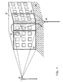
- FIG. 2 shows a three-dimensional illustration of the viewing areas 6, 7 of the monitoring devices 1, 2 from FIG. 1.
- the viewing areas 6, 7 are marked with a rectangular base with a base of length 11 shown, although in reality these viewing areas 6, 7 will generally be designed as so-called "viewing cones".
- the viewing areas 6, 7 preferably overlap one another in such a way that likewise larger objects, for example, starting from the viewing area 6 into the viewing area 7 occur, also in the overlap area of the viewing areas 6, 7 of the length 10 can be fully captured.
- FIG. 3 shows a top view of the arrangement of the monitoring devices 1, 2 according to FIG Fig. 1 in a first embodiment.
- the monitoring devices 1, 2 serve in the illustrated embodiment for this purpose, for example an unauthorized approach to prevent objects on a runway 12 on an airport site. This will by means of the monitoring devices 1, 2 a control line KL1 is monitored and if a Object starting from a permitted area EB this control line KL1 in the direction of If the taxiway exceeds 12, the alarm is triggered.
- a person or a vehicle along a the control line from the permitted area EB indicated by an arrow 13 KL1 in the direction of the taxiway 12 is exceeded when crossing the control line KL1 in point 16 alarm triggered.
- the corresponding object first enters the Viewing area 6 of the monitoring device 1 and then crosses this viewing area 6 and the overlap area that this viewing area 6 with the viewing area 7 of the monitoring device 2 forms.
- the object is registered at the time of its entry Field of view 6 captured by the monitoring device 1 and its movement is determined by means of Object tracking tracks to the point where the object is in the overlap area entry.
- Object tracking means that the entire movement of the object is recorded in the viewing area 6, 7 of the monitoring device 1, 2.
- the object becomes from the monitoring device 1 to the monitoring device 2 by means of so-called “Visual Handover "or object handover and then from the monitoring device 2 continues to point 16 where the alarm is triggered.
- “Visual Handover” or object transfer means that the monitoring device 1 recorded data relating to the object of the monitoring device 2 become.
- a second variant is indicated by means of an arrow 14, which illustrates that again any object such as a person or a vehicle along the direction of the arrow of the arrow 14 moves and the control line KL1 starting from the permitted area EB in the direction of the runway 12. This is when the control line is exceeded KL1 in point 17 alarm triggered.
- the corresponding object enters the viewing area 6 of FIG Monitoring device 1 and leaves this field of view 6 again before entering into the viewing area 7 of the monitoring device 2 and then crossing over the control line 1 in point 17.
- the object enters the viewing area 7 of the monitoring device 2 it is determined that this object has previously covered the viewing area 6 crossed the monitoring device 1, whereupon the object from the monitoring device 1 is transferred to the monitoring device 2.
- a third variant is shown by means of an arrow 15.
- the space between the Control line KL1 and taxiway 12 defined as a restricted area EEB by allowing certain objects to stay.
- the monitoring device In order to prevent such a false alarm from being triggered, the monitoring device must 2 the "history" of the control employee is known, i.e. in the present example the path taken by the control personnel along arrow 15 in the field of vision 6 has covered the monitoring device 1. Accordingly, object tracking of the control employee in both viewing areas 6, 7, and the monitoring device 1 and the monitoring device 2, when making a decision is taken into account, it can be determined that the control employee leaves the Intermediate space has crossed the control line KL1 and then again by crossing the control line KL1 has returned to this space. That means it can it is found that in the present example no alarm is triggered because the exceeding the control line KL1 is a justified crossing.
- Another major advantage of handing over the property is that the security of detection of objects in the viewing areas 6, 7 of the monitoring devices 1, 2 increased is what is explained in more detail below.
- an object enters the viewing area 6, where it is from the monitoring device 1 is detected and where changes in position of the object are tracked and corresponding Data is recorded.
- the notification preferably includes information regarding the direction in which the object is moving and the recorded data so that the monitoring device 2 can determine which location the object will enter into the viewing area 7. The monitoring device can thus 2 recognize the object more easily when entering the viewing area 7 and to capture.
- the detection and detection of the object by the monitoring devices 1, 2 in each of the viewing areas 6, 7 depends on a predetermined threshold value, which must be exceeded in order to record object data, for example trigger this threshold value in the monitoring device 2 is preferred based on the data sent by the monitoring device 1, so that the detection threshold is lowered accordingly. Lowering the Threshold value can take place for a sub-zone of the viewing area 7, into which the monitoring device 1 detected object is likely to occur, or for the complete Viewing area 7.
- a monitoring device 1, 2 that detects an occurrence of an object in their field of view 6, 7 is detected and changes in position of this object captures, record and analyze data to determine if the object may be from the Field of view 6, 7 of another monitoring device 1, 2 has occurred.
- the corresponding monitoring device 1, 2 can be positively analyzed by the other monitoring device 1, 2 data on the movement of the Request objects in the viewing area 6, 7 of this other monitoring device 1, 2.
- an interfering object such as a spider is located moved over a section of a monitoring device 1, 2 and recognized as an object because this object takes into account its determined direction of movement the viewing area 6, 7 of another monitoring device 1, 2 should come.
- the requesting monitoring device 1, 2 has no data relating to the detected Object received from another monitoring device 1, 2 can be assumed that the detected object is not alarm relevant.
- FIG. 4 shows an illustration of an arrangement of monitoring devices 19, 20 according to a further preferred embodiment of the present invention.
- the monitoring facilities 19, 20 can in turn be used as video surveillance cameras be executed or as infrared or thermal imaging cameras.
- the monitoring facilities 19, 20 are preferably each mounted on masts that are firmly in the ground are anchored.
- the monitoring devices 19, 20 can be connected to any rigid or moving objects, for example on parts of a building.
- the monitoring devices 19, 20 are used, for example, for Supervision of a prison building.
- the monitoring devices 19, 20 are designed as surveillance cameras, both have surveillance cameras each have a viewing area 21, 22.
- the size of the monitorable Viewing area 21, 22 depends on the orientation of the monitoring devices 19, 20, as well as the detection properties of the corresponding monitoring devices 19, 20.
- the detection properties correspond for example the optical properties of the camera optics used.
- the assumption is that an object, such as a security guard, from the roof 18 of the building via a fire escape 25 into an allowed area EB can arrive without triggering an alarm.
- an alarm should be triggered when a Object, such as a breakaway, out of a window 24 into the permitted area EB arrives.
- Fig. 5 shows an illustrative block diagram of an embodiment of an inventive Systems for image evaluation.
- a variety preferably delivers of surveillance cameras 1, 2 video signals, each for monitoring one of the corresponding camera 1, 2 are used for the field of view.
- the video signals from the cameras 1, 2 are each connected to an analog / digital converter 29 and digitized.
- the camera 1, 2 can be a common video surveillance camera or an infrared or Be a thermal imaging camera.
- the digitized pixel data of the video signals of the corresponding cameras 1, 2 are each stored in a storage device 30, a storage device 30 preferably two different image memories or one image memory with two different ones Has storage areas, and wherein in the first image memory or first Memory area the digitized pixel data, which represent a respective current image, be stored and in the second image memory or second memory area digitized pixel data representing a reference image are stored.
- the digitized pixel data of the current image compared to that of the reference image of each video signal to see differences between the two images, each generated by one and the same camera 1, 2 will determine.
- a binary image of a current image is generated in the pixels with the binary value "0" represent pixels whose data are related to the pixel data of the respective Reference images are unchanged, while pixels marked with the binary value "1" Represent pixels, i.e. Pixels of the current image, with their data related to the image data of the reference image a change in image was determined.
- the binary images generated are in an object determination device 32 in each case related marked pixels examined, all connected pixels be assigned to an object, d. H.
- Objects are extracted from the binary images. Accordingly, an object corresponds to a coherent image area that is within a certain one of the storage cycle of the second memory or second Storage area dependent period has changed.
- Object data is stored in an object list of the extracted objects, the objects being stored, for example, as a die maximum horizontal and vertical extent of the marked pixel area circumscribing Rectangle or the like can be defined.
- the current object list is with a stored object list of the previous image compared and updated.
- the object data thus generated are evaluated in an evaluation device 33 Detection of alarm-relevant objects and for triggering an alarm.
- data are preferably calculated, which result from the difference of a detection point, for example, the center of a new object and a saved one Center of an assigned object of the previous image results. Based The current object list can be updated with this data.
- any object can be calculated by computing data, preferably a distance traveled, a horizontal and vertical directional component and one include the average speed of the object based on the previous duration, be used to over a certain object in the field of view of a camera 1, 2 to track the entire period of collection.
- each of the first memory and the first memory area become the object corresponding digitized pixel data is read out, using known image processing methods in the image section read out image content features for the object be extracted.
- the size of the extracted Rectangle and the number of marked pixels found within the rectangle are used.
- Feature criteria that are stored in a storage device 34 are compared and preferably an alarm is triggered if all criteria are met at the same time.
- the camera 1, 2 is selected by means of a selection device 28, in its field of vision the corresponding object is detected, and the corresponding video signal of the Current image of the selected camera 1, 2 is switched to one by means of a switch 48 Monitor 35 switched, with the alarm objects showing the associated vectors become.
- FIG. 6 shows a detailed view of the memory device 30 from FIG. 5.
- the memory device 30 preferably comprises two image memories 36, 37, the digitized ones Pixel data of the current image are stored in the image memory 36. Furthermore periodically, the digitized pixel data in the second Image memory 37 stored in each case until image data is stored again the image memory 37 to be used as a reference image. The digitized pixel data the image memories 36, 37 become 31 in the image difference determination device compared with each other. Furthermore, the digitized pixel data from memory 36 are read out by the evaluation device 33 for feature extraction in relation on alarm-relevant objects.
- FIG. 7 shows a detailed view of the image difference determination device 31 from FIG. 5.
- the image difference determination device 31 preferably comprises a subtraction device 38, an amount formation device 39 and a threshold value comparison device 40th
- the digitized pixel data of the current Image compared with the digitized pixel data of the reference image and for each Differences in corresponding pixels are determined. From these differences amounts are formed for the individual pixels in the amount formation device 39, that are compared in the threshold value comparison device 40 with a predetermined threshold value which represents a decision threshold for a pixel change. By for example, this decision threshold will be changes caused by signal noise are eliminated. If the threshold is exceeded, a binary value is generated "1" generated for the corresponding pixel, i.e. for the pixel was one Image change detected and therefore this pixel is noted or marked. at If the threshold value is undershot, a binary value "0" is assigned to the pixel.
- a binary image, the image changes, can be formed by means of the binary values generated in this way represented in the current image with respect to the reference image.
- FIG. 8 shows a detailed view of the object determination device 32 from FIG. 5
- Object determination device 32 preferably comprises a binary image memory 41, an object extractor 42 and an object correlator 43.
- the binary image stored in the image difference determining means 31 is generated, stored.
- This binary image is generated by the object extractor 42 examined for contiguous and marked pixels in order to extract objects and corresponding object data are stored in an object list.
- a major advantage of determining objects is that in the further Processing no longer individual pixels, only the extracted ones Objects are used, which increases the processing speed considerably.
- the current object list with a stored object list is generated by means of the object correlator 43 compared and updated the previous image, using the one from the current one Binary image extracted objects from the objects found in the previous image be assigned by plausibility check.
- FIG. 9 shows a detailed view of the evaluation device 33 from FIG. 5.
- the evaluation device 33 preferably comprises an object tracking device 44, a Feature extraction device 45 and an alarm object checking device 46.
- the object tracking device 44 calculates data which are used to track an object in the Field of view of a corresponding camera 1, 2 can be used. Furthermore determined the object tracking device 44 in the event that an object covers the viewing area of a Camera 1, 2 leaves whether the object enters the field of view of another camera 1, 2. Thus, the object tracking device 44 can send a signal to the selection device 28 send to cause the video signal of the corresponding camera 1, 2 by means of the switch 48 is switched to the monitor 35,
- the feature extraction device 45 reads the image data in the area of alarm-relevant object rectangles from the first image memory 36 in FIG. 6 and extracts in this image detail according to known image processing methods image content features for a corresponding Object. However, this feature extraction only happens for alarm-relevant objects, i.e. for objects that have a predetermined direction, size, speed, etc.
- the alarm object checking device 46 the features of the extracted and tracked Objects with the required feature criteria stored in storage device 34 compared.
- FIG. 10 shows a block diagram of a further variant of the system according to FIG. 5, in which a reduction stage 47 between the analog / digital converter 29 and the memory device 30 is interposed.
- the reduction stage 47 serves to reduce the amount of data a video signal, for example by adding individual pixel data in groups to new pixel data that are stored in the storage device 30.
- FIG. 11 shows a memory section of the binary image memory 41 from FIG. 8.
- the memory section is shown in the form of a 2-dimensional coordinate system 49 with an x-axis in the horizontal direction and y-axis in the vertical direction.
- Marked pixels are with crosses, i.e. Marked "X".
- the extracted objects are rectangular, whereby object 1, that corresponds to the pixel area 50, has a height H1 and a width B1 and Object 2, which corresponds to the pixel region 51, has a height H2 and a width B2.
- data can be determined that the Coordinates x, y of the corresponding object center, the respective object height H, the represent the respective object width B and the number Px of the binary marked pixels. This data is entered in an object list 52.
- the object has a height of 2 pixels and one Width of 4 pixels and includes a total of 5 marked pixels.
- the 12 shows an updated object list in which the data calculated by the object tracking device 44 has been supplemented.
- the current center of detection of an object is represented by the coordinates x n and y n and the last saved center of the object by the coordinates x n-1 and y n-1 .
- the values H n-1 , B n-1 and Px n-1 indicate the last saved height, width or number of the marked pixels of the object.
- the updated object list is supplemented by the determined values for the amount of a movement vector s, an average speed v, a previous duration T and movement direction components R H and R V.
- Object 1 has, for example, a current center of detection (2; 0).
- the last saved center has the coordinates (3.5, 1.5). According to the Pythagorean Theorem, this results in a distance to:
Abstract
Description
Die vorliegende Erfindung bezieht sich auf ein Verfahren zum Überwachen eines vorbestimmten Bereichs, der zumindest zwei Zonen aufweist, die einen kritischen und einen unkritischen Bereich repräsentieren und durch eine Alarmgrenze voneinander getrennt werden, sowie auf ein entsprechendes Verfahren.The present invention relates to a method for monitoring a predetermined one Area that has at least two zones, one critical and one uncritical Represent the area and be separated from each other by an alarm limit, as well as a corresponding procedure.
Zur automatisierten Überwachung von sensiblen Bereichen bzw. Sicherheitsbereichen werden in der Regel Videoüberwachungskameras verwendet, mittels denen der Sicherheitsbereich visualisiert wird. Bei größeren oder komplexeren Sicherheitsbereichen werden hierbei mehrere Videoüberwachungskameras mit verschiedenen Sichtbereichen verwendet, da der Sichtbereich einer einzelnen Videoüberwachungskamera aufgrund der Größe des Sicherheitsbereichs nicht ausreichend ist, um diesen komplett zu erfassen.For automated monitoring of sensitive areas or security areas As a rule, video surveillance cameras are used, by means of which the security area is visualized. For larger or more complex security areas used several video surveillance cameras with different viewing areas, because the field of view of a single video surveillance camera due to its size of the security area is not sufficient to completely capture it.
Ein beispielhafter Sicherheitsbereich ist z.B. in einen kritischen und einen unkritischen Bereich unterteilt, die durch eine Alarmgrenze voneinander getrennt werden. Eine Vielzahl von Videoüberwachungskameras wird verwendet, um diese Alarmgrenze zu überwachen. Jede Videoüberwachungskamera wird ein vorgegebener Erfassungsbereich zugeordnet, der jeweils einen Ausschnitt des Sicherheitsbereichs visualisiert und einen Teil oder den kompletten Sichtbereich der Videoüberwachungskamera umfaßt, wobei ein Objekt, das in einen bestimmten Erfassungsbereich eintritt, von der entsprechenden Videoüberwachungskamera erfasst wird. Des weiteren erfasst diese Videoüberwachungskamera den kompletten Bewegungsablauf des Objekts in ihrem Erfassungsbereich, d.h. alle Positionsänderungen des Objekts werden wahrgenommen. Für den Fall, dass das Objekt ausgehend von dem unkritischen Bereich die Alarmgrenze in Richtung des kritischen Bereichs überschreitet, löst die Videoüberwachungskamera Alarm aus.An exemplary security area is e.g. into a critical and an uncritical area divided, which are separated by an alarm limit. A variety of Video surveillance cameras are used to monitor this alarm limit. each Video surveillance camera is assigned a predetermined detection range, each a section of the security area visualized and part or all of it Field of view of the video surveillance camera includes an object that is in a certain detection area occurs, from the corresponding video surveillance camera is recorded. Furthermore, this video surveillance camera records the complete motion sequence of the object in its detection area, i.e. all changes of position of the Objects are perceived. In the event that the object is based on the uncritical Area exceeds the alarm limit in the direction of the critical area, triggers the Video surveillance camera alarm off.
Unter der Annahme, dass beispielsweise ein Wachmann in dem kritischen Bereich Kontrollgänge durchführen kann, ohne dass hierbei Alarm ausgelöst wird, wobei der Wachmann ebenfalls ohne Alarm auszulösen die Alarmgrenze ausgehend von dem kritischen in Richtung des unkritischen Bereichs überschreiten kann, würde dennoch Alarm ausgelöst werden, wenn der Wachmann wieder zurück in den kritischen Bereich ginge. Um dies zu vermeiden ermöglicht das Wahrnehmen des kompletten Bewegungsablaufs des Wachmanns in dem Erfassungsbereich einer Videoüberwachungskamera, d.h. eine sogenannte Objektverfolgung, zu bestimmen, dass der Wachmann berechtigt ist, sich in dem kritischen Bereich aufzuhalten, da er seinen Kontrollgang im kritischen Bereich begonnen hatte und somit beim Rücküberschreiten der Alarmgrenze in diesem Beispiel kein Alarm ausgelöst wird.Assuming, for example, that there is a security guard in the critical area can perform without triggering an alarm, the security guard also without triggering the alarm limit starting from the critical in Direction could exceed the non-critical area, an alarm would still be triggered if the security guard went back to the critical area. To do this Avoiding allows the security guard to be observed in full in the detection area of a video surveillance camera, i.e. a so-called Object tracking, to determine that the security guard is authorized to engage in the critical Area because he had started his inspection tour in the critical area and thus no alarm is triggered when the alarm limit is exceeded in this example becomes.
Ein wesentlicher Nachteil dieses Verfahrens besteht darin, dass Alarm ausgelöst wird für den Fall, dass der Wachmann im Erfassungsbereich einer ersten Videoüberwachungskamera die Alarmgrenze ausgehend vom kritischen in Richtung des unkritischen Bereichs überschreitet, und in einem Erfassungsbereich einer zweiten Videoüberwachungskamera in den kritischen Bereich über die Alarmgrenze hinweg zurückkehrt.A major disadvantage of this method is that the alarm is triggered for the case that the security guard in the detection area of a first video surveillance camera exceeds the alarm limit from the critical towards the uncritical range, and in a detection range of a second video surveillance camera in returns the critical area beyond the alarm limit.
Ausgehend von dem bekannten Stand der Technik liegt der vorliegenden Erfindung die Aufgabe zugrunde, eine Möglichkeit zu schaffen, beim Überwachen eines vorbestimmten Bereichs mit erhöhter Entscheidungssicherheit Alarm auszulösen, wenn ein unbefugtes Objekt in einen kritischen Bereich eintritt.Based on the known prior art, the present invention Task based on creating a way when monitoring a predetermined Area with increased decision security to trigger alarm when an unauthorized Object enters a critical area.
Diese Aufgabe wird durch die Gegenstände der Patentansprüche 1 und 16 gelöst.This object is solved by the subject matter of
Bevorzugte Ausführungsformen der vorliegenden Erfindung sind Gegenstand der Unteransprüche.Preferred embodiments of the present invention are the subject of the dependent claims.
Insbesondere wird die Aufgabe der vorliegenden Erfindung durch ein Verfahren zum Überwachen eines vorbestimmten Bereichs anhand von Bildern gelöst, wobei die Bilder zumindest von einer ersten und einer zweiten Bilderfassungseinrichtung erzeugt werden und der vorbestimmte Bereich zumindest zwei Zonen aufweist, die einen kritischen und unkritischen Bereich repräsentieren, die durch eine Alarmgrenze voneinander getrennt werden. Hierbei wird jeder Bilderfassungseinrichtung ein vorgegebener Erfassungsbereich zugeordnet, und ein Objekt, das in den Erfassungsbereich einer Bilderfassungseinrichtung eintritt, wird von der entsprechende Bilderfassungseinrichtung erfasst. Von dieser Bilderfassungseinrichtung werden Daten aufgezeichnet, die Veränderungen der Position des Objekts in dem entsprechenden Erfassungsbereich beschreiben. Ein Objekt, das in den Erfassungsbereich der ersten Bilderfassungseinrichtung eintritt, wird von der ersten Bilderfassungseinrichtung erfasst, wobei Daten von der ersten Bilderfassungseinrichtung aufgezeichnet werden, die Veränderungen der Position des Objekts in dem entsprechenden Erfassungsbereich beschreiben, und diese Daten werden von der ersten Bilderfassungseinrichtung an die zweite Bilderfassungseinrichtung übergeben.In particular, the object of the present invention is achieved by a method for monitoring a predetermined area solved using images, the images at least are generated by a first and a second image capturing device and the predetermined area has at least two zones that are critical and non-critical Represent areas that are separated by an alarm limit. in this connection a predetermined detection area is assigned to each image capture device, and an object that enters the detection area of an image capture device is from the corresponding image capture device. From this image capture device data is recorded, the changes in the position of the object in the corresponding Describe the detection area. An object that is within the detection range of the the first image capture device occurs, is captured by the first image capture device, wherein data is recorded from the first image capture device that Describe changes in the position of the object in the corresponding detection area, and this data is sent from the first image capture device to the second Hand over image capture device.
Ein Vorteil der erfindungsgemäßen Übergabe der Erfassungsdaten einer ersten Bilderfassungseinrichtung an eine zweite Bilderfassungseinrichtung besteht darin, dass die zweite Bilderfassungseinrichtung über mehr Daten hinsichtlich des verfolgten Objekts verfügt, so dass die entscheidende Sicherheit bei einer Alarmauslösung wesentlich vergrößert wird. Des weiteren ermöglicht diese Objektübergabe zwischen den Überwachungseinrichtungen eine lückenlose Überwachung eines Objekts, das sich in den Erfassungsbereichen mehrerer Bilderfassungseinrichtungen bewegt.An advantage of the transfer of the acquisition data to a first image acquisition device according to the invention to a second image capture device is that the second Image capture device has more data regarding the object being tracked, so that the decisive security when an alarm is triggered is increased significantly. Furthermore, this object transfer between the monitoring devices a complete monitoring of an object that is in the detection areas of several Image capture devices moved.
Die Erfassungsbereiche der ersten und zweiten Bilderfassungseinrichtung sind bevorzugterweise derart ausgebildet, dass sie sich in einem Überlappungsbereich überlappen oder aneinander angrenzen. Die erste Bilderfassungseinrichtung übergibt die von ihr aufgezeichneten Daten unaufgefordert an die zweite Bilderfassungseinrichtung für den Fall, dass die erste Bilderfassungseinrichtung feststellt, dass das Objekt in den Erfassungsbereich der zweiten Bilderfassungseinrichtung eintreten wird. Gemäß einer anderen Variante kann die zweite Bilderfassungseinrichtung für den Fall, dass sie in dem ihr zugeordneten Erfassungsbereich ein Objekt erfasst und feststellt, dass dieses Objekt zuvor im Erfassungsbereich der ersten Bilderfassungseinrichtung war, die erste Bilderfassungseinrichtung zur Übergabe der bezüglich des Objekts aufgezeichneten Daten aufweisen. The detection areas of the first and second image detection devices are preferably formed such that they overlap in an overlap area or adjoin each other. The first image capturing device transfers those recorded by it Data unsolicited to the second image capture device in the event that the first image detection device determines that the object is in the detection range of the second image capture device will occur. According to another variant, the second image capture device in the event that it is in the detection area assigned to it Detects an object and determines that this object was previously in the detection area the first image capture device was, the first image capture device for transfer of the data recorded on the object.
Gemäß einer weiteren bevorzugten Ausführungsform übergibt die erste Bilderfassungseinrichtung die von ihr aufgezeichneten Daten an eine Auswerteeinrichtung, die über ein Netzwerk mit der ersten und der zweiten Bilderfassungseinrichtung in Verbindung steht und die wiederum die Daten an die zweite Bilderfassungseinrichtung übergibt. Gemäß einer Variante kann die Auswerteeinrichtung ihre Daten unaufgefordert an die zweite Bilderfassungseinrichtung übergeben für den Fall, dass festgestellt wird, dass das Objekt in den Erfassungsbereich der zweiten Bilderfassungseinrichtung eintreten wird. Gemäß einer anderen Variante kann die zweite Bilderfassungseinrichtung für den Fall, dass sie ein Objekt erfasst, das in den zugeordneten Erfassungsbereich eintritt und das zuvor im Erfassungsbereich der ersten Bilderfassungseinrichtung war, die Auswerteeinrichtung zur Übergabe der aufgezeichneten Daten auffordern.According to a further preferred embodiment, the first image capturing device transfers the data recorded by it to an evaluation device, which via a Network is connected to the first and the second image capture device and which in turn transfers the data to the second image capturing device. According to a variant the evaluation device can send its data to the second image acquisition device without being asked passed in case it is determined that the object is in the detection area the second image capture device will occur. According to another The second image capturing device can be a variant if it detects an object, that enters the assigned detection area and that previously in the detection area of the first image capture device was the evaluation device for transferring the Prompt recorded data.
Gemäß einer besonders bevorzugten Ausführungsform der vorliegenden Erfindung wird Alarm ausgelöst, wenn das Objekt ausgehend vom unkritischen Bereich in Richtung des kritischen Bereichs die Alarmgrenze überquert. Es wird jedoch kein Alarm ausgelöst, wenn das Objekt im Erfassungsbereich der zweiten Bilderfassungseinrichtung die Alarmgrenze ausgehend vom unkritischen Bereich in Richtung des kritischen Bereichs überquert und zuvor im Erfassungsbereich der ersten Bilderfassungseinrichtung die Alarmgrenze ausgehend vom kritischen Bereich in Richtung des unkritischen Bereichs überquert hat.According to a particularly preferred embodiment of the present invention Alarm triggered when the object starts from the non-critical area towards the critical area crosses the alarm limit. However, no alarm is triggered if the object in the detection area of the second image detection device the alarm limit crossing from the non-critical area towards the critical area and previously the alarm limit in the detection area of the first image capture device has crossed from the critical area towards the uncritical area.
Vorzugsweise weisen die Daten, die die Veränderung der Position des Objekts in dem Erfassungsbereich einer Bilderfassungseinrichtung beschreiben, mindestens Information auf, die einen Bewegungsvektor, eine mittlere Geschwindigkeit sowie Bewegungsrichtungskomponenten repräsentiert. Somit können anhand dieser Daten Bereichsdaten übermittelt werden, die einen Ausschnitt des Erfassungsbereichs der zweiten Bilderfassungseinrichtung repräsentieren, in den das Objekt ausgehend von dem Erfassungsbereich der ersten Bilderfassungseinrichtung eintreten wird. Hierbei weisen die Daten vorzugsweise Information auf, die den Ausschnitt des Erfassungsbereichs der zweiten Bilderfassungseinrichtung repräsentiert, in das Objekt eintreten wird. Preferably, the data indicate the change in the position of the object in the detection area describe an image capture device, at least information on, which have a motion vector, an average speed and motion direction components represents. Area data can thus be transmitted on the basis of this data, a section of the detection area of the second image capture device represent, in which the object based on the detection area of the first image detection device will occur. Here, the data preferably have information which represents the section of the detection area of the second image detection device, will enter the object.
Gemäß einer weiteren besonders bevorzugten Ausführungsform der vorliegenden Erfindung muss zur Erfassung eines Objekts in dem Erfassungsbereich eine der Bilderfassungseinrichtungen ein sogenannter Erfassungsschwellwert überschritten werden, wobei in dem Ausschnitt des Erfassungsbereichs der zweiten Bilderfassungseinrichtung, in den das Objekt eintreten wird, der Erfassungsschwellwert herabgesetzt wird nach Erfahren der Daten, die von der ersten Bilderfassungseinrichtung übergeben wurden.According to a further particularly preferred embodiment of the present invention one of the image capture devices must be in order to capture an object in the capture area a so-called detection threshold value is exceeded, wherein in the section of the detection area of the second image capture device into which the Object will occur, the detection threshold is lowered after experiencing the data, that were handed over by the first image capture device.
Ein Vorteil der Herabsetzung des Erfassungsschwellwerts besteht darin, dass die Erfassungssicherheit von Objekten im Erfassungsbereich von Bilderfassungseinrichtungen, denen Daten von anderen Bilderfassungseinrichtungen übergeben werden, erhöht wird. Dies ist insbesondere vorteilhaft für den Fall, dass ein Objekt z.B. aufgrund unterschiedlicher Sichtverhältnisse im Erfassungsbereich einer Bilderfassungseinrichtung sehr gut erfassbar ist, während es im Erfassungsbereich einer anderen, angrenzenden Bilderfassungseinrichtung nur schlecht zu erkennen ist.An advantage of lowering the detection threshold is that the detection security of objects in the detection area of image capture devices, the Data passed by other image capture devices is increased. This is particularly advantageous in the event that an object e.g. due to different Visibility in the detection area of an image capture device can be detected very well while it is in the detection area of another, adjacent image detection device is difficult to see.
Insbesondere können die von der ersten Bilderfassungseinrichtung an die zweite Bilderfassungseinrichtung übergebenen Daten dazu verwendet werden, eine Identifizierung des Objekts durchzuführen, die aufgrund der übergebenen Daten wesentlich vereinfacht wird.In particular, those from the first image capture device to the second image capture device transferred data are used to identify the Object to perform, which is significantly simplified based on the data passed.
Weitere bevorzugte Ausführungsformen der vorliegenden Erfindung werden anhand der folgenden Figuren näher erläutert. Die Figuren enthalten im einzelnen:
- Fig. 1
- eine Seitenansicht einer Anordnung von Überwachungseinrichtungen gemäß einer ersten Ausführungsform der vorliegenden Erfindung;
- Fig. 2
- eine drei-dimensionale Illustration von zu überwachenden Sichtbereichen in der Anordnung gemäß Fig. 1;
- Fig. 3
- eine Draufsicht der Anordnung gemäß Fig. 1 in einem ersten Anwendungsbeispiel;
- Fig. 4
- eine Illustration einer Anordnung von Überwachungseinrichtungen gemäß einer zweiten Ausführungsform der vorliegenden Erfindung;
- Fig. 5
- ein Blockschaltbild eines Systems zur Bildauswertung gemäß einem Ausführungsbeispiel;
- Fig. 6 bis 9
- Blockdiagramme, die jeweils den detaillierten Aufbau einer Einzelkomponente des Systems zur Bildauswertung gemäß Fig. 5 darstellen;
- Fig. 10
- ein Blockdiagramm einer weiteren Ausführungsvariante des Systems zur Bildauswertung gemäß Fig. 5;
- Fig. 11
- eine Illustration eines beispielhaften Binärbilds in einem zwei-dimensionalen Koordinatensystem sowie eine Objektliste; und
- Fig. 12
- eine Illustration einer erweiterten Objektliste.
- Fig. 1
- a side view of an arrangement of monitoring devices according to a first embodiment of the present invention;
- Fig. 2
- a three-dimensional illustration of viewing areas to be monitored in the arrangement according to FIG. 1;
- Fig. 3
- a plan view of the arrangement of Figure 1 in a first application example.
- Fig. 4
- an illustration of an arrangement of monitoring devices according to a second embodiment of the present invention;
- Fig. 5
- a block diagram of a system for image evaluation according to an embodiment;
- 6 to 9
- Block diagrams each representing the detailed structure of an individual component of the system for image evaluation according to FIG. 5;
- Fig. 10
- a block diagram of a further embodiment of the system for image evaluation according to FIG. 5;
- Fig. 11
- an illustration of an exemplary binary image in a two-dimensional coordinate system and an object list; and
- Fig. 12
- an illustration of an expanded object list.
Fig. 1 zeigt eine Seitenansicht einer Anordnung von Überwachungseinrichtungen 1, 2 gemäß
einer bevorzugten Ausführungsform der vorliegenden Erfindung. Die Überwachungseinrichtungen
1, 2 können als gebräuchliche Videoüberwachungskameras ausgeführt sein
oder als Infrarot- bzw. Wärmebildkameras. Die Überwachungseinrichtungen 1, 2 sind vorzugsweise
jeweils auf Masten 3, 4 aufmontiert, die fest in einem zu überwachenden Gelände
8 verankert sind. Des weiteren können die Überwachungseinrichtungen 1, 2 an beliebigen,
starren oder beweglichen Objekten befestigt werden, beispielsweise an Gebäudeteilen. 1 shows a side view of an arrangement of
Für den beispielhaften Fall, dass die Überwachungseinrichtungen 1, 2 als Überwachungskameras
ausgeführt sind, weisen beide Überwachungskameras jeweils einen sogenannten
Sichtbereich 6, 7 von einer Länge 11 auf. Die Länge 11 des Sichtbereichs 5, 6, 7 hängt von
einem Ausrichtungswinkel α der Überwachungseinrichtungen 1, 2 ab, sowie von den Erfassungseigenschaften
der entsprechenden Überwachungseinrichtungen 1, 2. Im Falle von
Überwachungskameras entsprechen die Erfassungseigenschaften beispielsweise den optischen
Eigenschaften der verwendeten Kameraoptik.For the exemplary case that the
Bevorzugter Weise liegen die Sichtbereiche 5, 6, 7 verschiedener Überwachungseinrichtungen
1, 2 derart, dass sie einander um vorgegebene Längen 9, 10 überlappen, damit eine
lückenlose Überwachung des zu überwachenden Bereichs ermöglicht wird.The
Fig. 2 zeigt eine drei-dimensionale Illustration der Sichtbereiche 6, 7 der Überwachungseinrichtungen
1, 2 aus Fig. 1. Die Sichtbereiche 6, 7 werden zur Verdeutlichung mit einer
rechteckigen Grundfläche mit einer Grundseite der Länge 11 dargestellt, obwohl in Realität
diese Sichtbereiche 6, 7 in der Regel als sogenannte "Sichtkegel" ausgebildet sein werden.2 shows a three-dimensional illustration of the
Die Sichtbereiche 6, 7 überlappen einander hierbei vorzugsweise derart, dass ebenfalls
größere Objekte, die beispielsweise ausgehend von dem Sichtbereich 6 in den Sichtbereich
7 eintreten, ebenfalls in dem Überlappungsbereich der Sichtbereiche 6, 7 der Länge 10
vollständig erfasst werden können.The
Fig. 3 zeigt eine Draufsicht der Anordnung der Überwachungseinrichtungen 1, 2 gemäß
Fig. 1 in einem ersten Ausführungsbeispiel. Die Überwachungseinrichtungen 1, 2 dienen in
dem dargestellten Ausführungsbeispiel dazu, beispielsweise ein unbefugtes sich Annähern
von Objekten an eine Rollbahn 12 auf einem Flughafengelände zu verhindern. Hierzu wird
mittels der Überwachungseinrichtungen 1, 2 eine Kontrolllinie KL1 überwacht und wenn ein
Objekt ausgehend von einem erlaubten Bereich EB diese Kontrolllinie KL1 in Richtung der
Rollbahn 12 überschreitet, wird Alarm ausgelöst. 3 shows a top view of the arrangement of the
In einer ersten Variante, wenn beispielsweise ein Mensch oder ein Fahrzeug entlang einer
durch einen Pfeil 13 angedeuteten Richtung aus dem erlaubten Bereich EB die Kontrolllinie
KL1 in Richtung der Rollbahn 12 überschreitet, wird beim Überschreiten der Kontrolllinie
KL1 in Punkt 16 Alarm ausgelöst. Hierbei betritt das entsprechende Objekt zuerst den
Sichtbereich 6 der Überwachungseinrichtung 1 und durchquert dann diesen Sichtbereich 6
sowie den Überlappungsbereich, den dieser Sichtbereich 6 mit dem Sichtbereich 7 der Überwachungseinrichtung
2 bildet. Das Objekt wird zum Zeitpunkt seines Eintretens in den
Sichtbereich 6 von der Überwachungseinrichtung 1 erfasst und seine Bewegung wird mittels
Objektverfolgung verfolgt bis zu dem Punkt, in dem das Objekt in den Überlappungsbereich
eintritt. Objektverfolgung bedeutet, dass der komplette Bewegungsverlauf des Objekts
im Sichtbereich 6, 7 der Überwachungseinrichtung 1, 2 aufgezeichnet wird. Vorzugsweise
beim Eintreten in den Überlappungsbereich und somit in den Sichtbereich 7 wird das Objekt
von der Überwachungseinrichtung 1 an die Überwachungseinrichtung 2 mittels sog. "Visual
Handover" bzw. Objektübergabe übergeben und anschließend von der Überwachungseinrichtung
2 weiter verfolgt bis hin zu dem Punkt 16, an dem Alarm ausgelöst wird. "Visual
Handover" bzw. Objektübergabe bedeutet, dass die von der Überwachungseinrichtung 1
aufgezeichneten Daten bzgl. des Objekts der Überwachungseinrichtung 2 bereitgestellt
werden.In a first variant, if for example a person or a vehicle along a
the control line from the permitted area EB indicated by an
Eine zweite Variante ist angegeben anhand eines Pfeiles 14, der verdeutlicht, dass sich
wiederum ein beliebiges Objekt wie ein Mensch oder ein Fahrzeug in Pfeilrichtung entlang
des Pfeiles 14 bewegt und die Kontrolllinie KL1 ausgehend von dem erlaubten Bereich EB
in Richtung der Rollbahn 12 überschreitet. Hierbei wird bei Überschreiten der Kontrolllinie
KL1 in Punkt 17 Alarm ausgelöst. Das entsprechende Objekt tritt in den Sichtbereich 6 der
Überwachungseinrichtung 1 ein und verlässt diesen Sichtbereich 6 wieder vor dem Eintreten
in den Sichtbereich 7 der Überwachungseinrichtung 2 und anschließendem Überkreuzen
der Kontrolllinie 1 in Punkt 17. Bei Eintreten des Objekts in den Sichtbereich 7 der Überwachungseinrichtung
2 wird festgestellt, dass dieses Objekt zuvor den Sichtbereich 6
der Überwachungseinrichtung 1 durchquerte, woraufhin das Objekt von der Überwachungseinrichtung
1 an die Überwachungseinrichtung 2 übergeben wird. A second variant is indicated by means of an
Wie anhand dieser beiden Varianten deutlich wird, besteht ein Vorteil der erfindungsgemäßen
Objektübergabe darin, daß die alarmauslösende Überwachungseinrichtung 1, 2 über
mehr Daten hinsichtlich des verfolgten Objekts verfügt als im Falle einer Objektverfolgung
durch eine einzelne Überwachungseinrichtung 1, 2, sodass die Entscheidungssicherheit bei
der Alarmauslösung wesentlich vergrößert wird. Beispielweise befinden sich ungefähr 75%
der Bewegung des Objekts, das sich entlang des Pfeils 13 bewegt, im Sichtbereich 6 der
Überwachungseinrichtung 1 und nur 25% im Sichtbereich 7 der Überwachungseinrichtung
2, die Alarm auslöst.As is clear from these two variants, there is an advantage of the invention
Object transfer in that the alarm triggering
Eine dritte Variante ist gezeigt anhand eines Pfeiles 15. Ein Objekt, das den Weg, der
durch den Pfeil 15 beschrieben wird, zurücklegt, könnte beispielsweise ein Mitarbeiter des
Kontrollpersonals sein, der den Bereich zwischen Kontrolllinie KL1 und der Rollbahn 12 abschreitet,
um eventuelle Störobjekte zu beseitigen. Hierbei kann der Raum zwischen der
Kontrolllinie KL1 und Rollbahn 12 als ein eingeschränkt erlaubter Bereich EEB definiert
werden, indem sich bestimmte Objekte aufhalten dürfen.A third variant is shown by means of an
Für den Fall, dass der Mitarbeiter des Kontrollpersonals die Kontrolllinie KL1 von diesem
Zwischenraum EEB in Richtung des erlaubten Bereichs EB überschreitet, z. B. da ihm im
erlaubten Bereich EB im Umfeld der Überwachungseinrichtung 2 etwas auffällt, dass er überprüfen
möchte, wird kein Alarm ausgelöst. Anschließend verlässt der Kontrollmitarbeiter
entlang des Pfeils 15 den Sichtbereich 6 der ersten Überwachungseinrichtung 1, betritt
nach Durchqueren des Überlappungsbereichs den Sichtbereich 7 der Überwachungseinrichtung
2 und überschreitet die Kontrolllinie KL1 ausgehend von dem erlaubten Bereich
EB in Richtung der Rollbahn 12, um seine Überwachungstätigkeit im Zwischenraum EEB
fortzusetzen. Der Kontrollmitarbeiter wird hierbei sowohl im Sichtbereich 6 der Überwachungseinrichtung
1, als auch im Sichtbereich 7 der Überwachungseinrichtung 2 jeweils
entlang des zurückgelegten Weges von der entsprechenden Überwachungseinrichtung 1,
2 verfolgt. In the event that the control personnel remove the control line KL1 from this
Interspace EEB in the direction of the permitted range EB exceeds z. B. since him in
permitted area EB in the vicinity of the
Eine Objektverfolgung, die ausschließlich im Sichtbereich 7 und ausschließlich von der Überwachungseinrichtung
2 durchgeführt würde, würde zu dem Ergebnis führen, dass der
Kontrollmitarbeiter ausgehend von dem erlaubten Bereich EB die Kontrolllinie KL1 in Richtung
der Rollbahn 12 überschritten hat. Somit würde beim Überschreiten der Kontrolllinie
KL1 von der Überwachungseinrichtung 2 Alarm ausgelöst werden. Da der Kontrollmitarbeiter
jedoch zum Aufenthalt im Zwischenraum EEB berechtigt ist und die Kontrolllinie KL 1
zuerst ausgehend vom Zwischenraum EEB in Richtung des erlaubten Bereichs EB überschritten
hat, wäre dieser Alarm ein Fehlalarm.An object tracking that is only in the
Um solch ein Auslösen eines Fehlalarms zu verhindern, muss der Überwachungseinrichtung
2 die "Vorgeschichte" des Kontrollmitarbeiters bekannt sein, d.h. im vorliegenden Beispiel
der Weg, den der Mitarbeiter des Kontrollpersonals entlang dem Pfeil 15 im Sichtbereich
6 der Überwachungseinrichtung 1 zurückgelegt hat. Wird dementsprechend die Objektverfolgung
des Kontrollmitarbeiters in beiden Sichtbereichen 6, 7, sowohl der Überwachungseinrichtung
1 als auch der Überwachungseinrichtung 2, bei einer Entscheidungsfindung
berücksichtigt, so kann bestimmt werden, dass der Kontrollmitarbeiter zuerst aus dem
Zwischenraum die Kontrolllinie KL1 überschritten hat und dann wieder durch ein Überqueren
der Kontrolllinie KL1 in diesen Zwischenraum zurückgekehrt ist. Das heißt, es kann
festgestellt werden, dass im vorliegenden Beispiel kein Alarm ausgelöst wird, da das Überschreiten
der Kontrolllinie KL1 ein berechtigtes Überschreiten ist.In order to prevent such a false alarm from being triggered, the monitoring device must
2 the "history" of the control employee is known, i.e. in the present example
the path taken by the control personnel along
Wie anhand dieser dritten Variante verdeutlicht wird, besteht ein wesentlicher Vorteil der
vorliegenden Erfindung darin, dass in einem zu überwachenden Bereich, der in mehrere
Sichtbereiche 6, 7 mehrerer Überwachungseinrichtungen 1, 2 aufgeteilt ist, ein beliebiges
Objekt mittels Objektübergabe zwischen den Überwachungseinrichtungen 1, 2 lückenlos überwacht
werden kann, wobei bei Notwendigkeit mit einer sehr hohen Entscheidungssicherheit
das Auslösen eines Alarms bestimmt werden kann. As is clear from this third variant, there is a significant advantage of
present invention in that in one area to be monitored, which in
Ein weiterer wesentlicher Vorteil der Objektübergabe besteht darin, dass die Erfassungssicherheit
von Objekten in den Sichtbereichen 6, 7 der Überwachungseinrichtungen 1, 2 erhöht
wird, was im Folgenden näher erläutert wird.Another major advantage of handing over the property is that the security of detection
of objects in the
Ein Objekt tritt beispielsweise in den Sichtbereich 6 ein, wo es von der Überwachungseinrichtung
1 erfaßt wird und wobei Positionsänderungen des Objekts verfolgt und entsprechende
Daten aufgezeichnet werden. Für den Fall, dass eine Analyse der Daten ergibt,
dass das Objekt den Sichtbereich 6 in Richtung des Sichtbereichs 7 der Überwachungseinrichtung
2 verläßt, wird gemäß einer Variante eine Benachrichtigung von der Überwachungseinrichtung
1 an die Überwachungseinrichtung 2 gesendet. Die Benachrichtigung
umfaßt vorzugsweise Information bzgl. der Richtung, in die sich das Objekt bewegt sowie
die aufgezeichneten Daten, sodaß die Überwachungseinrichtung 2 bestimmen kann, an
welchem Ort das Objekt in den Sichtbereich 7 eintreten wird. Somit kann die Überwachungseinrichtung
2 das Objekt bei Eintreten in den Sichtbereich 7 leichter erkennen und
erfassen.For example, an object enters the
Dies ist insbesondere vorteilhaft für den Fall, dass das Objekt z. B. aufgrund unterschiedlicher
Sichtverhältnisse im Sichtbereich 6 sehr gut erfaßbar ist, während es im Sichtbereich 7
nur sehr schlecht zu erkennen ist.This is particularly advantageous in the event that the object z. B. due to different
Visibility in the
Für den Fall, dass das Erkennen und Erfassen des Objekts durch die Überwachungseinrichtungen
1,2 in jedem der Sichtbereiche 6, 7 von einem vorgegebenen Schwellwert abhängt,
der überschritten werden muß um beispielsweise das Aufzeichnen von Objekt-Daten
auszulösen, wird dieser Schwellwert in der Überwachungseinrichtung 2 bevorzugter Weise
ausgehend von den von Überwachungseinrichtung 1 gesendeten Daten herabgesetzt, so-daß
die Erfassungsschwelle dementsprechend abgesenkt wird. Das Herabsetzen des
Schwellwerts kann für eine Teilzone des Sichtbereichs 7 erfolgen, in die das von Überwachungseinrichtung
1 erfaßte Objekt vermutlich eintreten wird, oder für den kompletten
Sichtbereich 7. In the event that the detection and detection of the object by the
Gemäß einer weiteren Variante kann eine Überwachungseinrichtung 1, 2, die ein Eintreten
eines Objekts in ihren Sichtbereich 6, 7 detektiert und Positionsänderungen dieses Objekts
erfaßt, Daten aufzeichnen und analysieren, um Festzustellen, ob das Objekt ggf. aus dem
Sichtbereich 6, 7 einer anderen Überwachungseinrichtung 1, 2 eingetreten ist. Bei einer
positiven Analyse kann die entsprechende Überwachungseinrichtung 1, 2 von der festgestellten,
anderen Überwachungseinrichtung 1, 2 Daten über den Bewegungsablauf des
Objekts im Sichtbereich 6, 7 dieser anderen Überwachungseinrichtung 1, 2 anfordern.According to a further variant, a
Dies ist insbesondere vorteilhaft, wenn ein Störobjekt wie beispielsweise eine Spinne sich
über einen Ausschnitt einer Überwachungseinrichtung 1, 2 bewegt und als Objekt erkannt
wird, da dieses Objekt unter Berücksichtigung seiner festgestellten Bewegungsrichtung aus
dem Sichtbereich 6, 7 einer anderen Überwachungseinrichtung 1, 2 kommen müßte. Für
den Fall, dass die anfordernde Überwachungseinrichtung 1, 2 keine Daten bzgl. des erfaßten
Objekts von einer anderen Überwachungseinrichtung 1, 2 erhält, kann davon ausgegangen
werde, dass das erfaßte Objekt nicht alarmrelevant ist.This is particularly advantageous if an interfering object such as a spider is located
moved over a section of a
Fig. 4 zeigt eine Illustration einer Anordnung von Überwachungseinrichtungen 19, 20 gemäß
einer weiteren bevorzugten Ausführungsform der vorliegenden Erfindung. Die Überwachungseinrichtungen
19, 20 können wiederrum als gebräuchliche Videoüberwachungskameras
ausgeführt sein oder als Infrarot- bzw. Wärmebildkameras. Die Überwachungseinrichtungen
19, 20 sind vorzugsweise jeweils auf Masten aufmontiert, die fest in der Erde
verankert sind. Des weiteren können die Überwachungseinrichtungen 19, 20 an beliebigen,
starren oder beweglichen Objekten befestigt werden, beispielsweise an Gebäudeteilen.FIG. 4 shows an illustration of an arrangement of
Im dargestellten Beispiel dienen die Überwachungseinrichtungen 19, 20 beispielsweise zur
Überwachung eines Gefängnisgebäudes. Für den beispielhaften Fall, dass die Überwachungseinrichtungen
19, 20 als Überwachungskameras ausgeführt sind, weisen beide Ü-berwachungskameras
jeweils einen Sichtbereich 21, 22 auf. Die Größe des überwachbaren
Sichtbereichs 21, 22 hängt von der Ausrichtung der Überwachungseinrichtungen 19, 20 ab,
sowie von den Erfassungseigenschaften der entsprechenden Überwachungseinrichtungen
19, 20. Im Falle von Überwachungskameras entsprechen die Erfassungseigenschaften
beispielsweise den optischen Eigenschaften der verwendeten Kameraoptik. Des weiteren
werden in beiden Sichtbereichen 21, 22 der Überwachungseinrichtungen 19, 20 erfasste
Objekte verfolgt.In the example shown, the
Im vorliegenden Beispiel gilt die Annahme, dass ein Objekt, wie beispielsweise ein Wachmann,
vom Dach 18 des Gebäudes über eine Feuerleiter 25 in einen erlaubten Bereich EB
gelangen kann, ohne Alarm auszulösen. Jedoch soll Alarm ausgelöst werden, wenn ein
Objekt, wie beispielsweise ein Ausbrecher, aus einem Fenster 24 in den erlaubten Bereich
EB gelangt.In the present example, the assumption is that an object, such as a security guard,
from the
Für den Fall, dass keine Objektübergabe zwischen den Überwachungseinrichtungen 19, 20
stattfindet, könnte somit ein Ausbrecher entlang eines Pfeils 23 von einem Fenster 24 auf
das Dach 18 gelangen und über das Dach 18 und die Feuerleiter 25 in den erlaubten Bereich
EB, ohne Alarm auszulösen. Findet Objektübergabe statt, so kann festgestellt werden,
dass dasselbe Objekt bzw. der Ausbrecher, der im Sichtbereich 22 der Überwachungseinrichtung
20 vom Dach 18 über die Feuerleiter 25 in den erlaubten Bereich EB gelangt, zuvor
von einem Fenster 24 im Sichtbereich 21 der Überwachungseinrichtung 19 aus auf das
Dach 18 gelangt ist, was unmittelbar zum Auslösen eines Alarms führt.In the event that no object transfer between the
Fig. 5 zeigt ein illustratives Blockschaltbild eines Ausführungsbeispiels eines erfindungsgemäßen
Systems zur Bildauswertung. In diesem System liefert vorzugsweise eine Vielzahl
von Überwachungskameras 1, 2 Videosignale, die jeweils zur Überwachung eines von der
entsprechenden Kamera 1, 2 erfassten Sichtbereichs dienen. Die Videosignale der Kameras
1, 2 werden jeweils auf einen Analog/Digital-Wandler 29 aufgeschaltet und digitalisiert.
Die Kamera 1, 2 kann eine gebräuchliche Videoüberwachungskamera oder eine Infrarotbzw.
Wärmebildkamera sein.Fig. 5 shows an illustrative block diagram of an embodiment of an inventive
Systems for image evaluation. In this system, a variety preferably delivers
of
Die digitalisierten Bildpunktdaten der Videosignale der entsprechenden Kameras 1, 2 werden
jeweils in einer Speichereinrichtung 30 gespeichert, wobei eine Speichereinrichtung 30
vorzugsweise zwei unterschiedliche Bildspeicher oder einen Bildspeicher mit zwei unterschiedlichen
Speicherbereichen aufweist, und wobei in dem ersten Bildspeicher bzw. ersten
Speicherbereich die digitalisierten Bildpunktdaten, die ein jeweils aktuelles Bild repräsentieren,
gespeichert werden und in dem zweiten Bildspeicher bzw. zweiten Speicherbereich die
digitalisierten Bildpunktdaten, die ein Referenz-Bild repräsentieren, gespeichert werden.The digitized pixel data of the video signals of the corresponding
In Bilddifferenz-Bestimmungseinrichtungen 31 werden die digitalisierten Bildpunktdaten des
aktuellen Bildes mit denen des Referenzbilds jedes Videosignals verglichen, um Unterschiede
zwischen beiden Bildern, die jeweils von ein und derselben Kamera 1,2 erzeugt
werden, zu bestimmen. Somit kann jeweils ausgehend von den digitalisierten Bildpunktdaten
eines aktuellen Bildes ein Binärbild erzeugt werden, in dem Bildpunkte mit dem Binärwert
"0" Bildpunkte darstellen, deren Daten in Bezug auf die Bildpunktdaten des jeweiligen
Referenz-Bildes unverändert sind, während Bildpunkte mit dem Binärwert "1" markierte
Bildpunkte darstellen, d.h. Bildpunkte des aktuellen Bildes, bei deren Daten in Bezug auf
die Bildpunktdaten des Referenzbildes eine Bildveränderung festgestellt wurde.The digitized pixel data of the
current image compared to that of the reference image of each video signal to see differences
between the two images, each generated by one and the
Die erzeugten Binärbilder werden in einer Objektbestimmungseinrichtung 32 jeweils auf zusammenhängende
markierte Bildpunkte untersucht, wobei alle zusammenhängenden Bildpunkte
einem Objekt zugeordnet werden, d. h. aus den Binärbildern werden Objekte extrahiert.
Demgemäß entspricht ein Objekt einem zusammenhängenden Bildbereich, der sich
innerhalb eines bestimmten, von dem Speicherzyklus des zweiten Speichers bzw. zweiten
Speicherbereichs abhängigen Zeitraums geändert hat. In einer Objektliste werden Objekt-daten
der extrahierten Objekte gespeichert, wobei die Objekte beispielsweise als ein die
maximale horizontale und vertikale Ausdehnung des markierten Bildpunktbereichs umschreibendes
Rechteck oder dergleichen definiert werden. Die aktuelle Objektliste wird mit
einer gespeicherten Objektliste des vorhergehenden Bildes verglichen und aktualisiert. Dabei
werden die aus dem aktuellen Binärbild extrahierten Objekte den in dem vorhergehenden
Bild gefundenen Objekten durch Plausibilitätsprüfung, wie z.B. Prüfung auf minimale
Entfernung, ähnliche Form oder dergleichen zugeordnet und Objekte, denen über eine bestimmte
Zeitdauer kein Objekt zugeordnet wurde, werden wieder gelöscht. The binary images generated are in an
Die somit erzeugten Objektdaten werden in einer Auswerteeinrichtung 33 ausgewertet zum
Erfassen alarmrelevanter Objekte sowie zur Alarmauslösung. In der Auswerteeinrichtung
33 werden vorzugsweise Daten berechnet, die sich aus dem Unterschied eines Erfassungspunktes,
beispielsweise des Mittelpunktes eines neuen Objekts, und einem gespeicherten
Mittelpunkt eines zugeordneten Objekts des vorangegangenen Bildes ergibt. Anhand
dieser Daten kann die aktuelle Objektliste aktualisiert werden.The object data thus generated are evaluated in an
Insbesondere kann ein beliebiges Objekt durch Berechnen von Daten, die vorzugsweise
eine zurückgelegte Strecke, eine horizontale und vertikale Richtungskomponente sowie eine
mittlere Geschwindigkeit des Objekts unter Ansetzen der bisherigen Bestanddauer umfassen,
verwendet werden, um ein bestimmtes Objekt im Sichtbereich einer Kamera 1, 2 über
den gesamten Zeitraum der Erfassung zu verfolgen. Für alarmrelevante Objektrechtecke
werden jeweils aus dem ersten Speicher bzw. ersten Speicherbereich die dem Objekt
entsprechenden digitalisierten Bildpunktdaten ausgelesen, wobei nach bekannten Bildverarbeitungsverfahren
in dem ausgelesenen Bildausschnitt Bildinhaltsmerkmale für das Objekt
extrahiert werden. Zur Bestimmung der Objektgröße wird die Größe des extrahierten
Rechtecks sowie die innerhalb des Rechtecks gefundene Anzahl markierter Bildpunkte herangezogen.
Alle Merkmale der extrahierten und verfolgten Objekte werden mit erforderlichen
Merkmalskriterien, die in einer Speichereinrichtung 34 gespeichert sind, verglichen
und vorzugsweise bei gleichzeitiger Erfüllung aller Kriterien wird ein Alarm ausgelöst. Hierbei
wird mittels einer Auswahleinrichtung 28 die Kamera 1, 2 ausgewählt, in deren Sichtbereich
das entsprechende Objekt detektiert wird, und das entsprechende Videosignal des
aktuellen Bildes der ausgewählten Kamera 1, 2 wird mittels eines Schalters 48 auf einen
Monitor 35 geschaltet, wobei die Alarmobjekte mit den zugehörigen Vektoren eingeblendet
werden.In particular, any object can be calculated by computing data, preferably
a distance traveled, a horizontal and vertical directional component and one
include the average speed of the object based on the previous duration,
be used to over a certain object in the field of view of a
Fig. 6 zeigt eine detaillierte Ansicht der Speichereinrichtung 30 aus Fig. 5. Die Speichereinrichtung
30 umfasst bevorzugter Weise zwei Bildspeicher 36, 37, wobei die digitalisierten
Bildpunktdaten des aktuellen Bildes in dem Bildspeicher 36 gespeichert werden. Des Weiteren
werden in periodischen Abständen die digitalisierten Bildpunktdaten in dem zweiten
Bildspeicher 37 gespeichert, um jeweils bis zu einem erneuten Speichern von Bilddaten in
dem Bildspeicher 37 als Referenz-Bild verwendet zu werden. Die digitalisierten Bildpunktdaten
aus den Bildspeichem 36, 37 werden in der Bilddifferenz-Bestimmungseinrichtung 31
miteinander verglichen. Des Weiteren können die digitalisierten Bildpunktdaten aus Speicher
36 von der Auswerteeinrichtung 33 ausgelesen werden zur Merkmalsextraktion in Bezug
auf alarmrelevante Objekte.FIG. 6 shows a detailed view of the
Fig. 7 zeigt eine detaillierte Ansicht der Bilddifferenz-Bestimmungseinrichtung 31 aus Fig. 5.
Die Bilddifferenz-Bestimmungseinrichtung 31 umfasst vorzugsweise eine Subtraktionseinrichtung
38, eine Betragsbildungseinrichtung 39 sowie eine Schwellwertvergleichseinrichtung
40.FIG. 7 shows a detailed view of the image
In der Subtraktionseinrichtung 38 werden die digitalisierten Bildpunktdaten des aktuellen
Bildes mit den digitalisierten Bildpunktdaten des Referenz-Bildes verglichen und für jeweils
einander entsprechende Bildpunkte werden Differenzen ermittelt. Aus diesen Differenzen
werden in der Betragsbildungseinrichtung 39 für die einzelnen Bildpunkte Beträge gebildet,
die in der Schwellwertvergleichseinrichtung 40 mit einem vorgegebenen Schwellwert verglichen
werden, der eine Entscheidungsschwelle für eine Bildpunktänderung darstellt. Durch
diese Entscheidungsschwelle werden beispielsweise Änderungen, die durch Signalrauschen
hervorgerufen werden, eliminiert. Bei Überschreiten des Schwellwerts wird ein Binärwert
"1" für den entsprechenden Bildpunkt erzeugt, d.h. für den Bildpunkt wurde eine
Bildveränderung festgestellt und deshalb wird dieser Bildpunkt notiert bzw. markiert. Bei
Unterschreiten des Schwellwerts wird ein Binärwert "0" dem Bildpunkt zugewiesen.In the
Mittels der derart erzeugten Binärwerte kann ein Binärbild gebildet werden, das Bildänderungen in dem aktuellen Bild in Bezug auf das Referenzbild repräsentiert. A binary image, the image changes, can be formed by means of the binary values generated in this way represented in the current image with respect to the reference image.
Fig. 8 zeigt eine detaillierte Ansicht der Objektbestimmungseinrichtung 32 aus Fig. 5. Die
Objektbestimmungseinrichtung 32 umfasst bevorzugter Weise einen Binärbildspeicher 41,
einen Objektextraktor 42 sowie einen Objektkorrelator 43.FIG. 8 shows a detailed view of the
In dem Binärbildspeicher 41 wird das Binärbild, das in der Bilddifferenz-Bestimmungseinrichtung
31 erzeugt wird, gespeichert. Dieses Binärbild wird durch den Objektextraktor 42
auf zusammenhängende und markierte Bildpunkte untersucht, um somit Objekte zu extrahieren
und korrespondierende Objektdaten werden in einer Objektliste gespeichert.In the
Ein wesentlicher Vorteil der Bestimmung von Objekten besteht darin, dass im weiteren Verlauf der Verarbeitung nicht mehr einzelne Bildpunkte, sondern lediglich die extrahierten Objekte verwendet werden, wodurch sich die Verarbeitungsgeschwindigkeit beträchtlich erhöht.A major advantage of determining objects is that in the further Processing no longer individual pixels, only the extracted ones Objects are used, which increases the processing speed considerably.
Mittels des Objektkorrelators 43 wird die aktuelle Objektliste mit einer gespeicherten Objektliste
des vorhergehenden Bildes verglichen und aktualisiert, wobei die aus dem aktuellen
Binärbild extrahierten Objekte den in dem vorhergehenden Bild gefundenen Objekten
durch Plausibilitätsprüfung zugeordnet werden.The current object list with a stored object list is generated by means of the
Fig. 9 zeigt eine detaillierte Ansicht der Auswertungseinrichtung 33 aus Fig. 5. Die Auswertungseinrichtung
33 umfasst vorzugsweise eine Objektverfolgungseinrichtung 44, eine
Merkmalsextraktionseinrichtung 45 sowie eine Alarmobjektprüfungseinrichtung 46.FIG. 9 shows a detailed view of the
Die Objektverfolgungseinrichtung 44 berechnet Daten, die zur Verfolgung eines Objekts im
Sichtbereich einer entsprechenden Kamera 1, 2 verwendet werden. Des weiteren bestimmt
die Objektverfolgungseinrichtung 44 für den Fall, dass ein Objekt den Sichtbereich einer
Kamera 1, 2 verläßt, ob das Objekt in den Sichtbereich einer anderen Kamera 1, 2 eintritt.
Somit kann die Objektverfolgungseinrichtung 44 ein Signal an die Auswahleinrichtung 28
senden, um zu bewirken, dass das Videosignal der entsprechenden Kamera 1, 2 mittels
des Schalters 48 auf den Monitor 35 geschaltet wird, The
Die Merkmalsextraktionseinrichtung 45 liest die Bilddaten im Bereich alarmrelevanter Objektrechtecke
aus dem ersten Bildspeicher 36 aus Fig. 6 aus und extrahiert in diesem Bildausschnitt
nach bekannten Bildverarbeitungsverfahren Bildinhaltsmerkmale für ein entsprechendes
Objekt. Diese Merkmalsextraktion geschieht allerdings nur für alarmrelevante Objekte,
d.h. für Objekte, die eine vorbestimmte Richtung, Größe, Geschwindigkeit usw. aufweisen.The
In der Alarmobjektprüfungseinrichtung 46 werden die Merkmale der extrahierten und verfolgten
Objekte mit den in Speichereinrichtung 34 gespeicherten, erforderlichen Merkmalskriterien
verglichen.In the alarm
Fig. 10 zeigt ein Blockdiagramm einer weiteren Variante des Systems gemäß Fig. 5, in dem
eine Reduzierstufe 47 zwischen den Analog/Digital-Wandler 29 und die Speichereinrichtung
30 zwischengeschaltet wird. Die Reduzierstufe 47 dient zur Reduktion der Datenmenge
eines Videosignals, beispielsweise durch gruppenweises Addieren einzelner Bildpunktdaten
zu neuen Bildpunktdaten, die in der Speichereinrichtung 30 gespeichert werden.FIG. 10 shows a block diagram of a further variant of the system according to FIG. 5, in which
a reduction stage 47 between the analog /
Fig. 11 zeigt einen Speicherausschnitt des Binärbildspeichers 41 aus Fig. 8. Der Speicherausschnitt
ist dargestellt in Form eines 2-dimensionalen Koordinatensystems 49 mit x-Achse
in horizontaler Richtung und y-Achse in vertikaler Richtung. Markierte Bildpunkte
sind mit Kreuzen, d.h. "X" gekennzeichnet. Im vorliegenden Beispiel sind zwei markierte
Bildpunktbereiche 50, 51, die sich bezüglich des Referenzbilds geändert haben, als Objekte
1 und 2 extrahiert worden. Die extrahierten Objekte sind rechteckförmig, wobei Objekt 1,
das dem Bildpunktbereich 50 entspricht, eine Höhe H1 und eine Breite B1 aufweist und
Objekt 2, das dem Bildpunktbereich 51 entspricht, eine Höhe H2 und eine Breite B2 aufweist.FIG. 11 shows a memory section of the
Aus dem 2-dimensionalen Koordinatensystem 49 können Daten bestimmt werden, die die
Koordinaten x, y des entsprechenden Objektmittelpunktes, die jeweilige Objekthöhe H, die
jeweilige Objektbreite B und die Anzahl Px der binären markierten Bildpunkte repräsentieren.
Diese Daten werden in eine Objektliste 52 eingetragen.From the 2-dimensional coordinate
Im vorliegenden Beispiel liegt der Mittelpunkt von Objekt 1, das dem Bildpunktbereich 50
entspricht, bei x = 3,5 und y = 1,5. Das Objekt weist eine Höhe von 2 Bildpunkten und eine
Breite von 4 Bildpunkten auf und umfasst eine Anzahl von insgesamt 5 markierten Bildpunkten.In the present example, the center of
Fig. 12 zeigt eine aktualisierte Objektliste, in der die Daten, die durch die Objektverfolgungseinrichtung
44 berechnet werden, ergänzt wurden. Dabei wird der aktuelle Erfassungsmittelpunkt
eines Objekts durch die Koordinaten xn und yn dargestellt und der zuletzt
gespeicherte Mittelpunkt des Objekts durch die Koordinaten xn-1 und yn-1. Die Werte Hn-1,
Bn-1 und Pxn-1 geben die zuletzt gespeicherte Höhe, Breite bzw. Anzahl der markierten Bildpunkte
des Objekts an. Nach Auswertung der neuen Objektdaten durch die Objektverfolgungseinrichtung
44 wird die aktualisierte Objektliste durch die ermittelten Werte für den
Betrag eines Bewegungsvektors s, eine mittleren Geschwindigkeit v, eine bisherige Bestanddauer
T und Bewegungsrichtungskomponenten RH und RV ergänzt.12 shows an updated object list in which the data calculated by the
Das Objekt 1 weist beispielsweise einen aktuellen Erfassungsmittelpunkt (2; 0) auf. Der zuletzt
gespeicherte Mittelpunkt hat die Koordinaten (3,5; 1,5). Daraus ergibt sich gemäß dem
Satz des Pythagoras eine Wegstrecke zu:

Für die Richtungskoordinaten ergeben sich die Werte:
Wird eine bisherige Bestanddauer T = 2 des Objekts 1 angenommen, so ergibt sich eine
mittlere Geschwindigkeit des Objekts zu:
Claims (17)
ein Objekt, das in den Erfassungsbereich der ersten Bilderfassungseinrichtung eintritt, von der ersten Bilderfassungseinrichtung erfaßt wird, wobei Daten von der ersten Bilderfassungseinrichtung aufgezeichnet werden, die Veränderungen der Position des Objekts in dem entsprechenden Erfassungsbereich beschreiben, und diese Daten von der ersten Bilderfassungseinrichtung an die zweite Bilderfassungseinrichtung übergeben werden.A method of monitoring a predetermined area based on images generated by at least a first and a second image capturing device, the predetermined area having at least two zones representing a critical and a non-critical area, which are separated from one another by an alarm limit, and wherein
an object entering the detection area of the first image detection device is detected by the first image detection device, data being recorded by the first image detection device describing changes in the position of the object in the corresponding detection area, and this data from the first image detection device to the second Image acquisition device are handed over.
eine Einrichtung zum Übergeben der von der ersten Bilderfassungseinrichtung aufgezeichneten Daten an die zweite Bilderfassungseinrichtung vorgesehen ist.System for monitoring a predetermined area by means of at least one first and second image capture device, the predetermined area having at least two zones, which represent a critical and a non-critical area and are separated from one another by an alarm limit, the first and second image capture devices each having:
a device for transferring the data recorded by the first image capture device to the second image capture device is provided.
Applications Claiming Priority (2)
| Application Number | Priority Date | Filing Date | Title |
|---|---|---|---|
| DE2000142935 DE10042935B4 (en) | 2000-08-31 | 2000-08-31 | Method for monitoring a predetermined area and system |
| DE10042935 | 2000-08-31 |
Publications (3)
| Publication Number | Publication Date |
|---|---|
| EP1189187A2 true EP1189187A2 (en) | 2002-03-20 |
| EP1189187A3 EP1189187A3 (en) | 2009-05-27 |
| EP1189187B1 EP1189187B1 (en) | 2016-02-03 |
Family
ID=7654518
Family Applications (1)
| Application Number | Title | Priority Date | Filing Date |
|---|---|---|---|
| EP01119125.1A Expired - Lifetime EP1189187B1 (en) | 2000-08-31 | 2001-08-08 | Method and system for monitoring a designated area |
Country Status (4)
| Country | Link |
|---|---|
| EP (1) | EP1189187B1 (en) |
| DE (1) | DE10042935B4 (en) |
| ES (1) | ES2563452T3 (en) |
| NO (1) | NO329869B1 (en) |
Cited By (13)
| Publication number | Priority date | Publication date | Assignee | Title |
|---|---|---|---|---|
| WO2004045215A1 (en) * | 2002-11-12 | 2004-05-27 | Intellivid Corporation | Method and system for tracking and behavioral monitoring of multiple objects moving throuch multiple fields-of-view |
| EP1613084A2 (en) * | 2004-06-29 | 2006-01-04 | Videra Oy | AV system and control unit |
| EP1772833A1 (en) * | 2004-08-05 | 2007-04-11 | Matsushita Electric Industrial Co., Ltd. | Monitoring device and program thereof |
| US7221775B2 (en) | 2002-11-12 | 2007-05-22 | Intellivid Corporation | Method and apparatus for computerized image background analysis |
| US7280673B2 (en) | 2003-10-10 | 2007-10-09 | Intellivid Corporation | System and method for searching for changes in surveillance video |
| US7286157B2 (en) | 2003-09-11 | 2007-10-23 | Intellivid Corporation | Computerized method and apparatus for determining field-of-view relationships among multiple image sensors |
| US7346187B2 (en) | 2003-10-10 | 2008-03-18 | Intellivid Corporation | Method of counting objects in a monitored environment and apparatus for the same |
| EP2120452A1 (en) * | 2007-02-14 | 2009-11-18 | Panasonic Corporation | Monitoring camera and monitoring camera control method |
| US7671728B2 (en) | 2006-06-02 | 2010-03-02 | Sensormatic Electronics, LLC | Systems and methods for distributed monitoring of remote sites |
| US7825792B2 (en) | 2006-06-02 | 2010-11-02 | Sensormatic Electronics Llc | Systems and methods for distributed monitoring of remote sites |
| US8174572B2 (en) | 2005-03-25 | 2012-05-08 | Sensormatic Electronics, LLC | Intelligent camera selection and object tracking |
| US9036028B2 (en) | 2005-09-02 | 2015-05-19 | Sensormatic Electronics, LLC | Object tracking and alerts |
| WO2017060083A1 (en) * | 2015-10-06 | 2017-04-13 | Philips Lighting Holding B.V. | Integrated lighting and people counting system |
Families Citing this family (1)
| Publication number | Priority date | Publication date | Assignee | Title |
|---|---|---|---|---|
| DE10310636A1 (en) * | 2003-03-10 | 2004-09-30 | Mobotix Ag | monitoring device |
Citations (3)
| Publication number | Priority date | Publication date | Assignee | Title |
|---|---|---|---|---|
| EP0714081A1 (en) * | 1994-11-22 | 1996-05-29 | Sensormatic Electronics Corporation | Video surveillance system |
| GB2337146A (en) * | 1998-05-08 | 1999-11-10 | Primary Image Limited | Detecting motion across a surveillance area |
| WO2000008856A1 (en) * | 1998-08-07 | 2000-02-17 | Koninklijke Philips Electronics N.V. | Figure tracking in a multiple camera system |
Family Cites Families (1)
| Publication number | Priority date | Publication date | Assignee | Title |
|---|---|---|---|---|
| GB2183878B (en) * | 1985-10-11 | 1989-09-20 | Matsushita Electric Works Ltd | Abnormality supervising system |
-
2000
- 2000-08-31 DE DE2000142935 patent/DE10042935B4/en not_active Expired - Lifetime
-
2001
- 2001-08-08 ES ES01119125.1T patent/ES2563452T3/en not_active Expired - Lifetime
- 2001-08-08 EP EP01119125.1A patent/EP1189187B1/en not_active Expired - Lifetime
- 2001-08-27 NO NO20014158A patent/NO329869B1/en not_active IP Right Cessation
Patent Citations (3)
| Publication number | Priority date | Publication date | Assignee | Title |
|---|---|---|---|---|
| EP0714081A1 (en) * | 1994-11-22 | 1996-05-29 | Sensormatic Electronics Corporation | Video surveillance system |
| GB2337146A (en) * | 1998-05-08 | 1999-11-10 | Primary Image Limited | Detecting motion across a surveillance area |
| WO2000008856A1 (en) * | 1998-08-07 | 2000-02-17 | Koninklijke Philips Electronics N.V. | Figure tracking in a multiple camera system |
Cited By (26)
| Publication number | Priority date | Publication date | Assignee | Title |
|---|---|---|---|---|
| WO2004045215A1 (en) * | 2002-11-12 | 2004-05-27 | Intellivid Corporation | Method and system for tracking and behavioral monitoring of multiple objects moving throuch multiple fields-of-view |
| US7460685B2 (en) | 2002-11-12 | 2008-12-02 | Intellivid Corporation | Method and apparatus for computerized image background analysis |
| US8547437B2 (en) | 2002-11-12 | 2013-10-01 | Sensormatic Electronics, LLC | Method and system for tracking and behavioral monitoring of multiple objects moving through multiple fields-of-view |
| US7221775B2 (en) | 2002-11-12 | 2007-05-22 | Intellivid Corporation | Method and apparatus for computerized image background analysis |
| US7286157B2 (en) | 2003-09-11 | 2007-10-23 | Intellivid Corporation | Computerized method and apparatus for determining field-of-view relationships among multiple image sensors |
| US7280673B2 (en) | 2003-10-10 | 2007-10-09 | Intellivid Corporation | System and method for searching for changes in surveillance video |
| US7346187B2 (en) | 2003-10-10 | 2008-03-18 | Intellivid Corporation | Method of counting objects in a monitored environment and apparatus for the same |
| EP1613084A2 (en) * | 2004-06-29 | 2006-01-04 | Videra Oy | AV system and control unit |
| EP1772833A1 (en) * | 2004-08-05 | 2007-04-11 | Matsushita Electric Industrial Co., Ltd. | Monitoring device and program thereof |
| EP1772833A4 (en) * | 2004-08-05 | 2008-11-12 | Matsushita Electric Ind Co Ltd | Monitoring device and program thereof |
| US8174572B2 (en) | 2005-03-25 | 2012-05-08 | Sensormatic Electronics, LLC | Intelligent camera selection and object tracking |
| US8502868B2 (en) | 2005-03-25 | 2013-08-06 | Sensormatic Electronics, LLC | Intelligent camera selection and object tracking |
| US9036028B2 (en) | 2005-09-02 | 2015-05-19 | Sensormatic Electronics, LLC | Object tracking and alerts |
| US9407878B2 (en) | 2005-09-02 | 2016-08-02 | Sensormatic Electronics, LLC | Object tracking and alerts |
| US9881216B2 (en) | 2005-09-02 | 2018-01-30 | Sensormatic Electronics, LLC | Object tracking and alerts |
| US7825792B2 (en) | 2006-06-02 | 2010-11-02 | Sensormatic Electronics Llc | Systems and methods for distributed monitoring of remote sites |
| US8013729B2 (en) | 2006-06-02 | 2011-09-06 | Sensormatic Electronics, LLC | Systems and methods for distributed monitoring of remote sites |
| US7671728B2 (en) | 2006-06-02 | 2010-03-02 | Sensormatic Electronics, LLC | Systems and methods for distributed monitoring of remote sites |
| EP2120452A4 (en) * | 2007-02-14 | 2011-05-18 | Panasonic Corp | Monitoring camera and monitoring camera control method |
| US9286775B2 (en) | 2007-02-14 | 2016-03-15 | Panasonic Intellectual Property Management Co., Ltd. | Monitoring camera and monitoring camera control method |
| US9437089B2 (en) | 2007-02-14 | 2016-09-06 | Panasonic Intellectual Property Management Co., Ltd. | Monitoring camera and monitoring camera control method |
| US9870685B2 (en) | 2007-02-14 | 2018-01-16 | Panasonic Intellectual Property Management Co., Ltd. | Monitoring camera and monitoring camera control method |
| EP2120452A1 (en) * | 2007-02-14 | 2009-11-18 | Panasonic Corporation | Monitoring camera and monitoring camera control method |
| US10475312B2 (en) | 2007-02-14 | 2019-11-12 | Panasonic intellectual property Management co., Ltd | Monitoring camera and monitoring camera control method |
| US10861304B2 (en) | 2007-02-14 | 2020-12-08 | Panasonic I-Pro Sensing Solutions Co., Ltd. | Monitoring camera and monitoring camera control method |
| WO2017060083A1 (en) * | 2015-10-06 | 2017-04-13 | Philips Lighting Holding B.V. | Integrated lighting and people counting system |
Also Published As
| Publication number | Publication date |
|---|---|
| DE10042935A1 (en) | 2002-03-14 |
| ES2563452T3 (en) | 2016-03-15 |
| NO20014158D0 (en) | 2001-08-27 |
| EP1189187B1 (en) | 2016-02-03 |
| EP1189187A3 (en) | 2009-05-27 |
| NO20014158L (en) | 2002-03-01 |
| NO329869B1 (en) | 2011-01-17 |
| DE10042935B4 (en) | 2005-07-21 |
Similar Documents
| Publication | Publication Date | Title |
|---|---|---|
| DE60034555T2 (en) | SYSTEM FOR OBJECT DETECTION AND TRACKING | |
| DE112010003000B4 (en) | Vision system for monitoring people in dynamic environments | |
| EP0853299B1 (en) | Method and device for actuating a door assembly in response to the presence of persons | |
| DE4410406C2 (en) | Optoelectronic device for monitoring the surroundings of a vehicle | |
| EP2095008B1 (en) | Method and apparatus for monitoring a three-dimensional spatial area | |
| EP1189187B1 (en) | Method and system for monitoring a designated area | |
| DE102005026876B4 (en) | Vehicle environment monitoring device | |
| EP2386092B1 (en) | Device, method, and computer for image-based counting of objects passing through a counting section in a prescribed direction | |
| DE602005001627T2 (en) | Device for extraction of pedestrians | |
| DE102008039130A1 (en) | Automatic tracing and identification system for movable object e.g. human, in building, has safety monitoring sensor connected with safety monitoring system such that tracing camera receives desired data when sensor is operated | |
| EP0815539B1 (en) | Method of detecting moving objects in chronologically successive images | |
| WO1998040855A1 (en) | Video monitoring system for a surface area | |
| DE69738287T2 (en) | A method of displaying a moving object whose track is to be identified, display system using this method and program recording medium therefor | |
| EP2174260A2 (en) | Device for identifying and/or classifying movement patterns in an image sequence of a surveillance scene, method and computer program | |
| DE4430016C2 (en) | Motion detectors and a method for motion detection | |
| DE4222920A1 (en) | IMAGE PROCESSING USING SURVEILLANCE MONITORING SYSTEM | |
| DE102012215544A1 (en) | Monitoring a railway line | |
| EP1531342B1 (en) | Method of detecting pedestrians | |
| DE19621612C2 (en) | Device for monitoring a section of track in a train station | |
| WO2002054364A2 (en) | Video smoke detection system | |
| DE69738270T2 (en) | DETECTION SYSTEM | |
| DE10049366A1 (en) | Security area monitoring method involves using two image detection units whose coverage areas overlap establishing monitored security area | |
| DE19937928A1 (en) | Unit identifying movable body including brightness data extraction facility for extracting data from multiple visual ranges and unit monitoring motor vehicle also units respectively for space and time differential computing facilities | |
| EP1026632B1 (en) | image-evaluation system and method | |
| DE19600958A1 (en) | Interactive surveillance system |
Legal Events
| Date | Code | Title | Description |
|---|---|---|---|
| PUAI | Public reference made under article 153(3) epc to a published international application that has entered the european phase |
Free format text: ORIGINAL CODE: 0009012 |
|
| AK | Designated contracting states |
Kind code of ref document: A2 Designated state(s): AT BE CH CY DE DK ES FI FR GB GR IE IT LI LU MC NL PT SE TR |
|
| AX | Request for extension of the european patent |
Free format text: AL;LT;LV;MK;RO;SI |
|
| PUAL | Search report despatched |
Free format text: ORIGINAL CODE: 0009013 |
|
| AK | Designated contracting states |
Kind code of ref document: A3 Designated state(s): AT BE CH CY DE DK ES FI FR GB GR IE IT LI LU MC NL PT SE TR |
|
| AX | Request for extension of the european patent |
Extension state: AL LT LV MK RO SI |
|
| RIC1 | Information provided on ipc code assigned before grant |
Ipc: H04N 7/18 20060101ALI20090417BHEP Ipc: G08B 13/196 20060101ALI20090417BHEP Ipc: G08B 13/194 20060101ALI20090417BHEP Ipc: G08B 15/00 20060101AFI20020128BHEP |
|
| 17P | Request for examination filed |
Effective date: 20091127 |
|
| AKX | Designation fees paid |
Designated state(s): AT BE CH CY DE DK ES FI FR GB GR IE IT LI LU MC NL PT SE TR |
|
| 17Q | First examination report despatched |
Effective date: 20101229 |
|
| RAP1 | Party data changed (applicant data changed or rights of an application transferred) |
Owner name: SECURITON GMBH |
|
| GRAP | Despatch of communication of intention to grant a patent |
Free format text: ORIGINAL CODE: EPIDOSNIGR1 |
|
| INTG | Intention to grant announced |
Effective date: 20150318 |
|
| GRAS | Grant fee paid |
Free format text: ORIGINAL CODE: EPIDOSNIGR3 |
|
| GRAP | Despatch of communication of intention to grant a patent |
Free format text: ORIGINAL CODE: EPIDOSNIGR1 |
|
| INTG | Intention to grant announced |
Effective date: 20150928 |
|
| GRAA | (expected) grant |
Free format text: ORIGINAL CODE: 0009210 |
|
| AK | Designated contracting states |
Kind code of ref document: B1 Designated state(s): AT BE CH CY DE DK ES FI FR GB GR IE IT LI LU MC NL PT SE TR |
|
| REG | Reference to a national code |
Ref country code: GB Ref legal event code: FG4D Free format text: NOT ENGLISH |
|
| REG | Reference to a national code |
Ref country code: AT Ref legal event code: REF Ref document number: 774012 Country of ref document: AT Kind code of ref document: T Effective date: 20160215 Ref country code: CH Ref legal event code: NV Representative=s name: BOVARD AG, CH Ref country code: CH Ref legal event code: EP |
|
| REG | Reference to a national code |
Ref country code: IE Ref legal event code: FG4D Free format text: LANGUAGE OF EP DOCUMENT: GERMAN |
|
| REG | Reference to a national code |
Ref country code: ES Ref legal event code: FG2A Ref document number: 2563452 Country of ref document: ES Kind code of ref document: T3 Effective date: 20160315 |
|
| REG | Reference to a national code |
Ref country code: DE Ref legal event code: R096 Ref document number: 50116527 Country of ref document: DE |
|
| REG | Reference to a national code |
Ref country code: NL Ref legal event code: FP |
|
| REG | Reference to a national code |
Ref country code: SE Ref legal event code: TRGR |
|
| PG25 | Lapsed in a contracting state [announced via postgrant information from national office to epo] |
Ref country code: FI Free format text: LAPSE BECAUSE OF FAILURE TO SUBMIT A TRANSLATION OF THE DESCRIPTION OR TO PAY THE FEE WITHIN THE PRESCRIBED TIME-LIMIT Effective date: 20160203 Ref country code: IT Free format text: LAPSE BECAUSE OF FAILURE TO SUBMIT A TRANSLATION OF THE DESCRIPTION OR TO PAY THE FEE WITHIN THE PRESCRIBED TIME-LIMIT Effective date: 20160203 |
|
| REG | Reference to a national code |
Ref country code: FR Ref legal event code: PLFP Year of fee payment: 16 |
|
| PG25 | Lapsed in a contracting state [announced via postgrant information from national office to epo] |
Ref country code: PT Free format text: LAPSE BECAUSE OF FAILURE TO SUBMIT A TRANSLATION OF THE DESCRIPTION OR TO PAY THE FEE WITHIN THE PRESCRIBED TIME-LIMIT Effective date: 20160603 |
|
| PG25 | Lapsed in a contracting state [announced via postgrant information from national office to epo] |
Ref country code: DK Free format text: LAPSE BECAUSE OF FAILURE TO SUBMIT A TRANSLATION OF THE DESCRIPTION OR TO PAY THE FEE WITHIN THE PRESCRIBED TIME-LIMIT Effective date: 20160203 |
|
| REG | Reference to a national code |
Ref country code: DE Ref legal event code: R097 Ref document number: 50116527 Country of ref document: DE |
|
| PLBE | No opposition filed within time limit |
Free format text: ORIGINAL CODE: 0009261 |
|
| STAA | Information on the status of an ep patent application or granted ep patent |
Free format text: STATUS: NO OPPOSITION FILED WITHIN TIME LIMIT |
|
| 26N | No opposition filed |
Effective date: 20161104 |
|
| PG25 | Lapsed in a contracting state [announced via postgrant information from national office to epo] |
Ref country code: MC Free format text: LAPSE BECAUSE OF FAILURE TO SUBMIT A TRANSLATION OF THE DESCRIPTION OR TO PAY THE FEE WITHIN THE PRESCRIBED TIME-LIMIT Effective date: 20160203 |
|
| REG | Reference to a national code |
Ref country code: IE Ref legal event code: MM4A |
|
| PG25 | Lapsed in a contracting state [announced via postgrant information from national office to epo] |
Ref country code: IE Free format text: LAPSE BECAUSE OF NON-PAYMENT OF DUE FEES Effective date: 20160808 |
|
| REG | Reference to a national code |
Ref country code: FR Ref legal event code: PLFP Year of fee payment: 17 |
|
| PG25 | Lapsed in a contracting state [announced via postgrant information from national office to epo] |
Ref country code: CY Free format text: LAPSE BECAUSE OF FAILURE TO SUBMIT A TRANSLATION OF THE DESCRIPTION OR TO PAY THE FEE WITHIN THE PRESCRIBED TIME-LIMIT Effective date: 20160203 |
|
| PG25 | Lapsed in a contracting state [announced via postgrant information from national office to epo] |
Ref country code: GR Free format text: LAPSE BECAUSE OF FAILURE TO SUBMIT A TRANSLATION OF THE DESCRIPTION OR TO PAY THE FEE WITHIN THE PRESCRIBED TIME-LIMIT Effective date: 20160203 Ref country code: TR Free format text: LAPSE BECAUSE OF FAILURE TO SUBMIT A TRANSLATION OF THE DESCRIPTION OR TO PAY THE FEE WITHIN THE PRESCRIBED TIME-LIMIT Effective date: 20160203 |
|
| REG | Reference to a national code |
Ref country code: FR Ref legal event code: PLFP Year of fee payment: 18 |
|
| PGFP | Annual fee paid to national office [announced via postgrant information from national office to epo] |
Ref country code: NL Payment date: 20200826 Year of fee payment: 20 |
|
| PGFP | Annual fee paid to national office [announced via postgrant information from national office to epo] |
Ref country code: DE Payment date: 20200827 Year of fee payment: 20 Ref country code: ES Payment date: 20200902 Year of fee payment: 20 Ref country code: GB Payment date: 20200826 Year of fee payment: 20 Ref country code: FR Payment date: 20200826 Year of fee payment: 20 Ref country code: LU Payment date: 20200820 Year of fee payment: 20 |
|
| PGFP | Annual fee paid to national office [announced via postgrant information from national office to epo] |
Ref country code: CH Payment date: 20200826 Year of fee payment: 20 Ref country code: AT Payment date: 20200824 Year of fee payment: 20 Ref country code: BE Payment date: 20200825 Year of fee payment: 20 Ref country code: SE Payment date: 20200826 Year of fee payment: 20 |
|
| REG | Reference to a national code |
Ref country code: DE Ref legal event code: R071 Ref document number: 50116527 Country of ref document: DE |
|
| REG | Reference to a national code |
Ref country code: NL Ref legal event code: MK Effective date: 20210807 |
|
| REG | Reference to a national code |
Ref country code: CH Ref legal event code: PL |
|
| REG | Reference to a national code |
Ref country code: GB Ref legal event code: PE20 Expiry date: 20210807 |
|
| REG | Reference to a national code |
Ref country code: AT Ref legal event code: MK07 Ref document number: 774012 Country of ref document: AT Kind code of ref document: T Effective date: 20210808 |
|
| REG | Reference to a national code |
Ref country code: SE Ref legal event code: EUG |
|
| REG | Reference to a national code |
Ref country code: BE Ref legal event code: MK Effective date: 20210808 |
|
| REG | Reference to a national code |
Ref country code: ES Ref legal event code: FD2A Effective date: 20211126 |
|
| PG25 | Lapsed in a contracting state [announced via postgrant information from national office to epo] |
Ref country code: GB Free format text: LAPSE BECAUSE OF EXPIRATION OF PROTECTION Effective date: 20210807 |
|
| PG25 | Lapsed in a contracting state [announced via postgrant information from national office to epo] |
Ref country code: ES Free format text: LAPSE BECAUSE OF EXPIRATION OF PROTECTION Effective date: 20210809 |