EP1165165B1 - Aerosol medication delivery apparatus - Google Patents
Aerosol medication delivery apparatus Download PDFInfo
- Publication number
- EP1165165B1 EP1165165B1 EP00912862A EP00912862A EP1165165B1 EP 1165165 B1 EP1165165 B1 EP 1165165B1 EP 00912862 A EP00912862 A EP 00912862A EP 00912862 A EP00912862 A EP 00912862A EP 1165165 B1 EP1165165 B1 EP 1165165B1
- Authority
- EP
- European Patent Office
- Prior art keywords
- delivery apparatus
- medication delivery
- aerosol medication
- aerosol
- chamber housing
- Prior art date
- Legal status (The legal status is an assumption and is not a legal conclusion. Google has not performed a legal analysis and makes no representation as to the accuracy of the status listed.)
- Expired - Lifetime
Links
Images


Classifications
-
- A—HUMAN NECESSITIES
- A61—MEDICAL OR VETERINARY SCIENCE; HYGIENE
- A61M—DEVICES FOR INTRODUCING MEDIA INTO, OR ONTO, THE BODY; DEVICES FOR TRANSDUCING BODY MEDIA OR FOR TAKING MEDIA FROM THE BODY; DEVICES FOR PRODUCING OR ENDING SLEEP OR STUPOR
- A61M16/00—Devices for influencing the respiratory system of patients by gas treatment, e.g. mouth-to-mouth respiration; Tracheal tubes
- A61M16/06—Respiratory or anaesthetic masks
-
- A—HUMAN NECESSITIES
- A61—MEDICAL OR VETERINARY SCIENCE; HYGIENE
- A61M—DEVICES FOR INTRODUCING MEDIA INTO, OR ONTO, THE BODY; DEVICES FOR TRANSDUCING BODY MEDIA OR FOR TAKING MEDIA FROM THE BODY; DEVICES FOR PRODUCING OR ENDING SLEEP OR STUPOR
- A61M11/00—Sprayers or atomisers specially adapted for therapeutic purposes
- A61M11/001—Particle size control
- A61M11/002—Particle size control by flow deviation causing inertial separation of transported particles
-
- A—HUMAN NECESSITIES
- A61—MEDICAL OR VETERINARY SCIENCE; HYGIENE
- A61M—DEVICES FOR INTRODUCING MEDIA INTO, OR ONTO, THE BODY; DEVICES FOR TRANSDUCING BODY MEDIA OR FOR TAKING MEDIA FROM THE BODY; DEVICES FOR PRODUCING OR ENDING SLEEP OR STUPOR
- A61M11/00—Sprayers or atomisers specially adapted for therapeutic purposes
- A61M11/001—Particle size control
- A61M11/003—Particle size control by passing the aerosol trough sieves or filters
-
- A—HUMAN NECESSITIES
- A61—MEDICAL OR VETERINARY SCIENCE; HYGIENE
- A61M—DEVICES FOR INTRODUCING MEDIA INTO, OR ONTO, THE BODY; DEVICES FOR TRANSDUCING BODY MEDIA OR FOR TAKING MEDIA FROM THE BODY; DEVICES FOR PRODUCING OR ENDING SLEEP OR STUPOR
- A61M15/00—Inhalators
- A61M15/0001—Details of inhalators; Constructional features thereof
- A61M15/0013—Details of inhalators; Constructional features thereof with inhalation check valves
- A61M15/0016—Details of inhalators; Constructional features thereof with inhalation check valves located downstream of the dispenser, i.e. traversed by the product
-
- A—HUMAN NECESSITIES
- A61—MEDICAL OR VETERINARY SCIENCE; HYGIENE
- A61M—DEVICES FOR INTRODUCING MEDIA INTO, OR ONTO, THE BODY; DEVICES FOR TRANSDUCING BODY MEDIA OR FOR TAKING MEDIA FROM THE BODY; DEVICES FOR PRODUCING OR ENDING SLEEP OR STUPOR
- A61M15/00—Inhalators
- A61M15/0086—Inhalation chambers
-
- A—HUMAN NECESSITIES
- A61—MEDICAL OR VETERINARY SCIENCE; HYGIENE
- A61M—DEVICES FOR INTRODUCING MEDIA INTO, OR ONTO, THE BODY; DEVICES FOR TRANSDUCING BODY MEDIA OR FOR TAKING MEDIA FROM THE BODY; DEVICES FOR PRODUCING OR ENDING SLEEP OR STUPOR
- A61M16/00—Devices for influencing the respiratory system of patients by gas treatment, e.g. mouth-to-mouth respiration; Tracheal tubes
- A61M16/06—Respiratory or anaesthetic masks
- A61M16/0605—Means for improving the adaptation of the mask to the patient
- A61M16/0616—Means for improving the adaptation of the mask to the patient with face sealing means comprising a flap or membrane projecting inwards, such that sealing increases with increasing inhalation gas pressure
-
- A—HUMAN NECESSITIES
- A61—MEDICAL OR VETERINARY SCIENCE; HYGIENE
- A61M—DEVICES FOR INTRODUCING MEDIA INTO, OR ONTO, THE BODY; DEVICES FOR TRANSDUCING BODY MEDIA OR FOR TAKING MEDIA FROM THE BODY; DEVICES FOR PRODUCING OR ENDING SLEEP OR STUPOR
- A61M15/00—Inhalators
- A61M15/009—Inhalators using medicine packages with incorporated spraying means, e.g. aerosol cans
Definitions
- This invention relates to a portable aerosol medication delivery apparatus and system for administering a desired respirable dosage of a medication in aerosol form to a patient's lungs by oral inhalation.
- Conventional aerosol medication delivery systems include pressurized metered-dose inhalers (pMDIs).
- pMDIs typically have two components: a canister component in which the medication particles are stored under pressure in a suspension or solution form and a receptacle component used to hold and actuate the canister.
- the canister component typically includes a valved outlet from which the contents of the canister can be discharged. Aerosol medication is dispensed from the pMDI by applying a force on the canister component to push it into the receptacle component thereby opening the valved outlet and causing the medication particles to be conveyed from the valved outlet through the receptacle component and discharged from an outlet of the receptacle component.
- the medication particles Upon discharge from the canister, the medication particles are "atomized" forming an aerosol. It is intended that the patient coordinate the discharge of aerosolized medication with his or her inhalation so that the medication particles are entrained in the patient's inspiratory flow and conveyed to the lungs.
- pMDIs have used propellants, such as chlorofluorocarbons (CFCs), to pressurize the contents of the canister and to propel the medication particles out of the outlet of the receptacle component.
- propellants such as chlorofluorocarbons (CFCs)
- the high velocity of the aerosol medication particles may also accentuate the difficulty of a significant number of patients, particularly the very young and elderly, to coordinate actuation of the pMDI with inhalation of the aerosol medication particles generated. Failure to coordinate the actuation and inhalation maneuvers and failure to inhale slowly, have been documented by the literature [S.P. Newman, "Aerosol Deposition Considerations in Inhalation Therapy” Chest /88 / 2 / August, 1985 / Supplement] as contributing to a significant reduction in the number of aerosol medication particles inspired and deposited in a patient's lungs. US-5385 140 discloses the features of the preamble of claim 1.
- Impaction and deposition of aerosol medication particles on a patient's oropharynx and upper airway may also contribute to an unpleasant taste in a patient's mouth, particularly with certain medication solution or suspension formulations such as flunisolide.
- An inhalation valve is often used in conjunction with an aerosol medication delivery apparatus to deliver a medication in an aerosol form to a user's respiratory tract.
- an inhalation valve is disposed at the output end of an aerosolization chamber and prevents aerosolized medication from leaving the chamber when the inhalation valve is in a closed position.
- the inhalation valve opens and allows the aerosolized medication to enter the patient's respiratory tract.
- the inhalation valve is usually designed to close upon exhalation by the patient.
- Prior art inhalation valves generally consist of a valve member and a valve seat. In some types of prior art valves, the outer perimeter of the valve member seals against the valve seat. In operation, the act of inhalation causes the outer perimeter of the valve to move away from the valve seat and allow aerosolized medication to flow through to the patient.
- the valve member in another type of prior art inhalation valve, includes one or more slits that define flaps on the valve member.
- the valve seat has a plurality of openings defined by what is known as a spider-like framework.
- the flaps In operation, when the patient inhales the flaps move away from the spider-like framework to allow aerosolized medication to pass through the openings to the patient. Upon exhalation, the flaps move against the framework to cover the openings.
- the present invention provides an improved aerosol medication delivery apparatus having the features as set out in claim 1.
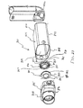
- FIGS. 1-11 show an aerosol medication delivery apparatus 10.
- the apparatus 10 comprises a pMDI canister-holding portion (or dispenser) 22 coupled to a chamber housing portion 24.
- the delivery apparatus 10 together with a pMDI canister 30 form an aerosol therapy system 12.
- the canister-holding portion 22 has a generally rectangular cross-sectional shape that defines a receiving area or receptacle 28 for receipt therein of the pMDI canister 30.
- the receiving area 28 is suited for conventional pMDI canisters of well-known construction.
- the pMDI canister 30 contains a medication suspension or solution under pressure. In the present embodiment, an HFA propelled medication suspension or solution formulation is used. In one embodiment, the liquid medication is flunisolide. Other propellants and other medications may also be used.
- the pMDI canister 30 has a stem 32 that permits a portion of the medication suspension or solution to be discharged therefrom upon application of a force on the stem 32.
- the canister stem 32 is positioned in a vertical channel or well 34 formed in the bottom of the canister-holding portion 22.
- ambient air can pass into the chamber via a passageway 33.
- a horizontal passage 35 communicates with the vertical channel 34.
- the horizontal passage 35 leads to a discharge orifice 36 located opposite from the vertical channel 34.
- the discharge orifice 36 forms the passage by which medication particles from the pMDI canister 30 can exit the canister holding portion 22 and enter into the chamber housing portion 24.
- the chamber housing 24 has an input end 46 and an output end 48 that define the ends of an interior space 39.
- the chamber housing portion 24 is formed of two parts: a main housing portion 43 and a downstream portion 45.
- the main housing portion 43 and the downstream portion 45 together define the interior space 39 of the chamber housing portion 24.
- the downstream portion 45 has retaining fingers 47 that engage in slots 49 on each side of the main housing portion 43. In the embodiment shown, the main housing portion 43 and the downstream portion 45 easily snap together and can be easily disconnected for cleaning.
- the main housing portion 43 has a curved cross section.
- the curved cross-section has a complex geometry formed of a plurality of radii to form a convenient, easy-to-use shape.
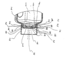
- a containment baffle 51 is located in the downstream portion 45 at the outlet of the chamber housing 24.
- the containment baffle 51 is located centrally and forms a distal wall 53 of the downstream portion 45.
- the containment baffle 51 is positioned so as to partially block the output end 48.
- the containment baffle 51 reduces the velocity or flow rate or both of the aerosol medication particles on axis 42 of the chamber housing 24.
- a mouthpiece 55 is located on the outside of the downstream portion 45 and includes the containment baffle 51 at an outlet end thereof.
- the containment baffle 51 has a concave-shaped center portion 62.
- the perimeter of the concave-shaped center portion 62 of the containment baffle 51 has generally straight vertical sides 57A and 57B, a curved top side 57C. and a curved bottom side 57D.
- the perimeter of the concave-shaped center portion 62 of the containment baffle 51 conforms generally in shape to the cross-sectional shape of the mouthpiece 55.
- the concave-shaped center portion 62 of the containment baffle 51 is aligned with a central axis 42 of the chamber housing 24 and is directly in line with the discharge orifice 36.
- Aerosol medication particles that have a flow path away from the axis of symmetry 42 tend to have a velocity that is lower than that of particles near to the axis of symmetry.
- the center portion 62 of the containment baffle 51 reduces the forward, on-axis velocity and simultaneously acts as an impaction surface for on-axis projectile aerosol medication particles.
- the center portion 62 allows slower moving aerosol medication particles to migrate towards the sides 52 of the chamber housing 24.
- the forward velocity of the aerosol medication particles away from the axis 42 along the chamber length is also reduced by the outer portion 66 of the containment baffle 51 that is concentric with the concave shaped center portion 62.
- the inhalation opening area 70 is Positioned between the center and outer portions 62 and 66 is an inhalation opening area 70.
- the inhalation opening area 70 is defined by four openings 70A-70D.
- the openings are arcuate in shape and conform to the periphery of the central portion 62.
- Each of the openings 70 has a length of approximately 9 mm and a width of approximately 2 mm. The size, shape and number of openings may vary depending on the medication suspension or solution formulation and/or propellant used.
- the aerosol delivery apparatus 10 includes a cap 74 which can be placed over the mouthpiece 55 to prevent contaminants from entering the interior space 39.
- the cap 74 serves to protect the mouthpiece 55 and keep it relatively clean.
- the canister-holding portion 22 and chamber housing 24 are arranged as shown in FIG. 1.
- the cap 74 is removed and the pMDI canister 30 is located in the receiving area 28 with the stem 32 inserted into the channel 34 formed in the bottom of the receiving area 28 as shown in FIG. 6.
- the apparatus 10 receives the pMDI canister 30 which is operated conventionally (i.e. by pressing down on the pMDI canister 30 which is located stem-side-down in the receiving area 28).
- the medication suspension or solution formulation in the pMDI canister 30 is discharged out of an opening 33 at the tip of the stem 32.
- the propellant and suspending liquid or solvent evaporate and the medication particles are discharged in aerosol form into the surrounding environment inside the chamber volume 39.
- the medication particles in the aerosol plume may have an average speed, size distribution and/or flow rate that may not be ideal for direct inhalation by a patient.
- the proportion of larger non-respirable particles available on inhalation is minimized and the dose of respirable particles is optimized.
- the aerosol medication particles are withdrawn therefrom by having the patient, whose mouth is around the mouthpiece 55, inhale through the inhalation opening area 70. The aerosol medication particles will then flow through the inhalation opening area 70 and into the patient's mouth.
- a further feature of the aerosol medication apparatus 10 is that it can be retracted for convenient storage and portability.
- the chamber housing 24 is coupled to the canister-holding portion 22 via a coupling mechanism 94 as shown in FIG. 11.
- the coupling mechanism 94 permits the aerosol medication delivery apparatus 10 to be compactly stored by pivoting the canister-holding portion 22 from the position of FIGS. 1-4 to a horizontal position and then pushing the canister-holding portion 22 so that it translationally moves into the chamber housing 24 as shown in FIG. 10.
- the coupling mechanism 94 includes a pair of slots 96 formed in the chamber housing 24, wherein each slot 96 has an open end 98 and a closed end 100.
- the canister-holding portion 22 has a pair of pegs 102, attached thereto.
- the interior portion of the chamber housing 24 has multiple parallel tracks 104 (shown in FIG. 10) which guide the canister-holding portion 22 into the chamber housing 24.
- a retaining structure (not shown) may be formed inside the upstream portion of the chamber housing 24. The retaining structure includes slots to receive the pegs 102 to guide the canister-holding portion 22 into the chamber housing 24.
- a top end 109 of the canister-holding portion 22 is first inserted into the output end 48 of the chamber housing 24 and translationally moved towards and past the input end 46 so that the pegs 102 are inserted into the open ends 98 of the corresponding slots 96. Each of the pegs 102 can then translationally move within its respective slot 96 to the closed end 100 thereof.
- the canister-holding portion 22 is telescopically received within the chamber housing 24 during translational movement and is able to move from the retracted position of FIG. 10 to an extended position.
- both pegs 102 contact the closed ends 100 of their corresponding slots 96 and the canister-holding portion 22 is then allowed to pivot to the position of FIG. 4 so that the patient can use the apparatus 10.
- the end of the canister-holding portion 22 is curved so as to allow it to pivot relative to the chamber housing 24.
- a plurality of ribs 77 may be located along the front and rear sides of the canister-holding portion 22 close to the top edge 109 thereof. These ribs 77 remain exposed when the canister-holding portion 22 is retracted into the chamber portion 24 so that the patient can use these ribs to help grip the end of the canister-holding portion 22 in order to withdraw it from the chamber portion 24. After use by the patient, the cap 74 can be placed back over the mouthpiece 55.
- the end result of combining the specified inhalation opening area 70, the chamber housing 24, and the containment baffle 51 is to administer a controllable and desired respirable dose of aerosol medication to a patient for inhalation into the lungs.
- the disclosed embodiment provides advantages over prior devices in that it incorporates an integrated actuator and is easier to use and is easier to store and carry given its smaller size.
- the containment baffle 51 An advantageous feature of the disclosed device is provided by the containment baffle 51.
- the velocity of the aerosol medication particles nearest the axis of symmetry 42 will typically be greater than that of aerosol medication particles that are located further from the axis 42.
- the velocity of the aerosol medication particles near the axis 42 may be so large as to reduce the effectiveness of delivering the medication to the patient because it will cause a significant portion of the aerosol medication particles to impact on the oropharyngeal region and upper airway where they have no therapeutic value and, in the case of medication such as corticosteroids, may give rise to adverse side-effects.
- the containment baffle 51 overcomes this potential problem by isolating the patient's mouth from the location at which the greatest risk of high velocity impaction may occur.
- the containment baffle provides this solution in a manner that is relatively inexpensive and easy to manufacture.
- the disclosed aerosol medication delivery apparatus optimizes the deposition of respirable aerosol medication particles in a patient's lungs to provide a desired therapeutic effect.
- the aerosol medication delivery apparatus also reduces the importance of coordination between the actuation and inhalation maneuvers and reduces or eliminates possible side-effects caused by aerosol medication formulations consisting of corticosteroids.
- the aerosol medication delivery apparatus also reduces or eliminates the unpleasant taste associated with aerosol medication formulations such as flunisolide and allows for convenient portability and quick use.
- the present device provides a particular advantage.
- the respirable dosage of flunisolide delivered to the patient can be controlled in a manner to closely conform to the dosage of flunisolide that had been delivered using conventional prior art systems that used prior propellants, such as CFC. In this manner, the dosage of flunisolide can be consistently maintained, thereby benefiting administration of such medication to patients.
- the shape, size, and number of openings in the inhalation opening area may vary in order to ensure the administration of a desired respirable dose of a specific pMDI formulation.
- the on-axis aerosol medication particles which are generally non-respirable and have a higher inertia than the respirable particles, collide with the interior center portion of the containment baffle resulting in a reduction in the number of larger (non-respirable) aerosol medication particles, and the division of larger (non-respirable) aerosol medication particles into smaller respirable particles.
- the containment baffle By sealing off (except for the inhalation opening area) the output end of the chamber, the containment baffle contributes to maintaining a high pressure zone in the chamber which allows for the deflection of most slower moving respirable aerosol medication particles away from the containment baffle and into the chamber for containment until inhaled by the patient through the inhalation opening area.
- the containment of the respirable aerosol medication particles in the chamber provides the patient with more time to inhale the aerosol medication particles and, therefore, reduces the importance of exact coordination between the discharge maneuver and inhalation.
- the canister-holding portion 22 is approximately 7.5 cm in height and is approximately 2.5 by 2.5 cm in cross section.
- the chamber housing 24 is approximately 8 cm in length and has an oval-shaped cross section with dimensions of approximately 49 mm by 33 mm.
- the mouthpiece 55 is approximately 1.5 cm in length.
- the canister-holding portion, the chamber housing, and the end cap are formed of a suitable hard, durable plastic, such as polypropylene.
- the discharge orifice 36 has a diameter of approximately 0.011 inches.
- the containment baffle 51 has a width of approximately 27 mm and a height of approximately 15 mm at the center and 5 mm at the side edges..
- the pMDI canister contains a 0.06% w/v to 0.24% w/v mixture of liquid medication, such as flunisolide in ethanolic solution and HFA as a propellant.
- the pMDI canister may contain a formulation of medication that uses CFC as a propellant. It is understood that the pMDI canister 30 can also contain other liquids and other mixtures,
- FIGS. 12 and 13 another aerosol delivery apparatus 110 is shown.
- This device is similar to the device shown in FIGS. 1-11 and like components are labeled with the same numerals.
- the containment baffle 151 is located at an upstream end of the passageway defined in the mouthpiece 55.
- the containment baffle 151 in this device is convex in shape and diverts flow around an on-axis trajectory.
- a chamber housing 124 has four squared-off sides 125, 126, 127, and 128. The squared-off sides may facilitate gripping of the device.
- a containment baffle 251 has a screen-like structure forming a plurality of openings defined between a crisscrossed mesh 252.
- the surface area provided by the mesh 252, combined with the relatively small areas of the openings, serves to prevent aerosol particles having a high velocity from passing to the patient.
- a containment baffle 351 has a plurality of small circular openings formed around a periphery of a solid central portion 362.
- the form of FIG. 15 provides a surface area 362, combined with the relatively small openings, serves to prevent aerosol particles having a high velocity from passing to the patient.
- FIG. 15 provides a surface area 362, combined with the relatively small openings, serves to prevent aerosol particles having a high velocity from passing to the patient.
- a containment baffle 451 has four relatively large openings formed around the periphery a solid dish-shaped central portion 462.
- the dish-shaped central portion 462 is connected to the remainder of the chamber body by one or more ribs 463.
- the form embodiment of FIG. 16 provides a surface area 462, that serves to prevent aerosol particles having a high velocity from passing to the patient.
- FIGS. 17 and 18 there is shown an alternate form 512 of an aerosol delivery apparatus.
- the device of FIGS. 17 and 18 includes an aerosol delivery apparatus 510.
- the apparatus 510 includes a chamber housing 524 which defines an interior space 539.
- the apparatus 510 does not include an integrated canister-holding portion. Instead, the chamber housing 524 has a backpiece 527.
- the backpiece 527 is made of an elastomeric material and is fitted over the upstream end of the chamber housing 524.
- the backpiece 527 has an opening 529 located centrally therein. The opening 529 is sized to receive the mouthpiece end of a separate pMDI actuator boot.
- the opening 529 is sized so that the mouthpiece of the pMDI actuator boot fits snugly into the opening 529. Because the backpiece 527 is formed of an elastomeric material, it is resilient and the opening 529 in the backpiece can be stretched, thereby enabling it accommodate actuator boot mouthpieces of various sizes and shapes.
- the backpiece 527 may be similar to the backpiece described in U.S. Pat. No. 4,470,412 or in U.S. Pat. No. 5,848,588.
- a mouthpiece 555 Located at a downstream end of the chamber housing 524 is a mouthpiece 555. Also located at the downstream end of the chamber housing 524 is a containment baffle 551.
- the containment baffle 551 may be similar to the containment baffle 51 in the above described device Located around the periphery of the containment baffle center portion 562 is an inhalation opening area 570.
- the inhalation opening area 570 includes four arcuate shaped openings.
- the containment baffle 551 is located at the downstream end of the mouthpiece 555, although in alternative devices the containment baffle may be located at the upstream end of the mouthpiece or anywhere along the length of the mouthpiece.
- the patient inserts the actuator boot mouthpiece into the opening 529 and inserts the pMDI canister into the actuator boot
- the patient inhales the aerosol from the interior space 539 via the mouthpiece 555 of the apparatus 510.
- FIGS. 19 and 20 Another aerosol medication delivery apparatus is shown in FIGS. 19 and 20.
- An aerosol delivery apparatus 610 includes a chamber housing 624 defining an interior space 639.
- the apparatus 610 also includes an elastomeric backpiece 627 which may be similar to the backpiece in the device shown in FIGS. 17 and 18.
- the apparatus 610 includes a containment baffle 651.
- the containment baffle 651 is located at the downstream end of the chamber housing 624 just upstream of the mouthpiece 655.
- the containment baffle 651 includes an inhalation opening area 670 located around the periphery of the containment baffle 651.
- the containment baffle 651 may be formed of a single piece of material with the chamber housing 624.
- the mouthpiece 655 may be formed of a separate piece of material that is coupled to the downstream end of the chamber housing 624.
- the device of FIGS. 19 and 20 may be used in a similar manner as the device of FIGS. 17 and 18.
- FIGS. 21 and 22 Still another aerosol medication delivery apparatus is shown in FIGS. 21 and 22.
- This aerosol delivery apparatus is particularly suited for use by a mechanically ventilated patient (i.e. a patient using a ventilator).
- an aerosol delivery apparatus 710 includes components that are similar to the previous devices, in particular the device of FIGS. 17 and 18.
- a chamber housing 724 defines an interior space 739.
- the apparatus 710 is intended to be positioned in a ventilator circuit, in particular in the air passageway that provides inspiratory air flow from a ventilator to the patient.
- the chamber housing 724 includes a first opening 727 located in a first tubular extension 728 extending from the upstream end 746 of the chamber housing 724 and a second opening 755 located in a second tubular extension 756 that extends from the downstream end 748 of the chamber housing 724.
- the first opening 727 connects to tubing 731 that leads to the ventilator (not shown) and the second opening 755 leads to tubing, a mask, a mouthpiece, or other suitable means (not shown) of providing air from the ventilator to the patient.
- Located at the upstream end of the chamber 724 is a receptacle 722.
- a well 734 adapted to receive the stem of a pMDI canister.
- the well 734 extends into a rib 735 that extends across the entrance into the interior space 739 of the chamber housing 724.
- the rib 735 may be located at or along the extension 728.
- the rib 735 includes a discharge opening 736 that communicates with the well 734.
- the discharge opening 736 is oriented toward the interior space 739.
- the receptacle 722, the rib 735, and the discharge opening 736 are integrated with the chamber housing 724 forming part of the aerosol delivery apparatus 710, (i.e. the receptacle and chamber housing form an integrated unit).
- the receptacle 722, the rib 735, and the discharge opening 736 are formed of the same piece of material as the chamber housing 724, or alternatively, they may be formed of separate pieces. Further disclosure regarding an integrated chamber housing and canister receptacle is included in U.S. Pat. No. 5,012,804.
- the containment baffle 751 may be located at the downstream end of the chamber housing 724 or along the extension 756.
- the containment baffle 751 includes an inhalation opening area 770 located around the periphery of the containment baffle 751.
- FIGS. 21 and 22 may be used in a similar manner as the device disclosed in U.S. Pat. No. 5,012,804.
- the apparatus 710 may be positioned in the inspiratory flow path from the ventilator to the patient when the patient is initially placed on the ventilator. The apparatus 710 is then left in place until needed. Alternatively, the apparatus 710 may be positioned in the inspiratory flow path of the ventilator circuit just prior to when a dose of aerosol medication is to be delivered to a ventilated patient.
- a pMDI canister is positioned in the receptacle 722 and actuated. The medication from the pMDI canister is conveyed with the inspiratory flow from the ventilator to the patient.
- the containment baffle 751 reduces on-axis non-respirable particles.
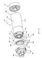
- FIGS. 23-25 Another aerosol medication delivery apparatus is shown in FIGS. 23-25.
- an aerosol delivery apparatus 810 includes components that are similar to the previous devices, in particular the devices shown in FIGS. 1-13.
- a chamber housing 824 has an input end 846 and an output end 848 that define the ends of an interior space 839.
- the chamber housing 824 is formed of a main housing portion 843 and a downstream portion 845 that together define the interior space 839 of the chamber housing 824.
- a mouthpiece 855 is located on the outside of the downstream portion 845. Formed in the interior of the mouthpiece is a sealing ledge 847. Exhalation ports 890 are disposed on the sides of the mouthpiece 855. The exhalation ports 890 are preferably generally rectangular shaped openings. Exhalation valves (not shown) could be built into the exhalation ports 890 in order to avoid the entrainment of any ambient air in the mouthpiece 855 before a valve 880 is opened.
- a baffle retainer member 856 is located in the mouthpiece 855 near where the mouthpiece 855 intersects the downstream portion 843.
- the baffle retainer member 856 includes a containment baffle 851, a retainer 853 and connecting members 857.
- the retainer 853 includes an inner wall 862, an outer wall 864 and a rear wall 866.
- the baffle retainer member 856 is attached to the mouthpiece 855 by snap fit to the mouthpiece.
- the baffle retainer member 856 can be attached to the mouthpiece 855 using an adhesive or by ultrasonic welding.
- the containment baffle 851 is located centrally and is operatively attached with the retainer 853 by the connecting members 857.
- the containment baffle 851 is positioned to partially block the output end 848.
- the containment baffle 851 is preferably dome shaped and has a concave surface and a convex surface.
- the containment baffle 851 is aligned with a central axis 842 of the housing 824 and is directly in line with a discharge orifice 836.
- the convex surface of the containment baffle faces downstream.
- the containment baffle 851 reduces the forward, on-axis velocity and simultaneously acts as an impaction surface for on-axis projectile aerosol medication particles.
- the inner wall 862, outer wall 864 and rear wall 866 of the retainer 853 join to form a channel 869.
- inhalation openings 870 are formed between the inner wall 862 and the outer perimeter of the containment baffle 851.
- the inhalation openings 870 are arcuate in shape and conform to the inner wall 862 and the outer perimeter of the containment baffle 851.
- a valve 880 is disposed in the mouthpiece and includes a valve member 885 and a valve seat 887.
- the valve 880 is positioned so that it can block the inhalation openings 870.
- the valve 880 is designed to allow medication to be withdrawn through the mouthpiece but prevents backflow into the chamber housing.
- the valve member 885 has a central open area 881, an inner portion 882 having an outer portion 884.
- the inner portion 882 has a sealing portion 879 that is formed along the inner periphery of the inner portion 882.
- the sealing portion 879 forms a continuous surface.
- An engaging member 883 is located on the outer portion 884 and is designed to be movable within the channel 869.
- the valve member 885 and the central open area 881 are preferably circular shaped. Alternatively they may be square shaped, rectangular shaped, triangular shaped, trapezoidal shaped or elliptical shaped.
- the valve member 885 is preferably made of a rigid material such as plastic or metal. In a preferred device, the valve member 885 is made of polypropylene or polyethylene. Alternatively, the valve member 885 could be made of a flexible material such as silicone, a thermoplastic elastomer, rubber or Ethylene-Propylene-Diene-Monomer (EPDM).
- EPDM E
- the valve seat 887 has a sealing surface 888 that is formed on the outer perimeter of the concave surface of the containment baffle.
- the sealing surface 888 is sized and shaped to meet with the sealing portion 887.
- the operation of the present device is similar to that of the embodiment shown in FIGS. 1-11.
- the patient presses down on the pMDI canister to cause a plume of medication to be discharged from the pMDI canister out of the mouthpiece of the actuator boot and into the interior space 839.
- the patient then inhales the aerosol from the interior space 839 via the mouthpiece 855 of the apparatus 810.
- the act of inhalation causes the valve 880 to move to an open or first position shown in FIG. 24.
- the valve member 885 moves downstream away from the valve seat 887 and a gap 892 is created between the sealing surface 888 and the sealing portion 879.
- the outer portion 884 is positioned adjacent the sealing ledge 847.
- the engaging member 883 is located at the opening of the channel 869.
- the valve 880 allows aerosol from the interior space to flow through the inhalation openings 870, through the gap, then through the central open area 881, then through the mouthpiece 855 to the patient.
- the engaging member 883 covers exhalation ports 890.
- the valve member 885 moves downstream and blocks the exhalation ports 890.
- the act of exhalation causes the valve 880 to move to a closed or second position shown in FIG. 25.
- the inner portion 882 is located so that it preferably completely covers the inhalation openings 870 and the sealing portion 579 mates with the sealing surface 888 so that it is disposed adjacent the sealing surface 888.
- the engaging member 883 is substantially disposed within the channel 869.
- the valve 880 prevents exhaled air and aerosol from flowing back into the chamber 824 and instead directs this exhaled air and aerosol to flow through the exhalation ports 890.
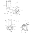
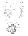
- An aerosol delivery apparatus 910 includes a chamber housing 924 having an input end 946 and an output end 948 defining ends of an interior space 939.
- the chamber housing 924 is formed of a main housing portion 943 and a downstream portion 945 that together define the interior space 939 of the chamber housing 924.
- the apparatus 910 also includes an elastomeric backpiece 927 which may be similar to the backpieces 527, 627 in the embodiments shown in FIGS. 17 and 19.
- the output end of the chamber housing 924 is shaped to receive the downstream portion 945 and includes locking tabs 990 and a protrusion 971, the protrusion 971 is preferably annular in shape.
- the locking tabs 990 are spaced apart around the outside of the output end 948.
- the downstream portion 943 includes a mouthpiece 955.
- the downstream portion 943 includes apertures 980, a sealing ledge 982, retaining ribs 984 and gaps 986 formed between the retaining ribs 984.
- the downstream portion 943 is connected to the output end 948 of the chamber housing 924 by placing the apertures 980 over the locking tabs 990.
- the retaining ribs 984 are spaced apart from an inner surface 985 of the downstream portion 945.
- the sealing ledge 982 is preferably circular shaped.
- a containment baffle 951 may be formed of a single piece of material with the chamber housing 924, and located near the output end 948.
- the containment baffle includes connecting members 969 that lead from the outer periphery of the containment baffle 951 to the inside of the chamber housing 924.
- Inhalation openings 970 are formed between the outer periphery of the containment baffle 951 and the chamber housing 924 and are separated by the connecting members 969.
- the inhalation openings 970 are arcuate in shape and conform to the outer perimeter of the containment baffle 951.
- the containment baffle 951 is dome shaped and has a concave surface 953 and a convex surface 956. The convex surface 956 of the dome points towards the input end 946 of the chamber 924.
- valve 960 having a valve member 962 and a valve seat 964 is shown.
- the valve seat 964 has a sealing surface 966 that is preferably formed on the outer perimeter of the downstream side of the containment baffle 951.
- the valve seat 964 conforms to the shape of the downstream portion of the containment baffle 951.
- the valve seat 964 is generally circular in shape.
- a valve member 962 includes a central open area 961, an inner portion 963, an outer portion 965 and an outer wall 968.
- the inner portion 963 is sized and shaped to cover the inhalation openings 970.
- a sealing portion 967 is located toward the interior of the inner portion 963. Referring to FIG. 30, the sealing portion 967 is shaped to mate with the sealing surface 966. The sealing portion 967 forms a continuous surface.
- the outer wall 968 is shaped to mate with the protrusion 971.
- the central open area 961, the inner portion 963 and the outer portion 965 are circular in shape.
- the inner portion 963, the outer portion 965 and the central open area 961 may be shaped differently, such as square shaped, rectangular shaped, elliptical shaped, circular shaped, trapezoidal shaped, triangular shaped or oblong shaped.
- the outer wall 968 is preferably shaped to conform with the protrusion 971. In the embodiment shown, the outer wall 968 is annular shaped.
- the valve member 962 is partially dome shaped in cross section.
- the valve member 962 is preferably made of plastic such as silicone or from a thermoplastic elastomer. Alternatively, the valve may be made of rubber or EPDM.
- the apparatus 910 is shown as assembled prior to inhalation by the patient.
- the valve member 962 is adjacent with the output end 948 of the chamber housing 924.
- the inner portion 963 covers the inhalation openings 970.
- the sealing portion 967 of the inner portion 963 of the valve member 962 mates with the sealing surface 966 of the containment baffle 951.
- the retaining ribs 984 of the mouthpiece 955 press the inner portion 963 against the output end 948 of the chamber housing 951 thereby generally holding the valve member 962 in place.
- the outer portion 965 is preferably located in a peripheral opening formed in between the sealing ledge 982 and the chamber housing 924.
- the operation of this embodiment is similar to the operation of the device of FIGS. 17 and 18; the patient presses down on the pMDI canister to cause a plume of aerosol medication to be discharged from the stem of the pMDI canister out of the mouthpiece of the actuator boot and into the interior space 939. The patient inhales the aerosol from the interior space 939 via the mouthpiece 955 of the apparatus 910.
- inhalation by the patient causes the sealing portion 967 to lift off of the sealing surface 966. This creates a gap 977 between the sealing portion 967 and the sealing surface 966.
- the gap 977 is uniform in size.
- the aerosol medication travels through the gap 977 and into the mouthpiece 955 where it may be inhaled by the patient.
- the patient may then exhale into the mouthpiece 955. Exhalation by the patient, results in air travelling through the mouthpiece 955. This air then passes through the openings in between the retaining ribs 984. Next the force of the exhaled air causes the outer portion 965 of the valve member 962 to move away from the annular sealing ledge 982 in a direction towards the chamber housing 924. As a result a passageway is created between the outer portion 965 and the annular sealing ledge 982 through which the exhaled air passes out to the atmosphere.
- An arrow 983 schematically illustrates a possible pathway of the exhaled air.
- FIGS. 26-32 An advantageous feature of the embodiment disclosed in FIGS. 26-32 is provided by the partial domed cross sectional shape of the valve member 962.
- This shape provides for a secure seal between the sealing portion 967 and the sealing surface 966.
- the partial domed cross sectional shape of the inner portion 963 also causes the sealing portion 967 to spring back against the sealing surface after the completion of inhalation by the patient, thereby ensuring the integrity of the seal for the next use of the apparatus.
- a further advantage is provided by the outer portion 965 moving against the sealing ledge 982 during inhalation. This prevents ambient air from leaking into the mouthpiece 955 during inhalation. As a result a lower flow rate of inhalation is required to open the valve to allow the aerosol medication to exit the chamber thereby making it easier for users that have low inhalation flow rates, such as young children and people of old age to open the valve so that they may inhale the medication.
- FIGS. 33-36 Another embodiment of the aerosol medication delivery apparatus is shown in FIGS. 33-36.
- An aerosol delivery apparatus 1000 includes a chamber housing 1024 having an input end 1046 and an output end 1048.
- the apparatus also includes an elastomeric backpiece which may be similar to the backpiece in the device shown in FIGS. 17 and 18.
- the chamber housing 1024 has a connecting portion 1025 formed near the output end 1048.
- a locking ridge 1056 is formed at the downstream end of the connecting portion 1025.
- the locking ridge 1056 is preferably annular in shape.
- the diameter of the chamber housing gradually increases from the input end 1046 to the output end 1048.
- the apparatus 1000 includes a baffle member 1050.
- the baffle member has a connecting edge 1053 that is generally sized and shaped to telescopically fit within the connecting portion 1025 to fix the baffle member 1050 to the chamber housing 1024.
- the apparatus 1000 has a downstream portion 1045.
- the downstream portion 1045 includes a mouthpiece 1055.
- the inside of the downstream portion 1045 includes an inner surface 1085, a recessed portion 1087 and exhalation ports 1089.
- Connecting clips 1057 are spaced apart along the inside surface of the mouthpiece.
- the recessed portion 1087 is preferably annular shaped.
- the downstream portion 1045 is disposed around the baffle member 1050 and fixed to the baffle member 1050 by the connecting clips 1057 which lock onto the locking ridge 1056.
- the baffle member 1050 includes a containment baffle 1051 at its downstream end.
- the containment baffle is similar to the containment baffle in the embodiment shown in FIGS. 26-32.
- a receiving member 1057 is formed at the downstream end of the baffle member 1050 and is positioned concentrically with respect to the containment baffle 1051.
- the receiving member 1057 is preferably annular in shape.
- a valve 1060 having a valve member 1062 and a valve seat 1064.
- the valve seat 1064 has a sealing surface 1066 that is preferably formed on the outer perimeter of the downstream side of the containment baffle 1051.
- the valve seat 1064 conforms to the shape of the downstream portion of the containment baffle 1051.
- the valve seat 1064 is generally circular in shape.
- the valve member 1062 includes a central open area 1061 an inner portion 1063, and an engaging member 1068.
- the engaging member 1068 has an input side 1071 and an output side 1073.
- the input side 1071 of the engaging member 1068 is concentrically positioned around the receiving member 1057.
- the output side 1073 of the engaging member 1068 is disposed within the recessed portion 1087.
- the inner portion 1063 is sized and shaped to cover inhalation openings 1070.
- a sealing portion 1067 is located near the interior of the inner portion 1063. Referring to FIG. 34, the sealing portion 1067 is shaped to mate with the sealing surface 1066. The sealing portion 1067 forms a continuous surface.
- the central open area 1061 and the inner portion 1063 are circular in shape. Alternatively, they may be square shaped, rectangular shaped, elliptical shaped, circular shaped, trapezoidal shaped, triangular shaped or oblong shaped.
- the engaging member 1068 is annular shaped.
- the valve member 1062 is preferably made of plastic such as silicone or from a thermoplastic elastomer. Alternatively, the valve member 1062 may be made of rubber or EPDM.
- the operation of the present embodiment is generally the same as the embodiment shown in FIGS. 26-32.
- the primary difference is that when the patient exhales, the majority of the exhaled air exits through the exhalation ports 1089 formed on the downstream portion 1045.
- FIGS. 37 and 38 Still another embodiment of the aerosol medication delivery apparatus is shown in FIGS. 37 and 38.
- an aerosol medication delivery apparatus 1110 includes components that are similar to the previous embodiments, in particular the embodiments shown in FIGS. 26-32 and FIGS. 33-36.
- a chamber housing 1124 having an input end 1146 and an output end 1148 defines an interior space 1139.
- the chamber housing also includes locking tabs 1190.
- the downstream portion of the chamber housing 1124 has a mask 1155 that may be positioned over the patient's mouth and against part of a patient's face.
- the mask 1155 includes a gripping ring 1151 located inside the mask at the upstream end, a frustoconical section 1153 that is formed with the gripping ring 1151 and extends downstream, and an end portion 1154 that is located downstream of and formed with the frustoconical section 1153.
- the end portion 1154 is preferably circular in shape.
- a housing 1157 is formed on the top portion of the mask and an exhalation valve 1159 is formed in this housing 1157.
- the mask 1155 may be similar to the mask described in U.S. Patent No. 5,645,049.
- the apparatus includes an attachment member 1140.
- the attachment member 1140 includes a connecting portion 1142 that includes apertures 1144.
- the connecting portion 1142 is generally sized and shaped to be disposed over the output end 1148 of the chamber housing 1124.
- the attachment member 1140 is fixed to the chamber housing 1124 by placing the apertures 1144 over the locking tabs 1190.
- the attachment member 1140 has a mask retaining portion 1143 formed integral with and downstream of the connecting portion 1142.
- the mask retaining portion 1143 includes locking members 1146 that are spaced apart and protrude outward from the mask retaining portion 1143.
- the mask retaining portion 1143 is inserted within the mask 1155 so that the gripping ring 1151 cooperates with the locking members 1146 to securely fix the mask 1155 to the mask retaining portion 1143.
- a locking ring 1148 is formed in the inside of the mask retaining portion 1143.
- a sealing ledge 1147 is formed at the intersection of the connecting portion 1 142 and the mask retaining portion 1143.
- the connecting portion 1142 and the mask retaining portion 1143 are preferably annular shaped.
- the sealing ledge 1147 and the locking ring 1148 are preferably circular shaped. Referring to FIG. 37, as assembled, the attachment member 1140 is fixed to the chamber housing 1124 by disposing the apertures 1144 over the locking tabs 1190.
- a valve 1160 including a valve seat 1162 and a valve member 1164, similar to the valve 1160 in the embodiment shown in FIGS. 26-32 is disposed between the attachment member 1140 and the chamber housing 1124.
- the locking ring 1148 presses an inner portion 1166 of the valve against connecting members formed on the containment baffle 1151.
- FIGS. 37 and 38 may be used in a similar manner as the embodiment of FIGS. 26-32. One difference is that during exhalation, the exhaled air passes out to the atmosphere through the exhalation valve.
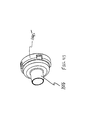
- FIGS. 39 and 40 Still another embodiment of the aerosol medication delivery apparatus is shown in FIGS. 39 and 40.
- the aerosol delivery apparatus 1210 includes components that are similar to the previous embodiments, in particular to the embodiment of FIGS. 33-36 and 37-38.
- the chamber housing 1224 includes an input end 1246 and an output end 1248 that define the interior space 1239.
- This embodiment includes a baffle member 1250, a valve 1260 and a mask 1255.
- the baffle member 1250 is similar to the baffle member shown in FIGS. 33-34.
- the mask 1255 is similar to the mask shown in FIG. 37.
- the valve 1260 is similar to the valve shown in FIGS. 33-36 and has a valve member 1262 that includes an engaging member 1268 having an inside side and an outside side.
- the apparatus also includes an attachment member 1240 similar to the attachment member in the embodiment shown in FIGS. 39 and 40. In this case, a connecting portion 1242 of the attachment member 1240 is sized and shaped to be disposable over the baffle member 1250.
- the connecting portion 1242 includes a first portion 1244 having a locking ring 1247 and a second annular portion 1246 formed downstream of the first portion 1244.
- a mask retaining portion 1243 of the connecting portion 1242 is located downstream of and formed with the annular portion 1244.
- the mask retaining portion 1243 is similar to the mask retaining portion of the embodiment shown in FIGS. 38 and 39.
- the mask retaining portion 1243 includes a recess 1249 that is preferably sized and shaped to receive the valve member 1262.
- the outside side of the valve member 1262 is disposed in the recess, where as the inside side of the valve member 1262 is concentrically positioned adjacent a receiving member 1257 formed on a downstream portion of the baffle member 1250.
- FIGS. 39 and 40 may be used in a similar manner as the embodiment of FIGS. 37 and 38.
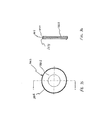
- valve member 1362 for use with the present invention is shown.
- the valve member 1362 is similar to the valve member in the embodiment shown in FIGS. 26-32.
- the primary difference is that the valve member 1362 has a central opening 1361 that is substantially smaller sized diameter.
- valve member 1462 for use with the present invention is shown.
- the valve member 1462 is similar to the valve member in the embodiment shown in FIGS. 26-32.
- the primary difference is that the valve member 1462 includes a center member 1463 disposed in the middle of the central open area 1461.
- the center member 1463 is cross shaped.
- FIG. 43 an alternative embodiment of a downstream portion 1545 for use with the present invention is shown.
- the downstream portion 1545 is similar to the downstream portion in the embodiment shown in FIGS. 26-32.
- the primary difference is that a mouthpiece 1555 on the downstream portion 1545 is circular in shape and designed to be used in conjunction with an endotracheal tube or other similar tube.
- valve member An advantageous feature of the embodiments disclosed in FIGS. 23-40 is provided by the valve member.
- the valve member tends to provide a more uniform flow than prior art valve members because the sealing portion which provides the gap upon inhalation is a continuous surface. Further, because the deflection of the valve member from the output end is minimal as compared to prior art devices, less dead space is required between the valve member and the end of the mouthpiece.
Abstract
Description
- This invention relates to a portable aerosol medication delivery apparatus and system for administering a desired respirable dosage of a medication in aerosol form to a patient's lungs by oral inhalation.
- The use of aerosol medication delivery systems to administer medication in aerosol form to a patient's lungs by inhalation is well known in the art.
- Conventional aerosol medication delivery systems include pressurized metered-dose inhalers (pMDIs). Conventional pMDIs typically have two components: a canister component in which the medication particles are stored under pressure in a suspension or solution form and a receptacle component used to hold and actuate the canister. The canister component typically includes a valved outlet from which the contents of the canister can be discharged. Aerosol medication is dispensed from the pMDI by applying a force on the canister component to push it into the receptacle component thereby opening the valved outlet and causing the medication particles to be conveyed from the valved outlet through the receptacle component and discharged from an outlet of the receptacle component. Upon discharge from the canister, the medication particles are "atomized" forming an aerosol. It is intended that the patient coordinate the discharge of aerosolized medication with his or her inhalation so that the medication particles are entrained in the patient's inspiratory flow and conveyed to the lungs. Typically, pMDIs have used propellants, such as chlorofluorocarbons (CFCs), to pressurize the contents of the canister and to propel the medication particles out of the outlet of the receptacle component.
- Although conventional pMDIs have been widely used to provide many patients with the benefits of aerosol medication, conventional pMDIs have certain drawbacks. For example, an objective of aerosol therapy has been the optimization of the mass percentage of the respirable dose of an aerosol medication in order to optimize deposition in a patient's lungs to achieve a full therapeutic effect with the least possible side-effects. Conventional pMDIs may not have always been able to meet this objective.
- One drawback associated with conventional pMDIs relates to the discharge velocity of the aerosol particles. Medication particles are stored under considerable pressure in the pMDI canister and as a consequence, their velocity may be high upon discharge.
- Among other things, the effect of high velocity contributes to a significant number of aerosol medication particles impacting and depositing in the patient's oropharynx and upper airway rather than continuing their pathway through the upper airway and into the lungs. Such impaction and deposition may result in a significant portion of the medication dose being systemically absorbed or ingested. As documented in the literature [J. L. Rau, "Respiratory Care Pharmacology", 4th ed. (1994, Mosby) at pp. 256-261; K. Meeran, A. Hattersley, J. Burrin, R. Shiner, K. Ibbertson K., "Oral and Inhaled Corticosteroids Reduce Bone Formation as Shown by Plasma Osteocalcin Levels", Am. J. Respir. Crit. Care Med 151:333-336], systemic absorption or ingestion of aerosol medication may cause a patient adverse side-effects, particularly when the aerosol medication is a corticosteroid. Some of these adverse side-effects include pharyngeal candidiasis, hoarseness, and adrenal suppression.
- The high velocity of the aerosol medication particles may also accentuate the difficulty of a significant number of patients, particularly the very young and elderly, to coordinate actuation of the pMDI with inhalation of the aerosol medication particles generated. Failure to coordinate the actuation and inhalation maneuvers and failure to inhale slowly, have been documented by the literature [S.P. Newman, "Aerosol Deposition Considerations in Inhalation Therapy" Chest /88 / 2 / August, 1985 / Supplement] as contributing to a significant reduction in the number of aerosol medication particles inspired and deposited in a patient's lungs. US-5385 140 discloses the features of the preamble of claim 1.
- Impaction and deposition of aerosol medication particles on a patient's oropharynx and upper airway may also contribute to an unpleasant taste in a patient's mouth, particularly with certain medication solution or suspension formulations such as flunisolide.
- In addition to high particle velocity, a significant number of large non-respirable medication particles may be produced upon discharge as a result of the medication suspension or solution formulation as well as the atomization process. As mentioned above, conventional pMDIs have used CFCs to propel the medication out of the pMDI actuator outlet. In view of environmental concerns with CFCs, there has been a growing interest in using non-CFC propellants, such as hydrofluoroalkanes (HFAs).
- An inhalation valve is often used in conjunction with an aerosol medication delivery apparatus to deliver a medication in an aerosol form to a user's respiratory tract. Typically, an inhalation valve is disposed at the output end of an aerosolization chamber and prevents aerosolized medication from leaving the chamber when the inhalation valve is in a closed position. When a patient inhales, the inhalation valve opens and allows the aerosolized medication to enter the patient's respiratory tract. The inhalation valve is usually designed to close upon exhalation by the patient.
- Prior art inhalation valves generally consist of a valve member and a valve seat. In some types of prior art valves, the outer perimeter of the valve member seals against the valve seat. In operation, the act of inhalation causes the outer perimeter of the valve to move away from the valve seat and allow aerosolized medication to flow through to the patient.
- In another type of prior art inhalation valve, the valve member includes one or more slits that define flaps on the valve member. Typically, the valve seat has a plurality of openings defined by what is known as a spider-like framework. In operation, when the patient inhales the flaps move away from the spider-like framework to allow aerosolized medication to pass through the openings to the patient. Upon exhalation, the flaps move against the framework to cover the openings. A number of advantageous improvements and modifications can be made to these prior designs.
- It is another object to provide a device which reduces the need for a patient to coordinate activation of a pMDI canister with inhalation.
- It is a further object to provide a device that reduces the delivery of non-respirable medication particles from a pMDI canister to a patient.
- It is yet another object to provide a device that reduces the impaction of medication particles on a patient's oropharynx and upper airway.
- It is still another object to provide a device for the delivery of aerosol medication from a pMDI canister that uses an HFA propellant instead of a CFC propellant.
- In order to address the above noted objectives, as well as other objectives, the present invention provides an improved aerosol medication delivery apparatus having the features as set out in claim 1.
- The invention provides the foregoing and other features, and the advantages of the invention will become further apparent from the following detailed description of the presently preferred embodiments, read in conjunction with the accompanying drawings. The detailed description and drawings are merely illustrative of the invention and do not limit the scope of the invention, which is defined by the appended claims and equivalents thereof
-
- FIG. 1 is a perspective view of an aerosol medication delivery system
- FIG. 2 is an exploded view of the aerosol medication delivery system of FIG. 1.
- FIG. 3 is a side view of the aerosol medication delivery system of FIG. 1.
- FIG. 4 is a side sectional view of the aerosol medication delivery system of FIG. 1.
- FIG. 5 is a front view of the canister-holding portion shown in FIG. 1.
- FIG. 6 is a sectional view of the canister-holding portion of FIG. 5 taken along
line 6―6'. - FIG. 7 is a side view of the downstream housing portion in FIG 1.
- FIG. 8 is an end view of the downstream housing portion shown in FIG. 7.
- FIG. 9 is a sectional view of the downstream housing portion shown in FIG. 8 taken along line 9―9'.
- FIG. 10 is a sectional view of the embodiment in FIG. I in a retracted position.
- FIG. 11 is an enlarged sectional view of an inside upstream portion of the chamber housing of FIG. I showing part of the coupling mechanism.
- FIG. 12 is a perspective view of an other aerosol medication delivery system
- FIG. 13 is an end view of the embodiment of FIG. 12.
- FIGS. 14-16 each show an end view of an alternative embodiment of the containment baffle shown in FIG. 8.
- FIG. 17 is a side sectional view of another alternative embodiment of the aerosol medication delivery apparatus of FIG. 1.
- FIG. 18 is a end view of the embodiment shown in FIG. 17
- FIG. 19 is a side sectional view of yet another alternative embodiment of the aerosol medication delivery apparatus of FIG. 1.
- FIG. 20 is an end view of the containment baffle of the embodiment of FIG. 19.
- FIG. 21 is a side sectional view of yet another alternative embodiment of the aerosol medication delivery apparatus of FIG. 1.
- FIG. 22 is an end view of the containment baffle of the embodiment of FIG. 21.
- FIG. 23 is an exploded perspective view of an alternative aerosol medication delivery system
- FIG. 24 is a sectional view of the embodiment of FIG. 23.
- FIG. 25 is a sectional view of the embodiment of FIG. 23.
- FIG. 26 is an exploded perspective view of yet another alternative embodiment of aerosol medication delivery apparatus of FIG. I.
- FIG. 27 is a front view of a valve member used in the embodiment shown in FIG. 26.
- FIG. 28 is a sectional view taken along line 28-28 of FIG. 27.
- FIG. 29 is a perspective view of a mouth piece used in the embodiment of the invention shown in FIG. 26.
- FIG. 30 is a side sectional view of the embodiment of FIG. 26.
- FIG. 31 is a side sectional view of the embodiment of FIG. 26 shown during inhalation by the patient.
- FIG. 32 is a side sectional view of the embodiment of FIG. 26 shown during exhalation by the patient.
- FIG. 33 is an exploded perspective view of yet another alternative embodiment of the aerosol medication delivery apparatus of FIG. 1.
- FIG. 34 is a side sectional view of the embodiment of FIG. 33.
- FIG. 35 is a front view of the valve used in the embodiment of FIG. 33.
- FIG. 36 is a side sectional view of the valve shown in FIG. 35.
- FIG. 37 is a side sectional view of another alternative embodiment of the aerosol medication delivery apparatus of FIG. 1.
- FIG. 38 is a perspective view of an attachment member used in the embodiment shown in FIG. 37.
- FIG. 39 is an exploded perspective view of yet another alternative embodiment of the aerosol medications of the apparatus of FIG. I.
- FIG. 40 is a side sectional view of the embodiment of FIG. 39.
- FIG. 41 shows an alternative embodiment of a valve member for use with the present invention.
- FIG. 42 shows another alternative embodiment of a valve member for use with the present invention.
- FIG. 43 shows an alternative embodiment of a mouth piece for use with the present invention.
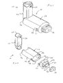
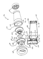
- FIGS. 1-11 show an aerosol
medication delivery apparatus 10. Theapparatus 10 comprises a pMDI canister-holding portion (or dispenser) 22 coupled to achamber housing portion 24. Thedelivery apparatus 10 together with apMDI canister 30 form anaerosol therapy system 12. - The canister-holding
portion 22 has a generally rectangular cross-sectional shape that defines a receiving area orreceptacle 28 for receipt therein of thepMDI canister 30. The receivingarea 28 is suited for conventional pMDI canisters of well-known construction. ThepMDI canister 30 contains a medication suspension or solution under pressure. In the present embodiment, an HFA propelled medication suspension or solution formulation is used. In one embodiment, the liquid medication is flunisolide. Other propellants and other medications may also be used. - Referring to FIG. 6, the
pMDI canister 30 has astem 32 that permits a portion of the medication suspension or solution to be discharged therefrom upon application of a force on thestem 32. When thepMDI canister 30 is located in the receivingarea 28 of the canister-holdingportion 22, thecanister stem 32 is positioned in a vertical channel or well 34 formed in the bottom of the canister-holdingportion 22. When thestem 32 of thecanister 30 is located in thevertical channel 34, ambient air can pass into the chamber via apassageway 33. Ahorizontal passage 35 communicates with thevertical channel 34. Thehorizontal passage 35 leads to adischarge orifice 36 located opposite from thevertical channel 34. - Referring to FIG. 6, the
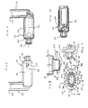
discharge orifice 36 forms the passage by which medication particles from thepMDI canister 30 can exit thecanister holding portion 22 and enter into thechamber housing portion 24. Thechamber housing 24 has aninput end 46 and anoutput end 48 that define the ends of aninterior space 39. - Referring to FIGS. 2 - 4, in a present device, the
chamber housing portion 24 is formed of two parts: amain housing portion 43 and adownstream portion 45. Themain housing portion 43 and thedownstream portion 45 together define theinterior space 39 of thechamber housing portion 24. Thedownstream portion 45 has retainingfingers 47 that engage inslots 49 on each side of themain housing portion 43. In the embodiment shown, themain housing portion 43 and thedownstream portion 45 easily snap together and can be easily disconnected for cleaning. - Referring to FIG. 2, the
main housing portion 43 has a curved cross section. In a present embodiment, the curved cross-section has a complex geometry formed of a plurality of radii to form a convenient, easy-to-use shape. - Referring to FIGS. 2 and 7-9, a
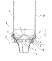
containment baffle 51 is located in thedownstream portion 45 at the outlet of thechamber housing 24. Thecontainment baffle 51 is located centrally and forms adistal wall 53 of thedownstream portion 45. Thecontainment baffle 51 is positioned so as to partially block theoutput end 48. Thecontainment baffle 51 reduces the velocity or flow rate or both of the aerosol medication particles onaxis 42 of thechamber housing 24. Amouthpiece 55 is located on the outside of thedownstream portion 45 and includes thecontainment baffle 51 at an outlet end thereof. - As shown in FIGS. 7-9, the
containment baffle 51 has a concave-shapedcenter portion 62. In the device shown, the perimeter of the concave-shapedcenter portion 62 of thecontainment baffle 51 has generally straightvertical sides 57A and 57B, a curved top side 57C. and a curved bottom side 57D. The perimeter of the concave-shapedcenter portion 62 of thecontainment baffle 51 conforms generally in shape to the cross-sectional shape of themouthpiece 55. The concave-shapedcenter portion 62 of thecontainment baffle 51 is aligned with acentral axis 42 of thechamber housing 24 and is directly in line with thedischarge orifice 36. Aerosol medication particles that have a flow path away from the axis ofsymmetry 42 tend to have a velocity that is lower than that of particles near to the axis of symmetry. Thecenter portion 62 of thecontainment baffle 51 reduces the forward, on-axis velocity and simultaneously acts as an impaction surface for on-axis projectile aerosol medication particles. At the same time thecenter portion 62 allows slower moving aerosol medication particles to migrate towards thesides 52 of thechamber housing 24. The forward velocity of the aerosol medication particles away from theaxis 42 along the chamber length is also reduced by theouter portion 66 of thecontainment baffle 51 that is concentric with the concave shapedcenter portion 62. - Positioned between the center and
outer portions central portion 62. Each of the openings 70 has a length of approximately 9 mm and a width of approximately 2 mm. The size, shape and number of openings may vary depending on the medication suspension or solution formulation and/or propellant used. - In a present device, the
aerosol delivery apparatus 10 includes acap 74 which can be placed over themouthpiece 55 to prevent contaminants from entering theinterior space 39. Thecap 74 serves to protect themouthpiece 55 and keep it relatively clean. - To use the
aerosol delivery apparatus 10 for delivery of an aerosol medication, the canister-holdingportion 22 andchamber housing 24 are arranged as shown in FIG. 1. Thecap 74 is removed and thepMDI canister 30 is located in the receivingarea 28 with thestem 32 inserted into thechannel 34 formed in the bottom of the receivingarea 28 as shown in FIG. 6. As mentioned above, theapparatus 10 receives thepMDI canister 30 which is operated conventionally (i.e. by pressing down on thepMDI canister 30 which is located stem-side-down in the receiving area 28). Upon depression of thestem 32, the medication suspension or solution formulation in thepMDI canister 30 is discharged out of anopening 33 at the tip of thestem 32. As the medication suspension or solution formulation flows through thehorizontal channel 35 and out of thedischarge orifice 36, the propellant and suspending liquid or solvent evaporate and the medication particles are discharged in aerosol form into the surrounding environment inside thechamber volume 39. Upon discharge from thepMDI canister 30, the medication particles in the aerosol plume may have an average speed, size distribution and/or flow rate that may not be ideal for direct inhalation by a patient. However, once the aerosol medication is inside thechamber volume 39, the proportion of larger non-respirable particles available on inhalation is minimized and the dose of respirable particles is optimized. The aerosol medication particles are withdrawn therefrom by having the patient, whose mouth is around themouthpiece 55, inhale through the inhalation opening area 70. The aerosol medication particles will then flow through the inhalation opening area 70 and into the patient's mouth. - A further feature of the
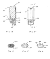
aerosol medication apparatus 10 is that it can be retracted for convenient storage and portability. For this purpose, thechamber housing 24 is coupled to the canister-holdingportion 22 via acoupling mechanism 94 as shown in FIG. 11. Thecoupling mechanism 94 permits the aerosolmedication delivery apparatus 10 to be compactly stored by pivoting the canister-holdingportion 22 from the position of FIGS. 1-4 to a horizontal position and then pushing the canister-holdingportion 22 so that it translationally moves into thechamber housing 24 as shown in FIG. 10. - Referring to FIG. 11, the pivoting and translational movement is accomplished by the structure of the
coupling mechanism 94. In particular, thecoupling mechanism 94 includes a pair ofslots 96 formed in thechamber housing 24, wherein eachslot 96 has anopen end 98 and aclosed end 100. As shown in FIG. 5, the canister-holdingportion 22 has a pair ofpegs 102, attached thereto. In addition, the interior portion of thechamber housing 24 has multiple parallel tracks 104 (shown in FIG. 10) which guide the canister-holdingportion 22 into thechamber housing 24. Alternatively, instead of parallel tracks a retaining structure (not shown) may be formed inside the upstream portion of thechamber housing 24. The retaining structure includes slots to receive thepegs 102 to guide the canister-holdingportion 22 into thechamber housing 24. - To connect the
chamber housing 24 and the canister-holdingportion 22 together, atop end 109 of the canister-holdingportion 22 is first inserted into theoutput end 48 of thechamber housing 24 and translationally moved towards and past theinput end 46 so that thepegs 102 are inserted into the open ends 98 of the correspondingslots 96. Each of thepegs 102 can then translationally move within itsrespective slot 96 to theclosed end 100 thereof. Thus, the canister-holdingportion 22 is telescopically received within thechamber housing 24 during translational movement and is able to move from the retracted position of FIG. 10 to an extended position. At the extended position, bothpegs 102 contact the closed ends 100 of theircorresponding slots 96 and the canister-holdingportion 22 is then allowed to pivot to the position of FIG. 4 so that the patient can use theapparatus 10. The end of the canister-holdingportion 22 is curved so as to allow it to pivot relative to thechamber housing 24. The foregoing coupling and retraction mechanism allow for easy use, transport, and lower manufacturing costs. - To facilitate handling by the patient, a plurality of
ribs 77 may be located along the front and rear sides of the canister-holdingportion 22 close to thetop edge 109 thereof. Theseribs 77 remain exposed when the canister-holdingportion 22 is retracted into thechamber portion 24 so that the patient can use these ribs to help grip the end of the canister-holdingportion 22 in order to withdraw it from thechamber portion 24. After use by the patient, thecap 74 can be placed back over themouthpiece 55. - With the device disclosed above, the end result of combining the specified inhalation opening area 70, the
chamber housing 24, and thecontainment baffle 51 is to administer a controllable and desired respirable dose of aerosol medication to a patient for inhalation into the lungs. Further, the disclosed embodiment provides advantages over prior devices in that it incorporates an integrated actuator and is easier to use and is easier to store and carry given its smaller size. - An advantageous feature of the disclosed device is provided by the
containment baffle 51. As mentioned above, the velocity of the aerosol medication particles nearest the axis ofsymmetry 42 will typically be greater than that of aerosol medication particles that are located further from theaxis 42. The velocity of the aerosol medication particles near theaxis 42 may be so large as to reduce the effectiveness of delivering the medication to the patient because it will cause a significant portion of the aerosol medication particles to impact on the oropharyngeal region and upper airway where they have no therapeutic value and, in the case of medication such as corticosteroids, may give rise to adverse side-effects.Thecontainment baffle 51 overcomes this potential problem by isolating the patient's mouth from the location at which the greatest risk of high velocity impaction may occur. The containment baffle provides this solution in a manner that is relatively inexpensive and easy to manufacture. - The disclosed aerosol medication delivery apparatus optimizes the deposition of respirable aerosol medication particles in a patient's lungs to provide a desired therapeutic effect. The aerosol medication delivery apparatus also reduces the importance of coordination between the actuation and inhalation maneuvers and reduces or eliminates possible side-effects caused by aerosol medication formulations consisting of corticosteroids. The aerosol medication delivery apparatus also reduces or eliminates the unpleasant taste associated with aerosol medication formulations such as flunisolide and allows for convenient portability and quick use.
- In the case of pMDIs that use HFA as a propellant for flunisolide, the present device provides a particular advantage. Through use of the present device, the respirable dosage of flunisolide delivered to the patient can be controlled in a manner to closely conform to the dosage of flunisolide that had been delivered using conventional prior art systems that used prior propellants, such as CFC. In this manner, the dosage of flunisolide can be consistently maintained, thereby benefiting administration of such medication to patients.
- The shape, size, and number of openings in the inhalation opening area may vary in order to ensure the administration of a desired respirable dose of a specific pMDI formulation. Upon discharge the on-axis aerosol medication particles, which are generally non-respirable and have a higher inertia than the respirable particles, collide with the interior center portion of the containment baffle resulting in a reduction in the number of larger (non-respirable) aerosol medication particles, and the division of larger (non-respirable) aerosol medication particles into smaller respirable particles.
- By sealing off (except for the inhalation opening area) the output end of the chamber, the containment baffle contributes to maintaining a high pressure zone in the chamber which allows for the deflection of most slower moving respirable aerosol medication particles away from the containment baffle and into the chamber for containment until inhaled by the patient through the inhalation opening area. The containment of the respirable aerosol medication particles in the chamber provides the patient with more time to inhale the aerosol medication particles and, therefore, reduces the importance of exact coordination between the discharge maneuver and inhalation.
- In one exemplary embodiment, shown in FIGS. 1-11, the canister-holding
portion 22 is approximately 7.5 cm in height and is approximately 2.5 by 2.5 cm in cross section. Thechamber housing 24 is approximately 8 cm in length and has an oval-shaped cross section with dimensions of approximately 49 mm by 33 mm. Themouthpiece 55 is approximately 1.5 cm in length. The canister-holding portion, the chamber housing, and the end cap are formed of a suitable hard, durable plastic, such as polypropylene. Thedischarge orifice 36 has a diameter of approximately 0.011 inches. In a present device, thecontainment baffle 51 has a width of approximately 27 mm and a height of approximately 15 mm at the center and 5 mm at the side edges.. - For purposes of this device, it is assumed that the pMDI canister contains a 0.06% w/v to 0.24% w/v mixture of liquid medication, such as flunisolide in ethanolic solution and HFA as a propellant. Alternatively, the pMDI canister may contain a formulation of medication that uses CFC as a propellant. It is understood that the
pMDI canister 30 can also contain other liquids and other mixtures, - Referring to FIGS. 12 and 13, another
aerosol delivery apparatus 110 is shown. This device is similar to the device shown in FIGS. 1-11 and like components are labeled with the same numerals. In the device of FIGS. 12 and 13, thecontainment baffle 151 is located at an upstream end of the passageway defined in themouthpiece 55. Thecontainment baffle 151 in this device is convex in shape and diverts flow around an on-axis trajectory. In the device of FIGS. 12 and 13, achamber housing 124 has four squared-offsides - Referring to FIGS. 14-16, there are depicted alternative forms of the containment baffle. In FIG. 14, a
containment baffle 251 has a screen-like structure forming a plurality of openings defined between acrisscrossed mesh 252. The surface area provided by themesh 252, combined with the relatively small areas of the openings, serves to prevent aerosol particles having a high velocity from passing to the patient. In FIG. 15, acontainment baffle 351 has a plurality of small circular openings formed around a periphery of a solidcentral portion 362. Like the previous forms, the form of FIG. 15 provides asurface area 362, combined with the relatively small openings, serves to prevent aerosol particles having a high velocity from passing to the patient. In FIG. 16, acontainment baffle 451 has four relatively large openings formed around the periphery a solid dish-shapedcentral portion 462. The dish-shapedcentral portion 462 is connected to the remainder of the chamber body by one ormore ribs 463. Like the previous forms, the form embodiment of FIG. 16 provides asurface area 462, that serves to prevent aerosol particles having a high velocity from passing to the patient. - Referring to FIGS. 17 and 18, there is shown an alternate form 512 of an aerosol delivery apparatus. The device of FIGS. 17 and 18 includes an
aerosol delivery apparatus 510. Theapparatus 510 includes achamber housing 524 which defines aninterior space 539. Theapparatus 510 does not include an integrated canister-holding portion. Instead, thechamber housing 524 has abackpiece 527. Thebackpiece 527 is made of an elastomeric material and is fitted over the upstream end of thechamber housing 524. Thebackpiece 527 has anopening 529 located centrally therein. Theopening 529 is sized to receive the mouthpiece end of a separate pMDI actuator boot. In a preferred device, theopening 529 is sized so that the mouthpiece of the pMDI actuator boot fits snugly into theopening 529. Because thebackpiece 527 is formed of an elastomeric material, it is resilient and theopening 529 in the backpiece can be stretched, thereby enabling it accommodate actuator boot mouthpieces of various sizes and shapes. Thebackpiece 527 may be similar to the backpiece described in U.S. Pat. No. 4,470,412 or in U.S. Pat. No. 5,848,588. - Located at a downstream end of the
chamber housing 524 is amouthpiece 555. Also located at the downstream end of thechamber housing 524 is acontainment baffle 551. Thecontainment baffle 551 may be similar to thecontainment baffle 51 in the above described device Located around the periphery of the containmentbaffle center portion 562 is aninhalation opening area 570. Theinhalation opening area 570 includes four arcuate shaped openings. In the embodiment of FIGS. 17 and 18, thecontainment baffle 551 is located at the downstream end of themouthpiece 555, although in alternative devices the containment baffle may be located at the upstream end of the mouthpiece or anywhere along the length of the mouthpiece. - With the embodiment of FIGS. 17 and 18, the patient inserts the actuator boot mouthpiece into the
opening 529 and inserts the pMDI canister into the actuator boot The patient presses down on the pMDI canister to cause a plume of aerosol medication to be discharged from the stem of the pMDI canister out of the mouthpiece of the actuator boot and into theinterior space 539. The patient inhales the aerosol from theinterior space 539 via themouthpiece 555 of theapparatus 510. - Another aerosol medication delivery apparatus is shown in FIGS. 19 and 20. An aerosol delivery apparatus 610 includes a
chamber housing 624 defining aninterior space 639. The apparatus 610 also includes anelastomeric backpiece 627 which may be similar to the backpiece in the device shown in FIGS. 17 and 18. The apparatus 610 includes acontainment baffle 651. Thecontainment baffle 651 is located at the downstream end of thechamber housing 624 just upstream of themouthpiece 655. Thecontainment baffle 651 includes aninhalation opening area 670 located around the periphery of thecontainment baffle 651. In the device of FIGS. 19 and 20, thecontainment baffle 651 may be formed of a single piece of material with thechamber housing 624. Themouthpiece 655 may be formed of a separate piece of material that is coupled to the downstream end of thechamber housing 624. The device of FIGS. 19 and 20 may be used in a similar manner as the device of FIGS. 17 and 18. - Still another aerosol medication delivery apparatus is shown in FIGS. 21 and 22. This aerosol delivery apparatus is particularly suited for use by a mechanically ventilated patient (i.e. a patient using a ventilator). In FIG. 21, an
aerosol delivery apparatus 710 includes components that are similar to the previous devices, in particular the device of FIGS. 17 and 18. Achamber housing 724 defines aninterior space 739. Theapparatus 710 is intended to be positioned in a ventilator circuit, in particular in the air passageway that provides inspiratory air flow from a ventilator to the patient. Thechamber housing 724 includes afirst opening 727 located in a firsttubular extension 728 extending from theupstream end 746 of thechamber housing 724 and asecond opening 755 located in a secondtubular extension 756 that extends from thedownstream end 748 of thechamber housing 724. Thefirst opening 727 connects totubing 731 that leads to the ventilator (not shown) and thesecond opening 755 leads to tubing, a mask, a mouthpiece, or other suitable means (not shown) of providing air from the ventilator to the patient. Located at the upstream end of thechamber 724 is areceptacle 722. At the bottom of thereceptacle 722 is a well 734 adapted to receive the stem of a pMDI canister. The well 734 extends into arib 735 that extends across the entrance into theinterior space 739 of thechamber housing 724. Therib 735 may be located at or along theextension 728. Therib 735 includes adischarge opening 736 that communicates with thewell 734. Thedischarge opening 736 is oriented toward theinterior space 739. Thereceptacle 722, therib 735, and thedischarge opening 736 are integrated with thechamber housing 724 forming part of theaerosol delivery apparatus 710, (i.e. the receptacle and chamber housing form an integrated unit). In one embodiment thereceptacle 722, therib 735, and thedischarge opening 736 are formed of the same piece of material as thechamber housing 724, or alternatively, they may be formed of separate pieces. Further disclosure regarding an integrated chamber housing and canister receptacle is included in U.S. Pat. No. 5,012,804. - Located at the
downstream end 748 of thechamber 724 is acontainment baffle 751. Thecontainment baffle 751 may be located at the downstream end of thechamber housing 724 or along theextension 756. Thecontainment baffle 751 includes aninhalation opening area 770 located around the periphery of thecontainment baffle 751. - The embodiment of FIGS. 21 and 22 may be used in a similar manner as the device disclosed in U.S. Pat. No. 5,012,804. The
apparatus 710 may be positioned in the inspiratory flow path from the ventilator to the patient when the patient is initially placed on the ventilator. Theapparatus 710 is then left in place until needed. Alternatively, theapparatus 710 may be positioned in the inspiratory flow path of the ventilator circuit just prior to when a dose of aerosol medication is to be delivered to a ventilated patient. A pMDI canister is positioned in thereceptacle 722 and actuated. The medication from the pMDI canister is conveyed with the inspiratory flow from the ventilator to the patient. As in the previously described embodiments, thecontainment baffle 751 reduces on-axis non-respirable particles. - Another aerosol medication delivery apparatus is shown in FIGS. 23-25. In FIG. 23, an
aerosol delivery apparatus 810 includes components that are similar to the previous devices, in particular the devices shown in FIGS. 1-13. Achamber housing 824 has an input end 846 and anoutput end 848 that define the ends of aninterior space 839. Thechamber housing 824 is formed of amain housing portion 843 and adownstream portion 845 that together define theinterior space 839 of thechamber housing 824. - A
mouthpiece 855 is located on the outside of thedownstream portion 845. Formed in the interior of the mouthpiece is a sealingledge 847.Exhalation ports 890 are disposed on the sides of themouthpiece 855. Theexhalation ports 890 are preferably generally rectangular shaped openings. Exhalation valves (not shown) could be built into theexhalation ports 890 in order to avoid the entrainment of any ambient air in themouthpiece 855 before avalve 880 is opened. - As shown in FIGS. 23-25, a
baffle retainer member 856 is located in themouthpiece 855 near where themouthpiece 855 intersects thedownstream portion 843. Thebaffle retainer member 856 includes acontainment baffle 851, aretainer 853 and connectingmembers 857. Theretainer 853 includes aninner wall 862, anouter wall 864 and arear wall 866. In a preferred embodiment, thebaffle retainer member 856 is attached to themouthpiece 855 by snap fit to the mouthpiece. Alternatively, thebaffle retainer member 856 can be attached to themouthpiece 855 using an adhesive or by ultrasonic welding. - Referring to FIG. 23, the
containment baffle 851 is located centrally and is operatively attached with theretainer 853 by the connectingmembers 857. Thecontainment baffle 851 is positioned to partially block theoutput end 848. As shown in FIG. 23, thecontainment baffle 851 is preferably dome shaped and has a concave surface and a convex surface. Like the embodiment shown in FIGS. 1-11, thecontainment baffle 851 is aligned with acentral axis 842 of thehousing 824 and is directly in line with adischarge orifice 836. The convex surface of the containment baffle faces downstream. Thecontainment baffle 851 reduces the forward, on-axis velocity and simultaneously acts as an impaction surface for on-axis projectile aerosol medication particles. - As shown in FIG. 24-25, the
inner wall 862,outer wall 864 andrear wall 866 of theretainer 853 join to form achannel 869. In addition,inhalation openings 870 are formed between theinner wall 862 and the outer perimeter of thecontainment baffle 851. Theinhalation openings 870 are arcuate in shape and conform to theinner wall 862 and the outer perimeter of thecontainment baffle 851. - Referring to FIGS. 23-25 a
valve 880 is disposed in the mouthpiece and includes avalve member 885 and avalve seat 887. Thevalve 880 is positioned so that it can block theinhalation openings 870. Thevalve 880 is designed to allow medication to be withdrawn through the mouthpiece but prevents backflow into the chamber housing. - In the device shown, the
valve member 885 has a centralopen area 881, aninner portion 882 having anouter portion 884. Theinner portion 882 has a sealingportion 879 that is formed along the inner periphery of theinner portion 882. The sealingportion 879 forms a continuous surface. An engagingmember 883 is located on theouter portion 884 and is designed to be movable within thechannel 869. Thevalve member 885 and the centralopen area 881 are preferably circular shaped. Alternatively they may be square shaped, rectangular shaped, triangular shaped, trapezoidal shaped or elliptical shaped. Thevalve member 885 is preferably made of a rigid material such as plastic or metal. In a preferred device, thevalve member 885 is made of polypropylene or polyethylene. Alternatively, thevalve member 885 could be made of a flexible material such as silicone, a thermoplastic elastomer, rubber or Ethylene-Propylene-Diene-Monomer (EPDM). - The
valve seat 887 has a sealingsurface 888 that is formed on the outer perimeter of the concave surface of the containment baffle. The sealingsurface 888 is sized and shaped to meet with the sealingportion 887. - The operation of the present device is similar to that of the embodiment shown in FIGS. 1-11. The patient presses down on the pMDI canister to cause a plume of medication to be discharged from the pMDI canister out of the mouthpiece of the actuator boot and into the
interior space 839. The patient then inhales the aerosol from theinterior space 839 via themouthpiece 855 of theapparatus 810. - The act of inhalation causes the
valve 880 to move to an open or first position shown in FIG. 24. When the patient inhales thevalve member 885 moves downstream away from thevalve seat 887 and agap 892 is created between the sealingsurface 888 and the sealingportion 879. In this first position, theouter portion 884 is positioned adjacent the sealingledge 847. The engagingmember 883 is located at the opening of thechannel 869. In this first position, the valve 880allows aerosol from the interior space to flow through theinhalation openings 870, through the gap, then through the centralopen area 881, then through themouthpiece 855 to the patient. Also in this first position the engagingmember 883 coversexhalation ports 890. Thus, during inhalation thevalve member 885 moves downstream and blocks theexhalation ports 890. - The act of exhalation causes the
valve 880 to move to a closed or second position shown in FIG. 25. In this second position, theinner portion 882 is located so that it preferably completely covers theinhalation openings 870 and the sealing portion 579 mates with the sealingsurface 888 so that it is disposed adjacent the sealingsurface 888. The engagingmember 883 is substantially disposed within thechannel 869. In this second position, thevalve 880 prevents exhaled air and aerosol from flowing back into thechamber 824 and instead directs this exhaled air and aerosol to flow through theexhalation ports 890. - A first embodiment of the aerosol medication delivery apparatus is shown in FIGS. 26-30. An
aerosol delivery apparatus 910 includes achamber housing 924 having aninput end 946 and anoutput end 948 defining ends of aninterior space 939. Thechamber housing 924 is formed of amain housing portion 943 and adownstream portion 945 that together define theinterior space 939 of thechamber housing 924. Theapparatus 910 also includes anelastomeric backpiece 927 which may be similar to thebackpieces chamber housing 924 is shaped to receive thedownstream portion 945 and includes lockingtabs 990 and aprotrusion 971, theprotrusion 971 is preferably annular in shape. The lockingtabs 990 are spaced apart around the outside of theoutput end 948. - Referring to FIGS. 26, 29 and 30 the
downstream portion 943 includes amouthpiece 955. Thedownstream portion 943 includesapertures 980, a sealingledge 982, retainingribs 984 andgaps 986 formed between the retainingribs 984. Thedownstream portion 943 is connected to theoutput end 948 of thechamber housing 924 by placing theapertures 980 over the lockingtabs 990. As shown in FIG. 29, the retainingribs 984 are spaced apart from aninner surface 985 of thedownstream portion 945. The sealingledge 982 is preferably circular shaped. - In the embodiment of FIGS. 26-30, a
containment baffle 951 may be formed of a single piece of material with thechamber housing 924, and located near theoutput end 948. As shown in FIG. 26, the containment baffle includes connectingmembers 969 that lead from the outer periphery of thecontainment baffle 951 to the inside of thechamber housing 924.Inhalation openings 970 are formed between the outer periphery of thecontainment baffle 951 and thechamber housing 924 and are separated by the connectingmembers 969. Theinhalation openings 970 are arcuate in shape and conform to the outer perimeter of thecontainment baffle 951. In a preferred embodiment thecontainment baffle 951 is dome shaped and has aconcave surface 953 and aconvex surface 956. Theconvex surface 956 of the dome points towards theinput end 946 of thechamber 924. - Referring to FIG. 26, a
valve 960 having avalve member 962 and avalve seat 964 is shown. Thevalve seat 964 has a sealingsurface 966 that is preferably formed on the outer perimeter of the downstream side of thecontainment baffle 951. In a preferred embodiment, thevalve seat 964 conforms to the shape of the downstream portion of thecontainment baffle 951. In the embodiment shown, thevalve seat 964 is generally circular in shape. - Referring again to FIG. 26, a
valve member 962 includes a centralopen area 961, aninner portion 963, anouter portion 965 and anouter wall 968. Theinner portion 963 is sized and shaped to cover theinhalation openings 970. As shown in FIG. 28, a sealingportion 967 is located toward the interior of theinner portion 963. Referring to FIG. 30, the sealingportion 967 is shaped to mate with the sealingsurface 966. The sealingportion 967 forms a continuous surface. Theouter wall 968 is shaped to mate with theprotrusion 971. - In a preferred embodiment, the central
open area 961, theinner portion 963 and theouter portion 965 are circular in shape. Alternatively, theinner portion 963, theouter portion 965 and the centralopen area 961 may be shaped differently, such as square shaped, rectangular shaped, elliptical shaped, circular shaped, trapezoidal shaped, triangular shaped or oblong shaped. Theouter wall 968 is preferably shaped to conform with theprotrusion 971. In the embodiment shown, theouter wall 968 is annular shaped. As shown in FIG. 28, thevalve member 962 is partially dome shaped in cross section. Thevalve member 962 is preferably made of plastic such as silicone or from a thermoplastic elastomer. Alternatively, the valve may be made of rubber or EPDM. - The operation of the
apparatus 910 will now be discussed with reference to FIGS. 30-32. Referring to FIG. 30, theapparatus 910 is shown as assembled prior to inhalation by the patient. At rest, thevalve member 962 is adjacent with theoutput end 948 of thechamber housing 924. Referring to FIGS. 26, theinner portion 963 covers theinhalation openings 970. Referring again to FIGS. 30-32, the sealingportion 967 of theinner portion 963 of thevalve member 962 mates with the sealingsurface 966 of thecontainment baffle 951. The retainingribs 984 of themouthpiece 955 press theinner portion 963 against theoutput end 948 of thechamber housing 951 thereby generally holding thevalve member 962 in place. Theouter portion 965 is preferably located in a peripheral opening formed in between the sealingledge 982 and thechamber housing 924. - The operation of this embodiment is similar to the operation of the device of FIGS. 17 and 18; the patient presses down on the pMDI canister to cause a plume of aerosol medication to be discharged from the stem of the pMDI canister out of the mouthpiece of the actuator boot and into the
interior space 939. The patient inhales the aerosol from theinterior space 939 via themouthpiece 955 of theapparatus 910. - Referring to FIG. 31, inhalation by the patient causes the sealing
portion 967 to lift off of the sealingsurface 966. This creates agap 977 between the sealingportion 967 and the sealingsurface 966. Thegap 977 is uniform in size. The aerosol medication travels through thegap 977 and into themouthpiece 955 where it may be inhaled by the patient. - Referring to FIG. 32, the patient may then exhale into the
mouthpiece 955. Exhalation by the patient, results in air travelling through themouthpiece 955. This air then passes through the openings in between the retainingribs 984. Next the force of the exhaled air causes theouter portion 965 of thevalve member 962 to move away from theannular sealing ledge 982 in a direction towards thechamber housing 924. As a result a passageway is created between theouter portion 965 and theannular sealing ledge 982 through which the exhaled air passes out to the atmosphere. Anarrow 983 schematically illustrates a possible pathway of the exhaled air. - An advantageous feature of the embodiment disclosed in FIGS. 26-32 is provided by the partial domed cross sectional shape of the
valve member 962. This shape provides for a secure seal between the sealingportion 967 and the sealingsurface 966. The partial domed cross sectional shape of theinner portion 963 also causes the sealingportion 967 to spring back against the sealing surface after the completion of inhalation by the patient, thereby ensuring the integrity of the seal for the next use of the apparatus. - A further advantage is provided by the
outer portion 965 moving against the sealingledge 982 during inhalation. This prevents ambient air from leaking into themouthpiece 955 during inhalation. As a result a lower flow rate of inhalation is required to open the valve to allow the aerosol medication to exit the chamber thereby making it easier for users that have low inhalation flow rates, such as young children and people of old age to open the valve so that they may inhale the medication. - Another embodiment of the aerosol medication delivery apparatus is shown in FIGS. 33-36. An
aerosol delivery apparatus 1000 includes achamber housing 1024 having aninput end 1046 and anoutput end 1048. The apparatus also includes an elastomeric backpiece which may be similar to the backpiece in the device shown in FIGS. 17 and 18. Thechamber housing 1024 has a connectingportion 1025 formed near theoutput end 1048. Alocking ridge 1056 is formed at the downstream end of the connectingportion 1025. Thelocking ridge 1056 is preferably annular in shape. In a preferred embodiment, the diameter of the chamber housing gradually increases from theinput end 1046 to theoutput end 1048. - Referring to FIG. 33, the
apparatus 1000 includes abaffle member 1050. The baffle member has a connectingedge 1053 that is generally sized and shaped to telescopically fit within the connectingportion 1025 to fix thebaffle member 1050 to thechamber housing 1024. - The
apparatus 1000 has adownstream portion 1045. Thedownstream portion 1045 includes amouthpiece 1055. The inside of thedownstream portion 1045 includes an inner surface 1085, a recessedportion 1087 andexhalation ports 1089.Connecting clips 1057 are spaced apart along the inside surface of the mouthpiece. The recessedportion 1087 is preferably annular shaped. Thedownstream portion 1045 is disposed around thebaffle member 1050 and fixed to thebaffle member 1050 by the connectingclips 1057 which lock onto thelocking ridge 1056. - The
baffle member 1050 includes acontainment baffle 1051 at its downstream end. The containment baffle is similar to the containment baffle in the embodiment shown in FIGS. 26-32. A receivingmember 1057 is formed at the downstream end of thebaffle member 1050 and is positioned concentrically with respect to thecontainment baffle 1051. The receivingmember 1057 is preferably annular in shape. - Referring again to FIG. 33, a
valve 1060 is shown having avalve member 1062 and a valve seat 1064. The valve seat 1064 has asealing surface 1066 that is preferably formed on the outer perimeter of the downstream side of thecontainment baffle 1051. In a preferred embodiment, the valve seat 1064 conforms to the shape of the downstream portion of thecontainment baffle 1051. In the embodiment shown, the valve seat 1064 is generally circular in shape. - As shown in FIGS. 33-36, the
valve member 1062 includes a centralopen area 1061 aninner portion 1063, and an engagingmember 1068. The engagingmember 1068 has aninput side 1071 and anoutput side 1073. Theinput side 1071 of the engagingmember 1068 is concentrically positioned around the receivingmember 1057. Theoutput side 1073 of the engagingmember 1068 is disposed within the recessedportion 1087. Theinner portion 1063 is sized and shaped to coverinhalation openings 1070. As shown in FIG. 34, a sealingportion 1067 is located near the interior of theinner portion 1063. Referring to FIG. 34, the sealingportion 1067 is shaped to mate with thesealing surface 1066. The sealingportion 1067 forms a continuous surface. - In a preferred embodiment, the central
open area 1061 and theinner portion 1063 are circular in shape. Alternatively, they may be square shaped, rectangular shaped, elliptical shaped, circular shaped, trapezoidal shaped, triangular shaped or oblong shaped. In the embodiment shown, the engagingmember 1068 is annular shaped. Thevalve member 1062 is preferably made of plastic such as silicone or from a thermoplastic elastomer. Alternatively, thevalve member 1062 may be made of rubber or EPDM. - The operation of the present embodiment is generally the same as the embodiment shown in FIGS. 26-32. The primary difference is that when the patient exhales, the majority of the exhaled air exits through the
exhalation ports 1089 formed on thedownstream portion 1045. - Still another embodiment of the aerosol medication delivery apparatus is shown in FIGS. 37 and 38. In FIG. 37, an aerosol
medication delivery apparatus 1110 includes components that are similar to the previous embodiments, in particular the embodiments shown in FIGS. 26-32 and FIGS. 33-36. Achamber housing 1124 having aninput end 1146 and an output end 1148 defines aninterior space 1139. The chamber housing also includes locking tabs 1190. - Instead of a mouthpiece, however, the downstream portion of the
chamber housing 1124 has amask 1155 that may be positioned over the patient's mouth and against part of a patient's face. Referring to FIG. 37, themask 1155 includes agripping ring 1151 located inside the mask at the upstream end, afrustoconical section 1153 that is formed with thegripping ring 1151 and extends downstream, and anend portion 1154 that is located downstream of and formed with thefrustoconical section 1153. Theend portion 1154 is preferably circular in shape. Ahousing 1157 is formed on the top portion of the mask and anexhalation valve 1159 is formed in thishousing 1157. Themask 1155 may be similar to the mask described in U.S. Patent No. 5,645,049. - Referring to FIGS. 37 and 38 the apparatus includes an
attachment member 1140. Theattachment member 1140 includes a connectingportion 1142 that includesapertures 1144. The connectingportion 1142 is generally sized and shaped to be disposed over the output end 1148 of thechamber housing 1124. Theattachment member 1140 is fixed to thechamber housing 1124 by placing theapertures 1144 over the locking tabs 1190. Theattachment member 1140 has amask retaining portion 1143 formed integral with and downstream of the connectingportion 1142. Themask retaining portion 1143 includes lockingmembers 1146 that are spaced apart and protrude outward from themask retaining portion 1143. Themask retaining portion 1143 is inserted within themask 1155 so that thegripping ring 1151 cooperates with the lockingmembers 1146 to securely fix themask 1155 to themask retaining portion 1143. A locking ring 1148 is formed in the inside of themask retaining portion 1143. A sealingledge 1147 is formed at the intersection of the connecting portion 1 142 and themask retaining portion 1143. The connectingportion 1142 and themask retaining portion 1143 are preferably annular shaped. The sealingledge 1147 and the locking ring 1148 are preferably circular shaped. Referring to FIG. 37, as assembled, theattachment member 1140 is fixed to thechamber housing 1124 by disposing theapertures 1144 over the locking tabs 1190. - A
valve 1160, including avalve seat 1162 and a valve member 1164, similar to thevalve 1160 in the embodiment shown in FIGS. 26-32 is disposed between theattachment member 1140 and thechamber housing 1124. Acontainment baffle 1151 similar to thecontainment baffle 1151 in the embodiment shown in FIGS. 26-32 is formed at the output end 1148 of thechamber housing 1124. - Referring again to FIG. 37, the locking ring 1148 presses an inner portion 1166 of the valve against connecting members formed on the
containment baffle 1151. - The embodiment of FIGS. 37 and 38 may be used in a similar manner as the embodiment of FIGS. 26-32. One difference is that during exhalation, the exhaled air passes out to the atmosphere through the exhalation valve.
- Still another embodiment of the aerosol medication delivery apparatus is shown in FIGS. 39 and 40. In FIGS. 39 and 40, the
aerosol delivery apparatus 1210 includes components that are similar to the previous embodiments, in particular to the embodiment of FIGS. 33-36 and 37-38. Thechamber housing 1224 includes aninput end 1246 and anoutput end 1248 that define theinterior space 1239. - This embodiment includes a
baffle member 1250, avalve 1260 and a mask 1255.Thebaffle member 1250 is similar to the baffle member shown in FIGS. 33-34. The mask 1255 is similar to the mask shown in FIG. 37. Thevalve 1260 is similar to the valve shown in FIGS. 33-36 and has avalve member 1262 that includes an engagingmember 1268 having an inside side and an outside side. The apparatus also includes anattachment member 1240 similar to the attachment member in the embodiment shown in FIGS. 39 and 40. In this case, a connecting portion 1242 of theattachment member 1240 is sized and shaped to be disposable over thebaffle member 1250. The connecting portion 1242 includes afirst portion 1244 having alocking ring 1247 and a secondannular portion 1246 formed downstream of thefirst portion 1244. Amask retaining portion 1243 of the connecting portion 1242 is located downstream of and formed with theannular portion 1244. Themask retaining portion 1243 is similar to the mask retaining portion of the embodiment shown in FIGS. 38 and 39. Themask retaining portion 1243 includes arecess 1249 that is preferably sized and shaped to receive thevalve member 1262. - Referring to FIG. 40, the outside side of the
valve member 1262 is disposed in the recess, where as the inside side of thevalve member 1262 is concentrically positioned adjacent a receivingmember 1257 formed on a downstream portion of thebaffle member 1250. - The embodiment of FIGS. 39 and 40 may be used in a similar manner as the embodiment of FIGS. 37 and 38.
- Referring to FIG. 41, an alternative embodiment of a
valve member 1362 for use with the present invention is shown. Thevalve member 1362 is similar to the valve member in the embodiment shown in FIGS. 26-32. The primary difference is that thevalve member 1362 has acentral opening 1361 that is substantially smaller sized diameter. - Referring to FIG. 42, an alternative embodiment of a
valve member 1462 for use with the present invention is shown. Thevalve member 1462 is similar to the valve member in the embodiment shown in FIGS. 26-32. The primary difference is that thevalve member 1462 includes a center member 1463 disposed in the middle of the centralopen area 1461. In the embodiment shown, the center member 1463 is cross shaped. - Referring to FIG. 43, an alternative embodiment of a
downstream portion 1545 for use with the present invention is shown. Thedownstream portion 1545 is similar to the downstream portion in the embodiment shown in FIGS. 26-32. The primary difference is that amouthpiece 1555 on thedownstream portion 1545 is circular in shape and designed to be used in conjunction with an endotracheal tube or other similar tube. - An advantageous feature of the embodiments disclosed in FIGS. 23-40 is provided by the valve member. The valve member tends to provide a more uniform flow than prior art valve members because the sealing portion which provides the gap upon inhalation is a continuous surface. Further, because the deflection of the valve member from the output end is minimal as compared to prior art devices, less dead space is required between the valve member and the end of the mouthpiece.
Claims (30)
- An aerosol medication delivery apparatus (910; 1000) for use with a pMDI canister having medication and a propellant contained therein under pressure, wherein the pMDI canister has a discharge orifice from which the medication and propellant can be discharged forming an aerosol, the apparatus comprising:a chamber housing (924; 1024) having an input end (946; 1046) and an output end ( 948; 1048) and defining an interior space (939), wherein the input end receives the medication discharged from the discharge orifice of the pMDI canister into the interior space and wherein the medication can be withdrawn from the interior space by inhalation by a patient from the output end (948; 1048);means (960; 1060) for sealing the chamber housing (924; 1024) comprising a base (964; 1064) and a movable member (962; 1062) movable between an open position and a closed position, the movable member (962; 1062) having a central open area (961; 1061),wherein the means (960; 1060) for sealing the chamber housing allows medication to be withdrawn through said central open area (961; 1061) when the movable member is in the open position but prevents backflow into said chamber housing when the movable member (962; 1062) is in the closed position,characterized in thatthe apparatus further comprises a containment baffle member. (951; 1050) positioned upstream of said means (960; 1060) for sealing the chamber housing, and including a dome-shaped central portion (956) , andthe output end ( 948; 1048) of the chamber housing is inwardly tapered towards the containment baffle member (951; 1050),and wherein the dome-shaped central portion (956) comprises a convex surface facing toward the input end (946; 1046) of the chamber..
- The apparatus of claim 1, wherein said means (960; 1060) comprises a valve seat (964; 1064) and a valve member (962; 1062),
the valve member (962; 1062) having a central open area (961; 1061) and a sealing portion (967; 1067) at the perimeter of the central open area that mates with a sealing surface (966; 1066) of the valve seat when the valve is closed. - The aerosol medication delivery apparatus of claim 2, wherein the sealing surface (966; 1066) is formed on the outer perimeter of the containment baffle (951).
- The apparatus of claim 1, wherein said dome-shaped central portion further includes a concave surface.
- The aerosol medication delivery apparatus of claim 2, wherein the central open area (961; 1061) is circular shaped.
- The aerosol medication delivery apparatus of claim 2, wherein the valve member (962; 1062) has an inner portion, an outer portion and an engaging member.
- The aerosol medication delivery apparatus of claim 6, wherein inhalation openings are located near the output end and are defined between the containment baffle and the chamber housing.
- The aerosol medication delivery apparatus of claim 7, further comprising a protrusion formed near the output end on the outer surface of the chamber housing.
- The aerosol medication delivery apparatus of claim 6, wherein the inner portion is positioned adjacent the inhalation openings.
- The aerosol medication delivery apparatus of claim 6 wherein the engaging member concentrically surrounds the protrusion.
- The aerosol medication delivery apparatus of claim 1, wherein the valve member is dome shaped in cross section.
- The aerosol medication delivery apparatus of claim 1, further comprising a downstream portion attached with the output end.
- The aerosol medication delivery apparatus of claim 12, wherein the downstream portion has an inner surface and a plurality of retaining ribs spaced apart from the inner surface.
- The aerosol medication delivery apparatus of claim 13, wherein the retaining ribs define gaps which permit exhaled air to flow through to the atmosphere.
- The aerosol medication delivery apparatus of claim 1, wherein the valve member is made of a rigid material.
- The aerosol medication delivery apparatus of claim 1, wherein the sealing portion forms a continuous surface.
- The aerosol medication delivery apparatus of claim 1, further comprising a mouthpiece (955; 1055) operatively attached to the output end wherein said means (960; 1060) is located near the output end and comprises a valve seat having a sealing surface and a valve member comprising an inner portion and an outer portion,
the inner portion having a central open area and a sealing portion at the perimeter of the central open area that mates with the sealing surface when the valve is closed, wherein the inner portion allows medication to be withdrawn through the central open area but prevents backflow into the chamber housing and
the outer portion located in a peripheral opening defined between the chamber housing and the mouthpiece, the outer portion operative to prevent air flow through the peripheral opening upon patient inhalation but which permits air flow through the peripheral opening upon exhalation into the mouthpiece. - The aerosol medication delivery apparatus of claim 17, wherein the sealing surface is located at the periphery of the containment baffle.
- The apparatus of claim 1, wherein said means comprises a valve seat and a valve member, said apparatus further comprising an engagement member located on the valve member.
- The aerosol medication delivery apparatus of claim 19, wherein the valve member has an inner portion.
- The aerosol medication delivery apparatus of claim 19, wherein the engagement member includes an input side and an output side.
- The aerosol medication delivery apparatus of claim 21, further comprising a downstream portion attached to the output end.
- The aerosol medication delivery apparatus of claim 22, wherein an inner surface of the downstream portion defines a recess.
- The aerosol medication delivery apparatus of claim 23, wherein the output side of the engagement member is disposed in the recess.
- The aerosol medication delivery apparatus of claim 19, wherein the central open area is circular shaped.
- The aerosol medication delivery apparatus of claim 19, wherein the diameter of the chamber housing gradually increases from the input end to the output end.
- The aerosol medication delivery apparatus of claim 17, wherein a receiving member is formed on a downstream end of the baffle member.
- The aerosol medication delivery apparatus of claim 27, wherein the input side of the engaging member is concentrically disposed around the receiving member.
- The aerosol medication delivery apparatus of claim 1 or 17, wherein a mask is attached to the output end.
- The aerosol medication delivery apparatus of claim 19, wherein the sealing portion forms a continuous surface.
Priority Applications (2)
| Application Number | Priority Date | Filing Date | Title |
|---|---|---|---|
| EP06019879A EP1745816B1 (en) | 1999-04-07 | 2000-04-07 | Aerosol medication delivery apparatus and system with a mouthpiece |
| EP10012995.6A EP2343096B1 (en) | 1999-04-07 | 2000-04-07 | Aerosol medication delivery apparatus with a mouthpiece |
Applications Claiming Priority (3)
| Application Number | Priority Date | Filing Date | Title |
|---|---|---|---|
| US287997 | 1999-04-07 | ||
| US09/287,997 US6293279B1 (en) | 1997-09-26 | 1999-04-07 | Aerosol medication delivery apparatus and system |
| PCT/IB2000/000434 WO2000059565A1 (en) | 1999-04-07 | 2000-04-07 | Aerosol medication delivery apparatus and system |
Related Child Applications (2)
| Application Number | Title | Priority Date | Filing Date |
|---|---|---|---|
| EP10012995.6A Division EP2343096B1 (en) | 1999-04-07 | 2000-04-07 | Aerosol medication delivery apparatus with a mouthpiece |
| EP06019879A Division EP1745816B1 (en) | 1999-04-07 | 2000-04-07 | Aerosol medication delivery apparatus and system with a mouthpiece |
Publications (2)
| Publication Number | Publication Date |
|---|---|
| EP1165165A1 EP1165165A1 (en) | 2002-01-02 |
| EP1165165B1 true EP1165165B1 (en) | 2006-09-27 |
Family
ID=23105313
Family Applications (3)
| Application Number | Title | Priority Date | Filing Date |
|---|---|---|---|
| EP06019879A Expired - Lifetime EP1745816B1 (en) | 1999-04-07 | 2000-04-07 | Aerosol medication delivery apparatus and system with a mouthpiece |
| EP10012995.6A Expired - Lifetime EP2343096B1 (en) | 1999-04-07 | 2000-04-07 | Aerosol medication delivery apparatus with a mouthpiece |
| EP00912862A Expired - Lifetime EP1165165B1 (en) | 1999-04-07 | 2000-04-07 | Aerosol medication delivery apparatus |
Family Applications Before (2)
| Application Number | Title | Priority Date | Filing Date |
|---|---|---|---|
| EP06019879A Expired - Lifetime EP1745816B1 (en) | 1999-04-07 | 2000-04-07 | Aerosol medication delivery apparatus and system with a mouthpiece |
| EP10012995.6A Expired - Lifetime EP2343096B1 (en) | 1999-04-07 | 2000-04-07 | Aerosol medication delivery apparatus with a mouthpiece |
Country Status (10)
| Country | Link |
|---|---|
| US (2) | US6293279B1 (en) |
| EP (3) | EP1745816B1 (en) |
| JP (2) | JP4578689B2 (en) |
| AT (1) | ATE340599T1 (en) |
| AU (1) | AU773283B2 (en) |
| CA (3) | CA2369865C (en) |
| DE (1) | DE60030964T2 (en) |
| ES (3) | ES2272266T3 (en) |
| MX (1) | MXPA01010153A (en) |
| WO (1) | WO2000059565A1 (en) |
Families Citing this family (113)
| Publication number | Priority date | Publication date | Assignee | Title |
|---|---|---|---|---|
| US5823179A (en) | 1996-02-13 | 1998-10-20 | 1263152 Ontario Inc. | Nebulizer apparatus and method |
| US6293279B1 (en) * | 1997-09-26 | 2001-09-25 | Trudell Medical International | Aerosol medication delivery apparatus and system |
| SE9704185D0 (en) * | 1997-11-14 | 1997-11-14 | Astra Pharma Prod | Inhalation device |
| SE9802123D0 (en) * | 1998-06-15 | 1998-06-15 | Siemens Elema Ab | directional valve |
| ZA9811257B (en) * | 1998-12-09 | 2001-01-31 | App Sub Cipla Ltd 8 8 2000 | Inhalation device. |
| CA2919286A1 (en) * | 2000-04-11 | 2001-10-18 | Trudell Medical International | Respiratory apparatus |
| US6698422B2 (en) * | 2001-03-12 | 2004-03-02 | Birdsong Medical Devices, Inc. | Canister inhaler having a spacer and easy to operate lever mechanism and a flexible, elastic mouthpiece |
| ES2375333T3 (en) | 2001-03-20 | 2012-02-28 | Trudell Medical International | NEBULIZING DEVICE. |
| US6595206B2 (en) * | 2001-07-13 | 2003-07-22 | John Vito | Extendable spacer device and metered dose inhaler |
| US6712070B2 (en) | 2001-11-26 | 2004-03-30 | Bo Drachmann | Inhalation device |
| US6994083B2 (en) | 2001-12-21 | 2006-02-07 | Trudell Medical International | Nebulizer apparatus and method |
| US6705316B2 (en) | 2002-03-11 | 2004-03-16 | Battelle Pulmonary Therapeutics, Inc. | Pulmonary dosing system and method |
| US20030205226A1 (en) | 2002-05-02 | 2003-11-06 | Pre Holding, Inc. | Aerosol medication inhalation system |
| AU2003225071A1 (en) * | 2002-05-03 | 2003-11-17 | Trudell Medical International | Aerosol medication delivery apparatus with narrow orifice |
| US7334580B2 (en) * | 2002-05-07 | 2008-02-26 | Smaldone Gerald C | Methods, devices and formulations for targeted endobronchial therapy |
| US7607436B2 (en) * | 2002-05-06 | 2009-10-27 | The Research Foundation Of State University Of New York | Methods, devices and formulations for targeted endobronchial therapy |
| JP4898223B2 (en) | 2002-05-07 | 2012-03-14 | ザ リサーチ ファウンデーション オブ ステイト ユニバーシティ オブ ニューヨーク | Devices and formulations for targeted endobronchial therapy |
| US6904908B2 (en) | 2002-05-21 | 2005-06-14 | Trudell Medical International | Visual indicator for an aerosol medication delivery apparatus and system |
| US6857427B2 (en) * | 2002-09-04 | 2005-02-22 | Ric Investments, Inc. | Interactive character for use with an aerosol medication delivery system |
| ES2357566T3 (en) * | 2002-09-06 | 2011-04-27 | Philip Morris Usa Inc. | AEROSOL GENERATING DEVICES AND METHODS FOR GENERATING AEROSOLS WITH CONTROLLED PARTICLE SIZES. |
| US7849853B2 (en) * | 2003-02-11 | 2010-12-14 | Trudell Medical International | Ventilator circuit and the method for the use thereof |
| US7360537B2 (en) * | 2003-04-16 | 2008-04-22 | Trudell Medical International | Antistatic medication delivery apparatus |
| DE10345950A1 (en) * | 2003-10-02 | 2005-05-19 | Pari GmbH Spezialisten für effektive Inhalation | Inhalation therapy device with valve |
| US7107987B2 (en) * | 2004-02-10 | 2006-09-19 | Cfd Research Corporation | Spacer for delivery of medications from an inhaler to children and breathing impaired patients |
| GB0407472D0 (en) * | 2004-04-01 | 2004-05-05 | Dvm Pharmaceuticals Inc | Small animal mask |
| GB2415388A (en) * | 2004-06-24 | 2005-12-28 | Link Holdings Ltd | Medicament dispenser with an insert in the medicament flow path |
| US8028697B2 (en) | 2005-04-28 | 2011-10-04 | Trudell Medical International | Ventilator circuit and method for the use thereof |
| US8546423B2 (en) | 2005-05-18 | 2013-10-01 | Mpex Pharmaceuticals, Inc. | Aerosolized fluoroquinolones and uses thereof |
| RS55114B1 (en) | 2005-05-18 | 2016-12-30 | Raptor Pharmaceuticals Inc | Aerosolized fluoroquinolones and uses thereof |
| US8235036B2 (en) * | 2005-09-09 | 2012-08-07 | Vedat Obuz | Portable universal inhaler system |
| GB0602897D0 (en) * | 2006-02-13 | 2006-03-22 | Jagotec Ag | Improvements In Or Relating To Dry Powder Inhaler Devices |
| MX2009001944A (en) | 2006-08-21 | 2009-04-16 | Trudell Medical Int | Respiratory muscle endurance training device and method for the use thereof. |
| US20110030700A1 (en) * | 2006-08-30 | 2011-02-10 | Wilson John K | Snoring Treatment and Associated Apparatus, System and Method |
| US7775211B2 (en) * | 2006-08-30 | 2010-08-17 | Wilson John K | Snoring treatment and associated apparatus, system and method |
| US20080087279A1 (en) * | 2006-10-11 | 2008-04-17 | Tieck Catharine Laureen Johnso | Metered dose inhaler |
| WO2008051471A2 (en) * | 2006-10-19 | 2008-05-02 | Haroutunian Greg G | Flow modification device |
| US9155849B2 (en) | 2006-10-19 | 2015-10-13 | G Greg Haroutunian | Flow modification device |
| GB0625303D0 (en) * | 2006-12-19 | 2007-01-24 | Jagotec Ag | Improvements in and relating to metered dose inhalers |
| JP2008199905A (en) * | 2007-02-16 | 2008-09-04 | Snow Brand Milk Prod Co Ltd | Improving agent for survivability of lactic acid bacterium |
| US8151794B2 (en) | 2007-04-24 | 2012-04-10 | Trudell Medical International | Aerosol delivery system |
| WO2008151796A2 (en) * | 2007-06-15 | 2008-12-18 | Boehringer Ingelheim International Gmbh | Inhaler |
| US7832393B2 (en) * | 2007-07-03 | 2010-11-16 | John Vito | Spacer/holding chamber for pressurized metered dose inhaler |
| US20090064996A1 (en) * | 2007-09-10 | 2009-03-12 | Rosh Melvin S | Duo chamber |
| ES2394589T3 (en) * | 2007-12-14 | 2013-02-04 | Aerodesigns, Inc | Supply of food products transformable in aerosol |
| CA2884941C (en) | 2008-02-21 | 2017-03-14 | Martin P. Foley | Respiratory muscle endurance training device |
| GB2458128A (en) * | 2008-03-04 | 2009-09-09 | No Climb Products Ltd | Deployable aerosol minimum distance spacer |
| US8251876B2 (en) | 2008-04-22 | 2012-08-28 | Hill-Rom Services, Inc. | Breathing exercise apparatus |
| US8267909B2 (en) * | 2008-05-01 | 2012-09-18 | Devilbiss Healthcare, Llc | Canister having fluid flow control |
| US8539951B1 (en) | 2008-05-27 | 2013-09-24 | Trudell Medical International | Oscillating positive respiratory pressure device |
| CN102159268B (en) * | 2008-08-25 | 2015-06-17 | 皇家飞利浦电子股份有限公司 | Respiratory drug delivery apparatus which provides audio instructions |
| AU2009302478B2 (en) | 2008-10-07 | 2015-09-03 | Horizon Orphan Llc | Aerosol fluoroquinolone formulations for improved pharmacokinetics |
| ES2809177T3 (en) | 2008-10-07 | 2021-03-03 | Horizon Orphan Llc | Inhalation of levofloxacin to reduce lung inflammation |
| ES2402241T3 (en) | 2008-10-22 | 2013-04-30 | Trudell Medical International | Modular Spray Supply System |
| US8327849B2 (en) | 2008-10-28 | 2012-12-11 | Trudell Medical International | Oscillating positive expiratory pressure device |
| US20110232636A1 (en) * | 2008-12-18 | 2011-09-29 | Koninklijke Philips Electronics, N.V. | Valved holding chamber and mask therefor |
| US9149589B2 (en) | 2009-02-23 | 2015-10-06 | Trudell Medical International | Method and device for performing orientation dependent oscillating positive expiratory pressure therapy |
| US8485179B1 (en) | 2009-02-23 | 2013-07-16 | Trudell Medical International | Oscillating positive expiratory pressure device |
| CA2938650C (en) | 2009-09-04 | 2018-01-09 | Raptor Pharmaceuticals Inc. | Use of aerosolized levofloxacin for treating cystic fibrosis |
| BR112012010856B8 (en) * | 2009-11-11 | 2021-06-22 | Koninklijke Philips Electronics Nv | nebulizer, mesh set for use in a nebulizer and method for operating a nebulizer |
| US9364621B2 (en) | 2010-09-21 | 2016-06-14 | Koninklijke Philips N.V. | Valved holding chamber including valve retention system |
| CN102553038B (en) * | 2010-12-17 | 2014-07-02 | 陈庆堂 | Medicine powder suction nozzle container |
| EP2670242B1 (en) | 2011-01-31 | 2022-03-16 | Avalyn Pharma Inc. | Aerosol pirfenidone and pyridone analog compounds and uses thereof |
| US8770188B2 (en) * | 2011-03-31 | 2014-07-08 | Carefusion 207, Inc. | Metered dose inhaler spacer |
| US9060918B1 (en) * | 2011-05-31 | 2015-06-23 | Buon Bambini LLC | Attachable mouthpiece spout for use with food packaging |
| JP6038903B2 (en) | 2011-06-06 | 2016-12-07 | トルーデル メディカル インターナショナル | Positive expiratory pressure vibration device |
| US20120318261A1 (en) * | 2011-06-17 | 2012-12-20 | Nostrum Technology Llc | Valved Holding Chamber With Whistle for the Administration of Inhalable Drugs |
| US9180271B2 (en) | 2012-03-05 | 2015-11-10 | Hill-Rom Services Pte. Ltd. | Respiratory therapy device having standard and oscillatory PEP with nebulizer |
| US9364622B2 (en) | 2012-04-20 | 2016-06-14 | Fsc Laboratories, Inc. | Inhalation devices and systems and methods including the same |
| US9517315B2 (en) | 2012-11-30 | 2016-12-13 | Trudell Medical International | Oscillating positive expiratory pressure device |
| CA156938S (en) | 2013-02-14 | 2014-07-08 | Clement Clarke Int Ltd | Spacer for an asthma inhaler |
| USD735316S1 (en) | 2013-03-11 | 2015-07-28 | Fsc Laboratories, Inc. | Inhalation spacer |
| DE102013104549B4 (en) * | 2013-05-03 | 2015-08-13 | Chv Pharma Gmbh & Co. Kg | Inhaler for a metered dose inhaler |
| WO2015006639A1 (en) | 2013-07-12 | 2015-01-15 | SILVA, John, H. | Mouthpiece for inhalers |
| EP3019137B1 (en) | 2013-07-12 | 2019-02-06 | Trudell Medical International | Huff cough simulation device |
| CA3172586A1 (en) | 2013-07-31 | 2015-02-05 | Avalyn Pharma Inc. | Aerosol imatininb compounds and uses thereof |
| ES2774718T3 (en) * | 2013-08-20 | 2020-07-22 | Boehringer Ingelheim Vetmedica Gmbh | Inhaler |
| CA3129707C (en) | 2013-08-20 | 2023-04-25 | Boehringer Ingelheim Vetmedica Gmbh | Inhaler |
| NZ714524A (en) | 2013-08-20 | 2020-07-31 | Boehringer Ingelheim Vetmedica Gmbh | Inhaler |
| US9849257B2 (en) | 2013-08-22 | 2017-12-26 | Trudell Medical International | Oscillating positive respiratory pressure device |
| NZ760541A (en) | 2014-01-10 | 2022-08-26 | Avalyn Pharma Inc | Aerosol pirfenidone and pyridone analog compounds and uses thereof |
| US10363383B2 (en) | 2014-02-07 | 2019-07-30 | Trudell Medical International | Pressure indicator for an oscillating positive expiratory pressure device |
| USD748242S1 (en) * | 2014-07-11 | 2016-01-26 | H. Stuart Campbell | Inhaler mouthpiece |
| CA2973544C (en) * | 2015-01-13 | 2021-10-12 | Trudell Medical International | Respiratory interface for use in delivering an aerosolized substance |
| US10004872B1 (en) | 2015-03-06 | 2018-06-26 | D R Burton Healthcare, Llc | Positive expiratory pressure device having an oscillating valve |
| JP6812624B2 (en) | 2015-05-19 | 2021-01-13 | ジェイティー インターナショナル エス.エイ. | Aerosol generator |
| WO2017017657A1 (en) | 2015-07-30 | 2017-02-02 | Trudell Medical International | Combined respiratory muscle training and oscillating positive expiratory pressure device |
| USD780906S1 (en) | 2015-09-02 | 2017-03-07 | Trudell Medical International | Respiratory treatment device |
| USD778429S1 (en) | 2015-09-02 | 2017-02-07 | Trudell Medical International | Respiratory treatment device |
| GB2534986B (en) * | 2015-12-02 | 2017-03-22 | Mirror 5 Ltd | Inhaler housing |
| US10857317B2 (en) | 2015-12-04 | 2020-12-08 | Trudell Medical International | Huff cough simulation device |
| JP7155010B2 (en) * | 2016-03-24 | 2022-10-18 | トゥルーデル メディカル インターナショナル | Respiratory therapy system with electronic indicators |
| US10850050B2 (en) * | 2016-05-19 | 2020-12-01 | Trudell Medical International | Smart valved holding chamber |
| CA3028604C (en) | 2016-07-08 | 2023-12-05 | Trudell Medical International | Smart oscillating positive expiratory pressure device |
| US10786638B2 (en) | 2016-07-08 | 2020-09-29 | Trudell Medical International | Nebulizer apparatus and method |
| ES2745723T3 (en) * | 2016-08-15 | 2020-03-03 | Tiefenbacher Alfred E Gmbh & Co Kg | Dry powder inhaler with reproducible flow resistance |
| US11426539B2 (en) * | 2016-12-06 | 2022-08-30 | Heath Rainbow | Inhaler housing |
| EP3551261B1 (en) | 2016-12-09 | 2022-05-11 | Trudell Medical International | Smart nebulizer |
| JP6724254B2 (en) * | 2016-12-16 | 2020-07-15 | コーニンクレッカ フィリップス エヌ ヴェKoninklijke Philips N.V. | Training device for inhalers and inhalers |
| EP3618908A4 (en) | 2017-05-03 | 2021-01-13 | Trudell Medical International | Combined oscillating positive expiratory pressure therapy and huff cough simulation device |
| USD827808S1 (en) * | 2017-09-29 | 2018-09-04 | Jinfang Xiao | Intubate laryngeal mask |
| CA2981322A1 (en) * | 2017-10-03 | 2019-04-03 | Smart Rs Inc. | Improved adapter for drug delivery in a ventilator circuit |
| CA3086890A1 (en) | 2018-01-04 | 2019-07-11 | Trudell Medical International | Smart oscillating positive expiratory pressure device |
| US10953278B2 (en) | 2018-02-02 | 2021-03-23 | Trudell Medical International | Oscillating positive expiratory pressure device |
| CN110115790B (en) * | 2018-02-07 | 2021-08-06 | 心诚镁行动医电股份有限公司 | Atomizer assembly and main airflow guide thereof |
| WO2019234586A1 (en) | 2018-06-04 | 2019-12-12 | Trudell Medical International | Smart valved holding chamber |
| US11577033B2 (en) | 2018-06-05 | 2023-02-14 | Medline Industries, Lp | Valved spacer for inhalation device |
| CA3034142C (en) * | 2018-12-03 | 2019-11-26 | Lisette Mcdonald | Patient gas delivery mask with improved gas flow disrupter |
| WO2020243024A1 (en) * | 2019-05-24 | 2020-12-03 | Blue Ocean Group, LLC | Compact spacer for metered dose inhaler |
| CA3141291A1 (en) | 2019-07-24 | 2021-01-28 | Trudell Medical International | Portable holding chamber |
| JP2022547826A (en) | 2019-08-27 | 2022-11-16 | トゥルーデル メディカル インターナショナル | Vibrating positive expiratory pressure device |
| USD1010101S1 (en) | 2020-09-18 | 2024-01-02 | Trudell Medical International | Holding chamber |
| WO2022240897A1 (en) | 2021-05-10 | 2022-11-17 | Sepelo Therapeutics, Llc | Pharmaceutical composition comprising delafloxacin for administration into the lung |
| WO2023028364A1 (en) | 2021-08-27 | 2023-03-02 | Sepelo Therapeutics, Llc | Targeted compositions and uses therof |
Family Cites Families (81)
| Publication number | Priority date | Publication date | Assignee | Title |
|---|---|---|---|---|
| US2670739A (en) | 1951-07-02 | 1954-03-02 | Charles M Mcneill | Inhaler |
| GB975754A (en) | 1961-05-15 | 1964-11-18 | Pfizer Ltd | Medicament administering apparatus |
| FR1322998A (en) | 1962-02-23 | 1963-04-05 | Improvements to aerosol production devices | |
| GB1017032A (en) | 1963-12-12 | 1966-01-12 | Aerosmoke Ltd | Aerosol compositions |
| DE1972590U (en) * | 1964-06-15 | 1967-11-16 | Asmund S Laerdal | VALVE FOR REVIVAL APPARATUS. |
| US3565071A (en) | 1968-09-19 | 1971-02-23 | Abbott Lab | Self-regulating therapeutic inhaler |
| US3809084A (en) | 1970-02-16 | 1974-05-07 | American Cyanamid Co | Pressurized portable dispenser |
| US3643686A (en) * | 1970-10-21 | 1972-02-22 | Ewald Koegel | High-velocity breathing valve |
| US3838686A (en) | 1971-10-14 | 1974-10-01 | G Szekely | Aerosol apparatus for inhalation therapy |
| US3895111A (en) | 1973-06-27 | 1975-07-15 | American Cyanamid Co | Asthma treatment by inhalation of micronized N,N-diethyl-4-methyl-1-piperazinecarboxamide pamoate |
| US3809294A (en) | 1973-06-27 | 1974-05-07 | American Cyanamid Co | Dispensing lung contacting powdered medicaments |
| US3994421A (en) | 1975-09-29 | 1976-11-30 | American Cyanamid Company | Unitary therapeutic aerosol dispenser |
| SE411705B (en) | 1976-11-09 | 1980-02-04 | Draco Ab | DEVICE FOR GENERATION OF A SHIELD, ESSENTIAL FUEL-FREE AEROSOL |
| GB2000555A (en) | 1977-07-01 | 1979-01-10 | Ici Ltd | Aerosol dispensing device |
| GR69682B (en) | 1978-09-11 | 1982-07-08 | Newhouse Michael T | |
| SE415957B (en) | 1979-02-16 | 1980-11-17 | Draco Ab | Aerosol inhalation device |
| SE433443B (en) | 1981-09-15 | 1984-05-28 | Draco Ab | Aerosol inhalation device |
| US4509515A (en) | 1982-02-23 | 1985-04-09 | Fisons Plc | Inhalation device |
| US4470412A (en) | 1982-03-19 | 1984-09-11 | Trutek Research, Inc. | Inhalation valve |
| JPS6031764A (en) * | 1983-08-02 | 1985-02-18 | トラテツク・リサ−チ・インコ−ポレ−テツド | Inhalation valve for inhalater |
| EP0134847B1 (en) | 1983-08-02 | 1987-05-27 | Trutek Research Inc. | Inhalation valve |
| FI69962C (en) | 1983-12-28 | 1986-09-12 | Huhtamaeki Oy | INHALATIONSANORDNING |
| US4637528A (en) | 1984-01-19 | 1987-01-20 | William H. Rorer, Inc. | Articulated joint in aerosol medicament dispenser |
| US4646644A (en) | 1984-04-09 | 1987-03-03 | Sanders Associates, Inc. | Pneumatic time delay valve |
| SE453566B (en) | 1986-03-07 | 1988-02-15 | Draco Ab | POWDER INHALATOR DEVICE |
| JPH062681Y2 (en) * | 1987-02-17 | 1994-01-26 | オムロン株式会社 | Atomizer |
| FI89458C (en) | 1986-11-06 | 1993-10-11 | Leiras Oy | INHALERINGSANORDNING |
| JPS63143081A (en) | 1986-12-05 | 1988-06-15 | メクト株式会社 | Inhalator |
| US4796614A (en) | 1987-02-26 | 1989-01-10 | Trutek Research, Inc. | Collapsible inhalation valve |
| IT1217890B (en) | 1988-06-22 | 1990-03-30 | Chiesi Farma Spa | DOSED AEROSOL INHALATION DEVICE |
| US4852561A (en) | 1988-07-27 | 1989-08-01 | Sperry C R | Inhalation device |
| US5012803A (en) | 1989-03-06 | 1991-05-07 | Trudell Medical | Modular medication inhaler |
| US5012804A (en) | 1989-03-06 | 1991-05-07 | Trudell Medical | Medication inhaler with adult mask |
| GB8908647D0 (en) | 1989-04-17 | 1989-06-01 | Glaxo Group Ltd | Device |
| GB8915420D0 (en) | 1989-07-05 | 1989-08-23 | Fisons Plc | Inhalation device |
| GB8917775D0 (en) | 1989-08-03 | 1989-09-20 | Atomic Energy Authority Uk | Aerosol inhaler |
| IT1237118B (en) | 1989-10-27 | 1993-05-18 | Miat Spa | MULTI-DOSE INHALER FOR POWDER DRUGS. |
| US5042467A (en) | 1990-03-28 | 1991-08-27 | Trudell Medical | Medication inhaler with fitting having a sonic signalling device |
| US5178138A (en) | 1990-09-11 | 1993-01-12 | Walstrom Dennis R | Drug delivery device |
| AU657492B2 (en) | 1990-09-12 | 1995-03-16 | Hans Bisgaard | An inhaling device |
| IT1244441B (en) | 1990-09-13 | 1994-07-15 | Chiesi Farma Spa | MOUTH INHALATION DEVICE FOR AEROSOL DRUGS |
| GB9021433D0 (en) | 1990-10-02 | 1990-11-14 | Atomic Energy Authority Uk | Power inhaler |
| US5040527A (en) | 1990-12-18 | 1991-08-20 | Healthscan Products Inc. | Metered dose inhalation unit with slide means |
| AU651882B2 (en) | 1991-05-14 | 1994-08-04 | Visiomed Group Limited | Aerosol inhalation device |
| CA2107792C (en) | 1991-05-21 | 1997-03-25 | Akwete L. Adjei | Aerosol inhalation device |
| US5241954A (en) | 1991-05-24 | 1993-09-07 | Glenn Joseph G | Nebulizer |
| IT1248059B (en) | 1991-06-14 | 1995-01-05 | Miat Spa | MULTI-DOSE INSUFFLATOR FOR POWDER DRUGS |
| DK0520571T3 (en) * | 1991-06-28 | 1999-06-07 | Weston Medical Ltd | atomizing nozzle |
| ES2284226T3 (en) | 1991-07-02 | 2007-11-01 | Nektar Therapeutics | DEVICE FOR PROVIDING MEDICATIONS IN AEROSOL. |
| US5279289A (en) * | 1991-10-15 | 1994-01-18 | Kirk Gilbert M | Resuscitator regulator with carbon dioxide detector |
| US6123075A (en) * | 1991-10-15 | 2000-09-26 | Mallinckrodt, Inc. | Resuscitator regulator with carbon dioxide detector |
| DE4208880A1 (en) | 1992-03-19 | 1993-09-23 | Boehringer Ingelheim Kg | SEPARATOR FOR POWDER INHALATORS |
| US5297543A (en) | 1992-06-24 | 1994-03-29 | Healthscan Products, Inc. | Medication inhaler mixer |
| US6582728B1 (en) | 1992-07-08 | 2003-06-24 | Inhale Therapeutic Systems, Inc. | Spray drying of macromolecules to produce inhaleable dry powders |
| FI95873C (en) | 1992-10-15 | 1996-04-10 | Orion Yhtymae Oy | Valve for use with an inhaler |
| NZ250105A (en) | 1992-11-09 | 1996-07-26 | Monaghan Canadian Ltd | Inhalator mask; one-way valve opens upon exhalation |
| US5357951A (en) * | 1993-06-02 | 1994-10-25 | Mercury Enterprises, Inc | Cardiac pulmonary resuscitator apparatus valve with integral air sampling port |
| JPH0712250A (en) * | 1993-06-29 | 1995-01-17 | Tatsuo Okazaki | Check valve |
| US5505194A (en) | 1994-03-23 | 1996-04-09 | Abbott Laboratories | Aerosol inhalation device having slideably and rotatably connected elliptical cylinder portions |
| SE9401220D0 (en) * | 1994-04-11 | 1994-04-11 | Astra Ab | Valve |
| US5848588A (en) | 1994-05-25 | 1998-12-15 | Trudell Medical Group | Backpiece for receiving an MDI adapter in an aerosolization spacer |
| CA2124410A1 (en) * | 1994-05-26 | 1995-11-27 | Jean-Paul Praud | Device for the simultaneous delivery of beta 2 agonists and oxygen to a patient |
| US5477849A (en) | 1994-05-31 | 1995-12-26 | Fry; Stephen | Spacer for medication inhaler |
| GB2299512A (en) | 1995-04-06 | 1996-10-09 | Ian James Sharp | Inhaler |
| TR199701665T1 (en) | 1995-06-21 | 1998-06-22 | Asta Med�Ca Aktingesellschaft | Pharmaceutical powder cartridge with integrated measuring device and inhaler for powdered medicinal substances. |
| GB9513218D0 (en) | 1995-06-29 | 1995-09-06 | Fisons Plc | Inhalation device and method |
| AUPN417395A0 (en) | 1995-07-14 | 1995-08-10 | Techbase Pty. Ltd. | An improved spacer |
| US5562093A (en) * | 1995-09-06 | 1996-10-08 | Gerson; Howard J. | Mouth-to-mouth resuscitation barrier |
| US5617844A (en) | 1995-09-21 | 1997-04-08 | King; Russell W. | Aerosol medication delivery system |
| US5738087A (en) | 1995-09-21 | 1998-04-14 | King; Russell W. | Aerosol medication delivery system |
| JPH09206379A (en) * | 1996-02-06 | 1997-08-12 | Unisia Jecs Corp | Medical equipment through inhalation |
| GB2310607A (en) | 1996-02-29 | 1997-09-03 | Norton Healthcare Ltd | Spacer device for inhalers |
| FR2751553B1 (en) | 1996-07-23 | 1999-06-11 | Pedrali Franck | PROCESS FOR IMPROVING THE DIFFUSION OF A SPRAY BRONCHODILATOR AND APPARATUSES USING THE SAME |
| US5765553A (en) | 1996-11-27 | 1998-06-16 | Diemolding Corporation | Aerosol medication delivery facemask adapter |
| US5896857A (en) * | 1996-12-20 | 1999-04-27 | Resmed Limited | Valve for use in a gas delivery system |
| GB9626263D0 (en) | 1996-12-18 | 1997-02-05 | Innovata Biomed Ltd | Powder inhaler |
| US6293279B1 (en) * | 1997-09-26 | 2001-09-25 | Trudell Medical International | Aerosol medication delivery apparatus and system |
| US6345617B1 (en) | 1997-09-26 | 2002-02-12 | 1263152 Ontario Inc. | Aerosol medication delivery apparatus and system |
| US6039042A (en) | 1998-02-23 | 2000-03-21 | Thayer Medical Corporation | Portable chamber for metered dose inhaler dispensers |
| US6026807A (en) | 1998-02-27 | 2000-02-22 | Diemolding Corporation | Metered dose inhaler cloud chamber |
| US6745763B2 (en) * | 1998-10-27 | 2004-06-08 | Garth T. Webb | Vaporizing device for administering sterile medication |
-
1999
- 1999-04-07 US US09/287,997 patent/US6293279B1/en not_active Expired - Lifetime
-
2000
- 2000-04-07 CA CA002369865A patent/CA2369865C/en not_active Expired - Lifetime
- 2000-04-07 EP EP06019879A patent/EP1745816B1/en not_active Expired - Lifetime
- 2000-04-07 EP EP10012995.6A patent/EP2343096B1/en not_active Expired - Lifetime
- 2000-04-07 ES ES00912862T patent/ES2272266T3/en not_active Expired - Lifetime
- 2000-04-07 WO PCT/IB2000/000434 patent/WO2000059565A1/en active IP Right Grant
- 2000-04-07 JP JP2000609124A patent/JP4578689B2/en not_active Expired - Lifetime
- 2000-04-07 ES ES10012995.6T patent/ES2688386T3/en not_active Expired - Lifetime
- 2000-04-07 ES ES06019879T patent/ES2388218T3/en not_active Expired - Lifetime
- 2000-04-07 AU AU34503/00A patent/AU773283B2/en not_active Expired
- 2000-04-07 EP EP00912862A patent/EP1165165B1/en not_active Expired - Lifetime
- 2000-04-07 MX MXPA01010153A patent/MXPA01010153A/en active IP Right Grant
- 2000-04-07 AT AT00912862T patent/ATE340599T1/en not_active IP Right Cessation
- 2000-04-07 CA CA2789111A patent/CA2789111A1/en not_active Abandoned
- 2000-04-07 CA CA2633447A patent/CA2633447C/en not_active Expired - Lifetime
- 2000-04-07 DE DE60030964T patent/DE60030964T2/en not_active Expired - Lifetime
-
2001
- 2001-08-15 US US09/929,947 patent/US6435177B1/en not_active Expired - Lifetime
-
2010
- 2010-05-06 JP JP2010106703A patent/JP4959826B2/en not_active Expired - Lifetime
Also Published As
| Publication number | Publication date |
|---|---|
| CA2633447C (en) | 2012-10-30 |
| ES2388218T3 (en) | 2012-10-10 |
| EP1745816A3 (en) | 2007-02-07 |
| JP4959826B2 (en) | 2012-06-27 |
| EP1165165A1 (en) | 2002-01-02 |
| US6293279B1 (en) | 2001-09-25 |
| MXPA01010153A (en) | 2003-07-14 |
| CA2369865A1 (en) | 2000-10-12 |
| AU3450300A (en) | 2000-10-23 |
| US20020026935A1 (en) | 2002-03-07 |
| EP2343096A1 (en) | 2011-07-13 |
| DE60030964T2 (en) | 2007-09-06 |
| JP2002540857A (en) | 2002-12-03 |
| CA2633447A1 (en) | 2000-10-12 |
| DE60030964D1 (en) | 2006-11-09 |
| AU773283B2 (en) | 2004-05-20 |
| ES2688386T3 (en) | 2018-11-02 |
| EP1745816A2 (en) | 2007-01-24 |
| JP4578689B2 (en) | 2010-11-10 |
| ATE340599T1 (en) | 2006-10-15 |
| EP2343096B1 (en) | 2018-09-12 |
| US6435177B1 (en) | 2002-08-20 |
| ES2272266T3 (en) | 2007-05-01 |
| CA2369865C (en) | 2008-07-22 |
| JP2010188166A (en) | 2010-09-02 |
| EP1745816B1 (en) | 2012-07-11 |
| CA2789111A1 (en) | 2000-10-12 |
| WO2000059565A1 (en) | 2000-10-12 |
| WO2000059565A9 (en) | 2001-10-25 |
Similar Documents
| Publication | Publication Date | Title |
|---|---|---|
| EP1165165B1 (en) | Aerosol medication delivery apparatus | |
| US6345617B1 (en) | Aerosol medication delivery apparatus and system | |
| US6951215B1 (en) | Drug delivery device for animals | |
| AU777562B2 (en) | Internal vortex mechanism for inhaler device | |
| JPS6242628B2 (en) | ||
| US7107987B2 (en) | Spacer for delivery of medications from an inhaler to children and breathing impaired patients | |
| US6962152B1 (en) | Respiratory equipment spacer assembly | |
| WO1997031668A1 (en) | Power spacer | |
| AU2001253667A1 (en) | Respiratory equipment spacer assembly | |
| WO2007068341A1 (en) | A mask for aerosol therapy | |
| JPH0822314B2 (en) | Inhaler for aerosol drugs | |
| KR20240041082A (en) | Chemical liquid cartridge and portable chemical liquid aerosol inhaler | |
| MXPA00002949A (en) | Aerosol medication delivery apparatus and system |
Legal Events
| Date | Code | Title | Description |
|---|---|---|---|
| PUAI | Public reference made under article 153(3) epc to a published international application that has entered the european phase |
Free format text: ORIGINAL CODE: 0009012 |
|
| 17P | Request for examination filed |
Effective date: 20011005 |
|
| AK | Designated contracting states |
Kind code of ref document: A1 Designated state(s): AT BE CH CY DE DK ES FI FR GB GR IE IT LI LU MC NL PT SE |
|
| AX | Request for extension of the european patent |
Free format text: AL;LT;LV;MK;RO;SI |
|
| RAP1 | Party data changed (applicant data changed or rights of an application transferred) |
Owner name: TRUDELL MEDICAL INTERNATIONAL |
|
| 17Q | First examination report despatched |
Effective date: 20040205 |
|
| RTI1 | Title (correction) |
Free format text: AEROSOL MEDICATION DELIVERY APPARATUS |
|
| GRAP | Despatch of communication of intention to grant a patent |
Free format text: ORIGINAL CODE: EPIDOSNIGR1 |
|
| GRAS | Grant fee paid |
Free format text: ORIGINAL CODE: EPIDOSNIGR3 |
|
| GRAA | (expected) grant |
Free format text: ORIGINAL CODE: 0009210 |
|
| AK | Designated contracting states |
Kind code of ref document: B1 Designated state(s): AT BE CH CY DE DK ES FI FR GB GR IE IT LI LU MC NL PT SE |
|
| PG25 | Lapsed in a contracting state [announced via postgrant information from national office to epo] |
Ref country code: IT Free format text: LAPSE BECAUSE OF FAILURE TO SUBMIT A TRANSLATION OF THE DESCRIPTION OR TO PAY THE FEE WITHIN THE PRESCRIBED TIME-LIMIT;WARNING: LAPSES OF ITALIAN PATENTS WITH EFFECTIVE DATE BEFORE 2007 MAY HAVE OCCURRED AT ANY TIME BEFORE 2007. THE CORRECT EFFECTIVE DATE MAY BE DIFFERENT FROM THE ONE RECORDED. Effective date: 20060927 Ref country code: AT Free format text: LAPSE BECAUSE OF FAILURE TO SUBMIT A TRANSLATION OF THE DESCRIPTION OR TO PAY THE FEE WITHIN THE PRESCRIBED TIME-LIMIT Effective date: 20060927 Ref country code: BE Free format text: LAPSE BECAUSE OF FAILURE TO SUBMIT A TRANSLATION OF THE DESCRIPTION OR TO PAY THE FEE WITHIN THE PRESCRIBED TIME-LIMIT Effective date: 20060927 Ref country code: CH Free format text: LAPSE BECAUSE OF FAILURE TO SUBMIT A TRANSLATION OF THE DESCRIPTION OR TO PAY THE FEE WITHIN THE PRESCRIBED TIME-LIMIT Effective date: 20060927 Ref country code: NL Free format text: LAPSE BECAUSE OF FAILURE TO SUBMIT A TRANSLATION OF THE DESCRIPTION OR TO PAY THE FEE WITHIN THE PRESCRIBED TIME-LIMIT Effective date: 20060927 Ref country code: LI Free format text: LAPSE BECAUSE OF FAILURE TO SUBMIT A TRANSLATION OF THE DESCRIPTION OR TO PAY THE FEE WITHIN THE PRESCRIBED TIME-LIMIT Effective date: 20060927 Ref country code: FI Free format text: LAPSE BECAUSE OF FAILURE TO SUBMIT A TRANSLATION OF THE DESCRIPTION OR TO PAY THE FEE WITHIN THE PRESCRIBED TIME-LIMIT Effective date: 20060927 |
|
| REG | Reference to a national code |
Ref country code: GB Ref legal event code: FG4D |
|
| REG | Reference to a national code |
Ref country code: CH Ref legal event code: EP |
|
| REG | Reference to a national code |
Ref country code: IE Ref legal event code: FG4D |
|
| REF | Corresponds to: |
Ref document number: 60030964 Country of ref document: DE Date of ref document: 20061109 Kind code of ref document: P |
|
| PG25 | Lapsed in a contracting state [announced via postgrant information from national office to epo] |
Ref country code: DK Free format text: LAPSE BECAUSE OF FAILURE TO SUBMIT A TRANSLATION OF THE DESCRIPTION OR TO PAY THE FEE WITHIN THE PRESCRIBED TIME-LIMIT Effective date: 20061227 Ref country code: SE Free format text: LAPSE BECAUSE OF FAILURE TO SUBMIT A TRANSLATION OF THE DESCRIPTION OR TO PAY THE FEE WITHIN THE PRESCRIBED TIME-LIMIT Effective date: 20061227 |
|
| NLV1 | Nl: lapsed or annulled due to failure to fulfill the requirements of art. 29p and 29m of the patents act | ||
| PG25 | Lapsed in a contracting state [announced via postgrant information from national office to epo] |
Ref country code: PT Free format text: LAPSE BECAUSE OF FAILURE TO SUBMIT A TRANSLATION OF THE DESCRIPTION OR TO PAY THE FEE WITHIN THE PRESCRIBED TIME-LIMIT Effective date: 20070313 |
|
| ET | Fr: translation filed | ||
| REG | Reference to a national code |
Ref country code: CH Ref legal event code: PL |
|
| REG | Reference to a national code |
Ref country code: ES Ref legal event code: FG2A Ref document number: 2272266 Country of ref document: ES Kind code of ref document: T3 |
|
| PLBE | No opposition filed within time limit |
Free format text: ORIGINAL CODE: 0009261 |
|
| STAA | Information on the status of an ep patent application or granted ep patent |
Free format text: STATUS: NO OPPOSITION FILED WITHIN TIME LIMIT |
|
| 26N | No opposition filed |
Effective date: 20070628 |
|
| PG25 | Lapsed in a contracting state [announced via postgrant information from national office to epo] |
Ref country code: GR Free format text: LAPSE BECAUSE OF FAILURE TO SUBMIT A TRANSLATION OF THE DESCRIPTION OR TO PAY THE FEE WITHIN THE PRESCRIBED TIME-LIMIT Effective date: 20061228 |
|
| PG25 | Lapsed in a contracting state [announced via postgrant information from national office to epo] |
Ref country code: IE Free format text: LAPSE BECAUSE OF NON-PAYMENT OF DUE FEES Effective date: 20070409 |
|
| PG25 | Lapsed in a contracting state [announced via postgrant information from national office to epo] |
Ref country code: MC Free format text: LAPSE BECAUSE OF NON-PAYMENT OF DUE FEES Effective date: 20070430 |
|
| PG25 | Lapsed in a contracting state [announced via postgrant information from national office to epo] |
Ref country code: CY Free format text: LAPSE BECAUSE OF FAILURE TO SUBMIT A TRANSLATION OF THE DESCRIPTION OR TO PAY THE FEE WITHIN THE PRESCRIBED TIME-LIMIT Effective date: 20060927 Ref country code: LU Free format text: LAPSE BECAUSE OF NON-PAYMENT OF DUE FEES Effective date: 20070407 |
|
| REG | Reference to a national code |
Ref country code: FR Ref legal event code: PLFP Year of fee payment: 17 |
|
| REG | Reference to a national code |
Ref country code: FR Ref legal event code: PLFP Year of fee payment: 18 |
|
| REG | Reference to a national code |
Ref country code: FR Ref legal event code: PLFP Year of fee payment: 19 |
|
| PGFP | Annual fee paid to national office [announced via postgrant information from national office to epo] |
Ref country code: ES Payment date: 20190514 Year of fee payment: 20 Ref country code: IT Payment date: 20190430 Year of fee payment: 20 Ref country code: DE Payment date: 20190424 Year of fee payment: 20 |
|
| PGFP | Annual fee paid to national office [announced via postgrant information from national office to epo] |
Ref country code: FR Payment date: 20190423 Year of fee payment: 20 |
|
| PGFP | Annual fee paid to national office [announced via postgrant information from national office to epo] |
Ref country code: GB Payment date: 20190423 Year of fee payment: 20 |
|
| REG | Reference to a national code |
Ref country code: DE Ref legal event code: R071 Ref document number: 60030964 Country of ref document: DE |
|
| REG | Reference to a national code |
Ref country code: GB Ref legal event code: PE20 Expiry date: 20200406 |
|
| REG | Reference to a national code |
Ref country code: ES Ref legal event code: FD2A Effective date: 20200721 |
|
| PG25 | Lapsed in a contracting state [announced via postgrant information from national office to epo] |
Ref country code: GB Free format text: LAPSE BECAUSE OF EXPIRATION OF PROTECTION Effective date: 20200406 |
|
| PG25 | Lapsed in a contracting state [announced via postgrant information from national office to epo] |
Ref country code: ES Free format text: LAPSE BECAUSE OF EXPIRATION OF PROTECTION Effective date: 20200408 |