EP1162674A2 - Organic electroluminescent devices with improved stability and efficiency - Google Patents
Organic electroluminescent devices with improved stability and efficiency Download PDFInfo
- Publication number
- EP1162674A2 EP1162674A2 EP01202011A EP01202011A EP1162674A2 EP 1162674 A2 EP1162674 A2 EP 1162674A2 EP 01202011 A EP01202011 A EP 01202011A EP 01202011 A EP01202011 A EP 01202011A EP 1162674 A2 EP1162674 A2 EP 1162674A2
- Authority
- EP
- European Patent Office
- Prior art keywords
- dopant
- host material
- energy
- hole
- luminescent layer
- Prior art date
- Legal status (The legal status is an assumption and is not a legal conclusion. Google has not performed a legal analysis and makes no representation as to the accuracy of the status listed.)
- Granted
Links
Images


Classifications
-
- H—ELECTRICITY
- H10—SEMICONDUCTOR DEVICES; ELECTRIC SOLID-STATE DEVICES NOT OTHERWISE PROVIDED FOR
- H10K—ORGANIC ELECTRIC SOLID-STATE DEVICES
- H10K50/00—Organic light-emitting devices
- H10K50/10—OLEDs or polymer light-emitting diodes [PLED]
- H10K50/11—OLEDs or polymer light-emitting diodes [PLED] characterised by the electroluminescent [EL] layers
-
- H—ELECTRICITY
- H01—ELECTRIC ELEMENTS
- H01B—CABLES; CONDUCTORS; INSULATORS; SELECTION OF MATERIALS FOR THEIR CONDUCTIVE, INSULATING OR DIELECTRIC PROPERTIES
- H01B1/00—Conductors or conductive bodies characterised by the conductive materials; Selection of materials as conductors
- H01B1/06—Conductors or conductive bodies characterised by the conductive materials; Selection of materials as conductors mainly consisting of other non-metallic substances
- H01B1/12—Conductors or conductive bodies characterised by the conductive materials; Selection of materials as conductors mainly consisting of other non-metallic substances organic substances
- H01B1/124—Intrinsically conductive polymers
- H01B1/127—Intrinsically conductive polymers comprising five-membered aromatic rings in the main chain, e.g. polypyrroles, polythiophenes
-
- H—ELECTRICITY
- H10—SEMICONDUCTOR DEVICES; ELECTRIC SOLID-STATE DEVICES NOT OTHERWISE PROVIDED FOR
- H10K—ORGANIC ELECTRIC SOLID-STATE DEVICES
- H10K2101/00—Properties of the organic materials covered by group H10K85/00
- H10K2101/90—Multiple hosts in the emissive layer
-
- H—ELECTRICITY
- H10—SEMICONDUCTOR DEVICES; ELECTRIC SOLID-STATE DEVICES NOT OTHERWISE PROVIDED FOR
- H10K—ORGANIC ELECTRIC SOLID-STATE DEVICES
- H10K85/00—Organic materials used in the body or electrodes of devices covered by this subclass
- H10K85/30—Coordination compounds
- H10K85/321—Metal complexes comprising a group IIIA element, e.g. Tris (8-hydroxyquinoline) gallium [Gaq3]
- H10K85/324—Metal complexes comprising a group IIIA element, e.g. Tris (8-hydroxyquinoline) gallium [Gaq3] comprising aluminium, e.g. Alq3
-
- H—ELECTRICITY
- H10—SEMICONDUCTOR DEVICES; ELECTRIC SOLID-STATE DEVICES NOT OTHERWISE PROVIDED FOR
- H10K—ORGANIC ELECTRIC SOLID-STATE DEVICES
- H10K85/00—Organic materials used in the body or electrodes of devices covered by this subclass
- H10K85/60—Organic compounds having low molecular weight
- H10K85/615—Polycyclic condensed aromatic hydrocarbons, e.g. anthracene
- H10K85/622—Polycyclic condensed aromatic hydrocarbons, e.g. anthracene containing four rings, e.g. pyrene
-
- H—ELECTRICITY
- H10—SEMICONDUCTOR DEVICES; ELECTRIC SOLID-STATE DEVICES NOT OTHERWISE PROVIDED FOR
- H10K—ORGANIC ELECTRIC SOLID-STATE DEVICES
- H10K85/00—Organic materials used in the body or electrodes of devices covered by this subclass
- H10K85/60—Organic compounds having low molecular weight
- H10K85/615—Polycyclic condensed aromatic hydrocarbons, e.g. anthracene
- H10K85/626—Polycyclic condensed aromatic hydrocarbons, e.g. anthracene containing more than one polycyclic condensed aromatic rings, e.g. bis-anthracene
-
- H—ELECTRICITY
- H10—SEMICONDUCTOR DEVICES; ELECTRIC SOLID-STATE DEVICES NOT OTHERWISE PROVIDED FOR
- H10K—ORGANIC ELECTRIC SOLID-STATE DEVICES
- H10K85/00—Organic materials used in the body or electrodes of devices covered by this subclass
- H10K85/60—Organic compounds having low molecular weight
- H10K85/631—Amine compounds having at least two aryl rest on at least one amine-nitrogen atom, e.g. triphenylamine
- H10K85/633—Amine compounds having at least two aryl rest on at least one amine-nitrogen atom, e.g. triphenylamine comprising polycyclic condensed aromatic hydrocarbons as substituents on the nitrogen atom
-
- H—ELECTRICITY
- H10—SEMICONDUCTOR DEVICES; ELECTRIC SOLID-STATE DEVICES NOT OTHERWISE PROVIDED FOR
- H10K—ORGANIC ELECTRIC SOLID-STATE DEVICES
- H10K85/00—Organic materials used in the body or electrodes of devices covered by this subclass
- H10K85/60—Organic compounds having low molecular weight
- H10K85/649—Aromatic compounds comprising a hetero atom
- H10K85/653—Aromatic compounds comprising a hetero atom comprising only oxygen as heteroatom
-
- Y—GENERAL TAGGING OF NEW TECHNOLOGICAL DEVELOPMENTS; GENERAL TAGGING OF CROSS-SECTIONAL TECHNOLOGIES SPANNING OVER SEVERAL SECTIONS OF THE IPC; TECHNICAL SUBJECTS COVERED BY FORMER USPC CROSS-REFERENCE ART COLLECTIONS [XRACs] AND DIGESTS
- Y10—TECHNICAL SUBJECTS COVERED BY FORMER USPC
- Y10S—TECHNICAL SUBJECTS COVERED BY FORMER USPC CROSS-REFERENCE ART COLLECTIONS [XRACs] AND DIGESTS
- Y10S428/00—Stock material or miscellaneous articles
- Y10S428/914—Transfer or decalcomania
Definitions
- the present invention relates to organic electroluminescent devices and more particularly to an emission layer with suitable dopants for improving operational stability and efficiency of these devices.
- An OLED device includes a substrate, an anode, a hole-transporting layer made of an organic compound, an organic luminescent layer with suitable dopants, an organic electron transport layer, and a cathode.
- EL devices are attractive because of their low driving voltage, high luminance, wide-angle viewing and capability for full-color flat emission displays. Tang and others. described this multilayer EL device in their commonly assigned US-A-4,769,292 and US-A-4,885,211.
- an organic luminescent layer for use in an electroluminescent device with improved operating life comprising:
- a feature of the present invention is that by properly selecting the first and second dopants, the operating life of an electroluminescent device incorporating the electroluminescent layer can be significantly improved.
- Another feature of the invention is that it can be used to provide an electroluminescent device with improved chromaticity.
- Another feature of the invention is that it can be used to provide an electroluminescent device with improved operational stability at high luminance output.
- Another feature of the invention is that it can be used with a low voltage drive source.
- the devices made in accordance with the present invention are highly stable and have excellent luminance properties.
- the light-emitting layer of the organic EL device comprises a luminescent or fluorescent material where electroluminescence is produced as a result of electron-hole pair recombination in this region.
- the light-emitting layer 108 is sandwiched between anode 104 and cathode 106.
- the light-emitting layer is a pure material with a high luminescent efficiency.
- a well known material is tris (8-quinolinato) aluminum, (Alq), which produces excellent green electroluminescence.
- the simple structure 100 can be modified to a three-layer structure as shown in FIG. 2, in which an additional electroluminescent layer is introduced between the hole and electron-transporting layers to function primarily as the site for hole-electron recombination and thus electroluminescence.
- the functions of the individual organic layers are distinct and can therefore be optimized independently.
- the electroluminescent or recombination layer can be chosen to have a desirable EL color as well as high luminance efficiency.
- the electron and hole transport layers can be optimized primarily for the carrier transport property.
- a multilayer organic light-emitting device 200 has a light-transmissive substrate 202 on which is disposed a light-transmissive anode 204.
- the anode 204 comprises two layers 204a and 204b.
- An organic light-emitting structure 208 is formed between the anode 204 and a cathode 206.
- the organic light-emitting structure 208 is comprised of, in sequence, an organic hole-transporting layer 210, an organic light-emitting layer 212, and an organic electron-transporting layer 214.
- the cathode When an electrical potential difference (not shown) is applied between the anode 204 and the cathode 206, the cathode will inject electrons into the electron-transporting layer 214, and the electrons will migrate across layer 214 to the light-emitting layer 212. At the same time, holes will be injected from the anode 204 into the hole-transporting layer 210. The holes will migrate across layer 210 and recombine with electrons at or near a junction formed between the hole-transporting layer 210 and the light-emitting layer 212. When a migrating electron drops from its conduction band to a valance band in filling a hole, energy is released as light, and is emitted through the light-transmissive anode 204 and substrate 202.
- the organic EL devices can be viewed as a diode, which is forward biased when the anode is at a higher potential than the cathode.
- the anode and cathode of the organic EL device can each take any convenient conventional form, such as any of the various forms disclosed by Tang and others.
- Operating voltage can be substantially reduced when using a low-work function cathode and a high-work function anode.
- the preferred cathodes are those constructed of a combination of a metal having a work function less than 4.0 eV and one other metal, preferably a metal having a work function greater than 4.0 eV.
- the Mg Ag of Tang and others.
- US-A-4,885,211 constitutes one preferred cathode construction.
- US-A-5,776,622 has disclosed the use of a if/Al bilayer to enhanced electron injection in organic EL
- Conventional anodes 204a are formed of a conductive and transparent oxide. Indium tin oxide has been widely used as the anode contact because of its transparency, good conductivity, and high work function.
- Preferred host materials for the emission layer include:
- Preferred materials for use in forming the electron-transporting layer of the organic EL devices of this invention are metal chelated oxinoid compounds, including chelates of oxine itself (also commonly referred to as 8-quinolinol or 8-hydroxyquinoline) as disclosed in US-A-4,885,211. Such compounds exhibit both high levels of performance and are readily fabricated in the form of thin layers.
- the light-transmissive substrate 202 may be constructed of glass, quartz, or a plastic material.
- Preferred materials for use in forming the hole transport layer of the organic EL devices are tertiary amines as taught in Van Slyke US-A-4,539,507.
- Another class of preferred amines is tetraaryl amines.
- Preferred tetraaryldiamines include two diarylamino groups, such as indicated by formula (III), linked through an arylene group.
- Preferred tetraaryldiamines include those represented by formula (IV). (IV) wherein:
- the various alkyl, alkylene, aryl, and arylene moieties of the foregoing structural formulae (I), (II), (III), and (IV) can each in turn be substituted.
- Typical substituents include alkyl groups, alkoxy groups, aryl groups, aryloxy groups, and halogen such as fluoride, chloride, and bromide.
- the various alkyl and alkylene moieties typically contain from about 1 to 6 carbon atoms.
- the cycloalkyl moieties can contain from 3 to about 10 carbon atoms, but typically contain five, six, or seven ring carbon atoms, for example cyclopentyl, cyclohexyl, and cycloheptyl ring structures.
- the aryl and arylene moieties are not fused aromatic ring moieties, they are preferably phenyl and phenylene moieties.
- Illustrative of useful selected (fused aromatic ring containing) aromatic tertiary amines are the following:
- a preferred embodiment of the luminescent layer consists of a host material doped with fluorescent dyes. Using this method, highly efficient EL devices can be constructed. Simultaneously, the color of the EL devices can be tuned by using fluorescent dyes of different emission wavelengths in a common host material. Tang and others. in commonly assigned US-A-4,769,292 has described this dopant scheme in considerable details for EL devices using Alq as the host material.
- FIG. 3 describes the energy level diagram of the organic emission layer host and the three kinds of dopants used in this invention. This figure refers specifically to an organic emissive layer consisting of a Alq host material and the three dopants: exciton-trapping dopant, hole-trapping dopant, and luminescent dopant.
- a hole trap in Alq is defined as the dopant which has a bandgap greater than that of Alq, and is capable of donating an electron to Alq.
- the later condition is satisfied if the highest occupied molecular orbital (HOMO) of the dopant is higher (in electron energy scale) than that of Alq.
- the HOMO level is measured as the ionization potential with respect to the vacuum level.
- the ionization potential (IP) of the hole trapping dopant in Alq is determined to be lower than that of the (Alq) host.
- the IP of Alq is 5.62 eV.
- the hole trapping dopant, when filled is positively charged.
- Preferred materials for use as a hole trap dopant of the organic EL devices are tetraaryl amines. Some of the arylamines class materials and their ionization potentials are given below.
- An exciton trap in Alq, for example, is defined as the dopant, which has band gap energy less than that of Alq host material and the trap, when filled, remains electronically neutral.
- Preferred materials for uses as an exciton trap dopant of the organic EL devices are rubrene class materials. Some of the rubrene class materials and their ionization potentials are given below.
- the luminescent dopant has a bandgap less than the bandgap energy of the first exciton dopant.
- the exciton dopant is capable of accepting energy from the electron-hole combination in the host material and accepting energy transferred from the second dopant.
- DCM class materials Preferred materials for use as luminescent dopant of the organic EL devices.
- DCM class materials Some of the DCJTB structures and their ionization potentials are given below.
- NPB has been used as a hole-trapping dopant
- rubrene as an exciton trapping dopant
- DCJTB as a luminescent dopant into the Alq emission layer as examples illustrating this invention.
- the energy levels of these materials are shown in FIG. 3.
- FIG. 2 Several devices were prepared on the glass substrate using ITO anode and Mg:Ag or LiF/Al cathode in accordance with a device structure as described in FIG. 2.
- the structure of the device is glass substrate/ITO anode/CFx hole injection layer/ NPB hole transport layer/Alq emission layer with dopant(s)/Alq electron transport layer/Mg:Ag or LiF/Al.
- percentage indicates the volume percentage of a particular dopant with respect to the host material.
- An EL device was constructed in the following manner:
- Substrates coated with 80 nm ITO were sequentially ultrasonicated in a commercial detergent, rinsed in deionized water, degreased in toluene vapor. These substrates were treated with an oxygen plasma for about one minute and coated with 1 nm fluorocarbon layer by plasma assisted deposition of CHF 3 .
- Device A was prepared by sequential deposition of 150 nm NPB hole transporting layer, followed by 37.5 nm Alq emission layer without any dopant (EML), 37.5 nm Alq electron transport layer (ETL), then 0.5 nm LiF and 200 nm Al as a part of cathode. The above sequence completed the deposition of the EL device.
- the EL device was then hermetically packaged in a dry glove box filled with nitrogen for protection against ambient environment.
- the ITO patterned substrates used for preparing these EL devices contained several icons. Each individual icon of the device was tested for current voltage characteristics and the electroluminescence yield.
- Device B was prepared following the same sequence as Device A except the 37.5 Alq emission layer was doped with 10% rubrene, exciton dopant 1.
- Device C was prepared following the same sequence as Device A except the 37.5 Alq emission layer was doped with 10% NPB, hole trap dopant 2.
- Device D was prepared following the same sequence as Device A except the 37.5 Alq emission layer was doped with 5% rubrene and 5% NPB. The deposition rate and thus the volume percentage of the Alq host and the two dopants was controlled by the boat temperature.
- the luminance characteristics of these devices are shown in Table 1.
- the Device A has 3.17 cd/A luminance yield at 20 mA/cm 2 current density. This device has EL peak position at 532 nm and has green color.
- the luminance yield was 4.68 cd/A.
- the EL peak position was at 568 nm giving yellow emission.
- the luminance yield for Device C increased to 3.27 cd/A @20 mA/cm 2 .
- the EL peak position is at 528 nm and has green color.
- the luminance yield for the Device D was 4.95 cd/A and the EL peak position was at 568 nm giving yellow emission.
- Luminance performance of devices A to H with different dopants Device Luminescent layer Luminance Yield @20 mA/cm2 (cd/A) EL Peak Wavelength (nm) CIEx CIEy Drivevoltage @ 20mA/cm2 (volts) Device A Alq 3.17 524 0.334 0.531 8.50 Device B Alq + 10% Rubrene 4.68 568 0.519 0.476 7.90 Device C Alq + 10% NPB 3.26 528 0.346 0.538 8.70 Device D Alq + 5% Rubrene + 5% NPB 4.95 568 0.518 0.478 8.30 Device E Alq + 2% DCJT-B 2.05 628 0.640 0.355 9.20 Device F Alq + 2% DCJT-B + 10% Rubrene 2.41 632 0.650 0.345 9.00 Device G Alq + 2% DCJT-B + 10% NPB 2.08 628 0.645 0.353 9.10 Device H Alq + 2% DCJT-B + 5% NPB + 5% Rubren
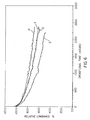
- FIG. 4 shows the normalized luminance as a function of operating time at 20mA/cm 2 current density for the four Devices A to D.
- the synergetic effect of doping exciton trapping dopant and hole trapping dopant was found with doping simultaneously with NPB and rubrene into Alq host.
- the decrease in luminance yield for Device D was the lowest as compared to the Devices A, B, and C.
- the change in luminance was unexpectedly lower than that possible from the additive effects of both dopants.
- the synergetic effect was such that better operational stability and efficiency were obtained at lower concentrations of the dopants. This resulted in more than two times improvement in operating lifetime and 10-20% increase in luminance efficiency, which could not be achieved with using either of the dopants with any amounts of doping concentrations.
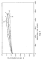
- FIG. 5 shows the operational stability of the drive voltage at 20mA/cm 2 current density.
- the Device D with the Alq emission layer doped with both rubrene and NPB dopants showed minimal change in the drive voltage.
- Device D has the highest operational stability among the four devices.
- the normalized luminance and the drive voltage was stable for a longer time for the devices of this invention.
- the 37.5 nm Alq emission layer contained 2% DCJTB luminescent dopant.
- the 37.5 nm Alq emission layer contained 2% DCJTB luminescent dopant and 10% rubrene exciton dopant.
- the 37.5 nm Alq emission layer contained 2% DCJTB luminescent dopant and 10% NPB hole trapping dopant.
- the 37.5 nm Alq emission layer contained three dopants, 2% DCJTB + 5% rubrene + 5% NPB.
- the luminance characteristics of these are included in Table 1.
- the Device E has 2.05 cd/A luminance yield at 20 mA/cm 2 current density.
- the luminance yield for Device F increased to 2.41 cd/A @20 mA/cm 2 .
- the Alq emission layer was doped with 2% DCJTB + 10% NPB for Device G, the luminance yield was 2.06 cd/A.
- the drive voltage at 20 mA/cm 2 current density was lowest for the Device H.
- the Device H prepared with the Alq host emission layer doped with three dopants: DCJTB luminescent dopant; rubrene exciton dopant and NPB hole trap dopant have higher luminance efficiency; lowest drive voltage and excellent color coordinates.
- FIG. 6 shows the operational luminance stability of the four Devices E to H. It is obvious that Device H prepared with all the three dopants, 2% DCJTB + 5% NPB +5% rubrene into the Alq host layer has the highest operational stability. This device also has the best color coordinates and the highest luminance efficiency and lowest drive voltage.
- FIG. 7 shows the operational voltage stability of the above four Devices E to H.
- the Device H prepared with all the three dopants, 2% DCJTB + 5% NPB +5% rubrene in Alq host layer has minimal increase in the drive voltage over the operational time and thus the highest operational voltage stability.
- third luminescent dopant such as DCJTB
- excellent red emission color coordinates were obtained with high luminance efficiency and lowest drive voltage, which could not be achieved with any other combination.
- the EL devices of this invention prepared with Alq emission containing rubrene and NPB with or without DCJTB luminescent dopant have significantly improved operational fade stability. These devices have higher luminance yield and lower drive voltage. These devices can be operated at higher current density with minimum degradation in the color coordinates and the luminance efficiency.
- the devices with the emission layer containing all the three dopants, rubrene exciton trap, NPB hole trap and DCJTB luminescent dopant have the highest luminance yield, lowest drive voltage, best chromiticity and the highest operational stability.
- the organic luminescent layer wherein concentration of the second dopant is in a range of 0.5% to 25% by volume of the organic luminescent layer.
- the organic luminescent layer wherein the host material includes:
- the organic luminescent layer wherein the first dopant includes a fluorescent hydrocarbon compound containing a polycyclic benzoid chromophoric unit.
- the organic luminescent layer wherein the second dopant includes aromatic tertiary amines.
- the organic luminescent layer wherein the aromatic tertiary amines are tetraaryldiamines.
- the organic luminescent layer wherein the aromatic tertiary amines include tetraaryldiamines having the formula: wherein:
- the organic luminescent layer wherein the third dopant includes DCM class of materials.
- the organic luminescent layer wherein the third dopant includes DCJTB.
- the organic luminescent layer wherein concentration of the first dopant is in a range of 0.5% to 25% by volume of the organic luminescent layer
- the organic luminescent layer wherein concentration of the second dopant is in a range of 0.5% to 25% by volume of the organic luminescent layer
- the organic luminescent layer wherein concentration of the third dopant is greater than 0.05% and less than 5% by volume of the organic luminescent layer.
- the organic luminescent layer wherein the combined concentration of the first, second, and third dopants is greater than 1.05% and less than 55% by volume of the organic luminescent layer.
Abstract
Description
- The present invention relates to organic electroluminescent devices and more particularly to an emission layer with suitable dopants for improving operational stability and efficiency of these devices.
- An OLED device includes a substrate, an anode, a hole-transporting layer made of an organic compound, an organic luminescent layer with suitable dopants, an organic electron transport layer, and a cathode. EL devices are attractive because of their low driving voltage, high luminance, wide-angle viewing and capability for full-color flat emission displays. Tang and others. described this multilayer EL device in their commonly assigned US-A-4,769,292 and US-A-4,885,211.
- The following patents and publications disclose the preparation of EL devices with improved operational lifetime. Structure modifications, stable cathode and confinement of carriers and their recombination in the emission zone achieved significant improvement in the operation stability of these devices. So and others. discussed an EL device in US-A-5,853,905 consisting of a single organic emission layer with a mixture of electron transport and hole transport material, sandwiched between anode and cathode. However, this device has low efficiency.
- Popovic and others. described an EL device in SPIE Conference proceedings Vol. 3476, p. 68-72, 1998 with improved efficiency and stability by mixing emitting electron transport material and the hole transport material. Chen and others. reported a highly efficient red color device where Alq emission layer is doped with DCJTB. (US-A-5,908,581 and Micromol. Symp. 25, 490 (1997)).
- Hamada and others. reported in Applied Phys. Lett. 75,1682 (1999) a red EL device by doping rubrene and DCM2 dopants into Alq emission layer. With the prospect of using these EL devices in display screens for laptop computers, digital personal organizers, cellular phone and so forth, there is a need for EL device with much stable operation for luminance and driving voltage.
- It is therefore an object of the present invention to provide an EL device with improved operational stability and luminance efficiency.
- This object is achieved by an organic luminescent layer for use in an electroluminescent device with improved operating life, comprising:
- a) an organic host material capable of sustaining both hole and electron injection and recombination; and
- b) at least two dopants:
- i) a first dopant capable of accepting energy of electron-hole combinations in the host material; and
- ii) a second dopant capable of trapping the holes from the host material; and
- c) the first dopant being selected so that the bandgap energy of the first dopant is less than the bandgap energy of the host material; and
- d) the second dopant being selected to have a hole trapping energy level above the valance band of the host material.
-
- A feature of the present invention is that by properly selecting the first and second dopants, the operating life of an electroluminescent device incorporating the electroluminescent layer can be significantly improved.
- Another feature of the invention is that it can be used to provide an electroluminescent device with improved chromaticity.
- Another feature of the invention is that it can be used to provide an electroluminescent device with improved operational stability at high luminance output.
- Another feature of the invention is that it can be used with a low voltage drive source.
- Quite unexpectedly, it has been found in this invention that synergetic effect of doping exciton trapping dopant and hole trapping dopant was such that better operational stability and efficiency were obtained at lower concentrations of the dopants. This resulted in improvements in operating lifetime and luminance efficiency. With an additional third luminescent dopant for controlling the color of the emission, excellent color chromicity was obtained, which could not be achieved with any other combination.
- The devices made in accordance with the present invention are highly stable and have excellent luminance properties.
- FIG. 1 is simple structure of an organic light-emitting device;
- FIG. 2 is a schematic diagram of an organic light-emitting device in which a light-emitting structure is deposited over an ITO anode with an emission layer prepared according to the present invention;
- FIG. 3 shows a graphic representation of the energy level diagram of the Alq host, exciton trapping dopant (EXD) (dopant 1), hole trapping dopant (HD) (dopant 2) and luminescent dopant (LD) (dopant 3) in the emission layer;
- FIG. 4 shows the relative normalized operational luminance as a function of operation time for doped EL devices;
- FIG. 5 shows the relative driving voltage as a function of operation time for the EL devices of FIG. 4;
- FIG. 6 shows the relative nomalized luminance as a function of operation time for doped EL devices; and
- FIG. 7 shows the relative driving voltage as a function of operation time for the EL devices of FIG. 6.
-
- The drawings are necessarily of a schematic nature, since the thicknesses of the individual layers are too thin and thickness differences of the various elements too great to permit depiction to scale or to permit convenient proportionate scaling.
- The light-emitting layer of the organic EL device comprises a luminescent or fluorescent material where electroluminescence is produced as a result of electron-hole pair recombination in this region. In the simplest construction, as shown in FIG. 1, the light-emitting
layer 108 is sandwiched betweenanode 104 andcathode 106. The light-emitting layer is a pure material with a high luminescent efficiency. A well known material is tris (8-quinolinato) aluminum, (Alq), which produces excellent green electroluminescence. - The
simple structure 100 can be modified to a three-layer structure as shown in FIG. 2, in which an additional electroluminescent layer is introduced between the hole and electron-transporting layers to function primarily as the site for hole-electron recombination and thus electroluminescence. In this respect, the functions of the individual organic layers are distinct and can therefore be optimized independently. Thus, the electroluminescent or recombination layer can be chosen to have a desirable EL color as well as high luminance efficiency. Likewise, the electron and hole transport layers can be optimized primarily for the carrier transport property. - Turning to FIG.2, a multilayer organic light-
emitting device 200 has a light-transmissive substrate 202 on which is disposed a light-transmissive anode 204. Theanode 204 comprises twolayers 204a and 204b. An organic light-emitting structure 208 is formed between theanode 204 and acathode 206. The organic light-emitting structure 208 is comprised of, in sequence, an organic hole-transportinglayer 210, an organic light-emittinglayer 212, and an organic electron-transporting layer 214. When an electrical potential difference (not shown) is applied between theanode 204 and thecathode 206, the cathode will inject electrons into the electron-transporting layer 214, and the electrons will migrate acrosslayer 214 to the light-emitting layer 212. At the same time, holes will be injected from theanode 204 into the hole-transportinglayer 210. The holes will migrate acrosslayer 210 and recombine with electrons at or near a junction formed between the hole-transportinglayer 210 and the light-emittinglayer 212. When a migrating electron drops from its conduction band to a valance band in filling a hole, energy is released as light, and is emitted through the light-transmissive anode 204 andsubstrate 202. - The organic EL devices can be viewed as a diode, which is forward biased when the anode is at a higher potential than the cathode. The anode and cathode of the organic EL device can each take any convenient conventional form, such as any of the various forms disclosed by Tang and others. US-A-4,885,211. Operating voltage can be substantially reduced when using a low-work function cathode and a high-work function anode. The preferred cathodes are those constructed of a combination of a metal having a work function less than 4.0 eV and one other metal, preferably a metal having a work function greater than 4.0 eV. The Mg: Ag of Tang and others. US-A-4,885,211 constitutes one preferred cathode construction. The A1:Mg cathodes of Vanslyke and others. US-A-5,776,622 has disclosed the use of a if/Al bilayer to enhanced electron injection in organic EL devices.
- Conventional anodes 204a are formed of a conductive and transparent oxide. Indium tin oxide has been widely used as the anode contact because of its transparency, good conductivity, and high work function.
- Preferred host materials for the emission layer include:
- a) Alq, and
- b)

- ; or c)

-
- Preferred materials for use in forming the electron-transporting layer of the organic EL devices of this invention are metal chelated oxinoid compounds, including chelates of oxine itself (also commonly referred to as 8-quinolinol or 8-hydroxyquinoline) as disclosed in US-A-4,885,211. Such compounds exhibit both high levels of performance and are readily fabricated in the form of thin layers.
- The light-
transmissive substrate 202 may be constructed of glass, quartz, or a plastic material. Preferred materials for use in forming the hole transport layer of the organic EL devices are tertiary amines as taught in Van Slyke US-A-4,539,507. Another class of preferred amines is tetraaryl amines. Preferred tetraaryldiamines include two diarylamino groups, such as indicated by formula (III), linked through an arylene group. Preferred tetraaryldiamines include those represented by formula (IV).
(IV)wherein:
- Ar, Ar1, Ar2 and Ar3 are independently selected from among phenyl, biphenyl and naphthyl moieties;
- L is a divalent naphthylene moiety or dn;
- d is a phenylene moiety;
- n is an integer of from I to 4; and
- at least one of Ar, Ar1, Ar2 and Ar3 is a naphthyl moiety when L is dn.
-
- The various alkyl, alkylene, aryl, and arylene moieties of the foregoing structural formulae (I), (II), (III), and (IV) can each in turn be substituted. Typical substituents include alkyl groups, alkoxy groups, aryl groups, aryloxy groups, and halogen such as fluoride, chloride, and bromide. The various alkyl and alkylene moieties typically contain from about 1 to 6 carbon atoms. The cycloalkyl moieties can contain from 3 to about 10 carbon atoms, but typically contain five, six, or seven ring carbon atoms, for example cyclopentyl, cyclohexyl, and cycloheptyl ring structures. When the aryl and arylene moieties are not fused aromatic ring moieties, they are preferably phenyl and phenylene moieties.
- Illustrative of useful selected (fused aromatic ring containing) aromatic tertiary amines are the following:
- ATA-1
- 4,4'-Bis[N-(1-naphthyl)-N-phenylamino]biphenyl (NPB)
- ATA-2
- 4,4"-Bis[N-(1-naphthyl)-N-phenylamino]-p-terphenyl
- ATA-3
- 4,4'-Bis[N-(2-naphthyl)-N-phenylamino]biphenyl
- ATA-4
- 4,4'-Bis[N-(3-acenaphthenyl)-N-phenyl-amino]biphenyl
- ATA-5
- 1,5-Bis[N-(1-naphthyl)-N-phenylamino]naphthalene
- ATA-6
- 4,4'-Bis[N-(9-anthryl)-N-phenylamino]-biphenyl
- ATA-7
- 4,4"-Bis[N-(1-anthryl)-N-phenylamino]-p-terphenyl
- ATA-8
- 4,4'-Bis[N-(2-phenanthryl)-N-phenyl-amino]biphenyl
- ATA-9
- 4,4'-Bis[N-(8-fluoranthenyl)-N-phenyl-amino]biphenyl
- ATA-10
- 4,4'-Bis[N-(2-pyrenyl)-N-phenylamino]bi-phenyl
- ATA-11
- 4,4'-Bis[N-(2-naphthacenyl)-N-phenyl-amino]biphenyl
- ATA-12
- 4,4'-Bis[N-(2-perylenyl)-N-phenylamino]biphenyl
- ATA-13
- 4,4'-Bis[N-(1-coronenyl)-N-phenylamino]biphenyl
- ATA-14
- 2,6-Bis(di-p-tolylamino)naphthalene
- ATA-15
- 2,6-Bis[di-( 1-naphtyl)amino]naphthalene
- ATA-16
- 2,6-Bis[N-(1-naphthyl)-N-(2-naphthyl)-amino]naphthalene
- ATA-17
- N,N,N',N'-Tetra(2-naphthyl)-4,4"-di-amino-p-terphenyl
- ATA-18
- 4,4'-Bis{N-phenyl-N-[4-(1-naphthyl)-phenyl]amino}biphenyl
- ATA-19
- 4,4'-Bis[N-phenyl-N-(2-pyrenyl)amino]biphenyl
- ATA-20
- 2,6-Bis[N,N-di(2-naphthyl)amine]fluorene
- ATA-21
- 1,5-Bis[N-(1-naphthyl)-N-phenylamino]naphthalene
- A preferred embodiment of the luminescent layer consists of a host material doped with fluorescent dyes. Using this method, highly efficient EL devices can be constructed. Simultaneously, the color of the EL devices can be tuned by using fluorescent dyes of different emission wavelengths in a common host material. Tang and others. in commonly assigned US-A-4,769,292 has described this dopant scheme in considerable details for EL devices using Alq as the host material.
- FIG. 3 describes the energy level diagram of the organic emission layer host and the three kinds of dopants used in this invention. This figure refers specifically to an organic emissive layer consisting of a Alq host material and the three dopants: exciton-trapping dopant, hole-trapping dopant, and luminescent dopant.
- A hole trap in Alq, for example, is defined as the dopant which has a bandgap greater than that of Alq, and is capable of donating an electron to Alq. The later condition is satisfied if the highest occupied molecular orbital (HOMO) of the dopant is higher (in electron energy scale) than that of Alq. Experimentally, the HOMO level is measured as the ionization potential with respect to the vacuum level. The ionization potential (IP) of the hole trapping dopant in Alq is determined to be lower than that of the (Alq) host. The IP of Alq is 5.62 eV. The hole trapping dopant, when filled is positively charged.
- Preferred materials for use as a hole trap dopant of the organic EL devices are tetraaryl amines. Some of the arylamines class materials and their ionization potentials are given below.


 An exciton trap in Alq, for example, is defined as the dopant, which has band gap energy less than that of Alq host material and the trap, when filled, remains electronically neutral.
- Preferred materials for uses as an exciton trap dopant of the organic EL devices are rubrene class materials. Some of the rubrene class materials and their ionization potentials are given below.


- The luminescent dopant has a bandgap less than the bandgap energy of the first exciton dopant. The exciton dopant is capable of accepting energy from the electron-hole combination in the host material and accepting energy transferred from the second dopant.
- Preferred materials for use as luminescent dopant of the organic EL devices is DCM class materials. Some of the DCJTB structures and their ionization potentials are given below.


- NPB has been used as a hole-trapping dopant, rubrene as an exciton trapping dopant, and DCJTB as a luminescent dopant into the Alq emission layer as examples illustrating this invention. The energy levels of these materials are shown in FIG. 3.
- Several devices were prepared on the glass substrate using ITO anode and Mg:Ag or LiF/Al cathode in accordance with a device structure as described in FIG. 2. The structure of the device is glass substrate/ITO anode/CFx hole injection layer/ NPB hole transport layer/Alq emission layer with dopant(s)/Alq electron transport layer/Mg:Ag or LiF/Al.
- The ranges of concentration of various dopants in the Alq emission layer used in the EL devices are preferably as follows:
Exciton trapping dopant = 1- 25 %, hole trapping dopant = 0.1- 35 %,
and luminescent dopant = 0.05 - 4%. - Several devices have been prepared using the above dopants. The results are summarized in Tables 1 and 2.
- Devices prepared doping both exciton dopant and hole trapping dopant have shown significantly higher efficiency and the operational stability as compared to the devices doped with either dopant. Furthermore, the synergetic effect of doping exciton trapping dopant and hole trapping dopant was such that better operational stability and efficiency were obtained. With the addition of third luminescent dopant, excellent color coordinates were obtained with high luminance efficiency, which could not be achieved with any other combination.
- The invention and its advantages are further illustrated by the specific examples which follow. The term "percentage" indicates the volume percentage of a particular dopant with respect to the host material.
- An EL device was constructed in the following manner:
- Substrates coated with 80 nm ITO were sequentially ultrasonicated in a commercial detergent, rinsed in deionized water, degreased in toluene vapor. These substrates were treated with an oxygen plasma for about one minute and coated with 1 nm fluorocarbon layer by plasma assisted deposition of CHF3.
- These substrates were loaded into a deposition chamber for organic layers and cathode depositions.
- Device A was prepared by sequential deposition of 150 nm NPB hole transporting layer, followed by 37.5 nm Alq emission layer without any dopant (EML), 37.5 nm Alq electron transport layer (ETL), then 0.5 nm LiF and 200 nm Al as a part of cathode. The above sequence completed the deposition of the EL device.
- The EL device was then hermetically packaged in a dry glove box filled with nitrogen for protection against ambient environment. The ITO patterned substrates used for preparing these EL devices contained several icons. Each individual icon of the device was tested for current voltage characteristics and the electroluminescence yield.
- Device B was prepared following the same sequence as Device A except the 37.5 Alq emission layer was doped with 10% rubrene, exciton dopant 1.
- Device C was prepared following the same sequence as Device A except the 37.5 Alq emission layer was doped with 10% NPB,
hole trap dopant 2. - Device D was prepared following the same sequence as Device A except the 37.5 Alq emission layer was doped with 5% rubrene and 5% NPB. The deposition rate and thus the volume percentage of the Alq host and the two dopants was controlled by the boat temperature.
- The luminance characteristics of these devices are shown in Table 1. The Device A has 3.17 cd/A luminance yield at 20 mA/cm2 current density. This device has EL peak position at 532 nm and has green color. When the Alq emission layer was doped with 10% rubrene for Device B, the luminance yield was 4.68 cd/A. The EL peak position was at 568 nm giving yellow emission. When the Alq emission layer was doped with 10% NPB, the luminance yield for Device C increased to 3.27 cd/A @20 mA/cm2. The EL peak position is at 528 nm and has green color. When the Alq emission layer was co-doped with 5% rubrene and 5% NPB, the luminance yield for the Device D was 4.95 cd/A and the EL peak position was at 568 nm giving yellow emission.
- The operational stability of the encapsulated devices in ambient environments has been found by measuring the changes in the drive voltage and the luminance as a function of time when four different icons of each of these devices were operated at a constant current density of 20, 40, 60 and 80 mA/cm2. The half-life times for these devices are given in Table 1.
Luminance performance of devices A to H with different dopants Device Luminescent layer Luminance Yield @20 mA/cm2 (cd/A) EL Peak Wavelength (nm) CIEx CIEy Drivevoltage @ 20mA/cm2 (volts) Device A Alq 3.17 524 0.334 0.531 8.50 Device B Alq + 10% Rubrene 4.68 568 0.519 0.476 7.90 Device C Alq + 10% NPB 3.26 528 0.346 0.538 8.70 Device D Alq + 5% Rubrene + 5% NPB 4.95 568 0.518 0.478 8.30 Device E Alq + 2% DCJT-B 2.05 628 0.640 0.355 9.20 Device F Alq + 2% DCJT-B + 10% Rubrene 2.41 632 0.650 0.345 9.00 Device G Alq + 2% DCJT-B + 10% NPB 2.08 628 0.645 0.353 9.10 Device H Alq + 2% DCJT-B + 5% NPB + 5% Rubrene 2.76 632 0.650 0.350 8.50 - FIG. 4 shows the normalized luminance as a function of operating time at 20mA/cm2 current density for the four Devices A to D. The synergetic effect of doping exciton trapping dopant and hole trapping dopant was found with doping simultaneously with NPB and rubrene into Alq host. The decrease in luminance yield for Device D was the lowest as compared to the Devices A, B, and C. The change in luminance was unexpectedly lower than that possible from the additive effects of both dopants. The synergetic effect was such that better operational stability and efficiency were obtained at lower concentrations of the dopants. This resulted in more than two times improvement in operating lifetime and 10-20% increase in luminance efficiency, which could not be achieved with using either of the dopants with any amounts of doping concentrations.
- FIG. 5 shows the operational stability of the drive voltage at 20mA/cm2 current density. Unexpectedly, again the Device D with the Alq emission layer doped with both rubrene and NPB dopants showed minimal change in the drive voltage. Thus, Device D has the highest operational stability among the four devices. Thus, the normalized luminance and the drive voltage was stable for a longer time for the devices of this invention.
- In accordance with the method described for Devices A-D, except that the dopants in the 37.5 nm Alq emission layer.
- For Device E , the 37.5 nm Alq emission layer contained 2% DCJTB luminescent dopant.
- For Device F, the 37.5 nm Alq emission layer contained 2% DCJTB luminescent dopant and 10% rubrene exciton dopant.
- For Device G, the 37.5 nm Alq emission layer contained 2% DCJTB luminescent dopant and 10% NPB hole trapping dopant.
- For Device H, the 37.5 nm Alq emission layer contained three dopants, 2% DCJTB + 5% rubrene + 5% NPB.
- The luminance characteristics of these are included in Table 1. The Device E has 2.05 cd/A luminance yield at 20 mA/cm2 current density. This device has EL peak position at 628 nm and has red color having color coordinates CIEx = 0.64 and CIEy = 0.35. When the Alq emission layer was doped with 2% DCJTB + 10% rubrene, the luminance yield for Device F increased to 2.41 cd/A @20 mA/cm2. The EL peak position is at 628 nm and has red color having color coordinates CIEx = 0.64 and CIEy = 0.34. When the Alq emission layer was doped with 2% DCJTB + 10% NPB for Device G, the luminance yield was 2.06 cd/A. The EL peak position was at 628 nm giving red emission at 628 nm and color coordinates CIEx = 0.64 and CIEy = 0.34. When the Alq emission layer was co-doped three dopants, 2% DCJTB + 5% rubrene + 5% NPB, the luminance yield for the Device H was 2.76 cd/A and the EL peak position was at 628 nm giving red emission at 628 nm and color coordinates of CIEx = 0.65 and CIEy = 0.34. The drive voltage at 20 mA/cm2 current density was lowest for the Device H. Thus the Device H prepared with the Alq host emission layer doped with three dopants: DCJTB luminescent dopant; rubrene exciton dopant and NPB hole trap dopant have higher luminance efficiency; lowest drive voltage and excellent color coordinates.
- The operational stability of these encapsulated devices has been found by measuring the changes in the luminance and the drive voltage as a function of time. Again four icons of each device was operated at the current density of 20, 40, 60 and 80 20 mA/cm2. The half-life times for these devices are included in Table 2.
Operational Half-life times of devices A to H with different dopants Device Luminescent layer Half life @J=80 mA/cm2 (Hours) Half life @J=60 mA/cm2 (Hours) Half life @J=40 mA/cm2 (Hours) Half life @J=20 mA/cm2 (Hours) Device A Alq 156 161 38 1000 Device B Alq + 10% Rubrene 455 542 1103 3000 Device C Alq+ 10% NPB 348 525 1025 3250 Device D Alq + 5% Rubrene + 5% NPB 900 1300 2200 5000 Device E Alq + 2% DCJT-B 361 510 901 2250 Device F Alq + 2% DCJT-B + 10% Rubrene 487 710 1482 3500 Device G Alq + 2% DCJT-B + 10% NPB 563 822 1557 4000 Device H Alq + 2% DCJT-B + 5% NPB + 5% Rubrene 901 1353 2250 >6000 - FIG. 6 shows the operational luminance stability of the four Devices E to H. It is obvious that Device H prepared with all the three dopants, 2% DCJTB + 5% NPB +5% rubrene into the Alq host layer has the highest operational stability. This device also has the best color coordinates and the highest luminance efficiency and lowest drive voltage.
- FIG. 7 shows the operational voltage stability of the above four Devices E to H. Again, the Device H prepared with all the three dopants, 2% DCJTB + 5% NPB +5% rubrene in Alq host layer has minimal increase in the drive voltage over the operational time and thus the highest operational voltage stability.
- With the addition of third luminescent dopant, such as DCJTB, excellent red emission color coordinates were obtained with high luminance efficiency and lowest drive voltage, which could not be achieved with any other combination.
- Thus the EL devices of this invention prepared with Alq emission containing rubrene and NPB with or without DCJTB luminescent dopant have significantly improved operational fade stability. These devices have higher luminance yield and lower drive voltage. These devices can be operated at higher current density with minimum degradation in the color coordinates and the luminance efficiency. The devices with the emission layer containing all the three dopants, rubrene exciton trap, NPB hole trap and DCJTB luminescent dopant, have the highest luminance yield, lowest drive voltage, best chromiticity and the highest operational stability.
- Other features of the invention are included below.
- The organic luminescent layer wherein concentration of the second dopant is in a range of 0.5% to 25% by volume of the organic luminescent layer.
- The organic luminescent layer wherein the host material includes:
- a) Alq; and
- b)

- ; or c)

-
- The organic luminescent layer wherein the first dopant includes a fluorescent hydrocarbon compound containing a polycyclic benzoid chromophoric unit.
- The organic luminescent layer wherein the second dopant includes aromatic tertiary amines.
- The organic luminescent layer wherein the aromatic tertiary amines are tetraaryldiamines.
- The organic luminescent layer wherein the aromatic tertiary amines include tetraaryldiamines having the formula:wherein:

- Ar, Ar1, Ar2 and Ar3 are independently selected from among phenyl, biphenyl and naphthyl moieties;
- L is a divalent naphthylene moiety or dn;
- d is a phenylene moiety;
- n is an integer of from 1 to 4, and
- at least one of Ar, Ar1, Ar2 and Ar3 is a naphthyl moiety when L is dn.
-
- The organic luminescent layer wherein the third dopant includes DCM class of materials.
- The organic luminescent layer wherein the third dopant includes DCJTB.
- The organic luminescent layer wherein concentration of the first dopant is in a range of 0.5% to 25% by volume of the organic luminescent layer
- The organic luminescent layer wherein concentration of the second dopant is in a range of 0.5% to 25% by volume of the organic luminescent layer
- The organic luminescent layer wherein concentration of the third dopant is greater than 0.05% and less than 5% by volume of the organic luminescent layer.
- The organic luminescent layer wherein the combined concentration of the first, second, and third dopants is greater than 1.05% and less than 55% by volume of the organic luminescent layer.
Claims (10)
- An organic luminescent layer for use in an electroluminescent device with improved operating life, comprising:a) an organic host material capable of sustaining both hole and electron injection and recombination; andb) at least two dopants:i) a first dopant capable of accepting energy of electron hole combinations in the host material; andii) a second dopant capable of trapping the holes from the host material; andc) the first dopant being selected so that the bandgap energy of the first dopant is less than the bandgap energy of the host material; andd) the second dopant being selected to have a hole trapping energy level above the valance band of the host material.
- The organic luminescent layer of claim I wherein the host material includes tris(8-hydroxy quinolinol)aluminum.
- The organic luminescent layer of claim 1 wherein the first dopant includes a fluorescent hydrocarbon compound containing a polycyclic benzoid chromophoric unit.
- The organic luminescent layer of claim 1 wherein the second dopant includes aromatic tertiary amines.
- The organic luminescent layer of claim 4 wherein the aromatic tertiary amines are tetraaryldiamines.
- The organic luminescent layer of claim 5 wherein the aromatic tertiary amines include tetraaryldiamines having the formula:wherein:
 Ar, Ar1, Ar2 and Ar3 are independently selected from among phenyl, biphenyl and naphthyl moieties;L is a divalent naphthylene moiety or dn;d is a phenylene moiety;n is an integer of from 1 to 4; andat least one of Ar, Ar1, Ar2 and Ar3 is a naphthyl moiety when L is dn.
 - The organic luminescent layer of claim 1 wherein concentration of the first dopant is in a range of 0.5% to 25% by volume of the organic luminescent layer.
- An organic luminescent layer for use in an electroluminescent device with improved operating life, comprising:a) an organic host material capable of sustaining both hole and electron injection and recombination; andb) at least three dopants:i) a first dopant capable of accepting energy of electron hole combination in the host material;ii) a second dopant capable of trapping the holes from the host material; andiii) a third dopant capable of accepting energy from the electron hole combination in the host material and accepting energy transferred from the second dopant;c) the first dopant being selected so that the bandgap energy of the first dopant is less than the bandgap energy of the host material; andd) the second dopant being selected to have a hole trapping energy level above the valance band of the host material; ande) the third dopant having a bandgap energy less than the bandgap energy of the first dopant.
- An electroluminescent device having a cathode and an anode and at least one organic luminescent layer, comprising:a) an organic host material capable of sustaining both hole and electron injection and recombination; andb) at least two dopants:i) a first dopant capable of accepting energy of electron hole combinations in the host material; andii) a second dopant capable of trapping the holes from the host material; andc) the first dopant being selected so that the bandgap energy of the first dopant is less than the bandgap energy of the host material; andd) the second dopant being selected to have a hole trapping energy level above the valance band of the host material.
- An electroluminescent device having a cathode and an anode and at least one organic luminescent layer, comprising:a) an organic host material capable of sustaining both hole and electron injection and recombination; andb) three dopants:i) a first dopant capable of accepting energy of electron hole combinations in the host material;ii) a second dopant capable of trapping the holes from the host material; andii) a third dopant capable of accepting energy from the electron hole combination in the host material and accepting energy transferred from the second dopant; andc) the first dopant being selected so that the bandgap energy of the first dopant is less than the bandgap energy of the host material;d) the second dopant being selected to have a hole trapping energy level above the valance band of the host material; ande) the third dopant being selected to have a bandgap energy less than the bandgap energy of the first dopant
Applications Claiming Priority (2)
| Application Number | Priority Date | Filing Date | Title |
|---|---|---|---|
| US589731 | 2000-06-08 | ||
| US09/589,731 US6475648B1 (en) | 2000-06-08 | 2000-06-08 | Organic electroluminescent devices with improved stability and efficiency |
Publications (3)
| Publication Number | Publication Date |
|---|---|
| EP1162674A2 true EP1162674A2 (en) | 2001-12-12 |
| EP1162674A3 EP1162674A3 (en) | 2002-06-26 |
| EP1162674B1 EP1162674B1 (en) | 2004-03-31 |
Family
ID=24359262
Family Applications (1)
| Application Number | Title | Priority Date | Filing Date |
|---|---|---|---|
| EP01202011A Expired - Lifetime EP1162674B1 (en) | 2000-06-08 | 2001-05-28 | Organic electroluminescent devices with improved stability and efficiency |
Country Status (7)
| Country | Link |
|---|---|
| US (1) | US6475648B1 (en) |
| EP (1) | EP1162674B1 (en) |
| JP (1) | JP2002038140A (en) |
| KR (1) | KR20010111055A (en) |
| CN (1) | CN1346233A (en) |
| DE (1) | DE60102515T2 (en) |
| TW (1) | TW496101B (en) |
Cited By (13)
| Publication number | Priority date | Publication date | Assignee | Title |
|---|---|---|---|---|
| EP1221473A1 (en) * | 2001-01-02 | 2002-07-10 | Eastman Kodak Company | Organic light emitting diode device with three component emitting layer |
| EP1359790A2 (en) * | 2002-04-24 | 2003-11-05 | Eastman Kodak Company | Organic light-emitting diode devices with improved operational stability |
| EP1408722A1 (en) * | 2002-10-11 | 2004-04-14 | Eastman Kodak Company | Method of designing an oled display with optimized lifetime |
| WO2005033246A1 (en) * | 2003-09-15 | 2005-04-14 | Eastman Kodak Company | Green organic light-emitting diodes |
| EP1578175A1 (en) * | 2002-11-18 | 2005-09-21 | Idemitsu Kosan Co., Ltd. | Organic electroluminescence element |
| WO2006047075A1 (en) * | 2004-10-25 | 2006-05-04 | Eastman Kodak Company | Organic light-emitting devices with improved performance |
| EP1665897A1 (en) * | 2003-09-24 | 2006-06-07 | Fuji Photo Film Co., Ltd. | Electroluminescent device |
| US7175922B2 (en) | 2003-10-22 | 2007-02-13 | Eastman Kodak Company | Aggregate organic light emitting diode devices with improved operational stability |
| US7241512B2 (en) | 2002-04-19 | 2007-07-10 | 3M Innovative Properties Company | Electroluminescent materials and methods of manufacture and use |
| US7264889B2 (en) | 2002-04-24 | 2007-09-04 | Eastman Kodak Company | Stable electroluminescent device |
| US7368178B2 (en) | 2004-01-08 | 2008-05-06 | Eastman Kodak Company | Stable organic light-emitting devices using aminoanthracenes |
| US10593886B2 (en) | 2013-08-25 | 2020-03-17 | Molecular Glasses, Inc. | OLED devices with improved lifetime using non-crystallizable molecular glass mixture hosts |
| US10693094B2 (en) | 2015-09-30 | 2020-06-23 | Semiconductor Energy Laboratory Co., Ltd. | Light-emitting element, display device, electronic device, and lighting device |
Families Citing this family (50)
| Publication number | Priority date | Publication date | Assignee | Title |
|---|---|---|---|---|
| KR100721656B1 (en) | 2005-11-01 | 2007-05-23 | 주식회사 엘지화학 | Organic electronic devices |
| DE10048812B4 (en) * | 2000-09-29 | 2005-07-28 | Orga Systems Gmbh | Data carrier with customizable by means of high-energy beam authenticity features |
| JP2002235077A (en) * | 2001-02-08 | 2002-08-23 | Nippon Steel Chem Co Ltd | Organic el material and organic el element using the same |
| KR100454500B1 (en) * | 2001-12-22 | 2004-10-28 | 한국전자통신연구원 | High efficient organic electro-luminescence device and method for manufacturing the same |
| JP3819789B2 (en) * | 2002-03-05 | 2006-09-13 | 三洋電機株式会社 | Organic electroluminescence display device and manufacturing method thereof |
| JP2004079512A (en) * | 2002-06-17 | 2004-03-11 | Sanyo Electric Co Ltd | Organic el panel and its manufacturing method |
| KR100480442B1 (en) * | 2002-08-17 | 2005-04-06 | 한국과학기술연구원 | White organic light-emitting materials prepared by light-doping and electroluminescent devices using the same |
| US20040132228A1 (en) * | 2002-12-17 | 2004-07-08 | Honeywell International Inc. | Method and system for fabricating an OLED |
| JP2004207102A (en) | 2002-12-26 | 2004-07-22 | Optrex Corp | Organic electroluminescent element |
| US20040126617A1 (en) * | 2002-12-31 | 2004-07-01 | Eastman Kodak Company | Efficient electroluminescent device |
| CN100426553C (en) * | 2003-01-22 | 2008-10-15 | 清华大学 | Organicelectroluminescent device and its preparation method |
| KR100501702B1 (en) * | 2003-03-13 | 2005-07-18 | 삼성에스디아이 주식회사 | Organic electroluminescent display device |
| TWI224473B (en) * | 2003-06-03 | 2004-11-21 | Chin-Hsin Chen | Doped co-host emitter system in organic electroluminescent devices |
| JP4567962B2 (en) | 2003-07-25 | 2010-10-27 | 三洋電機株式会社 | Electroluminescence element and electroluminescence panel |
| US6875524B2 (en) * | 2003-08-20 | 2005-04-05 | Eastman Kodak Company | White light-emitting device with improved doping |
| KR20050039674A (en) * | 2003-10-24 | 2005-04-29 | 펜탁스 가부시키가이샤 | White organic electroluminescent device |
| CN100369287C (en) * | 2003-11-05 | 2008-02-13 | 友达光电股份有限公司 | Organic electroluminescence assembly and manufacturing method thereof |
| US7538355B1 (en) | 2003-11-20 | 2009-05-26 | Raja Singh Tuli | Laser addressed monolithic display |
| US7252893B2 (en) * | 2004-02-17 | 2007-08-07 | Eastman Kodak Company | Anthracene derivative host having ranges of dopants |
| US7504163B2 (en) * | 2004-07-12 | 2009-03-17 | Eastman Kodak Company | Hole-trapping materials for improved OLED efficiency |
| US20060141287A1 (en) * | 2004-08-19 | 2006-06-29 | Eastman Kodak Company | OLEDs with improved operational lifetime |
| US20060040131A1 (en) * | 2004-08-19 | 2006-02-23 | Eastman Kodak Company | OLEDs with improved operational lifetime |
| JP4653469B2 (en) | 2004-12-01 | 2011-03-16 | 出光興産株式会社 | Organic electroluminescence device |
| US7351999B2 (en) * | 2004-12-16 | 2008-04-01 | Au Optronics Corporation | Organic light-emitting device with improved layer structure |
| US7517595B2 (en) * | 2005-03-10 | 2009-04-14 | Eastman Kodak Company | Electroluminescent devices with mixed electron transport materials |
| US8057916B2 (en) | 2005-04-20 | 2011-11-15 | Global Oled Technology, Llc. | OLED device with improved performance |
| US20060240281A1 (en) * | 2005-04-21 | 2006-10-26 | Eastman Kodak Company | Contaminant-scavenging layer on OLED anodes |
| US20070252516A1 (en) * | 2006-04-27 | 2007-11-01 | Eastman Kodak Company | Electroluminescent devices including organic EIL layer |
| US20070126347A1 (en) * | 2005-12-01 | 2007-06-07 | Eastman Kodak Company | OLEDS with improved efficiency |
| EP1974590B1 (en) | 2006-01-18 | 2020-03-04 | LG Display Co., Ltd. | Oled having stacked organic light-emitting units |
| US9118020B2 (en) | 2006-04-27 | 2015-08-25 | Global Oled Technology Llc | Electroluminescent devices including organic eil layer |
| EP2355198B1 (en) | 2006-05-08 | 2015-09-09 | Global OLED Technology LLC | OLED electron-injecting layer |
| EP1863105B1 (en) * | 2006-06-02 | 2020-02-19 | Semiconductor Energy Laboratory Co., Ltd. | Light-emitting element, light-emitting device, and electronic device |
| US7667391B2 (en) * | 2006-08-04 | 2010-02-23 | Eastman Kodak Company | Electrically excited organic light-emitting diodes with spatial and spectral coherence |
| JP5202051B2 (en) * | 2007-04-27 | 2013-06-05 | キヤノン株式会社 | Organic electroluminescence device |
| KR100899423B1 (en) * | 2007-08-16 | 2009-05-27 | 삼성모바일디스플레이주식회사 | Organic light emitting display device and method of fabricating the same |
| CN100484353C (en) | 2008-01-29 | 2009-04-29 | 清华大学 | Organic electroluminescent part |
| JP5077007B2 (en) * | 2008-03-26 | 2012-11-21 | Dic株式会社 | Dispersed inorganic electroluminescence panel |
| KR100924145B1 (en) * | 2008-06-10 | 2009-10-28 | 삼성모바일디스플레이주식회사 | Organic light emitting diode and fabrication method of the same |
| CN105742515A (en) * | 2009-05-29 | 2016-07-06 | 株式会社半导体能源研究所 | Light-Emitting Element, Light-Emitting Device, Lighting Device, and Electronic Appliance |
| WO2011030450A1 (en) * | 2009-09-11 | 2011-03-17 | 富士電機ホールディングス株式会社 | Organic light-emitting element |
| JP5511454B2 (en) * | 2010-03-19 | 2014-06-04 | ユー・ディー・シー アイルランド リミテッド | Organic electroluminescence device |
| WO2011132550A1 (en) * | 2010-04-20 | 2011-10-27 | コニカミノルタホールディングス株式会社 | Organic electroluminescent element, display device, and illumination device |
| JP5211123B2 (en) * | 2010-09-06 | 2013-06-12 | 出光興産株式会社 | Organic electroluminescence device |
| KR102083256B1 (en) * | 2012-09-28 | 2020-03-03 | 에스에프씨 주식회사 | Organic EL material-containing solution and organic EL device including the same |
| KR102114878B1 (en) * | 2014-02-27 | 2020-05-26 | 삼성디스플레이 주식회사 | Organic light emitting diode display |
| US9929365B2 (en) | 2014-05-28 | 2018-03-27 | The Regents Of The University Of Michigan | Excited state management |
| KR102281311B1 (en) * | 2015-04-14 | 2021-07-26 | 덕산네오룩스 주식회사 | Compound for organic electronic element, organic electronic element using the same, and an electronic device thereof |
| US10290816B2 (en) | 2015-11-16 | 2019-05-14 | The Regents Of The University Of Michigan | Organic electroluminescent materials and devices |
| CN111554821B (en) * | 2020-05-14 | 2023-10-24 | 京东方科技集团股份有限公司 | Organic electroluminescent device, display panel and display device |
Citations (2)
| Publication number | Priority date | Publication date | Assignee | Title |
|---|---|---|---|---|
| US5601903A (en) * | 1993-08-27 | 1997-02-11 | Sanyo Electric Co., Ltd. | Organic electroluminescent elements |
| WO1999053724A1 (en) * | 1998-04-10 | 1999-10-21 | The Trustees Of Princeton University | Color-tunable organic light emitting devices |
Family Cites Families (8)
| Publication number | Priority date | Publication date | Assignee | Title |
|---|---|---|---|---|
| US4539507A (en) | 1983-03-25 | 1985-09-03 | Eastman Kodak Company | Organic electroluminescent devices having improved power conversion efficiencies |
| US4885211A (en) | 1987-02-11 | 1989-12-05 | Eastman Kodak Company | Electroluminescent device with improved cathode |
| US4769292A (en) | 1987-03-02 | 1988-09-06 | Eastman Kodak Company | Electroluminescent device with modified thin film luminescent zone |
| US5059062A (en) | 1990-06-14 | 1991-10-22 | Pat Bresnahan | Concrete path paver with removeable slip-forming screed |
| US5776622A (en) | 1996-07-29 | 1998-07-07 | Eastman Kodak Company | Bilayer eletron-injeting electrode for use in an electroluminescent device |
| US5908581A (en) * | 1997-04-07 | 1999-06-01 | Eastman Kodak Company | Red organic electroluminescent materials |
| US5853905A (en) | 1997-09-08 | 1998-12-29 | Motorola, Inc. | Efficient single layer electroluminescent device |
| US5935721A (en) * | 1998-03-20 | 1999-08-10 | Eastman Kodak Company | Organic electroluminescent elements for stable electroluminescent |
-
2000
- 2000-06-08 US US09/589,731 patent/US6475648B1/en not_active Expired - Lifetime
-
2001
- 2001-04-17 TW TW090109166A patent/TW496101B/en not_active IP Right Cessation
- 2001-05-28 DE DE60102515T patent/DE60102515T2/en not_active Withdrawn - After Issue
- 2001-05-28 EP EP01202011A patent/EP1162674B1/en not_active Expired - Lifetime
- 2001-06-06 CN CN01120883A patent/CN1346233A/en active Pending
- 2001-06-08 KR KR1020010032151A patent/KR20010111055A/en not_active Application Discontinuation
- 2001-06-08 JP JP2001174150A patent/JP2002038140A/en active Pending
Patent Citations (2)
| Publication number | Priority date | Publication date | Assignee | Title |
|---|---|---|---|---|
| US5601903A (en) * | 1993-08-27 | 1997-02-11 | Sanyo Electric Co., Ltd. | Organic electroluminescent elements |
| WO1999053724A1 (en) * | 1998-04-10 | 1999-10-21 | The Trustees Of Princeton University | Color-tunable organic light emitting devices |
Non-Patent Citations (3)
| Title |
|---|
| FATEMI D J ET AL: "HIGHLY FLUORESCENT MOLECULAR ORGANIC COMPOSITES FOR LIGHT-EMITTING DIODES" SYNTHETIC METALS, ELSEVIER SEQUOIA, LAUSANNE, CH, vol. 85, 1997, pages 1225-1228, XP002911748 ISSN: 0379-6779 * |
| HAMADA Y ET AL: "INFLUENCE OF THE EMISSION SITE ON THE RUNNING DURABILITY OF ORGANIC ELECTROLUMINESCENT DEVICES" JAPANESE JOURNAL OF APPLIED PHYSICS, PUBLICATION OFFICE JAPANESE JOURNAL OF APPLIED PHYSICS. TOKYO, JP, vol. 34, no. PART 2, 1 July 1995 (1995-07-01), pages 824-826, XP002061754 ISSN: 0021-4922 * |
| Y. HAMADA ET AL.: "Red organic light-emitting diodes using an emitting assist dopant" APPLIED PHYS. LETT., vol. 75, no. 12, 20 September 1999 (1999-09-20), pages 1682-1684, XP002196211 * |
Cited By (21)
| Publication number | Priority date | Publication date | Assignee | Title |
|---|---|---|---|---|
| US6720090B2 (en) | 2001-01-02 | 2004-04-13 | Eastman Kodak Company | Organic light emitting diode devices with improved luminance efficiency |
| EP1221473A1 (en) * | 2001-01-02 | 2002-07-10 | Eastman Kodak Company | Organic light emitting diode device with three component emitting layer |
| US7442421B2 (en) | 2002-04-19 | 2008-10-28 | 3M Innovative Properties Company | Electroluminescent materials and methods of manufacture and use |
| US7241512B2 (en) | 2002-04-19 | 2007-07-10 | 3M Innovative Properties Company | Electroluminescent materials and methods of manufacture and use |
| US7264889B2 (en) | 2002-04-24 | 2007-09-04 | Eastman Kodak Company | Stable electroluminescent device |
| EP1359790A2 (en) * | 2002-04-24 | 2003-11-05 | Eastman Kodak Company | Organic light-emitting diode devices with improved operational stability |
| EP1359790A3 (en) * | 2002-04-24 | 2003-11-19 | Eastman Kodak Company | Organic light-emitting diode devices with improved operational stability |
| CN100452475C (en) * | 2002-04-24 | 2009-01-14 | 伊斯曼柯达公司 | Organic light-emitting diode equipment with improved operation stability |
| EP1408722A1 (en) * | 2002-10-11 | 2004-04-14 | Eastman Kodak Company | Method of designing an oled display with optimized lifetime |
| US6911961B2 (en) | 2002-10-11 | 2005-06-28 | Eastman Kodak Company | Method of designing an OLED display with lifetime optimized primaries |
| EP1578175A1 (en) * | 2002-11-18 | 2005-09-21 | Idemitsu Kosan Co., Ltd. | Organic electroluminescence element |
| EP1578175A4 (en) * | 2002-11-18 | 2008-11-26 | Idemitsu Kosan Co | Organic electroluminescence element |
| WO2005033246A1 (en) * | 2003-09-15 | 2005-04-14 | Eastman Kodak Company | Green organic light-emitting diodes |
| EP1665897A1 (en) * | 2003-09-24 | 2006-06-07 | Fuji Photo Film Co., Ltd. | Electroluminescent device |
| EP1665897A4 (en) * | 2003-09-24 | 2010-07-14 | Fujifilm Corp | Electroluminescent device |
| US8048535B2 (en) | 2003-09-24 | 2011-11-01 | Fujifiilm Corporation | Electroluminescent device |
| US7175922B2 (en) | 2003-10-22 | 2007-02-13 | Eastman Kodak Company | Aggregate organic light emitting diode devices with improved operational stability |
| US7368178B2 (en) | 2004-01-08 | 2008-05-06 | Eastman Kodak Company | Stable organic light-emitting devices using aminoanthracenes |
| WO2006047075A1 (en) * | 2004-10-25 | 2006-05-04 | Eastman Kodak Company | Organic light-emitting devices with improved performance |
| US10593886B2 (en) | 2013-08-25 | 2020-03-17 | Molecular Glasses, Inc. | OLED devices with improved lifetime using non-crystallizable molecular glass mixture hosts |
| US10693094B2 (en) | 2015-09-30 | 2020-06-23 | Semiconductor Energy Laboratory Co., Ltd. | Light-emitting element, display device, electronic device, and lighting device |
Also Published As
| Publication number | Publication date |
|---|---|
| DE60102515D1 (en) | 2004-05-06 |
| CN1346233A (en) | 2002-04-24 |
| US6475648B1 (en) | 2002-11-05 |
| DE60102515T2 (en) | 2005-03-24 |
| KR20010111055A (en) | 2001-12-15 |
| EP1162674B1 (en) | 2004-03-31 |
| EP1162674A3 (en) | 2002-06-26 |
| JP2002038140A (en) | 2002-02-06 |
| TW496101B (en) | 2002-07-21 |
Similar Documents
| Publication | Publication Date | Title |
|---|---|---|
| EP1162674B1 (en) | Organic electroluminescent devices with improved stability and efficiency | |
| US6696177B1 (en) | White organic electroluminescent devices with improved stability and efficiency | |
| US6720092B2 (en) | White organic light-emitting devices using rubrene layer | |
| KR100884436B1 (en) | Organic light-emitting device having a color-neutral dopant in a hole-transport layer and/or in an electron-transport layer | |
| EP1286569B1 (en) | White organic light-emitting devices with improved efficiency | |
| US6727644B2 (en) | Organic light-emitting device having a color-neutral dopant in an emission layer and in a hole and/or electron transport sublayer | |
| KR101457576B1 (en) | Stabilized White-Emitting OLED Device | |
| US7037601B2 (en) | White light-emitting device structures | |
| EP1492167A2 (en) | White light-emitting oled device having a blue light-emitting layer doped with an electron-transporting or a hole-transporting material or both | |
| US6692846B2 (en) | Organic electroluminescent device having a stabilizing dopant in a hole-transport layer or in an electron-transport layer distant from the emission layer | |
| JP2007525023A (en) | Use of crystallization-inhibiting materials in organic electroluminescent devices | |
| US20080176099A1 (en) | White oled device with improved functions | |
| EP1009042A2 (en) | Electroliuminescent device with arylethylene derivatives in hole transport layer | |
| Choo et al. | Luminance mechanisms in green organic light-emitting devices fabricated utilizing tris (8-hydroxyquinoline) aluminum/4, 7-diphenyl-1, 10-phenanthroline multiple heterostructures acting as an electron transport layer | |
| WO2004107471A1 (en) | White light-emitting device structures |
Legal Events
| Date | Code | Title | Description |
|---|---|---|---|
| PUAI | Public reference made under article 153(3) epc to a published international application that has entered the european phase |
Free format text: ORIGINAL CODE: 0009012 |
|
| AK | Designated contracting states |
Kind code of ref document: A2 Designated state(s): AT BE CH CY DE DK ES FI FR GB GR IE IT LI LU MC NL PT SE TR |
|
| AX | Request for extension of the european patent |
Free format text: AL;LT;LV;MK;RO;SI |
|
| PUAL | Search report despatched |
Free format text: ORIGINAL CODE: 0009013 |
|
| RIC1 | Information provided on ipc code assigned before grant |
Free format text: 7H 01L 51/20 A, 7C 09K 11/06 B, 7H 05B 33/00 B, 7H 05B 33/02 B, 7H 05B 33/14 B |
|
| AK | Designated contracting states |
Kind code of ref document: A3 Designated state(s): AT BE CH CY DE DK ES FI FR GB GR IE IT LI LU MC NL PT SE TR |
|
| AX | Request for extension of the european patent |
Free format text: AL;LT;LV;MK;RO;SI |
|
| 17P | Request for examination filed |
Effective date: 20021130 |
|
| AKX | Designation fees paid |
Designated state(s): DE FR GB |
|
| 17Q | First examination report despatched |
Effective date: 20030404 |
|
| GRAP | Despatch of communication of intention to grant a patent |
Free format text: ORIGINAL CODE: EPIDOSNIGR1 |
|
| GRAS | Grant fee paid |
Free format text: ORIGINAL CODE: EPIDOSNIGR3 |
|
| GRAA | (expected) grant |
Free format text: ORIGINAL CODE: 0009210 |
|
| AK | Designated contracting states |
Kind code of ref document: B1 Designated state(s): DE FR GB |
|
| REG | Reference to a national code |
Ref country code: GB Ref legal event code: FG4D |
|
| REG | Reference to a national code |
Ref country code: IE Ref legal event code: FG4D |
|
| REF | Corresponds to: |
Ref document number: 60102515 Country of ref document: DE Date of ref document: 20040506 Kind code of ref document: P |
|
| ET | Fr: translation filed | ||
| PLBE | No opposition filed within time limit |
Free format text: ORIGINAL CODE: 0009261 |
|
| STAA | Information on the status of an ep patent application or granted ep patent |
Free format text: STATUS: NO OPPOSITION FILED WITHIN TIME LIMIT |
|
| REG | Reference to a national code |
Ref country code: IE Ref legal event code: MM4A |
|
| 26N | No opposition filed |
Effective date: 20050104 |
|
| PGFP | Annual fee paid to national office [announced via postgrant information from national office to epo] |
Ref country code: GB Payment date: 20050406 Year of fee payment: 5 |
|
| PGFP | Annual fee paid to national office [announced via postgrant information from national office to epo] |
Ref country code: FR Payment date: 20050517 Year of fee payment: 5 |
|
| PGFP | Annual fee paid to national office [announced via postgrant information from national office to epo] |
Ref country code: DE Payment date: 20050531 Year of fee payment: 5 |
|
| PG25 | Lapsed in a contracting state [announced via postgrant information from national office to epo] |
Ref country code: DE Free format text: LAPSE BECAUSE OF THE APPLICANT RENOUNCES Effective date: 20060221 |
|
| PG25 | Lapsed in a contracting state [announced via postgrant information from national office to epo] |
Ref country code: GB Free format text: LAPSE BECAUSE OF NON-PAYMENT OF DUE FEES Effective date: 20060528 |
|
| GBPC | Gb: european patent ceased through non-payment of renewal fee |
Effective date: 20060528 |
|
| REG | Reference to a national code |
Ref country code: FR Ref legal event code: ST Effective date: 20070131 |
|
| PG25 | Lapsed in a contracting state [announced via postgrant information from national office to epo] |
Ref country code: FR Free format text: LAPSE BECAUSE OF NON-PAYMENT OF DUE FEES Effective date: 20060531 |