EP1159934B1 - Implantable tubular device (stent) - Google Patents
Implantable tubular device (stent) Download PDFInfo
- Publication number
- EP1159934B1 EP1159934B1 EP20010112897 EP01112897A EP1159934B1 EP 1159934 B1 EP1159934 B1 EP 1159934B1 EP 20010112897 EP20010112897 EP 20010112897 EP 01112897 A EP01112897 A EP 01112897A EP 1159934 B1 EP1159934 B1 EP 1159934B1
- Authority
- EP
- European Patent Office
- Prior art keywords
- stent
- implantable
- deformable portion
- deformable
- implantable device
- Prior art date
- Legal status (The legal status is an assumption and is not a legal conclusion. Google has not performed a legal analysis and makes no representation as to the accuracy of the status listed.)
- Expired - Lifetime
Links
Images


Classifications
-
- A—HUMAN NECESSITIES
- A61—MEDICAL OR VETERINARY SCIENCE; HYGIENE
- A61F—FILTERS IMPLANTABLE INTO BLOOD VESSELS; PROSTHESES; DEVICES PROVIDING PATENCY TO, OR PREVENTING COLLAPSING OF, TUBULAR STRUCTURES OF THE BODY, e.g. STENTS; ORTHOPAEDIC, NURSING OR CONTRACEPTIVE DEVICES; FOMENTATION; TREATMENT OR PROTECTION OF EYES OR EARS; BANDAGES, DRESSINGS OR ABSORBENT PADS; FIRST-AID KITS
- A61F2/00—Filters implantable into blood vessels; Prostheses, i.e. artificial substitutes or replacements for parts of the body; Appliances for connecting them with the body; Devices providing patency to, or preventing collapsing of, tubular structures of the body, e.g. stents
- A61F2/82—Devices providing patency to, or preventing collapsing of, tubular structures of the body, e.g. stents
- A61F2/86—Stents in a form characterised by the wire-like elements; Stents in the form characterised by a net-like or mesh-like structure
- A61F2/90—Stents in a form characterised by the wire-like elements; Stents in the form characterised by a net-like or mesh-like structure characterised by a net-like or mesh-like structure
- A61F2/91—Stents in a form characterised by the wire-like elements; Stents in the form characterised by a net-like or mesh-like structure characterised by a net-like or mesh-like structure made from perforated sheet material or tubes, e.g. perforated by laser cuts or etched holes
- A61F2/915—Stents in a form characterised by the wire-like elements; Stents in the form characterised by a net-like or mesh-like structure characterised by a net-like or mesh-like structure made from perforated sheet material or tubes, e.g. perforated by laser cuts or etched holes with bands having a meander structure, adjacent bands being connected to each other
- A61F2002/91516—Stents in a form characterised by the wire-like elements; Stents in the form characterised by a net-like or mesh-like structure characterised by a net-like or mesh-like structure made from perforated sheet material or tubes, e.g. perforated by laser cuts or etched holes with bands having a meander structure, adjacent bands being connected to each other the meander having a change in frequency along the band
-
- A—HUMAN NECESSITIES
- A61—MEDICAL OR VETERINARY SCIENCE; HYGIENE
- A61F—FILTERS IMPLANTABLE INTO BLOOD VESSELS; PROSTHESES; DEVICES PROVIDING PATENCY TO, OR PREVENTING COLLAPSING OF, TUBULAR STRUCTURES OF THE BODY, e.g. STENTS; ORTHOPAEDIC, NURSING OR CONTRACEPTIVE DEVICES; FOMENTATION; TREATMENT OR PROTECTION OF EYES OR EARS; BANDAGES, DRESSINGS OR ABSORBENT PADS; FIRST-AID KITS
- A61F2/00—Filters implantable into blood vessels; Prostheses, i.e. artificial substitutes or replacements for parts of the body; Appliances for connecting them with the body; Devices providing patency to, or preventing collapsing of, tubular structures of the body, e.g. stents
- A61F2/82—Devices providing patency to, or preventing collapsing of, tubular structures of the body, e.g. stents
- A61F2/86—Stents in a form characterised by the wire-like elements; Stents in the form characterised by a net-like or mesh-like structure
- A61F2/90—Stents in a form characterised by the wire-like elements; Stents in the form characterised by a net-like or mesh-like structure characterised by a net-like or mesh-like structure
- A61F2/91—Stents in a form characterised by the wire-like elements; Stents in the form characterised by a net-like or mesh-like structure characterised by a net-like or mesh-like structure made from perforated sheet material or tubes, e.g. perforated by laser cuts or etched holes
- A61F2/915—Stents in a form characterised by the wire-like elements; Stents in the form characterised by a net-like or mesh-like structure characterised by a net-like or mesh-like structure made from perforated sheet material or tubes, e.g. perforated by laser cuts or etched holes with bands having a meander structure, adjacent bands being connected to each other
- A61F2002/91525—Stents in a form characterised by the wire-like elements; Stents in the form characterised by a net-like or mesh-like structure characterised by a net-like or mesh-like structure made from perforated sheet material or tubes, e.g. perforated by laser cuts or etched holes with bands having a meander structure, adjacent bands being connected to each other within the whole structure different bands showing different meander characteristics, e.g. frequency or amplitude
-
- A—HUMAN NECESSITIES
- A61—MEDICAL OR VETERINARY SCIENCE; HYGIENE
- A61F—FILTERS IMPLANTABLE INTO BLOOD VESSELS; PROSTHESES; DEVICES PROVIDING PATENCY TO, OR PREVENTING COLLAPSING OF, TUBULAR STRUCTURES OF THE BODY, e.g. STENTS; ORTHOPAEDIC, NURSING OR CONTRACEPTIVE DEVICES; FOMENTATION; TREATMENT OR PROTECTION OF EYES OR EARS; BANDAGES, DRESSINGS OR ABSORBENT PADS; FIRST-AID KITS
- A61F2/00—Filters implantable into blood vessels; Prostheses, i.e. artificial substitutes or replacements for parts of the body; Appliances for connecting them with the body; Devices providing patency to, or preventing collapsing of, tubular structures of the body, e.g. stents
- A61F2/82—Devices providing patency to, or preventing collapsing of, tubular structures of the body, e.g. stents
- A61F2/86—Stents in a form characterised by the wire-like elements; Stents in the form characterised by a net-like or mesh-like structure
- A61F2/90—Stents in a form characterised by the wire-like elements; Stents in the form characterised by a net-like or mesh-like structure characterised by a net-like or mesh-like structure
- A61F2/91—Stents in a form characterised by the wire-like elements; Stents in the form characterised by a net-like or mesh-like structure characterised by a net-like or mesh-like structure made from perforated sheet material or tubes, e.g. perforated by laser cuts or etched holes
- A61F2/915—Stents in a form characterised by the wire-like elements; Stents in the form characterised by a net-like or mesh-like structure characterised by a net-like or mesh-like structure made from perforated sheet material or tubes, e.g. perforated by laser cuts or etched holes with bands having a meander structure, adjacent bands being connected to each other
- A61F2002/91533—Stents in a form characterised by the wire-like elements; Stents in the form characterised by a net-like or mesh-like structure characterised by a net-like or mesh-like structure made from perforated sheet material or tubes, e.g. perforated by laser cuts or etched holes with bands having a meander structure, adjacent bands being connected to each other characterised by the phase between adjacent bands
-
- A—HUMAN NECESSITIES
- A61—MEDICAL OR VETERINARY SCIENCE; HYGIENE
- A61F—FILTERS IMPLANTABLE INTO BLOOD VESSELS; PROSTHESES; DEVICES PROVIDING PATENCY TO, OR PREVENTING COLLAPSING OF, TUBULAR STRUCTURES OF THE BODY, e.g. STENTS; ORTHOPAEDIC, NURSING OR CONTRACEPTIVE DEVICES; FOMENTATION; TREATMENT OR PROTECTION OF EYES OR EARS; BANDAGES, DRESSINGS OR ABSORBENT PADS; FIRST-AID KITS
- A61F2/00—Filters implantable into blood vessels; Prostheses, i.e. artificial substitutes or replacements for parts of the body; Appliances for connecting them with the body; Devices providing patency to, or preventing collapsing of, tubular structures of the body, e.g. stents
- A61F2/82—Devices providing patency to, or preventing collapsing of, tubular structures of the body, e.g. stents
- A61F2/86—Stents in a form characterised by the wire-like elements; Stents in the form characterised by a net-like or mesh-like structure
- A61F2/90—Stents in a form characterised by the wire-like elements; Stents in the form characterised by a net-like or mesh-like structure characterised by a net-like or mesh-like structure
- A61F2/91—Stents in a form characterised by the wire-like elements; Stents in the form characterised by a net-like or mesh-like structure characterised by a net-like or mesh-like structure made from perforated sheet material or tubes, e.g. perforated by laser cuts or etched holes
- A61F2/915—Stents in a form characterised by the wire-like elements; Stents in the form characterised by a net-like or mesh-like structure characterised by a net-like or mesh-like structure made from perforated sheet material or tubes, e.g. perforated by laser cuts or etched holes with bands having a meander structure, adjacent bands being connected to each other
- A61F2002/9155—Adjacent bands being connected to each other
- A61F2002/91558—Adjacent bands being connected to each other connected peak to peak
-
- A—HUMAN NECESSITIES
- A61—MEDICAL OR VETERINARY SCIENCE; HYGIENE
- A61F—FILTERS IMPLANTABLE INTO BLOOD VESSELS; PROSTHESES; DEVICES PROVIDING PATENCY TO, OR PREVENTING COLLAPSING OF, TUBULAR STRUCTURES OF THE BODY, e.g. STENTS; ORTHOPAEDIC, NURSING OR CONTRACEPTIVE DEVICES; FOMENTATION; TREATMENT OR PROTECTION OF EYES OR EARS; BANDAGES, DRESSINGS OR ABSORBENT PADS; FIRST-AID KITS
- A61F2/00—Filters implantable into blood vessels; Prostheses, i.e. artificial substitutes or replacements for parts of the body; Appliances for connecting them with the body; Devices providing patency to, or preventing collapsing of, tubular structures of the body, e.g. stents
- A61F2/82—Devices providing patency to, or preventing collapsing of, tubular structures of the body, e.g. stents
- A61F2/86—Stents in a form characterised by the wire-like elements; Stents in the form characterised by a net-like or mesh-like structure
- A61F2/90—Stents in a form characterised by the wire-like elements; Stents in the form characterised by a net-like or mesh-like structure characterised by a net-like or mesh-like structure
- A61F2/91—Stents in a form characterised by the wire-like elements; Stents in the form characterised by a net-like or mesh-like structure characterised by a net-like or mesh-like structure made from perforated sheet material or tubes, e.g. perforated by laser cuts or etched holes
- A61F2/915—Stents in a form characterised by the wire-like elements; Stents in the form characterised by a net-like or mesh-like structure characterised by a net-like or mesh-like structure made from perforated sheet material or tubes, e.g. perforated by laser cuts or etched holes with bands having a meander structure, adjacent bands being connected to each other
- A61F2002/9155—Adjacent bands being connected to each other
- A61F2002/91566—Adjacent bands being connected to each other connected trough to trough
-
- A—HUMAN NECESSITIES
- A61—MEDICAL OR VETERINARY SCIENCE; HYGIENE
- A61F—FILTERS IMPLANTABLE INTO BLOOD VESSELS; PROSTHESES; DEVICES PROVIDING PATENCY TO, OR PREVENTING COLLAPSING OF, TUBULAR STRUCTURES OF THE BODY, e.g. STENTS; ORTHOPAEDIC, NURSING OR CONTRACEPTIVE DEVICES; FOMENTATION; TREATMENT OR PROTECTION OF EYES OR EARS; BANDAGES, DRESSINGS OR ABSORBENT PADS; FIRST-AID KITS
- A61F2230/00—Geometry of prostheses classified in groups A61F2/00 - A61F2/26 or A61F2/82 or A61F9/00 or A61F11/00 or subgroups thereof
- A61F2230/0002—Two-dimensional shapes, e.g. cross-sections
- A61F2230/0004—Rounded shapes, e.g. with rounded corners
- A61F2230/0013—Horseshoe-shaped, e.g. crescent-shaped, C-shaped, U-shaped
Definitions
- the present invention relates to an implantable tubular device such as a stent to be implanted in human body such as a blood vessel, a bile duct, a trachea, an esophagus, an ureter, and internal organs to improve a stenotic lesion or a total occlusion formed in the lumens.
- a stent to be implanted in human body such as a blood vessel, a bile duct, a trachea, an esophagus, an ureter, and internal organs to improve a stenotic lesion or a total occlusion formed in the lumens.
- the stent which is a tubular-shaped medical appliance is implanted at the stenotic lesion or the total occlusion to expand them and secure the lumen thereof.
- the stents are classified into self-expandable stents and balloon expandable stents, depending on the function thereof and the implantation method.
- Balloon expandable stents have no dilating function. After a balloon expandable stent is inserted into a target lesion, a balloon expandable inside the stent in an extent almost equal to the normal diameter of the lumen of the target lesion is inflated to dilate (plastic deformation) the stent by the inflation force of the balloon so that the stent comes in close contact with the inner surface of the target lesion.
- a known method comprises reducing the number of joining portions (articulation) disposed between the adjacent annular units (i.e. mono-link stent).
- An implantable tubular device as defined in the preamble of claim 1 is disclosed in WO 94/17754 .
- WO 01/00112 can be considered as part of the state of the art only relevant to questions of novelty pursuant to Article 54(3) EPC.
- This document discloses a variable thickness stent with deformable portions located at connecting portions of respective wavy element. The deformable portions do not cross the wavy elements. It is impossible to obtain a satisfactory flexibility.
- the present invention has been made to solve the above-described problems. Therefore, it is an object of the present invention to provide an implantable tubular device, for example, a stent, having a deformable portion to improve the flexibility of an annular unit of the device so that the device can pass easily through a bent portion of a human body
- an implantable tubular device formed as a substantially tubular body having a diameter so set that said device can be inserted into a lumen of a human body and capable of dilating radially upon application of a force acting radially outwardly from an interior of said tubular body, which device comprises a plurality of wavy annular members each formed of a wavy element and arranged in an axial direction of said device and connection portions each connecting said wavy annular members to each other in the axial direction of said device.
- Each of said wavy annular members has a plurality of deformable portions each consisting of a groove having a width of 1 ⁇ m - 100 ⁇ m provided on a surface of said device.
- Each of said wavy annular members has a bent portion which is not connected to the other wavy annular members in such a way that said deformable portions cross said wavy annular member including said bent portion.
- An implantable tubular device 1 of the present invention to be implanted in a lumen is formed substantially tubular and has an easy deformable portion formed on a peripheral surface thereof, with the deformable portion forming a predetermined angle with respect to the axial direction of the device 1. It can be said that the deformable portion is a weak portion or a thin portion. The deformable portion is easy to deform in comparison with a remainder part of the device
- the implantable tubular device 1 of the present invention has the deformable portion, the implantable tubular device has a high flexibility and can pass through a bent or curved portion of a human body easily and leaves little hysteresis of deformation which occurs at the time of insertion thereof in the human body.
- the implantable tubular device of the present invention to be implanted in lumens of the human body includes a stent and a stent graft that is used to improve a stenotic lesion or a total occlusion formed in the lumens such as a blood vessel, a bile duct, a trachea, an esophagus, an ureter, and the like.
- the deformable portion includes a portion which is thinner than the other portion (undeformable portion) of the device and thus more flexible than the other portion; a portion which has pores and is thus more flexible than the other portion (undeformable portion) of the device; or a portion which is made of a material having a lower strength than the other portion (undeformable portion) of the device and is thus more frail than the other portion.
- the deformable portion of the implantable tubular device 1 shown in Fig. 1 forms a predetermined angle with respect to the axial direction of the device. Accordingly, the implantable tubular device can be curved easily along a curved portion formed in a lumen. The deformable portion is so formed that it makes a predetermined angle with respect to the axial direction of the device.
- the deformable portion is so formed that it is not parallel with the axial direction of the device. Therefore, when the implantable tubular device is inserted into the human body and diametrically enlarged, the deformable portion does not cause the device to be broken.
- the implantable tubular device of the present invention is formed as a substantial tubular body.
- the implantable tubular device 1 has a diameter so set that it can be inserted into a lumen in the human body and can dilate radially upon application of a force acting radially outwardly from the interior of the tubular body.
- the implantable tubular device has a plurality of wavy annular members each formed of a wavy element and arranged in the axial direction thereof; and connection portions each connecting the adjacent wavy annular members to each other in the axial direction thereof.
- the wavy annular member has the deformable portion formed on a bent portion thereof not connected to the other wavy annular members in such a way that the deformable portion crosses the wavy annular member.
- the implantable tubular device consists of a stent 1.
- the implantable tubular device (stent) 1 is a so-called balloon expandable stent. That is, the stent 1 is formed as substantially tubular body and has a diameter so set that the stent 1 can be inserted into the human body. The stent 1 can dilate radially outwardly upon application of a force acting radially outwardly from the interior of the tubular body.
- the stent 1 has a frame structure.
- the stent 1 of the embodiment includes annular units 31, 32, 33, 34, 35, 36, 37, 38, 39, 40, 41, and 42 each consisting of a first wavy annular member 2a annularly formed of a wavy element (preferably having no edge); a second wavy annular member 2b disposed in the axial direction of the stent 1 in such a way that a mountain thereof is proximate to a valley of the first wavy annular member 2a and annularly formed of a wavy element (preferably having no edge); and a plurality of connection portions 4 (preferably having no edge) connecting the valley of the first wavy annular member 2a and the mountain of the second wavy annular member 2b to each other.
- the stent 1 further includes joining portions 51, 52, 53, 54, 55, 56, 57, 58, 59, 60, and 61 (preferably having no edge) arranged in the axial direction of the stent 1 and each connecting the wavy elements (the second wavy annular member 2b and the first wavy annular member 2a) of the adjacent annular units to each other.
- the stent 1 is a tubular body constructed of a plurality of annular units connected to each other with the joining portions.
- one annular unit is annularly formed of a plurality of rhombic elements annularly arranged.
- each of the first wavy annular member 2a and the second wavy annular member 2b is constructed of an tubularly continuous endless wavy material having six mountains and valleys.
- the number of the mountains (or valleys) of the tubular bodies is four to seven.
- Each of a plurality of short connection portions connects the valley of the second wavy annular member and the mountain of the second wavy annular member 2b disposed in the axial direction of the stent 1 in such a way that the mountain thereof is proximate to the valley of the first wavy annular member 2a. In this manner, one annular unit is constructed.
- connection portions 4 connect all the valleys of the second wavy annular member and all the mountains of the second wavy annular member 2b to each other.
- One annular unit has six (equal to the number of mountains or valleys of the tubular body) connection portions 4.
- the material for the stent 1 has a certain degree of compatibility with an organism.
- the material for the stent 1 has a certain degree of compatibility with an organism.
- a noble metal such as gold and platinum after the stent is fabricated into a final shape.
- the stainless steel SUS 316L most corrosion-resistant of the above metals can be preferably used.
- the annealed stent has a lower force of restoring to an original state after it is dilated and has a lower force of restoring to an original linear state when it is dilated at a curved portion of a blood vessel. This minimizes physical stimulation to the inner wall of the curved blood vessel, thus reducing the cause of a recurrence of stenosis.
- the stent is preferably annealed by heating it to 900 to 1200 °C in an inert gas atmosphere (e.g., a mixture gas of nitrogen and hydrogen) so that no oxide film is formed on the surface of the stent and then slowly cooling it.
- an inert gas atmosphere e.g., a mixture gas of nitrogen and hydrogen
- the stent 1 has a diameter of favorably 0.8 to 1.8 mm and more favorably of 1.0 to 1.6 mm in an undilated state.
- the stent 1 has a length favorably of 9 to 40 mm in an undilated state.
- the length of each of the wavy annular members 2a, 2b has a length of 0.7 to 2.0 mm.
- the length of each of the annular units 31 through 42 is favorably 1.5 - 4.0 mm and more favorably 2.0 - 3.0 mm.
- the length of each connection portion 4 is favorably 0.01 - 0.5 mm.
- the number of the annular units 31 through 42 is 3 to 50.
- the constituent elements (annular member) of the adjacent annular units have an axial overlap length of about 0.5 to 1 mm.
- the distance between the center of one annular unit and that of the annular unit adjacent thereto is preferably 1.3 to 2.5 mm.
- the length of each of the joining portions 51, 52, 53, 54, 55, 56, 57, 58, 59, 60, and 61 is preferably 1.4 to 2.7 mm.
- the angle of inclination (the angle of inclination of the joining portion with respect to the longitudinal direction of the stent in a development view) of each of the joining portions 51 through 61 with respect to the axis of the stent is favorably 0° to 30° and more favorably 5° to 25°.
- each of the wavy annular members 2a, 2b of the stent 1 and that of each of the joining portions 51, 52, 53, 54, 55, 56, 57, 58, 59, 60, and 61 are favorably 0.05 to 0.15 mm and more favorably 0.08 to 0.12 mm.
- the width of each of the wavy annular members 2a, 2b and that of each of the joining portions 51, 52, 53, 54, 55, 56, 57, and 58 are favorably 0.07 to 0.15 mm and more favorably 0.08 to 0.12 mm.
- the thickness of the connection portion 4 of the stent 1 is favorably 0.05 - 0.12 mm and more favorably 0.06 - 0.10 mm.
- connection portion 4 of the stent 1 is favorably 0.01 - 0.05 mm and more favorably 0.02 to 0.04 mm.
- the sectional area of the connection portion 4 is favorably 1/50 to 1/2 of that of the other parts (annular member and joining portion) and more favorably 1/20 to 1/10 of that of the other parts.
- the stent 1 has the deformable portion formed on the wavy annular member constructing the stent 1. More specifically, the deformable portion is formed on a bent portion of the wavy annular member not connected to the other wavy annular members in such a way that the deformable portion crosses the wavy annular member. Therefore, the free bent portion of the wavy annular member not connected to the other wavy annular members is allowed to deform easily. Further, a deformation hysteresis that occurs when the stent 1 is inserted into the human body does not remain in the free bent portion. The deformable portion is entirely formed on the stent 1 to deform the entire stent easily.
- the deformable portion is formed on the bent portion of the wavy annular member not connected to the other wavy annular members in such a way that the deformable portion crosses the wavy annular member. More specifically, when the deformable portion is viewed in the axial direction of the wavy annular member, namely, in the axial direction of the stent (device), the deformable portion is formed on the bent portion of the wavy annular member not connected to the other wavy annular members in such a way that the deformable portion crosses the wavy annular member. That is, the deformable portion forms 20 - 90° and favorably 70 - 90° with the axial direction of the device. In the embodiment, the deformable portion is almost orthogonal (90° ) to the axial direction of the device.
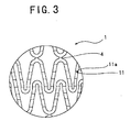
- the deformable portion is formed in such a way that when the deformable portion is prolonged, it continuously goes around the periphery of the device. That is, when the deformable portion is prolonged, it forms an endless annular configuration. Further the deformable portions are formed on the bent portion of the wavy annular member in such a way that they are substantially parallel with one another. Thereby the implantable tubular device has substantially annular grooves. Thus the implantable tubular device is prevented from being bent in a particular direction. That is, the implantable tubular device is capable of easily flexing in any directions.
- the depth of a groove 11a is not definite but different according to the diameter and thickness of the stent.
- the depth of the groove 11a is favorably 5 - 50% of the thickness of the device and more favorably 10 - 20% thereof.
- the width of the groove 11a is favorably 1 ⁇ m - 100 ⁇ m and more favorably 5 ⁇ m - 50 ⁇ m. It is preferable that the interval between the adjacent deformable portions (the interval between the grooves, namely, the interval between the grooves in the axial direction of stent) is much shorter than the axial length of the annular unit. Thus it is preferable that the interval between the adjacent deformable portions is 1/80 - 1/8 of the axial length of the annular unit to improve the flexibility of the annular unit.
- the interval between the adjacent grooves of the stent 1 is favorably 0.01 - 1mm and more favorably 0.05 - 0.5mm.
- the deformable portions (groove 11a) 11 of the stent 1 of the embodiment are formed at regular intervals but may be formed at irregular intervals or at regular intervals in one region and at irregular intervals in other region.
- the interval between the adjacent grooves in the axial direction of the stent does not necessarily have to be uniform.
- the interval between the adjacent grooves at both axial ends of the stent 1 may be different from that between the adjacent grooves at the axial central portion thereof to vary the flexibility of the stent 1, depending on a portion thereof. More specifically, the interval between the adjacent grooves may be short at both axial ends of the stent 1 and long at the axial central portion thereof to allow both axial ends of the stent 1 to be more flexible than the axial central portion thereof.
- the groove 11a of the embodiment is formed on only the outer surface of the stent (device) 1. But the groove 11a may be formed on only the inner surface thereof or on both the outer and inner surfaces thereof. In the case where the groove 11a is formed on both the outer and inner surfaces of the substantially tubular body, it is not preferable to form the grooves on concentric circles of the tubular body to prevent the groove formed on the outer surface thereof and the groove formed on the inner surface thereof from being coincident with each other in the axial direction of the tubular body. Thereby the deformable portion does not cause a low-strength portion to be formed on the device.
- the implantable tubular device is formed as a frame structure by removing a portion of a tubular body (metal pipe) other than a portion thereof which is to be formed as a frame structure.
- the stent is formed by removing an unnecessary portion from a metal pipe by using an etching process, known as photo-fabrication, using a mask and chemicals; electric discharge machining; mechanical machining using a die; or laser machining method.
- an etching process known as photo-fabrication, using a mask and chemicals; electric discharge machining; mechanical machining using a die; or laser machining method.
- polish the edge of the frame structure by using chemical polishing or electro-polishing.
- the groove 11a may be formed after a cylindrical member formed from the above-described forming material is processed into the shape of the stent; before the cylindrical member is processed into the shape of the stent; or at the time when the cylindrical member is processed into the shape of the stent.
- the groove 11a is formed by laser processing method of processing the groove by emitting laser to the cylindrical member, etching method using photoresist technique or mechanical machining. After the groove 11a is formed, it is preferable to polish the surface of the groove by using chemical polishing or electro-polishing.
- the groove is formed on the inner surface of the stent 1 (in the case where the deformable portion is formed from the inner surface of the stent 1)
- the annular units are connected with each other with one joining portion, i.e., the stent of mono-link type has been exemplified.
- the annular units may be connected with each other with a plurality of joining portions. That is, the stent of the present invention may be of link type.
- the deformable portion does not necessarily have to consist of the groove but may consist of a thin portion having a predetermined width.
- Fig. 4 is a front view of a stent according to another embodiment of the present invention.
- Fig. 5 is a development view of the stent of Fig. 4.
- Fig. 6 is a partly enlarged front view of the stent of Fig. 4.
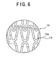
- the implantable tubular device of this embodiment is different from the above-described embodiment in that a stent 10 and a deformable portion 13 of this embodiment are different from the stent 1 and the deformable portion 11 of the above-described embodiment respectively.
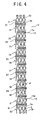
- the deformable portion 13 is so formed that when the deformable portion is prolonged, a spiral is formed on the peripheral surface of the device.
- the number of spirals is 1 - 500. In this embodiment, the number of spirals is 34.
- the interval between adjacent spirals (grooves) in the axial direction of the stent is preferably 0.05 - 0.5mm.
- the inclination of the spiral with respect to the axial direction of the stent is preferably 60 - 80°.
- the depth of a groove 13a is not definite but different according to the diameter and thickness of the stent.
- the depth of the groove 13a is favorably 5 - 50% of the thickness of the device and more favorably 10 - 20% thereof.
- the width of the groove 13a is favorably 1 ⁇ m - 100 ⁇ m and more favorably 5 ⁇ m - 10 ⁇ m.
- the inclination of the spiral formed by the groove with respect to the axial direction of the stent in other words, the pitch between the adjacent spirals formed by the groove does not necessarily have to be equal to each other.
- the pitch between the adjacent spirals at both axial ends of the stent 10 may be different from that between the adjacent spirals at the axial central portion thereof to vary the flexibility of the stent 10, depending on a portion thereof. More specifically, the pitch between the adjacent spirals may be short at both axial ends of the stent 10 and long at the axial central portion thereof to allow both ends of the stent 10 to be more flexible than the axial central portion thereof.
- the groove 13a of the present invention is formed on only the outer surface of the stent (device) 10. But the groove 13a may be formed on only the inner surface thereof or on both the outer and inner surfaces thereof. In the case where the groove 13a is formed on both the outer and inner surfaces of the substantially tubular body, it is preferable to prevent the groove formed on the outer surface thereof and the groove formed on the inner surface thereof from being coincident with each other in the axial direction of the tubular body. Thereby the deformable portion does not cause a low-strength portion to be formed on the device.
- the deformable portion does not necessarily have to consist of the groove but may consist of a thin portion having a predetermined width.
- the deformable portion 13 of the stent 10 can be formed by the methods that are used to form the above-described deformable portion 11 of the stent 1.
- the implantable tubular device of the present invention may be produced from a spiral deformable portion-provided tubular body formed by connecting axially adjacent coiled wire members to each other directly or indirectly.
- the implantable tubular device of the present invention is formed as a frame structure by removing a portion of the prepared tubular body other than a portion thereof which is to be formed as the device.
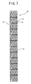
- Fig. 7 shows the tubular body, composed of the coiled wire member, which is used as the device of the present invention with solid lines.
- Fig. 7 also shows the frame structure formed by removing the portion of the tubular body other than the portion thereof which is to be formed as the implantable tubular device with broken lines.
- the tubular body is produced by directly or indirectly connecting adjacent coiled wire members 21 to each other in the axial direction of the coil.
- the tubular body has the spiral deformable portions 15.
- connection portion 16 of the tubular body 20 is formed smaller than the diameter of the wire member 21 to deform the connection portion 16 more easily than the body of the wire member 21.
- the wire members 21 adjacent to each other in the axial direction of the coil may be connected to each other directly (direct connection) by welding or the like or indirectly (indirect connection) through other member having a high flexibility. In the direct and indirect connections, the entire adjacent surfaces of the wire members 21 do not necessarily have to be connected to each other but a part of the adjacent surfaces thereof can be connected to each other.
- the thickness of the deformable portion 15 does not necessarily have to be smaller than the diameter of the wire member 21, provided that the implantable tubular device can deform (flex) easily, with the deformable portion acting as the point of origin of the deformation.
- the thickness of the deformable portion 15 may be almost equal to the diameter of the wire member 21 by interposing other member between the adjacent wire members 21.
- the tubular body 20 has a diameter favorably 0.8 mm to 1.8 mm and more favorably 1.0 mm to 1.6 mm.
- the axial length of the tubular body is favorably 3 mm to 50mm and more favorably 5 mm - 30mm.
- the wire member has a diameter favorably 0.01 to 0.2mm and more favorably 0.05 to 0.1mm.
- the interval between the adjacent wire members is favorably 0 to 0.5mm and more favorably 0 - 0.1mm. It is preferable to make the wire member of a material similar to the material for the stent 1.
- the method of shaping the implantable tubular device in other words, as the method of producing the frame structure by removing the portion of the prepared tubular body other than the portion thereof which is to be formed as the device, etching method known as photo-fabrication, using a mask and chemicals; electric discharge machining using a die; mechanical machining or laser processing method can be used.
- the implantable tubular device of this embodiment can be easily bent from the deformable portion which is formed at the connection portion of the adjacent wire members 21. Thus the implantable tubular device can pass smoothly through a bent portion of the human body.
- the implantable tubular device of the present invention may be produced from an annular deformable portions-provided tubular body formed by directly or indirectly connecting ring members so disposed parallel to each other as to form a cylindrical shape.
- the implantable tubular device of the present invention is formed as a frame structure by removing a portion of the prepared tubular body other than a portion thereof which is to be formed as the device.
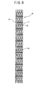
- Fig. 8 shows the tubular body, composed of a plurality of ring members, which is used as the implantable tubular device of the present invention with solid lines.
- Fig. 8 also shows a frame structure formed by removing the portion of the prepared tubular body other than the portion thereof that is to be formed as the implantable tubular device with broken lines.
- the tubular body 30 is produced by directly or indirectly connecting a plurality of ring members 23 disposed parallel with one another.
- the tubular body 30 has a plurality of annular deformable portions 17 formed between the adjacent ring members 23.
- a plurality of the deformable portion 17 are formed in connection portions 18 of the adjacent ring members 23 by connecting the ring members 23 to each other in the axial direction of a stent 30.
- Each deformable portion 17 is endless and annular.
- the ring members 23 adjacent to each other in the axial direction of the stent may be connected to each other directly (direct connection) by welding or the like or indirectly (indirect connection) through other member having a high flexibility.
- the entire adjacent surfaces of the ring members 23 do not necessarily have to be connected to each other but a part of the adjacent surfaces thereof can be connected to each other.
- the thickness of the deformable portion 17 does not necessarily have to be smaller than the diameter of the ring member 23, provided that the implantable tubular device can deform (flex) easily, with the deformable portion acting as the point of origin of the deformation.
- the thickness of the deformable portion 17 may be almost equal to the diameter of the ring member 23 by interposing other member between the adjacent ring members 23.
- the tubular body 30 has a diameter favorably 0.8 to 1.8 mm and more favorably 1.0 to 1.6 mm.
- the axial length of the tubular body is favorably 3 to 50mm and more favorably 5 - 30mm.
- a wire material forming the ring member 23 has a diameter favorably 0.01 to 0.2mm and more favorably 0.05 to 0.1mm.
- the interval between the adjacent ring members is favorably 0 to 0.5mm and more favorably 0 - 0.1mm. It is preferable to make the ring member of a material similar to the material for the stent 1.
- the method of shaping the implantable tubular device in other words, as the method of producing the frame structure by removing the portion of the prepared tubular body other than the portion thereof which is to be formed as the device, etching method known as photo-fabrication, using a mask and chemicals; electric discharge machining using a die; mechanical machining or laser processing method can be used.
- the implantable tubular device of this embodiment can be easily bent from the deformable portion which is formed at the connection portion of the adjacent ring members 23. Thus the implantable tubular device can pass through a bent portion of the human body.
- the balloon expandable stent has been described in the embodiment. But the present invention is applicable to the self-expandable stent.
- the implantable tubular device may carry a medicine or a bioprosthetic material(in other words, material originated inorganism or biosynthesis material). At least one part of the outer surface of the device may be coated with a coating material made of a biocompatible material, a biodegradable material or synthetic resin. At least the outer surface of the deformable portion may be entirely coated with the coating material made of the biocompatible material, the biodegradable material or the synthetic resin.
- Fig. 10 is a front view of an implantable device according to still another embodiment of the present invention.
- Fig. 11 is a partly enlarged view of the device shown in Fig. 10.
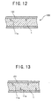
- Fig. 12 is a sectional view taken along a line A-A of Fig. 11.
- An implantable device 100 of the embodiment has a body 1 and a coating material 101 coating the implantable tubular device.
- the body 1 of the implantable tubular device of the present invention is formed as a substantial tubular body and has a deformable portion formed on a peripheral surface thereof, with the deformable portion forming a predetermined angle with the axial direction of the device.
- At least one part of the outer surface of the implantable tubular device of this embodiment is coated with a coating material made of an biocompatible material, an biodegradable material or synthetic resin.
- At least the outer surface of the deformable portion is entirely coated with the coating material made of the biocompatible material, the biodegradable material or the synthetic resin. More specifically, the entire device is coated with the coating material made of the biocompatible material, the biodegradable material or the synthetic resin.
- the body of the implantable tubular device 1 is formed as a substantial tubular body.
- the body of the implantable tubular device 1 has a diameter so set that it can be inserted into a lumen in the human body and can dilate radially upon application of a force acting radially outwardly from the interior of the tubular body.
- the body of the implantable tubular device has a plurality of wavy annular members each formed of a wavy element and arranged in the axial direction thereof; and connection portions each connecting the adjacent wavy annular members to each other in the axial direction thereof.
- the wavy annular member has the deformable portion formed on a bent portion thereof not connected to the other wavy annular members in such a way that the deformable portion crosses the wavy annular member.
- the implantable tubular device of all of the above-described embodiments can be used.
- the depth of the groove 11a forming the deformable portion is not definite but different according to the diameter and thickness of the stent.
- the depth of the groove 11a is favorably 1 - 99% of the thickness of the device and more favorably 5 - 50% thereof.
- the implantable tubular device of this embodiment has a coating material formed on the body thereof.
- the coating material 101 coats the entire surface (outer surface and inner surface) of the body 1 of the device. But the coating material 101 may coat a part of the outer surface of the body 1 or only the outer surface of the deformable portion.
- the coating material 101 consists of the biocompatible material, the biodegradable material or the synthetic resin.
- the following synthetic resins can be used to form the coating material 101: ethylene-vinyl acetate copolymer, polyester, silicone rubber (RTV rubber), thermoplastic polyurethane, fluorine resin (for example, PTFE, ETFE, thermoplastic fluorine resin), polyolefin (for example, polyethylene, polypropylene, low-density polyethylene, low-density polypropylene), polyester, polycaprolactone, polyvinyl acetate, polycarbonate, polyimide carbonate, aliphatic polycarbonate, and mixtures thereof.
- fluorine resin for example, PTFE, ETFE, thermoplastic fluorine resin
- polyolefin for example, polyethylene, polypropylene, low-density polyethylene, low-density polypropylene
- polyester polycaprolactone
- polyvinyl acetate polycarbonate
- polyimide carbonate polyimide carbonate
- aliphatic polycarbonate aliphatic polycarbonate
- biocompatible materials can be used to form the coating material 101, provided that platelets do not attach thereto easily and that they do not stimulate tissue: saccharide, silicone, mixture or block copolymer of polyether-type polyurethane and dimethyl silicon, polyurethane such as segmented polyurethane, polyacrylamide, polyethylene oxide, polyethylene carbonate, polycarbonate such as polypropylene carbonate, polymethoxy ethyl acrylate, polyhydroxy ethyl methacrylate, copolymer of hydroxy ethyl methacrylate and styrene (for example, HEMA-St-HEMA block copolymer), and fibrin.
- saccharide silicone, mixture or block copolymer of polyether-type polyurethane and dimethyl silicon
- polyurethane such as segmented polyurethane
- polyacrylamide polyethylene oxide
- polyethylene carbonate polycarbonate such as polypropylene carbonate
- polymethoxy ethyl acrylate polyhydroxy ethy
- biodegradable materials can be used to form the coating material 101, provided that they are decomposed enzymatically or non-enzymatically and a decomposed matter is not poisonous: polylactic acid, polyglicolic acid, polylactic acid-polyglicolic acid copolymer, polycaprolactone, polylactic acid-polycaprolactone copolymer, polyhydroxybutyric acid, polymalic acid, poly ⁇ -amino acid, collagen, gelatin, laminin, heparan sulfate, fibronectin, vitronectin, chondroitin sulfate, hyaluronic acid, chitin, and chitosan.
- the deformable portion can be reinforced with the coating material 101 coating at least the outer surface of the deformable portion 11. Further even though the body 1 of the device is broken at the deformable portion 11, the coating material prevents a broken portion from separating from the body 1.
- the thickness of the coating material 101 is favorably 0.1 - 100 ⁇ m and more favorably 5 ⁇ m - 50 ⁇ m, although its thickness is different according to the coating material that is used.
- the coating material is formed on the body of the device by preparing a solution in which a solvent dissolving a coating material-forming material therein without modifying it, bringing a portion of the body of the device on which the coating material is to be formed into contact with the solution, and removing the solvent.
- the body of the device can be brought into contact with the solution by immersing the body in the solution or applying the solution to the body.
- the implantable tubular device 100 shown in Figs. 10 and 11 has the coating material 101 coating the outer surface including the outer surface of the deformable portion 11 of the body 1 of the device and the inner surface of the body 1 thereof.
- the coating material-forming material fills into the groove 11a forming the deformable portion 11.
- the coating material-forming material filled into the groove 11a allows the deformable portion to be reinforced without preventing a large amount of deformation of the deformable portion and also allows the coating material to adhere to the body 1 of the device firmly. Thus it is possible to prevent the coating material from separating from the body 1.
- the portion of the coating material 101 filling into the groove is thicker than other portions of the coating material 101. Therefore, if the body 1 of the device is broken at the deformable portion 11 (groove 11a) in an implanting operation, the coating member is hardly broken. Thus even though the deformable portion 11 is broken, it is possible to prevent a broken portion from separating from the body 1.
- the implantable tubular device having the groove 11a forming the deformable portion on the outer and inner surfaces of the body thereof may be used. In this case, as shown in Fig. 13, it is preferable to penetrate the coating material-forming material into the groove 11a forming the deformable portion on the outer and inner surfaces of the body of the device.
- the body of the implantable tubular device is allowed to undergo a preferable deformation in the case where the body has the groove 11a forming the deformable portion on the outer and inner surfaces of the body. Further the penetration of the coating material-forming material into the groove 11a allows the deformable portion to be reinforced without preventing a large amount of the deformation of the deformable portion and also allows the coating material to adhere to the body 1 of the device firmly. Thus it is possible to prevent the coating material from separating from the body 1. Furthermore because the portion of the coating material 101 into which the coating material-forming material penetrates is thicker than other portions of the coating material 101. Therefore, if the body 1 of the implantable tubular device is broken at the deformable portion 11 (groove 11a) in an implanting operation, the coating member is hardly broken.
- the body of the implantable tubular device may carry a medicine or a bioprosthetic material(in other words, biosynthesis material, material originated inorganism).
- a medicine or a bioprosthetic material in other words, biosynthesis material, material originated inorganism
- the implantable tubular device has the coating material carrying the medicine or the bioprosthetic material(in other words, material originated inorganism). But it is possible that the implantable tubular device does not have the coating material and instead carries the medicine or the bioprosthetic material(in other words, material originated inorganism) directly.
- the medicine or the bioprosthetic material(in other words, material originated inorganism) is contained in the layer of the coating material or applied to the surface thereof.
- the coating material may be porous.
- a mixture of the medicine and the biodegradable material is essentially applied to the outer surface of the body of the device.
- the mixture of the medicine and the biodegradable material is applied to the entire surface thereof.
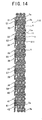
- Fig. 14 is a front view of an implantable device according to still another embodiment of the present invention.
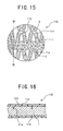
- Fig. 15 is a partly enlarged view of the implantable tubular device shown in Fig. 14.
- Fig. 16 is a sectional view taken along a line B-B of Fig. 15.
- the implantable tubular device can carry the following medicines: medicine for preventing intimal hyperplasia, carcinostatic agent, immunosuppressor, antibiotic, antirheumatic, antithrombotic drug, HMG-CoA reductase inhibitor, ACE inhibitor, calcium antagonist, anti-hyperlipidemia agent, anti-inflammatory agent, integrins inhibitor, antiallergic agent, antioxidant, GP II b III a antagonist, retinoids, flavonoids, carotenoids, lipid-improving agent, DNA-synthesis inhibitor, tyrosine kinase inhibitor, antiplatelet agent, vascular smooth muscle cell proliferution inhibitor, bioprosthetic material(in other words, material originated inorganism), interferon, and epithelial cell formed by genetic engineering. Mixtures each containing two or more of these agents may be used.
- carcinostatic agents are preferable:vincristine, vinblastine, vindesine, vindesine sulfate, irinotecan, irinotecan hydrochloride, pirarubicin, pirarubicin hydrochloride, paclitaxel(PTX), docetaxel, docetaxel hydrate, and methotrexate(MTX).
- immunosuppressors are preferable: sirolimus, tacrolimus, tacrolimus hydrate, azathioprine(AZP), ciclosporin(CYA), cyclophosphamide, mycophenolate mofetil, gusperimus hydrochloride, and mizoribine.
- antibiotics are preferable: mitomycin, adriamycin(ADM), doxorubicin, doxorubicin hydrochloride(DXR), actinomycin, actinomycin D, daunorubicin, daunorubicin hydrochloride, idarubicin, idarubicin hydrochloride(DNR), pirarubicin, pirarubicin hydrochloride(THP), aclarubicinn, aclarubicin hydrochloride(ACR), epirubicin, epirubicin hydrochloride(EPI), peplomycin, peplomycin sulfate(PEP), and zinostatin stimalamer.
- methotrexate MTX
- sodium thiomalate sodium thiomalate
- penicillamine sodium thiomalate
- lobenzarit lobenzarit disodium.
- anti-thrombotic drugs are preferable: heparin, aspirin, antithrombin preparation, ticlopidine, ticlopidine hydrochloride and hirudin.
- HMG-CoA reductase inhibitors are preferable: cerivastatin, cerivastatin sodium, atorvastatin, atorvastatin calcium, nisvastatin, itavastatin, fluvastatin, fluvastatin sodium, simvastatin, lovastatin, and pravastatin, pravastatin sodium.
- ACE inhibitors are preferable: quinapril, quinapril hydrochloride, perindopril erbumine, trandolapril, cilazapril, temocapril, temocapril hydrochloride, delapril, delapril hydrochloride, enalapril maleate, lisinopril, and captopril.
- nifedipine nilvadipine, diltiazem, diltiazem hydrochloride, benidipine, benidipine hydrochloride, and nisoldipine.
- probucol is preferable.
- tranilast is preferable.
- retinoids all trans retinoic acid is preferable.
- catechins is preferable. Particularly, Epigallocatechin gallate, anthocyanins, proanthocyanidin, lycopene, and ⁇ -carotin are preferable.
- tyrosine kinase inhibitors genistein, erbstatin, and Tyrphostins are preferable.
- steroids such as dexamethasone and prednisolone are preferable.
- bioprosthetic materials (in other words, materials originated inorganism) are preferable: EGF (epidermal growth factor), VEGF (vascular endothelial growth factor), HGF (hepatocyte growth factor), PDGF (platelet derived growth factor), and bFGF (basic fibroblast growth factor).
- An implantable device 110 shown in Figs. 14 through 16 has the coating material 111 coating the outer surface including the outer surface of the deformable portion 11 of the body 1 of the device and the inner surface of the body 1 thereof.
- the coating material contains the medicine or the bioprosthetic material(in other words, material originated inorganism) or has the medicine or the bioprosthetic material on its surface.
- the implantable tubular device 110 of the embodiment has the coating material 111 made of a mixture of a medicine 112.
- the coating material-forming material is in penetration into the groove 11a forming the deformable portion 11.
- the penetration of the coating material-forming material into the groove 11a allows the deformable portion to be reinforced without preventing a large amount of deformation of the deformable portion and also allows the coating material to adhere to the body 1 of the device firmly.
- the coating material from separating from the body 1.
- the portion of the coating material 111 into which the coating material-forming material penetrates is thicker than other portions of the coating material 111.
- the coating member is hardly broken.
- the deformable portion 11 is broken, it is possible to prevent a broken portion from separating from the body 1.
- the implantable tubular device 110 of the embodiment has the coating material 111, composed of a mixture of the biodegradable material and the medicine 112, coating the inner and outer surfaces thereof.
- the biodegradable material decomposes and the medicine is gradually discharged from the coating material. Thereby the effect of the medicine can be obtained continuously for a certain period of time.
- the medicine or the bioprosthetic material(in other words, material originated inorganism) is carried by the body of the implantable tubular device by preparing a mixed solution containing a solvent which can disperse the medicine or the bioprosthetic material(in other words, material originated inorganism) therein without modifying them and which has adherence to the body of the implantable tubular device; and bringing a portion of the body of the implantable tubular device on which the medicine or the bioprosthetic material(in other words, material originated inorganism) is to be carried into contact with the mixed solution.
- the body of the implantable tubular device can be brought into contact with the mixed solution by immersing the body thereof in the mixed solution or applying the mixed solution to the body thereof.
- the implantable tubular device may have the coating material 111 made of the biocompatible material, the biodegradable material or the synthetic resin formed on its surface and further the medicine 112 or the bioprosthetic material(in other words, material originated inorganism) held on the surface of the coating material 111.
- the implantable tubular device can have the coating material 111 made of the biocompatible material, the biodegradable material or the synthetic resin on its surface and carries the medicine 112 or the bioprosthetic material(in other words, material originated inorganism) on the surface of the coating material 111 as follows:
- the coating material is formed on the body of the implantable tubular device by preparing a solution in which a solvent dissolving a coating material-forming material therein without modifying it, bringing a portion of the body of the implantable tubular device on which the coating material is to be formed into contact with the solution, and removing the solvent.
- the body of the implantable tubular device can be brought into contact with the solution by immersing the body thereof in the solution or applying the solution to the body thereof.
- a solution consisting of water in which the medicine or the bioprosthetic material(in other words, material originated inorganism) is dissolved or dispersed is prepared.
- the medicine or the bioprosthetic material(in other words, material originated inorganism) does not have adhesion to the coating material
- the medicine or the bioprosthetic material(in other words, material originated inorganism) is added to a solution containing a material which can disperse the medicine or the bioprosthetic material(in other words, material originated inorganism) and which has adhesion to the coating material to form a mixed solution.
- a portion of the body of the implantable tubular device on which the medicine or the bioprosthetic material(in other words, material originated inorganism) is to be held is brought into contact with the mixed solution.
- the body of the implantable tubular device can be brought into contact with the mixed solution by immersing the body thereof in the mixed solution or applying the mixed solution to the body thereof.
- Grooves were formed on the entire peripheral surface of a pipe made of SUS 316L having a diameter of 1.44mm, a thickness of 0.095mm by utilizing a laser machining method (YAG laser model SL116E manufactured by NEC). The interval between the adjacent spiral grooves was 0.1mm. The depth of the groove was about 0.02mm. In the laser machining method, the output of the laser was 2.35 kW, and the processing speed was 50mm/mimute.
- the metal pipe having the spiral groove formed on its surface was mounted on a jig equipped with a rotating motor and a fastening mechanism to prevent run-out of the metal pipe.
- the jig was set on a numerically controllable XY table.
- the XY table and the rotating motor were connected to a personal computer such that an output of the personal computer was transmitted to a numerical controller of the XY table and the rotating motor.
- a development drawing representing the stent having the structure shown in Fig. 2 was inputted to the personal computer storing a design software.
- the XY table and the rotating motor were driven in accordance with design data outputted from the personal computer.
- the pipe was irradiated with a laser beam to machine the pipe into a stent structure having the configuration shown in Fig. 1.
- the laser machining condition for the metal pipe current value was 25 A, an output was 1.5 W, and a drive speed was 10 mm/min.
- the machine is not limited to the above-described system but it is possible to use a laser marker of the galvanometer system to be driven by a laser machining device.
- a stent structure having the configuration shown in Fig. 1 was prepared in this manner.
- the stent structure was dipped in a stainless steel chemical polishing solution at about 98°C for about 10 minutes to chamfer and chemically polish the stent structure.
- the chemical polishing solution used in example 1 contained a mixture of hydrochloric acid and nitric acid serving as a main component, an organic sulfur compound, and a surface active agent.
- the chemical polishing solution is commercially available as Sunbit 505 from Sanshin Chemical Industry K.K.
- the stent of the present invention having the configuration shown in Figs. 1 through 3 was prepared.
- the stent had an entire length of 20 mm and an outer diameter of 1.4 mm.
- the width of a portion constituting a wavy element (wavy annular member) and a joining portion was 0.12 mm.
- a connection portion had a width 0.03mm and a length of 0.1mm.
- the stent had a thickness of about 0.08mm.
- the stent of the comparison example was formed in a way similar to that of the example 1.
- an undilated stent 90 was fixed to a fixing device 91 at a position thereof 10mm spaced from the rear end thereof.
- a portion of the stent 90 in the vicinity of the front end thereof was pressed downward with a penetrator 92 to measure a load applied thereto when the front end thereof descended 2mm.
- Table 1 Load (g) Example 1 0.77 Comparison example 2.60
- the load of the groove-unprovided stent of the comparison example was 2.60g, whereas that of the groove-provided stent (example 1) was 0.77g which was much smaller than 2.60g. This indicates that owing to the formation of the groove on the stent, the stent is allowed to have a much higher flexibility.
- a mixed solution was formed from a solution containing 5mg of cerivastatin sodium which is an HMG-CoA reductase inhibitor dissolved in 1ml of ethanol and a solution containing 40mg of polylactic acid dissolved in 4ml of dichloromethane.
- the stent of example 1 was sprayed with the mixed solution of the polylactic acid containing the cerivastatin sodium. That is, the entire outer surface of the stent having the deformable portion was coated with the biodegradable material containing the medicine.
- a solution containing 40mg of polylactic acid dissolved in 4ml of dichloromethane was prepared.
- the stent of example 1 was immersed in the solution. After the stent was pulled upward, it was dried.
- the stent coated with the polylactic acid was prepared. That is, the entire surface of the stent having the deformable portion was coated with the biodegradable material.
- a mixed solution containing 5mg of EGF which was used as a bioprosthetic material(in other words, material originated inorganism) and 40mg of gelatin dissolved in 4ml of water was prepared.
- the stent of example 1 was sprayed with the mixed solution of the gelatin containing the EGF. That is, the entire outer surface of the stent having the deformable portion was coated with the biodegradable material containing the bioprosthetic material(in other words, material originated inorganism).
- paclitaxel(PTX) which is a carcinostatic agent and 40mg of silicone were dissolved in 4ml of cyclohexane.
- the stent of example 1 was sprayed with the solution of the silicone containing the paclitaxel. That is, the entire outer surface of the stent having the deformable portion was coated with the biocompatible material containing the medicine.
- a solution containing 40mg of silicone dissolved in 4ml of cyclohexane was prepared.
- the stent of example 1 was immersed in the solution. After the stent was pulled upward, it was dried. That is, the stent coated with the silicone was prepared.
- the surface of the stent was sprayed with a solution containing 5mg of cerivastatin sodium dissolved in 1ml of ethanol.
- the surface of the stent coated with the silicone was coated with the cerivastatin sodium. That is, the entire outer surface of the stent having the deformable portion was coated with the biocompatible material coated with the medicine.
- an undilated stent 90 was fixed to a fixing device 91 at a position thereof 10mm spaced from the rear end thereof.
- a portion of the stent 90 in the vicinity of the front end thereof was pressed downward with a penetrator 92 to measure a load applied thereto when the front end thereof descended 2mm.
- Table 2 Load (g) Example 2 1.83
- Example 3 1.79
- Example 4 1.67
- Example 5 2.03
Abstract
Description
- The present invention relates to an implantable tubular device such as a stent to be implanted in human body such as a blood vessel, a bile duct, a trachea, an esophagus, an ureter, and internal organs to improve a stenotic lesion or a total occlusion formed in the lumens.
- To cure various diseases that are caused when the blood vessel or lumens are stenosis or occlusion, the stent which is a tubular-shaped medical appliance is implanted at the stenotic lesion or the total occlusion to expand them and secure the lumen thereof.
- The stents are classified into self-expandable stents and balloon expandable stents, depending on the function thereof and the implantation method. Balloon expandable stents have no dilating function. After a balloon expandable stent is inserted into a target lesion, a balloon expandable inside the stent in an extent almost equal to the normal diameter of the lumen of the target lesion is inflated to dilate (plastic deformation) the stent by the inflation force of the balloon so that the stent comes in close contact with the inner surface of the target lesion.
- To deliver the stent to a desired portion of a human body, it is necessary that the mounted balloon and the stent are flexible. For improving the flexibility of an approximately tubular stent having a plurality of annular units disposed axially and joining portions joining adjacent annular units to each other, a known method comprises reducing the number of joining portions (articulation) disposed between the adjacent annular units (i.e. mono-link stent).
- However, this method is incapable of improving the flexibility of the annular unit. Therefore, there is a demand for the development of an implantable device, such as a stent to be implanted in lumens, which is flexible so that it can pass smoothly through a curved portion of the human body.
- An implantable tubular device as defined in the preamble of
claim 1 is disclosed inWO 94/17754 -
WO 01/00112 - The present invention has been made to solve the above-described problems. Therefore, it is an object of the present invention to provide an implantable tubular device, for example, a stent, having a deformable portion to improve the flexibility of an annular unit of the device so that the device can pass easily through a bent portion of a human body
- The object described above is attained by an implantable tubular device formed as a substantially tubular body having a diameter so set that said device can be inserted into a lumen of a human body and capable of dilating radially upon application of a force acting radially outwardly from an interior of said tubular body, which device comprises a plurality of wavy annular members each formed of a wavy element and arranged in an axial direction of said device and connection portions each connecting said wavy annular members to each other in the axial direction of said device.
- Each of said wavy annular members has a plurality of deformable portions each consisting of a groove having a width of 1 µm - 100 µm provided on a surface of said device. Each of said wavy annular members has a bent portion which is not connected to the other wavy annular members in such a way that said deformable portions cross said wavy annular member including said bent portion.
-
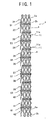
- Fig. 1 is a front view of an implantable tubular device according to an embodiment of the present invention.
- Fig. 2 is a development view of the implantable tubular device of Fig. 1.
- Fig. 3 is a partly enlarged front view of the implantable tubular device of Fig. 1.
- Fig. 4 is a front view of an implantable tubular device according to another embodiment of the present invention.
- Fig. 5 is a development view of the implantable tubular device of Fig. 4.
- Fig. 6 is a partly enlarged front view of the implantable tubular device of Fig. 4.
- Fig. 7 is an explanatory view for describing an implantable tubular device of another embodiment of the present invention.
- Fig. 8 is an explanatory view for describing an implantable tubular device of still another embodiment of the present invention.
- Fig. 9 is an explanatory view for describing a method of measuring flexibility of the implantable tubular device of the present invention.
- Fig. 10 is a front view of an implantable tubular device according to still another embodiment of the present invention.
- Fig. 11 is a partly enlarged view of the implantable tubular device shown in Fig. 10.
- Fig. 12 is a sectional view taken along a line A-A of Fig. 11.
- Fig. 13 is an explanatory view for describing an implantable tubular device according to still another embodiment of the present invention.
- Fig. 14 is a front view of an implantable tubular device according to still another embodiment of the present invention.
- Fig. 15 is a partly enlarged view of the implantable tubular device shown in Fig. 14.
- Fig. 16 is a sectional view taken along a line B-B of Fig. 15.
- Fig. 17 is an explanatory view for describing an implantable tubular device according to still another embodiment of the present invention.
- An embodiment of the implantable tubular device of the present invention (hereinafter referred to as mostly "device") will be described below with reference to the drawings.
- An implantable
tubular device 1 of the present invention to be implanted in a lumen is formed substantially tubular and has an easy deformable portion formed on a peripheral surface thereof, with the deformable portion forming a predetermined angle with respect to the axial direction of thedevice 1. It can be said that the deformable portion is a weak portion or a thin portion. The deformable portion is easy to deform in comparison with a remainder part of the device - Because the implantable
tubular device 1 of the present invention has the deformable portion, the implantable tubular device has a high flexibility and can pass through a bent or curved portion of a human body easily and leaves little hysteresis of deformation which occurs at the time of insertion thereof in the human body. - The implantable tubular device of the present invention to be implanted in lumens of the human body includes a stent and a stent graft that is used to improve a stenotic lesion or a total occlusion formed in the lumens such as a blood vessel, a bile duct, a trachea, an esophagus, an ureter, and the like.
- The deformable portion includes a portion which is thinner than the other portion (undeformable portion) of the device and thus more flexible than the other portion; a portion which has pores and is thus more flexible than the other portion (undeformable portion) of the device; or a portion which is made of a material having a lower strength than the other portion (undeformable portion) of the device and is thus more frail than the other portion. The deformable portion of the implantable
tubular device 1 shown in Fig. 1 forms a predetermined angle with respect to the axial direction of the device. Accordingly, the implantable tubular device can be curved easily along a curved portion formed in a lumen. The deformable portion is so formed that it makes a predetermined angle with respect to the axial direction of the device. In other words, the deformable portion is so formed that it is not parallel with the axial direction of the device. Therefore, when the implantable tubular device is inserted into the human body and diametrically enlarged, the deformable portion does not cause the device to be broken. - An embodiment of the implantable tubular device of the present invention will be described below with reference to Fig. 1.
- The implantable tubular device of the present invention is formed as a substantial tubular body. The implantable
tubular device 1 has a diameter so set that it can be inserted into a lumen in the human body and can dilate radially upon application of a force acting radially outwardly from the interior of the tubular body. The implantable tubular device has a plurality of wavy annular members each formed of a wavy element and arranged in the axial direction thereof; and connection portions each connecting the adjacent wavy annular members to each other in the axial direction thereof. The wavy annular member has the deformable portion formed on a bent portion thereof not connected to the other wavy annular members in such a way that the deformable portion crosses the wavy annular member. - In this embodiment, the implantable tubular device consists of a
stent 1. - The implantable tubular device (stent) 1 is a so-called balloon expandable stent. That is, the
stent 1 is formed as substantially tubular body and has a diameter so set that thestent 1 can be inserted into the human body. Thestent 1 can dilate radially outwardly upon application of a force acting radially outwardly from the interior of the tubular body. - The
stent 1 has a frame structure. Thestent 1 of the embodiment includesannular units annular member 2a annularly formed of a wavy element (preferably having no edge); a second wavyannular member 2b disposed in the axial direction of thestent 1 in such a way that a mountain thereof is proximate to a valley of the first wavyannular member 2a and annularly formed of a wavy element (preferably having no edge); and a plurality of connection portions 4 (preferably having no edge) connecting the valley of the first wavyannular member 2a and the mountain of the second wavyannular member 2b to each other. Thestent 1 further includes joiningportions stent 1 and each connecting the wavy elements (the second wavyannular member 2b and the first wavyannular member 2a) of the adjacent annular units to each other. It can be said that thestent 1 is a tubular body constructed of a plurality of annular units connected to each other with the joining portions. In thestent 1 of the embodiment, it can be also said that one annular unit is annularly formed of a plurality of rhombic elements annularly arranged. - As shown in Fig. 1 and Fig. 2 which is a developed view of Fig. 1, each of the first wavy
annular member 2a and the second wavyannular member 2b is constructed of an tubularly continuous endless wavy material having six mountains and valleys. Preferably, the number of the mountains (or valleys) of the tubular bodies is four to seven. Each of a plurality of short connection portions connects the valley of the second wavy annular member and the mountain of the second wavyannular member 2b disposed in the axial direction of thestent 1 in such a way that the mountain thereof is proximate to the valley of the first wavyannular member 2a. In this manner, one annular unit is constructed. In the embodiment, theconnection portions 4 connect all the valleys of the second wavy annular member and all the mountains of the second wavyannular member 2b to each other. One annular unit has six (equal to the number of mountains or valleys of the tubular body)connection portions 4. - It is preferable that the material for the
stent 1 has a certain degree of compatibility with an organism. For example, it is possible to use stainless steel, tantalum or tantalum alloys, platinum or platinum alloys, gold or gold alloys, and cobalt base alloys. It is preferable to plate the stent with a noble metal such as gold and platinum after the stent is fabricated into a final shape. As the stainless steel, SUS 316L most corrosion-resistant of the above metals can be preferably used. - It is preferable to anneal the
stent 1 after it is fabricated into the final shape. Annealing improves the flexibility and plasticity of the entire stent so that the stent can be effectively implanted in a curved blood vessel. As compared with a non-annealed stent, the annealed stent has a lower force of restoring to an original state after it is dilated and has a lower force of restoring to an original linear state when it is dilated at a curved portion of a blood vessel. This minimizes physical stimulation to the inner wall of the curved blood vessel, thus reducing the cause of a recurrence of stenosis. The stent is preferably annealed by heating it to 900 to 1200 °C in an inert gas atmosphere (e.g., a mixture gas of nitrogen and hydrogen) so that no oxide film is formed on the surface of the stent and then slowly cooling it. - The
stent 1 has a diameter of favorably 0.8 to 1.8 mm and more favorably of 1.0 to 1.6 mm in an undilated state. Thestent 1 has a length favorably of 9 to 40 mm in an undilated state. The length of each of the wavyannular members annular units 31 through 42 is favorably 1.5 - 4.0 mm and more favorably 2.0 - 3.0 mm. The length of eachconnection portion 4 is favorably 0.01 - 0.5 mm. The number of theannular units 31 through 42 is 3 to 50. The constituent elements (annular member) of the adjacent annular units have an axial overlap length of about 0.5 to 1 mm. The distance between the center of one annular unit and that of the annular unit adjacent thereto is preferably 1.3 to 2.5 mm. The length of each of the joiningportions portions 51 through 61 with respect to the axis of the stent is favorably 0° to 30° and more favorably 5° to 25°. - The thickness of each of the wavy
annular members stent 1 and that of each of the joiningportions annular members portions connection portion 4 of thestent 1 is favorably 0.05 - 0.12 mm and more favorably 0.06 - 0.10 mm. The width of theconnection portion 4 of thestent 1 is favorably 0.01 - 0.05 mm and more favorably 0.02 to 0.04 mm. The sectional area of theconnection portion 4 is favorably 1/50 to 1/2 of that of the other parts (annular member and joining portion) and more favorably 1/20 to 1/10 of that of the other parts. - The
stent 1 has the deformable portion formed on the wavy annular member constructing thestent 1. More specifically, the deformable portion is formed on a bent portion of the wavy annular member not connected to the other wavy annular members in such a way that the deformable portion crosses the wavy annular member. Therefore, the free bent portion of the wavy annular member not connected to the other wavy annular members is allowed to deform easily. Further, a deformation hysteresis that occurs when thestent 1 is inserted into the human body does not remain in the free bent portion. The deformable portion is entirely formed on thestent 1 to deform the entire stent easily. - The deformable portion is formed on the bent portion of the wavy annular member not connected to the other wavy annular members in such a way that the deformable portion crosses the wavy annular member. More specifically, when the deformable portion is viewed in the axial direction of the wavy annular member, namely, in the axial direction of the stent (device), the deformable portion is formed on the bent portion of the wavy annular member not connected to the other wavy annular members in such a way that the deformable portion crosses the wavy annular member. That is, the deformable portion forms 20 - 90° and favorably 70 - 90° with the axial direction of the device. In the embodiment, the deformable portion is almost orthogonal (90° ) to the axial direction of the device.
- The deformable portion is formed in such a way that when the deformable portion is prolonged, it continuously goes around the periphery of the device. That is, when the deformable portion is prolonged, it forms an endless annular configuration. Further the deformable portions are formed on the bent portion of the wavy annular member in such a way that they are substantially parallel with one another. Thereby the implantable tubular device has substantially annular grooves. Thus the implantable tubular device is prevented from being bent in a particular direction. That is, the implantable tubular device is capable of easily flexing in any directions.
- The depth of a
groove 11a is not definite but different according to the diameter and thickness of the stent. The depth of thegroove 11a is favorably 5 - 50% of the thickness of the device and more favorably 10 - 20% thereof. The width of thegroove 11a is favorably 1µm - 100µm and more favorably 5µm - 50µm. It is preferable that the interval between the adjacent deformable portions (the interval between the grooves, namely, the interval between the grooves in the axial direction of stent) is much shorter than the axial length of the annular unit. Thus it is preferable that the interval between the adjacent deformable portions is 1/80 - 1/8 of the axial length of the annular unit to improve the flexibility of the annular unit. In the case of thestent 1 of the embodiment, the interval between the adjacent grooves of thestent 1 is favorably 0.01 - 1mm and more favorably 0.05 - 0.5mm. The deformable portions (groove 11a) 11 of thestent 1 of the embodiment are formed at regular intervals but may be formed at irregular intervals or at regular intervals in one region and at irregular intervals in other region. - The interval between the adjacent grooves in the axial direction of the stent does not necessarily have to be uniform. For example, the interval between the adjacent grooves at both axial ends of the
stent 1 may be different from that between the adjacent grooves at the axial central portion thereof to vary the flexibility of thestent 1, depending on a portion thereof. More specifically, the interval between the adjacent grooves may be short at both axial ends of thestent 1 and long at the axial central portion thereof to allow both axial ends of thestent 1 to be more flexible than the axial central portion thereof. - The
groove 11a of the embodiment is formed on only the outer surface of the stent (device) 1. But thegroove 11a may be formed on only the inner surface thereof or on both the outer and inner surfaces thereof. In the case where thegroove 11a is formed on both the outer and inner surfaces of the substantially tubular body, it is not preferable to form the grooves on concentric circles of the tubular body to prevent the groove formed on the outer surface thereof and the groove formed on the inner surface thereof from being coincident with each other in the axial direction of the tubular body. Thereby the deformable portion does not cause a low-strength portion to be formed on the device. - The implantable tubular device (stent) is formed as a frame structure by removing a portion of a tubular body (metal pipe) other than a portion thereof which is to be formed as a frame structure. For example, the stent is formed by removing an unnecessary portion from a metal pipe by using an etching process, known as photo-fabrication, using a mask and chemicals; electric discharge machining; mechanical machining using a die; or laser machining method. After the frame structure is prepared, it is preferable to polish the edge of the frame structure by using chemical polishing or electro-polishing.
- The method of processing the
groove 11a (deformable portion 11) will be described below. - The
groove 11a may be formed after a cylindrical member formed from the above-described forming material is processed into the shape of the stent; before the cylindrical member is processed into the shape of the stent; or at the time when the cylindrical member is processed into the shape of the stent. Thegroove 11a is formed by laser processing method of processing the groove by emitting laser to the cylindrical member, etching method using photoresist technique or mechanical machining. After thegroove 11a is formed, it is preferable to polish the surface of the groove by using chemical polishing or electro-polishing. - In the case where the groove is formed on the inner surface of the stent 1 (in the case where the deformable portion is formed from the inner surface of the stent 1), it is preferable to use a method of forming a thread groove on the inner surface of the cylindrical member by using a tap.
- In the above embodiment, the annular units are connected with each other with one joining portion, i.e., the stent of mono-link type has been exemplified. But the annular units may be connected with each other with a plurality of joining portions. That is, the stent of the present invention may be of link type.
- The deformable portion does not necessarily have to consist of the groove but may consist of a thin portion having a predetermined width.
- Another embodiment of the implantable tubular device of the present invention will be described below.
- Fig. 4 is a front view of a stent according to another embodiment of the present invention. Fig. 5 is a development view of the stent of Fig. 4. Fig. 6 is a partly enlarged front view of the stent of Fig. 4.
- The implantable tubular device of this embodiment is different from the above-described embodiment in that a
stent 10 and adeformable portion 13 of this embodiment are different from thestent 1 and thedeformable portion 11 of the above-described embodiment respectively. - In the
stent 10, thedeformable portion 13 is so formed that when the deformable portion is prolonged, a spiral is formed on the peripheral surface of the device. Preferably, the number of spirals is 1 - 500. In this embodiment, the number of spirals is 34. When a plurality of spirals are formed, the interval between adjacent spirals (grooves) in the axial direction of the stent is preferably 0.05 - 0.5mm. The inclination of the spiral with respect to the axial direction of the stent is preferably 60 - 80°. - The depth of a
groove 13a is not definite but different according to the diameter and thickness of the stent. The depth of thegroove 13a is favorably 5 - 50% of the thickness of the device and more favorably 10 - 20% thereof. The width of thegroove 13a is favorably 1µm - 100µm and more favorably 5µm - 10µm. - The inclination of the spiral formed by the groove with respect to the axial direction of the stent, in other words, the pitch between the adjacent spirals formed by the groove does not necessarily have to be equal to each other. For example, the pitch between the adjacent spirals at both axial ends of the
stent 10 may be different from that between the adjacent spirals at the axial central portion thereof to vary the flexibility of thestent 10, depending on a portion thereof. More specifically, the pitch between the adjacent spirals may be short at both axial ends of thestent 10 and long at the axial central portion thereof to allow both ends of thestent 10 to be more flexible than the axial central portion thereof. - The
groove 13a of the present invention is formed on only the outer surface of the stent (device) 10. But thegroove 13a may be formed on only the inner surface thereof or on both the outer and inner surfaces thereof. In the case where thegroove 13a is formed on both the outer and inner surfaces of the substantially tubular body, it is preferable to prevent the groove formed on the outer surface thereof and the groove formed on the inner surface thereof from being coincident with each other in the axial direction of the tubular body. Thereby the deformable portion does not cause a low-strength portion to be formed on the device. The deformable portion does not necessarily have to consist of the groove but may consist of a thin portion having a predetermined width. - The
deformable portion 13 of thestent 10 can be formed by the methods that are used to form the above-describeddeformable portion 11 of thestent 1. - In addition, the implantable tubular device of the present invention may be produced from a spiral deformable portion-provided tubular body formed by connecting axially adjacent coiled wire members to each other directly or indirectly. In this case, the implantable tubular device of the present invention is formed as a frame structure by removing a portion of the prepared tubular body other than a portion thereof which is to be formed as the device.
- Fig. 7 shows the tubular body, composed of the coiled wire member, which is used as the device of the present invention with solid lines. Fig. 7 also shows the frame structure formed by removing the portion of the tubular body other than the portion thereof which is to be formed as the implantable tubular device with broken lines.
- The tubular body is produced by directly or indirectly connecting adjacent
coiled wire members 21 to each other in the axial direction of the coil. The tubular body has the spiraldeformable portions 15. - The thickness of a
connection portion 16 of thetubular body 20 is formed smaller than the diameter of thewire member 21 to deform theconnection portion 16 more easily than the body of thewire member 21. Thewire members 21 adjacent to each other in the axial direction of the coil may be connected to each other directly (direct connection) by welding or the like or indirectly (indirect connection) through other member having a high flexibility. In the direct and indirect connections, the entire adjacent surfaces of thewire members 21 do not necessarily have to be connected to each other but a part of the adjacent surfaces thereof can be connected to each other. - The thickness of the
deformable portion 15 does not necessarily have to be smaller than the diameter of thewire member 21, provided that the implantable tubular device can deform (flex) easily, with the deformable portion acting as the point of origin of the deformation. For example, the thickness of thedeformable portion 15 may be almost equal to the diameter of thewire member 21 by interposing other member between theadjacent wire members 21. - The
tubular body 20 has a diameter favorably 0.8 mm to 1.8 mm and more favorably 1.0 mm to 1.6 mm. The axial length of the tubular body is favorably 3 mm to 50mm and more favorably 5 mm - 30mm. - The wire member has a diameter favorably 0.01 to 0.2mm and more favorably 0.05 to 0.1mm. The interval between the adjacent wire members is favorably 0 to 0.5mm and more favorably 0 - 0.1mm. It is preferable to make the wire member of a material similar to the material for the
stent 1. - As the method of shaping the implantable tubular device, in other words, as the method of producing the frame structure by removing the portion of the prepared tubular body other than the portion thereof which is to be formed as the device, etching method known as photo-fabrication, using a mask and chemicals; electric discharge machining using a die; mechanical machining or laser processing method can be used.
- The implantable tubular device of this embodiment can be easily bent from the deformable portion which is formed at the connection portion of the
adjacent wire members 21. Thus the implantable tubular device can pass smoothly through a bent portion of the human body. - Further the implantable tubular device of the present invention may be produced from an annular deformable portions-provided tubular body formed by directly or indirectly connecting ring members so disposed parallel to each other as to form a cylindrical shape. In this case, the implantable tubular device of the present invention is formed as a frame structure by removing a portion of the prepared tubular body other than a portion thereof which is to be formed as the device.
- Fig. 8 shows the tubular body, composed of a plurality of ring members, which is used as the implantable tubular device of the present invention with solid lines. Fig. 8 also shows a frame structure formed by removing the portion of the prepared tubular body other than the portion thereof that is to be formed as the implantable tubular device with broken lines.
- The
tubular body 30 is produced by directly or indirectly connecting a plurality ofring members 23 disposed parallel with one another. Thetubular body 30 has a plurality of annulardeformable portions 17 formed between theadjacent ring members 23. A plurality of thedeformable portion 17 are formed inconnection portions 18 of theadjacent ring members 23 by connecting thering members 23 to each other in the axial direction of astent 30. Eachdeformable portion 17 is endless and annular. - The
ring members 23 adjacent to each other in the axial direction of the stent may be connected to each other directly (direct connection) by welding or the like or indirectly (indirect connection) through other member having a high flexibility. In the direct and indirect connections, the entire adjacent surfaces of thering members 23 do not necessarily have to be connected to each other but a part of the adjacent surfaces thereof can be connected to each other. - The thickness of the
deformable portion 17 does not necessarily have to be smaller than the diameter of thering member 23, provided that the implantable tubular device can deform (flex) easily, with the deformable portion acting as the point of origin of the deformation. For example, the thickness of thedeformable portion 17 may be almost equal to the diameter of thering member 23 by interposing other member between theadjacent ring members 23. - The
tubular body 30 has a diameter favorably 0.8 to 1.8 mm and more favorably 1.0 to 1.6 mm. The axial length of the tubular body is favorably 3 to 50mm and more favorably 5 - 30mm. - A wire material forming the
ring member 23 has a diameter favorably 0.01 to 0.2mm and more favorably 0.05 to 0.1mm. The interval between the adjacent ring members is favorably 0 to 0.5mm and more favorably 0 - 0.1mm. It is preferable to make the ring member of a material similar to the material for thestent 1. - As the method of shaping the implantable tubular device, in other words, as the method of producing the frame structure by removing the portion of the prepared tubular body other than the portion thereof which is to be formed as the device, etching method known as photo-fabrication, using a mask and chemicals; electric discharge machining using a die; mechanical machining or laser processing method can be used.
- The implantable tubular device of this embodiment can be easily bent from the deformable portion which is formed at the connection portion of the
adjacent ring members 23. Thus the implantable tubular device can pass through a bent portion of the human body. - The balloon expandable stent has been described in the embodiment. But the present invention is applicable to the self-expandable stent.
- The implantable tubular device may carry a medicine or a bioprosthetic material(in other words, material originated inorganism or biosynthesis material). At least one part of the outer surface of the device may be coated with a coating material made of a biocompatible material, a biodegradable material or synthetic resin. At least the outer surface of the deformable portion may be entirely coated with the coating material made of the biocompatible material, the biodegradable material or the synthetic resin.
- Fig. 10 is a front view of an implantable device according to still another embodiment of the present invention. Fig. 11 is a partly enlarged view of the device shown in Fig. 10. Fig. 12 is a sectional view taken along a line A-A of Fig. 11.
- An
implantable device 100 of the embodiment has abody 1 and acoating material 101 coating the implantable tubular device. - The
body 1 of the implantable tubular device of the present invention is formed as a substantial tubular body and has a deformable portion formed on a peripheral surface thereof, with the deformable portion forming a predetermined angle with the axial direction of the device. At least one part of the outer surface of the implantable tubular device of this embodiment is coated with a coating material made of an biocompatible material, an biodegradable material or synthetic resin. Further At least the outer surface of the deformable portion is entirely coated with the coating material made of the biocompatible material, the biodegradable material or the synthetic resin. More specifically, the entire device is coated with the coating material made of the biocompatible material, the biodegradable material or the synthetic resin. - The body of the implantable
tubular device 1 is formed as a substantial tubular body. The body of the implantabletubular device 1 has a diameter so set that it can be inserted into a lumen in the human body and can dilate radially upon application of a force acting radially outwardly from the interior of the tubular body. The body of the implantable tubular device has a plurality of wavy annular members each formed of a wavy element and arranged in the axial direction thereof; and connection portions each connecting the adjacent wavy annular members to each other in the axial direction thereof. The wavy annular member has the deformable portion formed on a bent portion thereof not connected to the other wavy annular members in such a way that the deformable portion crosses the wavy annular member. - As the
body 1 of the implantable tubular device, the implantable tubular device of all of the above-described embodiments can be used. In the implantable tubular device of the embodiment, the depth of thegroove 11a forming the deformable portion is not definite but different according to the diameter and thickness of the stent. The depth of thegroove 11a is favorably 1 - 99% of the thickness of the device and more favorably 5 - 50% thereof. - As shown in Figs. 10 and 12, the implantable tubular device of this embodiment has a coating material formed on the body thereof.
- It is preferable that the
coating material 101 coats the entire surface (outer surface and inner surface) of thebody 1 of the device. But thecoating material 101 may coat a part of the outer surface of thebody 1 or only the outer surface of the deformable portion. - The
coating material 101 consists of the biocompatible material, the biodegradable material or the synthetic resin. - The following synthetic resins can be used to form the coating material 101: ethylene-vinyl acetate copolymer, polyester, silicone rubber (RTV rubber), thermoplastic polyurethane, fluorine resin (for example, PTFE, ETFE, thermoplastic fluorine resin), polyolefin (for example, polyethylene, polypropylene, low-density polyethylene, low-density polypropylene), polyester, polycaprolactone, polyvinyl acetate, polycarbonate, polyimide carbonate, aliphatic polycarbonate, and mixtures thereof.
- The following biocompatible materials can be used to form the
coating material 101, provided that platelets do not attach thereto easily and that they do not stimulate tissue: saccharide, silicone, mixture or block copolymer of polyether-type polyurethane and dimethyl silicon, polyurethane such as segmented polyurethane, polyacrylamide, polyethylene oxide, polyethylene carbonate, polycarbonate such as polypropylene carbonate, polymethoxy ethyl acrylate, polyhydroxy ethyl methacrylate, copolymer of hydroxy ethyl methacrylate and styrene (for example, HEMA-St-HEMA block copolymer), and fibrin. - The following biodegradable materials can be used to form the
coating material 101, provided that they are decomposed enzymatically or non-enzymatically and a decomposed matter is not poisonous: polylactic acid, polyglicolic acid, polylactic acid-polyglicolic acid copolymer, polycaprolactone, polylactic acid-polycaprolactone copolymer, polyhydroxybutyric acid, polymalic acid, poly α-amino acid, collagen, gelatin, laminin, heparan sulfate, fibronectin, vitronectin, chondroitin sulfate, hyaluronic acid, chitin, and chitosan. - The deformable portion can be reinforced with the
coating material 101 coating at least the outer surface of thedeformable portion 11. Further even though thebody 1 of the device is broken at thedeformable portion 11, the coating material prevents a broken portion from separating from thebody 1. - The thickness of the
coating material 101 is favorably 0.1 - 100µm and more favorably 5µm - 50µm, although its thickness is different according to the coating material that is used. - The coating material is formed on the body of the device by preparing a solution in which a solvent dissolving a coating material-forming material therein without modifying it, bringing a portion of the body of the device on which the coating material is to be formed into contact with the solution, and removing the solvent. The body of the device can be brought into contact with the solution by immersing the body in the solution or applying the solution to the body.
- The implantable
tubular device 100 shown in Figs. 10 and 11 has thecoating material 101 coating the outer surface including the outer surface of thedeformable portion 11 of thebody 1 of the device and the inner surface of thebody 1 thereof. As the material for the coating material, those described above can be used. In the implantabletubular device 100 of the embodiment, as shown in Fig. 12, the coating material-forming material fills into thegroove 11a forming thedeformable portion 11. The coating material-forming material filled into thegroove 11a allows the deformable portion to be reinforced without preventing a large amount of deformation of the deformable portion and also allows the coating material to adhere to thebody 1 of the device firmly. Thus it is possible to prevent the coating material from separating from thebody 1. Furthermore because the portion of thecoating material 101 filling into the groove is thicker than other portions of thecoating material 101. Therefore, if thebody 1 of the device is broken at the deformable portion 11 (groove 11a) in an implanting operation, the coating member is hardly broken. Thus even though thedeformable portion 11 is broken, it is possible to prevent a broken portion from separating from thebody 1. As shown in Fig. 13, the implantable tubular device having thegroove 11a forming the deformable portion on the outer and inner surfaces of the body thereof may be used. In this case, as shown in Fig. 13, it is preferable to penetrate the coating material-forming material into thegroove 11a forming the deformable portion on the outer and inner surfaces of the body of the device. - As described above, the body of the implantable tubular device is allowed to undergo a preferable deformation in the case where the body has the
groove 11a forming the deformable portion on the outer and inner surfaces of the body. Further the penetration of the coating material-forming material into thegroove 11a allows the deformable portion to be reinforced without preventing a large amount of the deformation of the deformable portion and also allows the coating material to adhere to thebody 1 of the device firmly. Thus it is possible to prevent the coating material from separating from thebody 1. Furthermore because the portion of thecoating material 101 into which the coating material-forming material penetrates is thicker than other portions of thecoating material 101. Therefore, if thebody 1 of the implantable tubular device is broken at the deformable portion 11 (groove 11a) in an implanting operation, the coating member is hardly broken. - The body of the implantable tubular device may carry a medicine or a bioprosthetic material(in other words, biosynthesis material, material originated inorganism). As the mode of carrying the medicine or the bioprosthetic material(in other words, material originated inorganism), it is preferable that the implantable tubular device has the coating material carrying the medicine or the bioprosthetic material(in other words, material originated inorganism). But it is possible that the implantable tubular device does not have the coating material and instead carries the medicine or the bioprosthetic material(in other words, material originated inorganism) directly. As the mode of allowing the coating material to carry the medicine or the bioprosthetic material(in other words, material originated inorganism), the medicine or the bioprosthetic material(in other words, material originated inorganism) is contained in the layer of the coating material or applied to the surface thereof. The coating material may be porous.
- As a favorable mode, a mixture of the medicine and the biodegradable material is essentially applied to the outer surface of the body of the device. As a more favorable mode, the mixture of the medicine and the biodegradable material is applied to the entire surface thereof. By doing so, after the implantable tubular device is implanted in the human body, the biodegradable material decomposes and the medicine is gradually discharged from the coating material. Thereby the effect of the medicine can be obtained continuously for a certain period of time.
- Fig. 14 is a front view of an implantable device according to still another embodiment of the present invention. Fig. 15 is a partly enlarged view of the implantable tubular device shown in Fig. 14. Fig. 16 is a sectional view taken along a line B-B of Fig. 15.
- The implantable tubular device can carry the following medicines: medicine for preventing intimal hyperplasia, carcinostatic agent, immunosuppressor, antibiotic, antirheumatic, antithrombotic drug, HMG-CoA reductase inhibitor, ACE inhibitor, calcium antagonist, anti-hyperlipidemia agent, anti-inflammatory agent, integrins inhibitor, antiallergic agent, antioxidant, GP II b III a antagonist, retinoids, flavonoids, carotenoids, lipid-improving agent, DNA-synthesis inhibitor, tyrosine kinase inhibitor, antiplatelet agent, vascular smooth muscle cell proliferution inhibitor, bioprosthetic material(in other words, material originated inorganism), interferon, and epithelial cell formed by genetic engineering. Mixtures each containing two or more of these agents may be used.
- The following carcinostatic agents are preferable:vincristine, vinblastine, vindesine, vindesine sulfate, irinotecan, irinotecan hydrochloride, pirarubicin, pirarubicin hydrochloride, paclitaxel(PTX), docetaxel, docetaxel hydrate, and methotrexate(MTX).
- The following immunosuppressors are preferable: sirolimus, tacrolimus, tacrolimus hydrate, azathioprine(AZP), ciclosporin(CYA), cyclophosphamide, mycophenolate mofetil, gusperimus hydrochloride, and mizoribine.
- The following antibiotics are preferable: mitomycin, adriamycin(ADM), doxorubicin, doxorubicin hydrochloride(DXR), actinomycin, actinomycin D, daunorubicin, daunorubicin hydrochloride, idarubicin, idarubicin hydrochloride(DNR), pirarubicin, pirarubicin hydrochloride(THP), aclarubicinn, aclarubicin hydrochloride(ACR), epirubicin, epirubicin hydrochloride(EPI), peplomycin, peplomycin sulfate(PEP), and zinostatin stimalamer.
- The following antirheumatics are preferable: methotrexate(MTX), sodium thiomalate, penicillamine, and lobenzarit, lobenzarit disodium.
- The following anti-thrombotic drugs are preferable: heparin, aspirin, antithrombin preparation, ticlopidine, ticlopidine hydrochloride and hirudin.
- The following HMG-CoA reductase inhibitors are preferable: cerivastatin, cerivastatin sodium, atorvastatin, atorvastatin calcium, nisvastatin, itavastatin, fluvastatin, fluvastatin sodium, simvastatin, lovastatin, and pravastatin, pravastatin sodium.
- The following ACE inhibitors are preferable: quinapril, quinapril hydrochloride, perindopril erbumine, trandolapril, cilazapril, temocapril, temocapril hydrochloride, delapril, delapril hydrochloride, enalapril maleate, lisinopril, and captopril.
- The following calcium antagonists are preferable: nifedipine, nilvadipine, diltiazem, diltiazem hydrochloride, benidipine, benidipine hydrochloride, and nisoldipine.
- As the cholesterol-lowering agent, probucol is preferable.
- As the antiallergic agents, tranilast is preferable.
- As the retinoids, all trans retinoic acid is preferable.
- As the flavonoids and carotenoids, catechins is preferable. Particularly, Epigallocatechin gallate, anthocyanins, proanthocyanidin, lycopene, and β-carotin are preferable.
- As the tyrosine kinase inhibitors, genistein, erbstatin, and Tyrphostins are preferable.
- As the anti-inflammatory agents, steroids such as dexamethasone and prednisolone are preferable.
- The following bioprosthetic materials(in other words, materials originated inorganism) are preferable: EGF (epidermal growth factor), VEGF (vascular endothelial growth factor), HGF (hepatocyte growth factor), PDGF (platelet derived growth factor), and bFGF (basic fibroblast growth factor). An
implantable device 110 shown in Figs. 14 through 16 has thecoating material 111 coating the outer surface including the outer surface of thedeformable portion 11 of thebody 1 of the device and the inner surface of thebody 1 thereof. The coating material contains the medicine or the bioprosthetic material(in other words, material originated inorganism) or has the medicine or the bioprosthetic material on its surface. The implantabletubular device 110 of the embodiment has thecoating material 111 made of a mixture of amedicine 112. As the material for the coating material, those described above can be used. In the implantabletubular device 110 of the embodiment, as shown in Fig. 15, the coating material-forming material is in penetration into thegroove 11a forming thedeformable portion 11. The penetration of the coating material-forming material into thegroove 11a allows the deformable portion to be reinforced without preventing a large amount of deformation of the deformable portion and also allows the coating material to adhere to thebody 1 of the device firmly. Thus it is possible to prevent the coating material from separating from thebody 1. Furthermore because the portion of thecoating material 111 into which the coating material-forming material penetrates is thicker than other portions of thecoating material 111. Therefore, if thebody 1 of the implantable tubular device is broken at the deformable portion 11 (groove 11a) in an implanting operation, the coating member is hardly broken. Thus even though thedeformable portion 11 is broken, it is possible to prevent a broken portion from separating from thebody 1. - As shown in Fig. 15, the implantable
tubular device 110 of the embodiment has thecoating material 111, composed of a mixture of the biodegradable material and themedicine 112, coating the inner and outer surfaces thereof. After the implantable tubular device is implanted in the human body, the biodegradable material decomposes and the medicine is gradually discharged from the coating material. Thereby the effect of the medicine can be obtained continuously for a certain period of time. - The medicine or the bioprosthetic material(in other words, material originated inorganism) is carried by the body of the implantable tubular device by preparing a mixed solution containing a solvent which can disperse the medicine or the bioprosthetic material(in other words, material originated inorganism) therein without modifying them and which has adherence to the body of the implantable tubular device; and bringing a portion of the body of the implantable tubular device on which the medicine or the bioprosthetic material(in other words, material originated inorganism) is to be carried into contact with the mixed solution. The body of the implantable tubular device can be brought into contact with the mixed solution by immersing the body thereof in the mixed solution or applying the mixed solution to the body thereof.
- As shown in Fig. 17, the implantable tubular device may have the
coating material 111 made of the biocompatible material, the biodegradable material or the synthetic resin formed on its surface and further themedicine 112 or the bioprosthetic material(in other words, material originated inorganism) held on the surface of thecoating material 111. - The implantable tubular device can have the
coating material 111 made of the biocompatible material, the biodegradable material or the synthetic resin on its surface and carries themedicine 112 or the bioprosthetic material(in other words, material originated inorganism) on the surface of thecoating material 111 as follows: - Initially, the coating material is formed on the body of the implantable tubular device by preparing a solution in which a solvent dissolving a coating material-forming material therein without modifying it, bringing a portion of the body of the implantable tubular device on which the coating material is to be formed into contact with the solution, and removing the solvent. The body of the implantable tubular device can be brought into contact with the solution by immersing the body thereof in the solution or applying the solution to the body thereof. Then, in the case where the medicine or the bioprosthetic material(in other words, material originated inorganism) has adhesion to the coating material, a solution consisting of water in which the medicine or the bioprosthetic material(in other words, material originated inorganism) is dissolved or dispersed is prepared. In the case where the medicine or the bioprosthetic material(in other words, material originated inorganism) does not have adhesion to the coating material, the medicine or the bioprosthetic material(in other words, material originated inorganism) is added to a solution containing a material which can disperse the medicine or the bioprosthetic material(in other words, material originated inorganism) and which has adhesion to the coating material to form a mixed solution. Then, a portion of the body of the implantable tubular device on which the medicine or the bioprosthetic material(in other words, material originated inorganism) is to be held is brought into contact with the mixed solution. The body of the implantable tubular device can be brought into contact with the mixed solution by immersing the body thereof in the mixed solution or applying the mixed solution to the body thereof.
- Grooves were formed on the entire peripheral surface of a pipe made of SUS 316L having a diameter of 1.44mm, a thickness of 0.095mm by utilizing a laser machining method (YAG laser model SL116E manufactured by NEC). The interval between the adjacent spiral grooves was 0.1mm. The depth of the groove was about 0.02mm. In the laser machining method, the output of the laser was 2.35 kW, and the processing speed was 50mm/mimute.
- The metal pipe having the spiral groove formed on its surface was mounted on a jig equipped with a rotating motor and a fastening mechanism to prevent run-out of the metal pipe. The jig was set on a numerically controllable XY table. The XY table and the rotating motor were connected to a personal computer such that an output of the personal computer was transmitted to a numerical controller of the XY table and the rotating motor. A development drawing representing the stent having the structure shown in Fig. 2 was inputted to the personal computer storing a design software.
- The XY table and the rotating motor were driven in accordance with design data outputted from the personal computer. The pipe was irradiated with a laser beam to machine the pipe into a stent structure having the configuration shown in Fig. 1.
- As the laser machining condition for the metal pipe, current value was 25 A, an output was 1.5 W, and a drive speed was 10 mm/min. The machine is not limited to the above-described system but it is possible to use a laser marker of the galvanometer system to be driven by a laser machining device.
- A stent structure having the configuration shown in Fig. 1 was prepared in this manner. The stent structure was dipped in a stainless steel chemical polishing solution at about 98°C for about 10 minutes to chamfer and chemically polish the stent structure. The chemical polishing solution used in example 1 contained a mixture of hydrochloric acid and nitric acid serving as a main component, an organic sulfur compound, and a surface active agent. The chemical polishing solution is commercially available as Sunbit 505 from Sanshin Chemical Industry K.K.
- In this manner, the stent of the present invention having the configuration shown in Figs. 1 through 3 was prepared. The stent had an entire length of 20 mm and an outer diameter of 1.4 mm. The width of a portion constituting a wavy element (wavy annular member) and a joining portion was 0.12 mm. A connection portion had a width 0.03mm and a length of 0.1mm. The stent had a thickness of about 0.08mm.
- Except a groove was not formed on the pipe, the stent of the comparison example was formed in a way similar to that of the example 1.
- To examine the influence of the groove (deformable portion) on the flexibility of the stent, the following experiments were conducted by using the stent of the example 1 and that of the comparison example.
- Referring to Fig. 9, an
undilated stent 90 was fixed to a fixingdevice 91 at a position thereof 10mm spaced from the rear end thereof. In this state, a portion of thestent 90 in the vicinity of the front end thereof was pressed downward with apenetrator 92 to measure a load applied thereto when the front end thereof descended 2mm. The results of the measurement are shown in table 1 below.Table 1 Load (g) Example 1 0.77 Comparison example 2.60 - As shown in table 1, the load of the groove-unprovided stent of the comparison example was 2.60g, whereas that of the groove-provided stent (example 1) was 0.77g which was much smaller than 2.60g. This indicates that owing to the formation of the groove on the stent, the stent is allowed to have a much higher flexibility.
- A mixed solution was formed from a solution containing 5mg of cerivastatin sodium which is an HMG-CoA reductase inhibitor dissolved in 1ml of ethanol and a solution containing 40mg of polylactic acid dissolved in 4ml of dichloromethane. The stent of example 1 was sprayed with the mixed solution of the polylactic acid containing the cerivastatin sodium. That is, the entire outer surface of the stent having the deformable portion was coated with the biodegradable material containing the medicine.
- A solution containing 40mg of polylactic acid dissolved in 4ml of dichloromethane was prepared. The stent of example 1 was immersed in the solution. After the stent was pulled upward, it was dried. The stent coated with the polylactic acid was prepared. That is, the entire surface of the stent having the deformable portion was coated with the biodegradable material.
- A mixed solution containing 5mg of EGF which was used as a bioprosthetic material(in other words, material originated inorganism) and 40mg of gelatin dissolved in 4ml of water was prepared. The stent of example 1 was sprayed with the mixed solution of the gelatin containing the EGF. That is, the entire outer surface of the stent having the deformable portion was coated with the biodegradable material containing the bioprosthetic material(in other words, material originated inorganism).
- 5mg of paclitaxel(PTX) which is a carcinostatic agent and 40mg of silicone were dissolved in 4ml of cyclohexane. The stent of example 1 was sprayed with the solution of the silicone containing the paclitaxel. That is, the entire outer surface of the stent having the deformable portion was coated with the biocompatible material containing the medicine.
- A solution containing 40mg of silicone dissolved in 4ml of cyclohexane was prepared. The stent of example 1 was immersed in the solution. After the stent was pulled upward, it was dried. That is, the stent coated with the silicone was prepared. The surface of the stent was sprayed with a solution containing 5mg of cerivastatin sodium dissolved in 1ml of ethanol. The surface of the stent coated with the silicone was coated with the cerivastatin sodium. That is, the entire outer surface of the stent having the deformable portion was coated with the biocompatible material coated with the medicine.
- To examine the influence of the groove (deformable portion) on the flexibility of the stent, the following experiments were conducted by using the stent of the example 2 through 6 and that of the comparison example.
- Referring to Fig. 9, an
undilated stent 90 was fixed to a fixingdevice 91 at a position thereof 10mm spaced from the rear end thereof. In this state, a portion of thestent 90 in the vicinity of the front end thereof was pressed downward with apenetrator 92 to measure a load applied thereto when the front end thereof descended 2mm. The results of the measurement are shown in table 2 below.Table 2 Load (g) Example 2 1.83 Example 3 1.79 Example 4 1.67 Example 5 2.03 Example 6 2.00 Comparison example 2.60 - Although some preferred embodiments have been described, many modifications and variations may be made thereto in the light of the above teachings. It is therefore to be understood that within the scope of the appended claims, the invention may be practiced otherwise than as specifically described.
Claims (18)
- An implantable tubular device formed as a substantially tubular body having a diameter so set that said device can be inserted into a lumen of a human body and capable of dilating radially upon application of a force acting radially outwardly from an interior of said tubular body, said device comprising:a plurality of wavy annular members (2a, 2b) each formed of a wavy element and arranged in an axial direction of said device ; andconnection portions (4) each connecting said wavy annular members to each other in the axial direction of said device, characterised in thateach of said plurality of wavy annular members (2a, 2b) having a plurality of deformable portions each formed by a groove having a width of 1 µm 100 µm provided on a surface of said device ; each of said wavy annular members (2a, 2b) having a bent portion which is not connected to the other wavy annular members in such a way that said deformable portions crosssaid wavy annular member including said bent portion.
- An implantable device according to claim 1, wherein said groove is formed on an inner surface of said device or on an outer surface thereof or on both said inner and outer surfaces thereof.
- An implantable device according to claim 2, wherein the depth of said groove is set to 5 - 50% of a thickness of said device.
- An implantable device according to any one of claims 1 to 3, wherein said deformable portions form an angle of form 20°-90° with the axial direction of said device.
- An implantable device according to any one of claims 1 to 4, wherein each said deformable portion is so formed that when said deformable portion is prolonged, said deformable portion continuously goes around a periphery of said device.
- An implantable device according to any one of claims 1 to 5, wherein each said deformable portion is so formed that when said deformable portion is prolonged, a spiral is formed on the periphery of said device.
- An implantable device according to any one of claims 1 to 6, wherein said each deformable portion is formed on the entire device.
- An implantable device according to any one of claims 1 to 7, wherein the plurality of said deformable portions are formed with an interval between the respective deformable portions in the axial direction of said device of 0.01 - 1mm.
- An implantable device according to any one of claims 1 to 8, wherein said device consists of a stent or a stent graft.
- An implantable device according to claim 2, wherein the depth of said groove is set to 1 - 99% of a thickness of said device.
- An implantable device according to any preceding claim, wherein said device carries a medicine, a bioprosthetic material or a biosynthesis material.
- An implantable device according to any one of claims 1 to 10, wherein at least one part of the outer surface of said device is coated with a coating material made of a biocompatible material, a biodegradable material or a synthetic resin.
- An implantable device according to any one of claims 1 to 10, wherein at least one part of an outer surface of said deformable portion is coated with a coating material made of a biocompatible material, a biodegradable material or a synthetic resin.
- An implantable device according to claim 12 or 13, wherein said coating material carries a medicine, a bioprosthetic material or a biosynthesis material.
- An implantable device according to claim 12 or 13, wherein said coating material is formed of a biodegradable material to which a medicine, a bioprosthetic material or a biosynthesis material is added.
- An implantable device according to claim 11, 14 or 15, wherein said medicine contains at least one pharmaceutical selected from the group consisting of a medicine for preventing intimal hyperplasia, a carcinostatic agent, an immunosuppressor, an antibiotic, an antirheumatic, an antithrombotic drug, HMG-CoA reductase inhibitor, an ACE inhibitor, a calcium antagonist, an anti-hyperlipidemia agent, anti-inflammatory agent, an integrins inhibitor, an antiallergic agent, an antioxidant, a GP II b III a antagonist, retinoids, flavonoids, carotenoids, a lipid-improving agent, a DNA-synthesis inhibitor, a tyrosine kinase inhibitor, an antiplatelet agent, a vascular smooth muscle cell proliferation inhibitor, an anti-inflammatory agent, a bioprosthetic material or interferon.
- An implantable device according to any one of claims 1 to 16, wherein said device is formed by steps of forming a spiral deformable portion-provided tubular body by connecting axially adjacent coiled wire members to each other directly or indirectly and the step of removing a portion of said tubular body other than a portion thereof which is to be formed as said device.
- An implantable device according to any claims 1 to 16, comprising wherein said device is formed by steps of forming an annular deformable portions-provided tubular body by directly or indirectly connecting ring members so disposed parallel to each other as to form a cylindrical shape and the step of removing a portion of said tubular body other than a portion thereof which is to be formed as said device.
Applications Claiming Priority (4)
| Application Number | Priority Date | Filing Date | Title |
|---|---|---|---|
| JP2000164037 | 2000-06-01 | ||
| JP2000164037 | 2000-06-01 | ||
| JP2001137449A JP4754714B2 (en) | 2000-06-01 | 2001-05-08 | Intraluminal indwelling |
| JP2001137449 | 2001-05-08 |
Publications (3)
| Publication Number | Publication Date |
|---|---|
| EP1159934A2 EP1159934A2 (en) | 2001-12-05 |
| EP1159934A3 EP1159934A3 (en) | 2003-08-27 |
| EP1159934B1 true EP1159934B1 (en) | 2007-08-29 |
Family
ID=26593141
Family Applications (1)
| Application Number | Title | Priority Date | Filing Date |
|---|---|---|---|
| EP20010112897 Expired - Lifetime EP1159934B1 (en) | 2000-06-01 | 2001-06-01 | Implantable tubular device (stent) |
Country Status (5)
| Country | Link |
|---|---|
| US (1) | US7699886B2 (en) |
| EP (1) | EP1159934B1 (en) |
| JP (1) | JP4754714B2 (en) |
| AT (1) | ATE371422T1 (en) |
| DE (1) | DE60130169T2 (en) |
Cited By (5)
| Publication number | Priority date | Publication date | Assignee | Title |
|---|---|---|---|---|
| US7833266B2 (en) | 2007-11-28 | 2010-11-16 | Boston Scientific Scimed, Inc. | Bifurcated stent with drug wells for specific ostial, carina, and side branch treatment |
| US7951193B2 (en) | 2008-07-23 | 2011-05-31 | Boston Scientific Scimed, Inc. | Drug-eluting stent |
| US8512395B2 (en) | 2010-12-30 | 2013-08-20 | Boston Scientific Scimed, Inc. | Stent with horseshoe shaped bridges |
| US8663313B2 (en) | 2011-03-03 | 2014-03-04 | Boston Scientific Scimed, Inc. | Low strain high strength stent |
| US8790388B2 (en) | 2011-03-03 | 2014-07-29 | Boston Scientific Scimed, Inc. | Stent with reduced profile |
Families Citing this family (54)
| Publication number | Priority date | Publication date | Assignee | Title |
|---|---|---|---|---|
| US7803149B2 (en) * | 2002-07-12 | 2010-09-28 | Cook Incorporated | Coated medical device |
| US20030055485A1 (en) | 2001-09-17 | 2003-03-20 | Intra Therapeutics, Inc. | Stent with offset cell geometry |
| US20030077310A1 (en) * | 2001-10-22 | 2003-04-24 | Chandrashekhar Pathak | Stent coatings containing HMG-CoA reductase inhibitors |
| US7137993B2 (en) | 2001-12-03 | 2006-11-21 | Xtent, Inc. | Apparatus and methods for delivery of multiple distributed stents |
| US20040186551A1 (en) * | 2003-01-17 | 2004-09-23 | Xtent, Inc. | Multiple independent nested stent structures and methods for their preparation and deployment |
| US7147656B2 (en) | 2001-12-03 | 2006-12-12 | Xtent, Inc. | Apparatus and methods for delivery of braided prostheses |
| US7892273B2 (en) | 2001-12-03 | 2011-02-22 | Xtent, Inc. | Custom length stent apparatus |
| US7351255B2 (en) | 2001-12-03 | 2008-04-01 | Xtent, Inc. | Stent delivery apparatus and method |
| CA2482147A1 (en) * | 2002-04-22 | 2003-10-30 | Research Foundation Itsuu Laboratory | Medicament for therapeutic treatment of vascular disease |
| DE10223310A1 (en) * | 2002-05-24 | 2003-12-11 | Biotronik Mess & Therapieg | Process for coating implants with a polysaccharide layer |
| WO2004017939A1 (en) * | 2002-08-20 | 2004-03-04 | Terumo Kabushiki Kaisha | Medical instrument to be implanted in the body |
| JP4588986B2 (en) * | 2002-08-20 | 2010-12-01 | テルモ株式会社 | Implantable medical device |
| US7223283B2 (en) * | 2002-10-09 | 2007-05-29 | Boston Scientific Scimed, Inc. | Stent with improved flexibility |
| ES2207407B1 (en) * | 2002-11-05 | 2005-03-16 | Iberhospitex, S.A. | STENT COVERED WITH STATINS FOR ADMINISTRATION TO A PATIENT. |
| CN1714085A (en) * | 2002-11-15 | 2005-12-28 | 诺瓦提斯公司 | Drug delivery system |
| JP2004222953A (en) * | 2003-01-22 | 2004-08-12 | Kanegafuchi Chem Ind Co Ltd | Indwelling stent |
| US20070038289A1 (en) * | 2003-08-05 | 2007-02-15 | Kaneka Corporation | Stent to be placed in vivo |
| JP2007502281A (en) * | 2003-08-13 | 2007-02-08 | メドトロニック・インコーポレーテッド | Active agent release system, medical device and method comprising a miscible polymer formulation |
| US7553324B2 (en) * | 2003-10-14 | 2009-06-30 | Xtent, Inc. | Fixed stent delivery devices and methods |
| US7326236B2 (en) | 2003-12-23 | 2008-02-05 | Xtent, Inc. | Devices and methods for controlling and indicating the length of an interventional element |
| JP2007526032A (en) * | 2004-03-04 | 2007-09-13 | バイオロック インターナショナル, インコーポレイテッド | Surgical stent having a surface with a micro-geometric pattern |
| US7323006B2 (en) | 2004-03-30 | 2008-01-29 | Xtent, Inc. | Rapid exchange interventional devices and methods |
| US20050220907A1 (en) * | 2004-03-30 | 2005-10-06 | Theoharides Theoharis C | Implanted medical devices with anti-inflammatory coatings |
| CN1993155B (en) * | 2004-06-25 | 2011-05-11 | 日本瑞翁株式会社 | Dilator |
| US20050288766A1 (en) * | 2004-06-28 | 2005-12-29 | Xtent, Inc. | Devices and methods for controlling expandable prostheses during deployment |
| US8317859B2 (en) | 2004-06-28 | 2012-11-27 | J.W. Medical Systems Ltd. | Devices and methods for controlling expandable prostheses during deployment |
| US9381279B2 (en) | 2005-03-24 | 2016-07-05 | Abbott Cardiovascular Systems Inc. | Implantable devices formed on non-fouling methacrylate or acrylate polymers |
| US7700659B2 (en) * | 2005-03-24 | 2010-04-20 | Advanced Cardiovascular Systems, Inc. | Implantable devices formed of non-fouling methacrylate or acrylate polymers |
| JP2009530060A (en) | 2006-03-20 | 2009-08-27 | エックステント・インコーポレーテッド | Apparatus and method for deploying connected prosthetic segments |
| US8043358B2 (en) * | 2006-03-29 | 2011-10-25 | Boston Scientific Scimed, Inc. | Stent with overlap and high extension |
| US8348991B2 (en) * | 2006-03-29 | 2013-01-08 | Boston Scientific Scimed, Inc. | Stent with overlap and high expansion |
| US20070281117A1 (en) * | 2006-06-02 | 2007-12-06 | Xtent, Inc. | Use of plasma in formation of biodegradable stent coating |
| EP2032077A2 (en) * | 2006-06-08 | 2009-03-11 | Daniel Sullivan | Inflammation accelerating prosthesis |
| US8048168B2 (en) | 2006-06-16 | 2011-11-01 | Boston Scientific Scimed, Inc. | Partially soluble implantable or insertable medical devices |
| US20080199510A1 (en) * | 2007-02-20 | 2008-08-21 | Xtent, Inc. | Thermo-mechanically controlled implants and methods of use |
| US8486132B2 (en) | 2007-03-22 | 2013-07-16 | J.W. Medical Systems Ltd. | Devices and methods for controlling expandable prostheses during deployment |
| US20090082847A1 (en) * | 2007-09-26 | 2009-03-26 | Boston Scientific Corporation | System and method of securing stent barbs |
| US8226701B2 (en) * | 2007-09-26 | 2012-07-24 | Trivascular, Inc. | Stent and delivery system for deployment thereof |
| US8663309B2 (en) | 2007-09-26 | 2014-03-04 | Trivascular, Inc. | Asymmetric stent apparatus and method |
| CN101917929A (en) | 2007-10-04 | 2010-12-15 | 特里瓦斯库拉尔公司 | Modular vascular graft for low profile percutaneous delivery |
| CA2716671A1 (en) | 2008-02-27 | 2009-09-03 | Thommen Medical Ag | Implant and method for the manufacture thereof |
| US9101503B2 (en) | 2008-03-06 | 2015-08-11 | J.W. Medical Systems Ltd. | Apparatus having variable strut length and methods of use |
| EP2554140B1 (en) * | 2010-03-30 | 2017-04-19 | Terumo Kabushiki Kaisha | Stent |
| US8632847B2 (en) * | 2011-07-13 | 2014-01-21 | Abbott Cardiovascular Systems Inc. | Methods of manufacture of bioresorbable and durable stents with grooved lumenal surfaces for enhanced re-endothelialization |
| EP2744460A4 (en) * | 2011-10-21 | 2015-03-11 | Abbott Cardiovascular Systems | Surface modification of medical devices to enhance endothelial adhesion and coverage |
| US9005275B2 (en) | 2011-11-18 | 2015-04-14 | Mayo Foundation For Medical Education And Research | Methods for replacing a circumferential segment of an esophagus |
| US8992595B2 (en) | 2012-04-04 | 2015-03-31 | Trivascular, Inc. | Durable stent graft with tapered struts and stable delivery methods and devices |
| US9498363B2 (en) | 2012-04-06 | 2016-11-22 | Trivascular, Inc. | Delivery catheter for endovascular device |
| KR101362446B1 (en) * | 2012-05-10 | 2014-02-11 | 이훈범 | Filler for wrinkle removing |
| US8834556B2 (en) * | 2012-08-13 | 2014-09-16 | Abbott Cardiovascular Systems Inc. | Segmented scaffold designs |
| JP6449166B2 (en) * | 2013-10-15 | 2019-01-09 | 小野薬品工業株式会社 | Drug-eluting stent graft |
| EP3698756A4 (en) * | 2017-10-16 | 2021-08-04 | Kawasumi Laboratories, Inc. | Stent graft |
| WO2020220958A1 (en) * | 2019-04-29 | 2020-11-05 | Medical And Pharmaceutical Industry Technology And Development Center | Medical implant |
| CN113413255B (en) * | 2021-08-24 | 2021-11-16 | 南通欣昌减震器有限公司 | Blood vessel supporting rubber stent |
Citations (1)
| Publication number | Priority date | Publication date | Assignee | Title |
|---|---|---|---|---|
| WO1994017754A1 (en) * | 1993-02-04 | 1994-08-18 | Angiomed Ag | Stent |
Family Cites Families (24)
| Publication number | Priority date | Publication date | Assignee | Title |
|---|---|---|---|---|
| DE4222380A1 (en) * | 1992-07-08 | 1994-01-13 | Ernst Peter Prof Dr M Strecker | Endoprosthesis implantable percutaneously in a patient's body |
| IT1276342B1 (en) * | 1993-06-04 | 1997-10-30 | Ist Naz Stud Cura Dei Tumori | METAL STENT COVERED WITH BIOCOMPATIBLE POLYMERIC MATERIAL |
| US5788979A (en) * | 1994-07-22 | 1998-08-04 | Inflow Dynamics Inc. | Biodegradable coating with inhibitory properties for application to biocompatible materials |
| US6124523A (en) * | 1995-03-10 | 2000-09-26 | Impra, Inc. | Encapsulated stent |
| EP0734698B9 (en) * | 1995-04-01 | 2006-07-05 | Variomed AG | Stent for transluminal implantation into hollow organs |
| US6241760B1 (en) * | 1996-04-26 | 2001-06-05 | G. David Jang | Intravascular stent |
| IT1289728B1 (en) * | 1996-12-10 | 1998-10-16 | Sorin Biomedica Cardio Spa | SYSTEM AND EQUIPMENT DEVICE THAT INCLUDES IT |
| US6273913B1 (en) | 1997-04-18 | 2001-08-14 | Cordis Corporation | Modified stent useful for delivery of drugs along stent strut |
| US6451049B2 (en) * | 1998-04-29 | 2002-09-17 | Sorin Biomedica Cardio, S.P.A. | Stents for angioplasty |
| DE29708689U1 (en) * | 1997-05-15 | 1997-07-17 | Jomed Implantate Gmbh | Coronary stent |
| FR2764794B1 (en) * | 1997-06-20 | 1999-11-12 | Nycomed Lab Sa | EXPANDED TUBULAR DEVICE WITH VARIABLE THICKNESS |
| WO1999001088A1 (en) * | 1997-07-04 | 1999-01-14 | Alain Fouere | Flexible and expansible internal vascular prosthesis for surgical use |
| DE69838256T2 (en) * | 1997-09-24 | 2008-05-15 | Med Institute, Inc., West Lafayette | RADIAL EXPANDABLE STENT |
| US6309414B1 (en) * | 1997-11-04 | 2001-10-30 | Sorin Biomedica Cardio S.P.A. | Angioplasty stents |
| AU749980B2 (en) * | 1997-11-07 | 2002-07-04 | Advanced Bio Prosthetic Surfaces, Ltd. | Metallic Intravascular Stent and Method of Manufacturing a Metallic Intravascular Stent |
| US6330884B1 (en) * | 1997-11-14 | 2001-12-18 | Transvascular, Inc. | Deformable scaffolding multicellular stent |
| US6293967B1 (en) * | 1998-10-29 | 2001-09-25 | Conor Medsystems, Inc. | Expandable medical device with ductile hinges |
| US6214042B1 (en) * | 1998-11-10 | 2001-04-10 | Precision Vascular Systems, Inc. | Micro-machined stent for vessels, body ducts and the like |
| US6063101A (en) * | 1998-11-20 | 2000-05-16 | Precision Vascular Systems, Inc. | Stent apparatus and method |
| JP2003503102A (en) * | 1999-06-30 | 2003-01-28 | アドバンスド、カーディオバスキュラー、システムズ、インコーポレーテッド | Variable thickness stent and method of manufacturing the same |
| US6254631B1 (en) * | 1999-09-23 | 2001-07-03 | Intratherapeutics, Inc. | Stent with enhanced friction |
| US6331189B1 (en) * | 1999-10-18 | 2001-12-18 | Medtronic, Inc. | Flexible medical stent |
| DE19951611A1 (en) * | 1999-10-26 | 2001-05-10 | Biotronik Mess & Therapieg | Stent with a closed structure |
| US6254632B1 (en) * | 2000-09-28 | 2001-07-03 | Advanced Cardiovascular Systems, Inc. | Implantable medical device having protruding surface structures for drug delivery and cover attachment |
-
2001
- 2001-05-08 JP JP2001137449A patent/JP4754714B2/en not_active Expired - Fee Related
- 2001-06-01 DE DE2001630169 patent/DE60130169T2/en not_active Expired - Lifetime
- 2001-06-01 EP EP20010112897 patent/EP1159934B1/en not_active Expired - Lifetime
- 2001-06-01 AT AT01112897T patent/ATE371422T1/en not_active IP Right Cessation
- 2001-06-01 US US09/870,672 patent/US7699886B2/en not_active Expired - Fee Related
Patent Citations (1)
| Publication number | Priority date | Publication date | Assignee | Title |
|---|---|---|---|---|
| WO1994017754A1 (en) * | 1993-02-04 | 1994-08-18 | Angiomed Ag | Stent |
Cited By (5)
| Publication number | Priority date | Publication date | Assignee | Title |
|---|---|---|---|---|
| US7833266B2 (en) | 2007-11-28 | 2010-11-16 | Boston Scientific Scimed, Inc. | Bifurcated stent with drug wells for specific ostial, carina, and side branch treatment |
| US7951193B2 (en) | 2008-07-23 | 2011-05-31 | Boston Scientific Scimed, Inc. | Drug-eluting stent |
| US8512395B2 (en) | 2010-12-30 | 2013-08-20 | Boston Scientific Scimed, Inc. | Stent with horseshoe shaped bridges |
| US8663313B2 (en) | 2011-03-03 | 2014-03-04 | Boston Scientific Scimed, Inc. | Low strain high strength stent |
| US8790388B2 (en) | 2011-03-03 | 2014-07-29 | Boston Scientific Scimed, Inc. | Stent with reduced profile |
Also Published As
| Publication number | Publication date |
|---|---|
| DE60130169T2 (en) | 2008-05-21 |
| ATE371422T1 (en) | 2007-09-15 |
| JP4754714B2 (en) | 2011-08-24 |
| EP1159934A3 (en) | 2003-08-27 |
| EP1159934A2 (en) | 2001-12-05 |
| US7699886B2 (en) | 2010-04-20 |
| JP2002095756A (en) | 2002-04-02 |
| US20020035395A1 (en) | 2002-03-21 |
| DE60130169D1 (en) | 2007-10-11 |
Similar Documents
| Publication | Publication Date | Title |
|---|---|---|
| EP1159934B1 (en) | Implantable tubular device (stent) | |
| US6979347B1 (en) | Implantable drug delivery prosthesis | |
| US8343206B2 (en) | Drug-eluting stent and delivery system with tapered stent in shoulder region | |
| EP1569762B1 (en) | Stent with intermittent coating | |
| US7055237B2 (en) | Method of forming a drug eluting stent | |
| EP1981578B1 (en) | Biodegradable device | |
| US20110130827A1 (en) | Vascular protective device | |
| US8518102B2 (en) | Stent for placement in living body, and stent delivery system | |
| US20040088038A1 (en) | Porous metal for drug-loaded stents | |
| US20070288085A1 (en) | Absorbable medical devices with specific design features | |
| CN101370613A (en) | Laser cut intraluminal medical devices | |
| US20060057183A1 (en) | Indwelling stent | |
| EP3010452B1 (en) | A vascular stent with a mixed configuration of connectors | |
| JP2004261567A (en) | Stent | |
| US20140172114A1 (en) | Stent delivery system and method using the same | |
| EP1611920B1 (en) | Stent | |
| JP2010233744A (en) | In vivo indwelling stent and biological organ dilator | |
| JP2004313320A (en) | Method of manufacturing stent | |
| US10010655B2 (en) | Drug delivery device, method, and system for administration of dual antiplatelet therapy |
Legal Events
| Date | Code | Title | Description |
|---|---|---|---|
| PUAI | Public reference made under article 153(3) epc to a published international application that has entered the european phase |
Free format text: ORIGINAL CODE: 0009012 |
|
| AK | Designated contracting states |
Kind code of ref document: A2 Designated state(s): AT BE CH CY DE DK ES FI FR GB GR IE IT LI LU MC NL PT SE TR |
|
| AX | Request for extension of the european patent |
Free format text: AL;LT;LV;MK;RO;SI |
|
| PUAL | Search report despatched |
Free format text: ORIGINAL CODE: 0009013 |
|
| AK | Designated contracting states |
Designated state(s): AT BE CH CY DE DK ES FI FR GB GR IE IT LI LU MC NL PT SE TR |
|
| AX | Request for extension of the european patent |
Extension state: AL LT LV MK RO SI |
|
| 17P | Request for examination filed |
Effective date: 20040217 |
|
| 17Q | First examination report despatched |
Effective date: 20040318 |
|
| AKX | Designation fees paid |
Designated state(s): AT BE CH CY DE DK ES FI FR GB GR IE IT LI LU MC NL PT SE TR |
|
| RIC1 | Information provided on ipc code assigned before grant |
Ipc: A61F 2/82 20060101AFI20070117BHEP |
|
| GRAP | Despatch of communication of intention to grant a patent |
Free format text: ORIGINAL CODE: EPIDOSNIGR1 |
|
| GRAS | Grant fee paid |
Free format text: ORIGINAL CODE: EPIDOSNIGR3 |
|
| GRAA | (expected) grant |
Free format text: ORIGINAL CODE: 0009210 |
|
| AK | Designated contracting states |
Kind code of ref document: B1 Designated state(s): AT BE CH CY DE DK ES FI FR GB GR IE IT LI LU MC NL PT SE TR |
|
| REG | Reference to a national code |
Ref country code: GB Ref legal event code: FG4D |
|
| REG | Reference to a national code |
Ref country code: CH Ref legal event code: EP |
|
| REG | Reference to a national code |
Ref country code: IE Ref legal event code: FG4D |
|
| REF | Corresponds to: |
Ref document number: 60130169 Country of ref document: DE Date of ref document: 20071011 Kind code of ref document: P |
|
| PG25 | Lapsed in a contracting state [announced via postgrant information from national office to epo] |
Ref country code: FI Free format text: LAPSE BECAUSE OF FAILURE TO SUBMIT A TRANSLATION OF THE DESCRIPTION OR TO PAY THE FEE WITHIN THE PRESCRIBED TIME-LIMIT Effective date: 20070829 Ref country code: ES Free format text: LAPSE BECAUSE OF FAILURE TO SUBMIT A TRANSLATION OF THE DESCRIPTION OR TO PAY THE FEE WITHIN THE PRESCRIBED TIME-LIMIT Effective date: 20071210 |
|
| PG25 | Lapsed in a contracting state [announced via postgrant information from national office to epo] |
Ref country code: LI Free format text: LAPSE BECAUSE OF FAILURE TO SUBMIT A TRANSLATION OF THE DESCRIPTION OR TO PAY THE FEE WITHIN THE PRESCRIBED TIME-LIMIT Effective date: 20070829 Ref country code: AT Free format text: LAPSE BECAUSE OF FAILURE TO SUBMIT A TRANSLATION OF THE DESCRIPTION OR TO PAY THE FEE WITHIN THE PRESCRIBED TIME-LIMIT Effective date: 20070829 Ref country code: CH Free format text: LAPSE BECAUSE OF FAILURE TO SUBMIT A TRANSLATION OF THE DESCRIPTION OR TO PAY THE FEE WITHIN THE PRESCRIBED TIME-LIMIT Effective date: 20070829 |
|
| REG | Reference to a national code |
Ref country code: CH Ref legal event code: PL |
|
| ET | Fr: translation filed | ||
| PG25 | Lapsed in a contracting state [announced via postgrant information from national office to epo] |
Ref country code: BE Free format text: LAPSE BECAUSE OF FAILURE TO SUBMIT A TRANSLATION OF THE DESCRIPTION OR TO PAY THE FEE WITHIN THE PRESCRIBED TIME-LIMIT Effective date: 20070829 |
|
| PG25 | Lapsed in a contracting state [announced via postgrant information from national office to epo] |
Ref country code: DK Free format text: LAPSE BECAUSE OF FAILURE TO SUBMIT A TRANSLATION OF THE DESCRIPTION OR TO PAY THE FEE WITHIN THE PRESCRIBED TIME-LIMIT Effective date: 20070829 Ref country code: GR Free format text: LAPSE BECAUSE OF FAILURE TO SUBMIT A TRANSLATION OF THE DESCRIPTION OR TO PAY THE FEE WITHIN THE PRESCRIBED TIME-LIMIT Effective date: 20071130 |
|
| PG25 | Lapsed in a contracting state [announced via postgrant information from national office to epo] |
Ref country code: PT Free format text: LAPSE BECAUSE OF FAILURE TO SUBMIT A TRANSLATION OF THE DESCRIPTION OR TO PAY THE FEE WITHIN THE PRESCRIBED TIME-LIMIT Effective date: 20080129 |
|
| PG25 | Lapsed in a contracting state [announced via postgrant information from national office to epo] |
Ref country code: SE Free format text: LAPSE BECAUSE OF FAILURE TO SUBMIT A TRANSLATION OF THE DESCRIPTION OR TO PAY THE FEE WITHIN THE PRESCRIBED TIME-LIMIT Effective date: 20071129 |
|
| PLBE | No opposition filed within time limit |
Free format text: ORIGINAL CODE: 0009261 |
|
| STAA | Information on the status of an ep patent application or granted ep patent |
Free format text: STATUS: NO OPPOSITION FILED WITHIN TIME LIMIT |
|
| 26N | No opposition filed |
Effective date: 20080530 |
|
| PG25 | Lapsed in a contracting state [announced via postgrant information from national office to epo] |
Ref country code: MC Free format text: LAPSE BECAUSE OF NON-PAYMENT OF DUE FEES Effective date: 20080630 |
|
| PG25 | Lapsed in a contracting state [announced via postgrant information from national office to epo] |
Ref country code: IE Free format text: LAPSE BECAUSE OF NON-PAYMENT OF DUE FEES Effective date: 20080602 |
|
| PG25 | Lapsed in a contracting state [announced via postgrant information from national office to epo] |
Ref country code: CY Free format text: LAPSE BECAUSE OF FAILURE TO SUBMIT A TRANSLATION OF THE DESCRIPTION OR TO PAY THE FEE WITHIN THE PRESCRIBED TIME-LIMIT Effective date: 20070829 |
|
| PG25 | Lapsed in a contracting state [announced via postgrant information from national office to epo] |
Ref country code: LU Free format text: LAPSE BECAUSE OF NON-PAYMENT OF DUE FEES Effective date: 20080601 |
|
| PG25 | Lapsed in a contracting state [announced via postgrant information from national office to epo] |
Ref country code: TR Free format text: LAPSE BECAUSE OF FAILURE TO SUBMIT A TRANSLATION OF THE DESCRIPTION OR TO PAY THE FEE WITHIN THE PRESCRIBED TIME-LIMIT Effective date: 20070829 |
|
| REG | Reference to a national code |
Ref country code: FR Ref legal event code: PLFP Year of fee payment: 16 |
|
| REG | Reference to a national code |
Ref country code: FR Ref legal event code: PLFP Year of fee payment: 17 |
|
| PGFP | Annual fee paid to national office [announced via postgrant information from national office to epo] |
Ref country code: NL Payment date: 20170512 Year of fee payment: 17 |
|
| PGFP | Annual fee paid to national office [announced via postgrant information from national office to epo] |
Ref country code: DE Payment date: 20170523 Year of fee payment: 17 Ref country code: FR Payment date: 20170511 Year of fee payment: 17 Ref country code: GB Payment date: 20170531 Year of fee payment: 17 |
|
| PGFP | Annual fee paid to national office [announced via postgrant information from national office to epo] |
Ref country code: IT Payment date: 20170619 Year of fee payment: 17 |
|
| REG | Reference to a national code |
Ref country code: DE Ref legal event code: R119 Ref document number: 60130169 Country of ref document: DE |
|
| REG | Reference to a national code |
Ref country code: NL Ref legal event code: MM Effective date: 20180701 |
|
| GBPC | Gb: european patent ceased through non-payment of renewal fee |
Effective date: 20180601 |
|
| PG25 | Lapsed in a contracting state [announced via postgrant information from national office to epo] |
Ref country code: NL Free format text: LAPSE BECAUSE OF NON-PAYMENT OF DUE FEES Effective date: 20180701 |
|
| PG25 | Lapsed in a contracting state [announced via postgrant information from national office to epo] |
Ref country code: DE Free format text: LAPSE BECAUSE OF NON-PAYMENT OF DUE FEES Effective date: 20190101 Ref country code: GB Free format text: LAPSE BECAUSE OF NON-PAYMENT OF DUE FEES Effective date: 20180601 Ref country code: IT Free format text: LAPSE BECAUSE OF NON-PAYMENT OF DUE FEES Effective date: 20180601 Ref country code: FR Free format text: LAPSE BECAUSE OF NON-PAYMENT OF DUE FEES Effective date: 20180630 |