TECHNICAL FIELD
-
The present invention relates to a motion image processing
method and device, and to a medium, and in particular to a
characteristic extraction technique based on basic shape
characteristics, to a motion image processing method and device
in which motion information of an object is calculated while
tracking the characteristic point in an image, and to a medium.
BACKGROUND ART
-
Conventional motion image processing methods and devices, in
which characteristics are extracted from time series images
obtained by photographing an object in motion and motion
information of the object is estimated based on the extracted
characteristics, include one method disclosed in Japanese Patent
Laid-open Publication No. Hei 6-89342, in which a marker is attached
to a finger tip, and another method, in which a glove in a particular
color is worn.
-
Further, as a motion image estimation method, there is
available a method in which a magnetic sensor-equipped data glove
and so on is worn on a hand, rather than capturing an object image.
-
Meanwhile, when a conventional technique is applied to a
specific device, for example, application to an authentication
system when using an automobile, a key equipped with a magnetic
sensor, and so on, is necessary.
-
The above mentioned motion image processing methods and
devices have problems as described below.
- (1) A method using a marker attached on a finger tip requires
marker identification and information on positional relationship
among markers.
- (2) It is difficult to apply a method using a glove in a particular
color to a background containing the same color as that of the glove
or to an image expressed in monochrome tones.
- (3) A method using a data glove and so on imposes a burden on an
operator.
-
-
As a technique for tracking an object in time series images
to extract motion information thereof, one available technique
identifies an image pattern similar to an image pattern of an object,
in adjacent image frames by means of correlation matching, so that
the motion is extracted as motion of the object (Japanese Patent
Laid-open Publication No. Hei 5-197809).
-
This, however, has a problem such that rotation or size change
of an object may result in a change of an image pattern appearing
in an image frame, and matching and thus object tracking cannot
be achieved properly.
-
As other methods, techniques (Japanese Patent Laid-open
Publications No. Hei 5-12443, No. Hei 8-263666) for tracking a
contour of an object, using an energy minimizing method, to extract
motion of an object from the obtained contour, are available.
-
Although these methods can handle object rotation or size
change, they cannot handle such a large motion of an object that
areas occupied by an object do not overlap between adjacent image
frames because the contour in a preceding image frame is used as
an initial value in solving an energy minimizing problem.
-
Other techniques are also available, in which a reference
point is set in an area with an object in the initial screen, and
the reference point is tracked among adjacent image frames (S. T.
Barnard, et al.: "Disparity Analysis of Images, IEEE Transactions
on Pattern Analysis and Machine Intelligence", Vol. PAMI-2, No.
4, July 1980). According to this technique, to track a reference
point, candidates for a corresponding point of each reference point
are determined through correlation matching using an image pattern
in a small area around the reference point, and a corresponding
point is then determined among the candidates in consideration of
consistency as a whole. This can handle object rotation and size
change because a local characteristic of an object is used for
tracking.
-
This can also handle an object with such a large motion that
areas occupied by an object do not overlap between adjacent image
frames.
-
In the above conventional techniques, in which object tracking
is made based on correspondence of reference points in adjacent
image frames, how to determine a reference point is an important
matter.
-
A distinctively characteristic point, such as an angle, may
often be used as a reference point in such conventional techniques.
Use of such a reference point makes it to obtain a point
corresponding to a reference point in adjacent image frames, using,
for example, an image pattern in a small area around the reference
point.
-
Although a distinctively characteristic point, such as an
angle, is effectively used as a reference point, as described above,
the number of such points is limited. Therefore, the upper limit
of the number of reference points depends on the shape of an object.
-
Also, should a focused reference point disappear from the
image due to being hidden or for other reasons, the reference point
is no longer trackable.
-
In addition, the shape of an object is limited as these methods
cannot handle an object with a free-hand contour or a distinctive
feature (such as an angle).
-
The present invention has been conceived to overcome the above
described conventional problems, and aims to provide a motion image
processing method, device, and medium for allowing stable tracking
of any motion of an object in any shape. The present invention
also aims to provide a motion image processing method, device, and
medium for calculating motion information of a finger tip, and so
on, which draws a pattern in air, adapted to be applied to user
authorization when a user attempts to use a specific device (e.g.,
an automobile).
DISCLOSURE OF INVENTION
-
In order to achieve the above object, according to the present
invention, there is provided a motion image processing method for
authenticating a user when the user uses a specific device, using
motion information of an object obtained from a plurality of time
series frames.
-
Here, preferably, calculation of the motion information of
the object comprises a first step of extracting contour shape
characteristic of an object contained in time series images by
processing a frame of the time series images; a second step of
detecting a reference point in the frame, using the shape
characteristic; and a third step of tracking the reference point
over time to calculate the motion information of the object in a
3D space.
-
According to the present invention, there is also provided
a motion image processing method for tracking motion of an
object contained in time series images, using a contour shape
characteristic. This method comprises a first step of extracting
a shape characteristic by processing a frame of the time series
images; a second step of detecting a reference point in the frame,
using the shape characteristic; a third step of tracking the
reference point over time to calculate the motion information of
the object in a 3D space; and a fourth step of modifying a display
object provided beforehand, based on the motion information.
-
Here, preferably, the first step includes the steps of
extracting a contour based on edge information of an input image
of the object, detecting characteristic points including a bending
point, which is a point with a quick change of an edge gradient
direction based on edge information, a curving point, which is a
point on a contour with inversion of a curvature sign and a moderate
change of an edge gradient direction, and a transition point, which
is a point on a contour with a change of a curvature from zero to
another value, or vice versa, and a moderate change of an edge
gradient direction, dividing the contour into a straight line
segment and a concave or convex curve segment based on a
characteristic point, and combining segments obtained in a same
frame, whereby a specific portion is detected in the image obtained
by projecting the object.
-
Further, preferably, a reference point for tracking is
determined on a contour of the specific portion detected in the
image obtained by projecting the object.
-
Still further, preferably, shape characteristic of a contour
of the object is expressed using a plurality of segments defined
by characteristic points, and a reference point for tracking a
corresponding point is determined on the segment.
-
Yet further, preferably, at least four or more points on a
same plane in a 3D space are selected, as a reference point for
tracking the corresponding point, in an image in an initial frame,
and a corresponding point corresponding to each of the reference
points is detected in a frame different in time from the initial
frame to be tracked.
-
Motion information of the plane in a 3D space is calculated,
based on the plurality of reference points for tracking and
corresponding points obtained in a plurality of time series frames,
and also on limited motion assumption for a plane in a 3D space
such that pairs of reference points and corresponding points are
located on a same plane in a 3D space, and a model and a pointer
provided beforehand can be modified based on the motion information
calculated.
-
According to the motion image processing method of the present
invention, the user of a specific device inputs motion information
when using the specific device, the motion information input and
an initial registration pattern input beforehand are compared with
each other, and use of the specific device is prohibited when the
motion information input is determined different from the initial
registration pattern.
-
The present invention also provides a motion image processing
device for authenticating a user when the user uses a specific
device, using motion information of an object obtained from a
plurality of time series frames.
-
This device comprises, as means for calculating the motion
information of the object, means for extracting contour shape
characteristics of an object contained in time series images by
processing a frame of the time series images; means for detecting
a reference point in the frame, using the shape characteristic;
and means for tracking the reference point over time to calculate
the motion information of the object in a 3D space.
-
According to the present invention, there is also provided
a motion image processing device for tracking motion of an object
contained in time series images, using a contour shape
characteristic. This device comprises means for extracting shape
characteristics by processing a frame of the time series images;
means for detecting a reference point in the frame, using the shape
characteristic; means for tracking the reference point over time
to calculate the motion information of the object in a 3D space;
and means for modifying a display object provided beforehand, based
on the motion information.
-
Preferably, the means for extracting shape characteristics
of the motion image processing device according to the present
invention extracts a contour based on edge information of an input
image of the object, detects characteristic points including a
bending point, which is a point with a quick change of an edge
gradient direction based on edge information, a curving point,
which is a point on a contour with inversion of a curvature sign
and a moderate change of an edge gradient direction, and a
transition point, which is a point on a contour with a change of
a curvature from zero to other value, or vice versa, and a moderate
change of an edge gradient direction, divides the contour into a
straight line segment and a concave or convex curve segment based
on a characteristic point, and combines segments obtained in the
same frame, whereby a specific portion is detected in the image
obtained by projecting the object.
-
Preferably, a motion image processing device of the present
invention selects at least four or more points on a same plane in
a 3D space, as a reference point for tracking motion (referred to
also as a tracking reference point) , in an image in an initial frame,
and detects a point corresponding to each of the reference points
in a frame different in time from the initial frame to be tracked.
-
Also, preferably, a motion image processing device of the
present invention calculates motion information of the plane in
a 3D space, based on the plurality of reference points for tracking
and corresponding points obtained in a plurality of time series
frames, and also on limited motion assumption for a plane in a 3D
space such that pairs of the reference points and corresponding
points are located on a same plane in a 3D space, and modifies a
model and a pointer provided beforehand, based on the motion
information calculated.
-
Further, preferably, a motion image processing device of the
present invention comprises motion information input means for
inputting motion information; motion information comparison means
for receiving the motion information from the motion information
input means and comparing the motion information received and an
initial registration pattern input beforehand; use allowing
controller means for sending a signal for prohibiting use of the
specific device to the specific device when comparison by the motion
information comparison means proves that the motion information
received differs from the initial registration pattern.
-
Also, the present invention provides a computer-readable
medium storing a program for tracking motion of an object contained
in time series images, using a contour shape characteristic. By
executing the program, the computer extracts a shape
characteristic by processing a frame of the time series images;
detects a reference point in the frame, using the shape
characteristic; tracks the reference point over time to calculate
the motion information of the object in a 3D space; and modifies
a display object provided beforehand, based on the motion
information.
-
Preferably, the step of extracting shape characteristic,
comprises the steps of extracting a contour based on edge
information of an input image of the object detecting
characteristic including a bending point, which is a point with
a quick change of an edge gradient direction based on edge
information, a curving point, which is a point on a contour with
inversion of a curvature sign and a moderate change of an edge
gradient direction, and a transition point, which is a point on
a contour with a change of a curvature from zero to other value,
or vice versa, and a moderate change of an edge gradient direction,
dividing the contour into a straight line segment and a concave
or convex curve segment based on a characteristic point, and
combining segments obtained in the same frame, whereby a
specific portion is detected in the projected image of the object.
-
Further, preferably, at least four or more points on a same
plane in a 3D space are selected, as a reference point for tracking
motion, in an image in an initial frame, and a corresponding point
corresponding to each of the reference points is detected in a frame
different in time from the initial frame to be tracked.
-
When the computer executes a program storing a medium of the
present invention, the computer calculates motion information of
the plane in a 3D space, based on the plurality of reference points
for tracking and corresponding points obtained in a plurality of
time series frames, and also on a limited motion assumption for
a plane in a 3D space such that pairs of the reference points and
the corresponding points are located on a same plane in a 3D space,
and modifies a model and a pointer provided beforehand based on
the motion information calculated.
-
Further, preferably, by executing a program stored in the
medium of the present invention, the computer authenticates a user
when the user uses a specific device, using motion information of
an object obtained from a plurality of time series frames.
-
The present invention also provides a user authentication
system for allowing or prohibiting use of a specific device, using
motion information of an object obtained from a plurality of time
series frames.
-
In this system, a user authentication device of the specific
device compares initial registration pattern based on initial
motion information, and motion information of an object, input when
using the specific device, to thereby authenticate a user operating
the specific device, and, use of the specific device is prohibited
when comparison proves illegal use, and allowed when comparison
proves authorized use.
-
Here, preferably, the user authentication device of the
specific device in a user authentication system comprises motion
information input means for inputting motion information when the
user uses the specific device; use allowing controller means for
allowing or prohibiting use of the specific device, motion
information comparison means for comparing the motion information
input by the user when using the specific device and the initial
registration pattern input beforehand; and transmission means for
sending electric waves when the use allowing controller means
prohibits use of the specific device, and is connected to a server
via a network, the server comprises receiver means for receiving
the electric waves sent by the transmission means, the user inputs
motion information via the motion information input means when
using the specific device, the motion information comparison means
compares the motion information input and the initial registration
pattern stored in a motion information storage means, the use
allowing controller means sends a use prohibiting signal to the
specific device when the motion information input differs from the
initial registration pattern registered in the motion information
storage means, and the receiver on the server side receives the
electric waves sent from the transmission means to obtain position
information of the specific device.
-
Also, preferably, after the use allowing controller means
sends a use prohibiting signal to the specific device, preferably,
the user authentication device sends an irregular signal to the
server, informing an attempt of an irregular use of the specific
device, and the server receives the signal whereby the receiver
means on the server side starts receiving the electric waves from
the transmission means.
-
The present invention also provides a motion image
processing method for tracking an object in time series images to
extract motion of the image, wherein a reference point to be tracked
between adjacent image frames of an object photographed by image
capturing means is selected from among points on a contour of the
object, using information obtained from the contour.
-
Here, preferably, information on a normal direction of the
contour of the object may be used as information obtained from the
contour of the object, and reference points are selected such that
normal directions thereof include at least two normal directions
which differ from each other by an angle of about 90 °.
-
Also, preferably, a provisional corresponding point
corresponding to the reference point using the information
obtained from the contour is obtained, and a coefficient of a
polynomial capable of expressing motion of the object, and having
a variable indicative of a position of a corresponding point in
an image frame is obtained using coordinates of the provisional
corresponding point, whereby the reference point is tracked.
-
Further, preferably, a normal direction of the contour may
be used as information obtained from the contour.
-
A polynomial expressing Affine conversion may be used as the
polynomial.
-
The present invention also provides a motion image
processing device for tracking an object in time series images to
extract an image of the object. In this device, a reference point
to be tracked between adjacent image frames of an object
photographed by image capturing means is selected from among points
on a contour of the object, using information obtained from the
contour.
-
Preferably, information on a normal direction of the contour
of the object may be used for the information obtained from the
contour of the object, and reference points are selected such that
normal directions thereof include at least two normal directions
which differ from each other by an angle of about 90 °.
-
Also, in this device, a provisional corresponding point
corresponding to the reference point is obtained using the
information obtained from the contour, and a coefficient of a
polynomial capable of expressing motion of the object and having
a variable indicative of a position of a corresponding point on
an image frame, is obtained using coordinates of the provisional
corresponding point, whereby the reference point is tracked.
-
The present invention also provides a computer-readable
medium for storing a program for tracking an object in time series
images to extract an image of the object. The computer executes
the program to thereby conduct at least selection of a reference
point to be tracked between adjacent image frames of an object
photographed by image capturing means, from among points on a
contour of the object, using information obtained from the contour.
-
Preferably, information on a normal direction of the contour
of the object may be used for the information obtained from the
contour of the object, and reference points are selected such that
normal directions thereof include at least two normal directions
which differ from each other by an angle of about 90 ° .
-
Also, the present invention also provides a program for
tracking motion of an object contained in time series images, using
contour shape characteristic. The program performs, by being
executed by a computer, at least the steps of: extracting shape
characteristic by processing a frame of the time series images;
detecting a reference point in the frame, using the shape
characteristic; tracking the reference point over time to
calculate the motion information of the object in a 3D space; and
modifying a display object provided beforehand, based on the motion
information.
-
Further, the present invention provides a program for tracking
an object in time series images to extract motion of the object.
The program performs, by being executed by a computer, at least
selection of a reference point to be tracked between adjacent image
frames of an object photographed by image capturing means, from
a contour of the object, using information obtained from the
contour.
-
A program of the present invention may be stored in a medium,
such as a computer readable CD-ROM, RD, hard disk, or a
semiconductor memory. A program stored in a medium may be
installed to a computer for execution.
BRIEF DESCRIPTION OF DRAWINGS
-
- Fig. 1 is a schematic diagram showing a structure of a motion
image processing device according to the present invention;
- Fig. 2 is a flowchart of a motion image processing method
according to the present invention;
- Fig. 3 is another flowchart of a motion image processing method
according to the present invention;
- Fig. 4 is a diagram showing characteristic points on a contour;
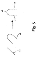
- Fig. 5 is a diagram showing characteristic extraction through
combination of basic shape characteristics;
- Fig. 6 is a diagram showing selection of a segment and a
reference point to avoid an aperture problem;
- Fig. 7 is a flowchart for selection of a reference point and
determination of a corresponding point;
- Fig. 8 is a diagram explaining an example of selected reference
points;
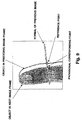
- Fig. 9 is a diagram explaining a provisional corresponding
point obtained;
- Fig. 10 is a diagram showing a transition of a reference point
to a corresponding point;
- Fig. 11 is a diagram illustrating a concept for calculation
of motion information;
- Fig. 12 is a diagram showing an applied example of the present
invention;
- Fig. 13 is a diagram showing a user authorization device;
- Fig. 14 is a diagram for inputting motion information to a
user authorization device, for comparison;
- Fig. 15 is a diagram showing a structure of a user
authorization system;
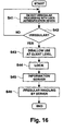
- Fig. 16 is a flowchart of processing for user authorization
system; and
- Fig. 17 is a flowchart of motion image processing in another
preferred embodiment.
-
BEST MODE FOR CARRYING OUT THE INVENTION
-
Preferred embodiments of the present invention will be
described with reference to the accompanying drawings.
-
Fig. 1 is a schematic diagram showing a structure of a motion
image processing device of the present invention. 1 is an image
capturing means having an image sensor for capturing an image of
an object, and specifically is a camera. 2 is A/D converter means
for converting image information in the form of an analogue signal
captured by the image capturing means 1 into image information in
the form of a digital signal. 3 is a frame memory for storing
digital image information, converted by the A/D converter means,
for every time series frame. 4 is a central processing unit (CPU)
for monitoring and controlling all of the processing devices,
storing algorithm constituting of process flows of a motion image
processing method of the present invention. 5 is a main memory
for use in signal processing by the CPU 4. 6 is a display means
for displaying an image processed by this processing device
-
Note that a digital camera having functions of an image
capturing means 1 and an A/D converter means 2 may be used as an
image capturing means 1, instead of an analogue camera mentioned
above, to achieve the object of the present invention.
-
Fig. 2 is a flowchart of a process procedure of a motion image
processing method relating to a preferred embodiment of the present
invention, which will be described below, while describing the
procedure.
-
As shown, this method includes image input (S20),
characteristic extraction (S21), reference point tracking (S22),
motion information calculation (S23), model modification and image
displaying (S24), each process being described in detail in the
following.
I. Characteristic Extraction to Determine Reference Point (S21)
-
In a preferred embodiment of the present invention, an object,
or a finger, is shot in advance using an image capturing means 1
at step S20 whereby contour shape information on the finger is
obtained.
-
Fig. 4 shows an example of detecting characteristic points
on a finger contour, based on edge information on a finger, detected
in the initial frame of time series images input. Respective marks
in the drawing represent characteristic points, including a
bending point (□) , a changing point (Δ), and a transition point
(×).
-
In the present invention, "a bending point" is a point, with
a quick change of an edge gradient direction based on edge
information. "A curving point" is a point on an object contour,
with inversion of a curvature sign and a moderate change of edge
gradient. "A transition point" is a point on an object contour,
with a change of a curvature from zero to another value, or vice
versa, and a moderate change of edge gradient.
-
At S21 in Fig. 2, a contour is divided into a straight line
segment and a concave or convex curve segment based on these
characteristic points.
-
Then, basic shape characteristics (segments), obtained by
dividing a contour, are combined according to a general
relationship.
-
Subsequently, a reference point for tracking (hereinafter
referred to as a tracking reference point) is selected from points
on a superior shape characteristic. In the example shown in Fig.
5, basic shape characteristics, namely a straight line segment (e1
in the drawing) and a curve segment (e2 in the drawing), are coupled
to each other at a transition point to thereby describe a superior
shape characteristic comprised of segments e1, e2, e3.
-
In this example, the segments e1 and e2, the segments e2 and
e3, and the segments e1 and e3 respectively have a relationship
(transition e1, e2), (transition e2, e3), and (parallel e1, e3).
Characteristics are extracted from an image, based on a description
of a superior shape characteristic, as described above.
-
Fig. 6 shows an example in which reference points are set on
a shape characteristic formed by combining segments. Here, when
points in the segment "a" are selected as reference points,
corresponding points thereof can be found properly in an image in
a different frame with respect to horizontal motion in the drawing.
However, with respect to vertical motion, proper corresponding
points cannot be obtained, except for a few points on the curving
part of the segment. This is referred to as an aperture problem
(a problem that a corresponding point corresponding to a tracking
reference point at time t cannot be uniquely determined at time
(t+1)), and must be avoided in motion image processing.
-
According to the present invention, this problem can be
avoided by selecting a plurality of segments, for example, segment
"a" and segment "b", each constituting a superior shape
characteristic of a finger, such that they form an angular
difference of about 90° between each other. A condition for
segment combination may be desirably determined as long as an
aperture problem can be avoided. Segments other than segment "b"
in Fig. 6 may be selected.
-
Further, points (a reference point) on a segment, for example
points in the segment "a" in Fig. 6, may be sampled with an equal
interval, for tracking.
II. Reference Point Tracking (S22)
-
At step S22, two or more (for example, at least four or more)
reference points () on the same plane in a 3D space are selected
from points selected at step S21 in the initial frame, and how the
selected reference points move to the respective corresponding
points in a different frame, in other words, in a predetermined
time, is detected.
-
It should be noted that the fact that two plane patterns
obtained by projecting a point on a plane in a 3D space onto two
different planes (e.g., an image projection plane, and so on) hold
an Affine convertible relationship, can be utilized.
-
Fig. 7 is a flowchart for selection of reference points and
determination of corresponding points thereof. As shown, this
method consists of a process for an initial image frame (S1) and
a process for subsequent image frames (S2).
-
At step S110, a contour of an object is extracted from the
initial image frame, and normal directions at respective points
on the contour are calculated based on a contour nearby (S110).
-
At step S120, reference points are selected from the points
on the contour in consideration of the normal directions (S120),
specifically, such that associated normal directions vary in two
or more directions, instead of deviating in one particular
direction, and that an angular difference of about 90 ° is formed
between each of the normal directions. In this embodiment, twenty
reference points are selected, and a reference point angle is set
at about 90° , which, however, is not a limiting example. Instead,
a reference point angle may be determined desirably in a range
between 45° and 135° , or even 80° and 100° .
-
Fig. 8 shows an example of reference points selected so as
to meet the above condition, in which ○ indicates a reference
point, and each segment at each reference point indicates a normal
direction at the associated reference point.
-
At step S2, reference points obtained at step S1 are tracked
in subsequent image frames.
-
In this embodiment, it is assumed that relationship between
a reference point and its corresponding point can be expressed by
means of Affine conversion. In actual fact, it is assumed that
motion of a finger is based on translation and rotation on a desired
plane, the motion can be expressed by means of Affine conversion.
Note that "a corresponding point" here refers to a point
corresponding to a reference point after an object, or a finger,
has moved.
-
Here, assuming that coordinates of a reference point and those
of a corresponding point are expressed as (X, Y) and (x, y),
respectively, they hold a relationship expressed by the following
polynomials (1), (2).
x= axX + bxY + e
y= cxX + dxY + f
wherein a, b, c, and d are coefficients indicative of rotation
components of the object motion, and e and f are coefficient
indicative of translation components thereof.
-
At step S210, a provisional corresponding point is determined
at a point where the normal of the associated reference point of
an object before motion (i.e., an object in a preceding image frame)
comes across the contour of the object moved (i.e., an object in
the next image frame) (S210). The crossing point between the
normal of the reference point and the contour can be determined
by examining luminous of pixels on the normal of the reference point
and finding a pixel having a significantly different luminous from
that of its adjacent pixel.
-
Fig. 9 is a diagram showing a reference point and a provisional
corresponding point corresponding to the reference point, in which
the contour represents the position of a finger in a preceding image
frame (i.e., a frame before the finger moved), ○ indicates a
reference point, and + indicates a provisional corresponding
point. A normal line of the reference point on the finger contour
in the preceding image frame is employed here.
-
At step S220, coefficients a, b, d, d, e, and f of the above
polynomials (1), (2) are obtained, based on coordinates of the
reference point and that of the provisional corresponding point.
However, the coefficients a, b, c, d, e, and f cannot be uniquely
determined because a provisional corresponding point is not a true
corresponding point. Therefore, in this embodiment,
approximations of coefficients a, b, c, d, e, and f are obtained
by means of least squares such that errors between the coordinates
obtained based on the reference point coordinates and using the
polynomials including coefficients a, b, c, d, e, and f obtained
as above, and the coordinates of a provisional coordinate point
is small, in other words, such that an average of the distances
for all twenty reference points is minimized (S220).
-
At step S230, positions to which the twenty reference points
will move are determined using coefficients a, b, c, d, e, and f,
obtained at step S220. Fig. 10 is a diagram showing transition
from a reference point in Fig. 9 to a provisional reference point.
According to the drawing, the reference point is supposed to have
moved to the first provisional reference point. Coordinates of
the first provisional reference points, however, do not coincide
with those of the corresponding point, though they are getting
closer, because of an error due to the fact that coefficients a,
b, c, d, e, and f obtained at step S220 of the polynomials are
approximations. This error can be reduced by obtaining a more
accurate approximation, using "a first provisional reference
point".
-
For this purpose, at step S240, the reference point is updated
(replaced) by the n-th provisional reference point, should a
distance between "the coordinates of the n-th provisional
reference point" and "those of the n-th provisional corresponding
point" be equal to or more than a predetermined threshold. With
updating of the provisional corresponding point and repetition of
the process at steps S220 and S230, the reference point sequentially
shifts to the first and then second provisional reference points.
Accordingly, approximations of coefficients a, b, c, d, e, and f
gradually converge until a final corresponding point is determined
(S220, S230, S240).
-
As a result of the processing at steps S220 and S230, it is
known that a reference point finally shifts to a corresponding point.
At step S250, that corresponding point is determined (S250).
-
At step S260, when a next image frame remains, the
corresponding point obtained at step S250 is used as a reference
point in the next image frame (S260).
III. Motion Information Calculation (S23)
-
At step S23 in Fig. 2, motion information of a plane pattern
is calculated based on a relationship between coordinates of a
reference point in an initial frame, which is tracked at step S22,
and those of its corresponding point in a frame at a different time,
and also on an assumption of limited motion (an assumption that
an object be within a view field and be reliably photographed even
for a frame at a different time) for a plane in a 3D space. Here,
by imparting a focal length of a lens of an image capturing system,
motion information can be obtained, including translation 3
freedom, rotation 3 freedom, a normal direction of the plane, and
a distance from the origin of a coordinate system to the foot of
perpendicular on the plane.
-
It should be noted that, because a translation vector is
obtained as a ratio relative to the distance, the distance must
be obtained in any method in order to calculate an accurate motion
amount, though any value may be used as the distance for relative
motion calculation.
-
An example of motion information calculation will be described
in the following.
-
In the case where a plane in air is observed, as shown in Fig.
11, motion of a place relative to a camera has the same effect as
the motion of a camera relative to a plane. Here, the latter will
be taken as an example. Given point P on a plane, P(x, y, z) can
be expressed as z=px+qy+r in a coordinate system having an origin
0 at the optical center of the camera before moving, wherein p,
q are plane gradient, and r is a distance along Z axis from 0 to
the plane. When the coordinates of a point in an image, obtained
by observing a point P on the plane, are (X, Y), and a focal distance
of the optical system is denoted as "f", X=fx/z, Y=fy/z are obtained.
Subsequently, suppose that the optical center of the image
capturing system is translated to point 0' by an amount T, and then
rotated around the center 0' by an amount R, and the same plane
is observed in the resultant image capturing system. In the
resultant coordinate system, point P on the plane can be expressed
as z'=p'x'+q'y'+r'. Likewise, assuming no change in the focal
distance of the optical system, point P (x, y, z) is expressed as
point P' (x', y', z') in the resultant coordinate system, and
X'=fx'/z', Y'=fy'/z' are obtained. Here, with T=(a, b, c)t, point
P and point P' hold the following relationship.

Based on the following (4) and (5), (6) is introduced.
wherein Tij is expressed as follows,
wherein k is a constant.
-
Based on the corresponding point in the image, nine unknown values
consisting of a rotation matrix, a translation vector, and a plane
parameter can be calculated through a least square method. Note
that a translation vector has freedom 8 as a relative value based
on a ratio relative to a distance to the plane, can be obtained.
IV. Model Manipulation Image Display (S24)
-
At step S24 in Fig. 2, a display object, such as a model or
a pointer, provided beforehand in a calculator, is subjected to
coordinate conversion, based on motion information calculated at
step S23, whereby the display object is modified according to the
motion of the object, supplied as an input image. Specifically,
a 3D model within the calculator may be moved or rotated for
modification or a cursor may be moved and so on according to the
motion of the finger.
-
Fig. 12 shows an example of application of the present
invention to on-line shopping using a solid model in a virtual
environment such as a virtual mall, or operation of a game character
in the field of amusements.
V. User Authentication (S34)
-
Fig. 3 is a flowchart of a process procedure of a system for
authenticating a user of a specific device, using the above
described motion information, to allow or prohibit use of the
specific device. A specific device may include a client device
equipped with a user authentication device (such as a calculator
and an access managing system) and a vehicle (such as airplanes,
ships, motorcycles, bicycles, automobiles, and so on) managed by
an individual or a corporation.
-
While processing at S20 to S23 in Fig. 3 is identical to
that at steps S20 to S23 in Fig. 2 and thus not described here in
detail, processing at steps S34 and thereafter will be described
with reference to Fig. 13 showing a device structure and Fig. 14
showing motion locus.
-
Prior to the process in Fig. 3, a user of a specific device
must register authentication information, such as motion
information, as an initial registration pattern, using an
authentication information input means 10 (image capturing means
1, A/D converter means 2, and frame memory 3 in Fig. 1). The
authentication information, such as motion information, is stored
in the authentication information storage means 11.
-
To use a specific device, at step S34, motion information of
an object (e.g., a finger), input via the authentication
information input means 10 and calculated at S23, is compared via
the authentication information comparison means 12 with an initial
registration pattern 100 (initial motion information), registered
in the authentication information storage means 11, and it is
determined that the person is an authorized user when motion
information 102 identical to the initial registration pattern 100
(initial motion information) was input. On the contrary, it is
determined that the person is not an authorized user when motion
information 102 different from the initial registration pattern
100 (initial motion information) was input.
-
When it is determined at step S35 that the person who input
the motion information is a registered, authorized user, the use
allowing control means 13 sends a signal to the specific device
to allow the use thereof by that person. Whereas, when illegal
use by a person other than a registered, authorized person is
detected, the use allowing control means 13 sends a signal to the
specified device at step S37 to prohibit the use thereof by that
person.
-
Through the above processing, motion information is usable
as a type of ID information, as a result of which, for example,
a user is released from the burden of possessing his automobile
key all the time, as he conventionally required.
-
Fig. 15 is a diagram showing a preferred embodiment in which
predetermined data is exchanged between a security managing server
and a specific device described above via a network (Internet,
portable phones, radio communication).
-
In the drawing, as described above with reference to Fig. 13,
a user of a specific device registers beforehand an initial
registration pattern (initial motion information) to the
authentication information storage means 11 via the authentication
information input means 10 (the image capturing means 1, A/D
converter means 2, and frame memory 3 in Fig. 1), and thereafter
inputs motion information using his finger and so on when wishing
to use the specific device, and, the use allowing control means
13 sends a use allowing/prohibiting signal to the specific device
based on the result. Here, in addition, there is provided a system
capable of obtaining position information of a specific device
(hereinafter an automobile will be referred to as an example) should
the device be stolen, and taken away. Operation of the system will
be described with reference to Figs. 15 and 16.
-
At step S41 in Fig. 16, an automobile user inputs motion
information via the authentication information input means 10 when
wishing to use the automobile. The authentication information
comparison means 12 compares the input motion information and the
initial registration pattern (initial motion information)
registered in the authentication information storage means 11 to
see whether or not they are identical. When it is determined at
step S42 that the input information differs from the initial
registration pattern (initial motion information) stored in the
authentication information storage means 11, the use allowing
control means 13 sends a use prohibiting signal to the automobile
at step S43, and a signal to lock the door or to prohibit engine
start at step S44.
-
At step S45, the central control means 16 of the user
authentication device sends an irregular signal notifying of
dispatch of a use prohibiting signal and an ID number of the
associated automobile via the communication means 15, a network,
and the server communication means 22. Also, the central control
means 16 sends a command to a transmitter/receiver means 14 to
direct output of transmission radio waves.
-
At step 546, receiving the irregular and ID signals, the server
applies irregular processing. Specifically, the
transmitter/receiver means 21 on the server side receives the radio
waves from the transmitter/receiver means 14 via a satellite means
to detect location information of the automobile associated with
that user authentication device.
-
With the above, an automobile can be located even if an
automobile with locked doors is stolen, and thus can be easily
searched for.
-
It should be noted that, when a specific device is not an
automobile, different from the above, the door locking process at
step S44 may be substituted accordingly. For example, for
calculators, log-in may not be allowed. For an access managing
device and so on, doors may be closed. Note that the present
invention is not limited to these examples and other processing
for prohibiting the use of a specific device may be applicable.
-
Further, the present invention can be applied to a client
device equipped with a user authentication device, such as
airplanes, ships, motorcycles, bicycles, rent safes, which are
managed by an individual or a corporation.
-
For a specific device in the form of a calculator, a server
may supply a signal for releasing a log-in state via a network even
though log-in has failed once.
-
As is obvious from the above, the present invention offers
advantages of input of a 3D coordinate conversion parameter
obtained from a monochrome image captured via one camera, and of
modification of a model according to the input parameter.
-
Specifically, a special coordinate input device or equipment
is unnecessary to input motion information because a tracking
reference point is automatically determined through detection of
an index finger and a thumb in an input image.
-
Further, illegal use of a specific device can be prevented
through detection of an irregular state upon detection of a
different pattern through comparison between motion information
input when a user desires to use the specific device, and a
pre-registered initial registration pattern (initial motion
information).
-
Instead of initial motion information used as initial
registration pattern in this embodiment, other known initial
registration patterns, including the iris, finger prints, and
audio number information, may be used for authentication of a
specific device.
-
Fig. 17 is a flowchart showing a process procedure for a motion
image processing method in another preferred embodiment of the
present invention, which corresponds to modification of the
process in Fig 7 in the above embodiment.
-
As shown, the method of this embodiment consists of processing
for an initial image frame (S1) and that for subsequent image frames
(S2). Each processing will be described below.
I. Processing using Initial Image Frame (S1)
-
In this preferred embodiment, at step S110, an object, or a
finger, is shot beforehand using a image capturing means 1, whereby
contour information of the finger is obtained at step S120 (S120).
-
At step S130, whether to apply characteristic extraction at
step S140 or to skip step S140 is determined in selecting a reference
point from points on the contour for object tracking (S130). In
the following, characteristic extraction processing at step S140
to be applied when it is determined to be necessary at step S130
will be described.
Ia. Normal Directions at Points on Contour to be Considered
-
At step S140, normal directions are calculated as for the
respective points extracted at step S120 on the object contour,
using information on a contour nearby (S140). At step S150,
reference points are selected from points on the contour in
consideration of the normal directions (S150), specifically, such
that normal directions thereof may vary in two or more directions,
rather than deviating in one particular direction, and that an
angular difference about 90 ° may be formed between each of the
normal directions. In this embodiment, twenty reference points
are selected, and a reference point angle is set at about 90°,
which, however, is not a limiting example. Instead, a reference
point angle may be determined desirably in a range between 45°
and 135° , or even 80° and 100°
Ib. Basic Shape Characteristic of Contour to be Considered
-
At step S140, characteristic points are detected from among
respective points extracted at step S120 on an object contour, and
divided into a straight line segment and a curve segment. Further,
the contour shape is extracted as a shape characteristic, based
on a description expressed through combination of these segments
(S140). Further, at step S150, a reference point is determined
for tracking the object, based on the extracted shape
characteristic (S150).
II. Processing for Subsequent Image Frames (S2)
-
At step S2, the reference point obtained at step S1 is tracked
in subsequent image frames. The processing here includes
reference point tracking (S210 to S270), motion information
calculation (S280), and model modification and image display
(S290).
IIa. Reference Point Tracking (S210 to S270)
-
In this embodiment, it is assumed that a relationship between
a reference point and its corresponding point can be expressed by
means of Affine conversion. At steps S210 to S270, a plurality
of (for example, at least four) reference points on the same plane
in a 3D space are selected from those selected at step S150 in the
initial frame, and how the selected reference points move to the
respective corresponding points in a different frame, in other
words, in a predetermined time, is detected.
-
It should be noted that the fact that two plane patterns
obtained by projecting a point on a plane in a 3D space into two
different planes (e.g., an image projection plane, and so on) hold
a relationship adaptable to Affine conversion, can be utilized.
In actual fact, when motion of a finger is limited to translation
and rotation on a desired plane in a 3D space, with respect to a
display object of an image obtained by photographing an object,
a relationship between corresponding points in images in different
frames can be expressed by means of Affine conversion.
Specifically, reference points may be tracked in the same manner
as described in the above embodiment.
-
Finally, at step S300, when next image frame remains, the
corresponding point obtained at step S270 is used as a reference
point in the next image frame (S310). Accordingly, motion of an
object can be tracked based on a coordinate conversion parameter,
as obtained above, from "a reference point" to "a corresponding
point".
IIb. Motion Information Calculation (S280)
-
At step S280 in Fig. 17, motion information of a plane pattern
is calculated based on a relationship between coordinates of a
reference point in an initial frame and those of its corresponding
point in a frame at a different time, tracked at step S270, and
also on an assumption of limited motion (an assumption such that
an object be within a view field and be reliably photographed even
for a frame at a different time) for a plane in a 3D space. Here,
by imparting a focal length of a lens of an image capturing system,
motion information can be obtained, including translation 3
freedom, rotation 3 freedom, a normal direction of the plane, and
a distance from the origin of a coordinate system to the foot of
perpendicular on the plane.
-
It should be noted that, because a translation vector is
obtained as a ratio relative to the distance, the distance must
be obtained in any method in order to calculate an accurate motion
amount, though any value may be used as the distance for relative
motion calculation.
IIc. Model Modification and Image Display (S290)
-
At step S290 in Fig. 17, a display object, such as a model
or a pointer, provided beforehand in a calculator, is subjected
to coordinate conversion, based on motion information calculated
at step S280, whereby the display object is modified according to
the motion of the object, supplied as an input image. Specifically,
a 3D model within the calculator may be moved or rotated for
modification or a cursor may be moved and so on according to the
motion of a finger.
-
Also in this embodiment, on-line shopping using a solid model
in a virtual environment such as a virtual mall, or operation of
a game character in the field of amusements, can be performed.


 wherein Tij is expressed as follows,
 wherein k is a constant.