EP1138397A2 - Opener for opening a tubular bag comprising a pasty material - Google Patents
Opener for opening a tubular bag comprising a pasty material Download PDFInfo
- Publication number
- EP1138397A2 EP1138397A2 EP01108464A EP01108464A EP1138397A2 EP 1138397 A2 EP1138397 A2 EP 1138397A2 EP 01108464 A EP01108464 A EP 01108464A EP 01108464 A EP01108464 A EP 01108464A EP 1138397 A2 EP1138397 A2 EP 1138397A2
- Authority
- EP
- European Patent Office
- Prior art keywords
- piercing
- actuating element
- piercing tube
- tubular bag
- mixer
- Prior art date
- Legal status (The legal status is an assumption and is not a legal conclusion. Google has not performed a legal analysis and makes no representation as to the accuracy of the status listed.)
- Granted
Links
Images


Classifications
-
- B—PERFORMING OPERATIONS; TRANSPORTING
- B05—SPRAYING OR ATOMISING IN GENERAL; APPLYING FLUENT MATERIALS TO SURFACES, IN GENERAL
- B05C—APPARATUS FOR APPLYING FLUENT MATERIALS TO SURFACES, IN GENERAL
- B05C17/00—Hand tools or apparatus using hand held tools, for applying liquids or other fluent materials to, for spreading applied liquids or other fluent materials on, or for partially removing applied liquids or other fluent materials from, surfaces
- B05C17/005—Hand tools or apparatus using hand held tools, for applying liquids or other fluent materials to, for spreading applied liquids or other fluent materials on, or for partially removing applied liquids or other fluent materials from, surfaces for discharging material from a reservoir or container located in or on the hand tool through an outlet orifice by pressure without using surface contacting members like pads or brushes
- B05C17/00553—Hand tools or apparatus using hand held tools, for applying liquids or other fluent materials to, for spreading applied liquids or other fluent materials on, or for partially removing applied liquids or other fluent materials from, surfaces for discharging material from a reservoir or container located in or on the hand tool through an outlet orifice by pressure without using surface contacting members like pads or brushes with means allowing the stock of material to consist of at least two different components
-
- A—HUMAN NECESSITIES
- A61—MEDICAL OR VETERINARY SCIENCE; HYGIENE
- A61C—DENTISTRY; APPARATUS OR METHODS FOR ORAL OR DENTAL HYGIENE
- A61C5/00—Filling or capping teeth
- A61C5/60—Devices specially adapted for pressing or mixing capping or filling materials, e.g. amalgam presses
- A61C5/62—Applicators, e.g. syringes or guns
- A61C5/64—Applicators, e.g. syringes or guns for multi-component compositions
-
- A—HUMAN NECESSITIES
- A61—MEDICAL OR VETERINARY SCIENCE; HYGIENE
- A61C—DENTISTRY; APPARATUS OR METHODS FOR ORAL OR DENTAL HYGIENE
- A61C9/00—Impression cups, i.e. impression trays; Impression methods
- A61C9/0026—Syringes or guns for injecting impression material; Mixing impression material for immediate use
-
- B—PERFORMING OPERATIONS; TRANSPORTING
- B01—PHYSICAL OR CHEMICAL PROCESSES OR APPARATUS IN GENERAL
- B01F—MIXING, e.g. DISSOLVING, EMULSIFYING OR DISPERSING
- B01F27/00—Mixers with rotary stirring devices in fixed receptacles; Kneaders
- B01F27/05—Stirrers
-
- B—PERFORMING OPERATIONS; TRANSPORTING
- B01—PHYSICAL OR CHEMICAL PROCESSES OR APPARATUS IN GENERAL
- B01F—MIXING, e.g. DISSOLVING, EMULSIFYING OR DISPERSING
- B01F27/00—Mixers with rotary stirring devices in fixed receptacles; Kneaders
- B01F27/05—Stirrers
- B01F27/07—Stirrers characterised by their mounting on the shaft
- B01F27/072—Stirrers characterised by their mounting on the shaft characterised by the disposition of the stirrers with respect to the rotating axis
- B01F27/0724—Stirrers characterised by their mounting on the shaft characterised by the disposition of the stirrers with respect to the rotating axis directly mounted on the rotating axis
-
- B—PERFORMING OPERATIONS; TRANSPORTING
- B05—SPRAYING OR ATOMISING IN GENERAL; APPLYING FLUENT MATERIALS TO SURFACES, IN GENERAL
- B05C—APPARATUS FOR APPLYING FLUENT MATERIALS TO SURFACES, IN GENERAL
- B05C17/00—Hand tools or apparatus using hand held tools, for applying liquids or other fluent materials to, for spreading applied liquids or other fluent materials on, or for partially removing applied liquids or other fluent materials from, surfaces
- B05C17/005—Hand tools or apparatus using hand held tools, for applying liquids or other fluent materials to, for spreading applied liquids or other fluent materials on, or for partially removing applied liquids or other fluent materials from, surfaces for discharging material from a reservoir or container located in or on the hand tool through an outlet orifice by pressure without using surface contacting members like pads or brushes
- B05C17/00503—Details of the outlet element
- B05C17/00506—Means for connecting the outlet element to, or for disconnecting it from, the hand tool or its container
-
- B—PERFORMING OPERATIONS; TRANSPORTING
- B05—SPRAYING OR ATOMISING IN GENERAL; APPLYING FLUENT MATERIALS TO SURFACES, IN GENERAL
- B05C—APPARATUS FOR APPLYING FLUENT MATERIALS TO SURFACES, IN GENERAL
- B05C17/00—Hand tools or apparatus using hand held tools, for applying liquids or other fluent materials to, for spreading applied liquids or other fluent materials on, or for partially removing applied liquids or other fluent materials from, surfaces
- B05C17/005—Hand tools or apparatus using hand held tools, for applying liquids or other fluent materials to, for spreading applied liquids or other fluent materials on, or for partially removing applied liquids or other fluent materials from, surfaces for discharging material from a reservoir or container located in or on the hand tool through an outlet orifice by pressure without using surface contacting members like pads or brushes
- B05C17/00503—Details of the outlet element
- B05C17/00516—Shape or geometry of the outlet orifice or the outlet element
-
- B—PERFORMING OPERATIONS; TRANSPORTING
- B05—SPRAYING OR ATOMISING IN GENERAL; APPLYING FLUENT MATERIALS TO SURFACES, IN GENERAL
- B05C—APPARATUS FOR APPLYING FLUENT MATERIALS TO SURFACES, IN GENERAL
- B05C17/00—Hand tools or apparatus using hand held tools, for applying liquids or other fluent materials to, for spreading applied liquids or other fluent materials on, or for partially removing applied liquids or other fluent materials from, surfaces
- B05C17/005—Hand tools or apparatus using hand held tools, for applying liquids or other fluent materials to, for spreading applied liquids or other fluent materials on, or for partially removing applied liquids or other fluent materials from, surfaces for discharging material from a reservoir or container located in or on the hand tool through an outlet orifice by pressure without using surface contacting members like pads or brushes
- B05C17/00583—Hand tools or apparatus using hand held tools, for applying liquids or other fluent materials to, for spreading applied liquids or other fluent materials on, or for partially removing applied liquids or other fluent materials from, surfaces for discharging material from a reservoir or container located in or on the hand tool through an outlet orifice by pressure without using surface contacting members like pads or brushes the container for the material to be dispensed being deformable
-
- B—PERFORMING OPERATIONS; TRANSPORTING
- B05—SPRAYING OR ATOMISING IN GENERAL; APPLYING FLUENT MATERIALS TO SURFACES, IN GENERAL
- B05C—APPARATUS FOR APPLYING FLUENT MATERIALS TO SURFACES, IN GENERAL
- B05C17/00—Hand tools or apparatus using hand held tools, for applying liquids or other fluent materials to, for spreading applied liquids or other fluent materials on, or for partially removing applied liquids or other fluent materials from, surfaces
- B05C17/005—Hand tools or apparatus using hand held tools, for applying liquids or other fluent materials to, for spreading applied liquids or other fluent materials on, or for partially removing applied liquids or other fluent materials from, surfaces for discharging material from a reservoir or container located in or on the hand tool through an outlet orifice by pressure without using surface contacting members like pads or brushes
- B05C17/00586—Means, generally located near the nozzle, for piercing or perforating the front part of a cartridge
-
- B—PERFORMING OPERATIONS; TRANSPORTING
- B05—SPRAYING OR ATOMISING IN GENERAL; APPLYING FLUENT MATERIALS TO SURFACES, IN GENERAL
- B05C—APPARATUS FOR APPLYING FLUENT MATERIALS TO SURFACES, IN GENERAL
- B05C17/00—Hand tools or apparatus using hand held tools, for applying liquids or other fluent materials to, for spreading applied liquids or other fluent materials on, or for partially removing applied liquids or other fluent materials from, surfaces
- B05C17/005—Hand tools or apparatus using hand held tools, for applying liquids or other fluent materials to, for spreading applied liquids or other fluent materials on, or for partially removing applied liquids or other fluent materials from, surfaces for discharging material from a reservoir or container located in or on the hand tool through an outlet orifice by pressure without using surface contacting members like pads or brushes
- B05C17/00596—The liquid or other fluent material being supplied from a rigid removable cartridge having no active dispensing means, i.e. the cartridge requiring cooperation with means of the handtool to expel the material
-
- B—PERFORMING OPERATIONS; TRANSPORTING
- B01—PHYSICAL OR CHEMICAL PROCESSES OR APPARATUS IN GENERAL
- B01F—MIXING, e.g. DISSOLVING, EMULSIFYING OR DISPERSING
- B01F2101/00—Mixing characterised by the nature of the mixed materials or by the application field
- B01F2101/2305—Mixers of the two-component package type, i.e. where at least two components are separately stored, and are mixed in the moment of application
-
- B—PERFORMING OPERATIONS; TRANSPORTING
- B01—PHYSICAL OR CHEMICAL PROCESSES OR APPARATUS IN GENERAL
- B01F—MIXING, e.g. DISSOLVING, EMULSIFYING OR DISPERSING
- B01F33/00—Other mixers; Mixing plants; Combinations of mixers
- B01F33/50—Movable or transportable mixing devices or plants
- B01F33/501—Movable mixing devices, i.e. readily shifted or displaced from one place to another, e.g. portable during use
- B01F33/5011—Movable mixing devices, i.e. readily shifted or displaced from one place to another, e.g. portable during use portable during use, e.g. hand-held
Definitions
- the invention relates to a device for discharging a pasty two-component mixture, which is e.g. to be a mixture of one Dental impression material and one that initiates or accelerates curing Catalyst acts.
- Dispensing devices are used to apply multicomponent materials as a mixture known that a storage container with at least two chambers each for one of the pasty components of the mixture.
- everyone Chamber is assigned an outlet port through which the pasty component emerges when pressurized.
- a mixer unit which has a mixer housing, is placed on the outlet nozzle with a substantially tubular section and a coupling end for connection to the storage container.
- a mixer element In the tubular Section of the mixer housing is a mixer element that leads to a Swirling and mixing of the supplied through separate channels Components. These channels are in the coupling end of the Mixer housing formed and extend from two inlet ports of the Coupling end to the mixer element.
- Such a device is for example in EP-A-0 730 913.
- the mixer housing at its coupling end by means of a holding sleeve releasably locked to the storage container.
- the holding sleeve is rotatable on the Mixer housing mounted and has a bayonet lock trained radially outward anchoring projections on Rotation under corresponding overlap projections of the storage container are movable.
- the invention also relates to a device for opening a tubular bag, in which there is a pasty mass. Furthermore, with this device the pasty mass can also be led out of the tubular bag.
- the pasty masses are in rigid containers or cartridges with movable Floor walls offered by means of manual or motorized advancing stamp elements are advanced to apply pressure to the to apply pasty masses, which causes them from the cartridges or containers be carried out.
- the to offer pasty masses in tubular bags These need to be the Apply pasty mass, preferably opened at its front ends become. This happens, for example, with fixed piercing pins or the like Cutting elements arranged on the end wall of a receiving cap are, which surrounds the front end of a tubular bag and has a discharge nozzle.
- the invention has for its object a device for discharge of a pasty two-component mixture with a mixer unit create that has a reduced number of individual parts.
- the Holding sleeve holding mixer unit not on mixer housing but on Storage container.
- the holding sleeve is on this storage container about its longitudinal axis rotatably mounted.
- the holding sleeve surrounds the two outlet ports of the Storage container and points to its facing away from the storage container front end of a recess in a first rotational position of the Holding sleeve (mounting rotational position) the plug on the mixer housing the outlet port of the reservoir allows during the recess delimiting edge of the holding sleeve in a second rotational position (Locking rotational position) over partial areas of the coupling end, for example over radially projecting flange sections of the coupling end of the Mixer housing, is moved and thus the mixer housing on the storage container locked.
- the holding sleeve is therefore no longer part of the Mixer unit, so remains for the entire duration during which the discharge device used to apply the two-component mixture will receive.
- the coupling end has two diametrically opposite and radially protruding projections, while the Holding sleeve one of the cross-sectional shape of the coupling end at the level thereof Has protrusions of the same shape.
- the coupling end of the mixer housing in the area of the radial projections essentially oval.
- the recess is in its receiving rotational position the holding sleeve relative to the arrangement of the outlet nozzle of the storage container aligned as the inlet connection of the mixer housing relative to the outer projections. This allows the coupling end of the mixer housing move through the front recess of the holding sleeve, until the inlet connection of the mixer housing from the outlet connection of the Storage container or vice versa.
- the recess edge of the holding sleeve is located above the outer projections at the coupling end of the mixer housing, so that by twisting areas of the recess edge in the locking rotational position overlap the outer projections.
- the holding sleeve is expedient in both of these rotational positions against unintentional further rotation or back rotation, which is conveniently by a corresponding locking takes place.
- the holding sleeve is it is also useful if this is only between their shooting rotational position and rotates their locking rotational position.
- Another aspect of the invention relates to a device for opening a to create a pasty mass containing tubular bag with which the tubular bag can be opened without the tubular bag or the pasty mass must be exposed to external pressure.
- the piercing tube manually from a retreat position in which the piercing tube does not protrude above the system level, can be moved into a feed position, in which the piercing tube protrudes beyond the investment level.
- the device according to the invention is provided with a piercing tube, which is guided axially displaceably in the discharge nozzle of a receiving cap is.
- a discharge nozzle Through this discharge nozzle, when the tubular bag is open, the pasty mass to be applied directly or, in the case of a two-component material, mixed with another component of the pasty mass to become.
- the discharge nozzle is on the front wall of the receiving cap protruding from this, with the end wall in to Discharge nozzle opposite direction protrudes a peripheral edge.
- the receiving cap surrounds one of the two end faces Ends of the tubular bag, the end face of which on the end wall of the receiving cap rests in a contact surface formed by this.
- the piercing tube the device according to the invention is manually from a retracted position slidable into a feed position. This shift can either done directly manually by tapping the vial by hand is moved within the nozzle, or indirectly by a Actuator is moved manually, which in turn over a contact surface is in contact with the piercing tube and thus the Also moves the piercing tube.
- the piercing tube can be used in both cases from the retreat position, in which it does not have that formed by the bulkhead Projecting plane of the receiving cap protrudes into the feed position, in which it survives over the plant level and thus at the Receiving cap of the tubular film bag in the end face immersed and opened the tubular bag.
- the piercing tube can be inserted into the socket at the factory and is therefore in it Treatment position.
- the piercing tube is inserted into the nozzle by the user.
- it is useful if the piercing tube in its retracted position by a Latching or the like against unintentional movement from the retreat position is secured out. This is beneficial for the user for whom thus the retraction position is tactile as a defined position of the piercing tube represents.
- the advantage of the opening device according to the invention is that the process of opening the tubular bag from the process of discharge the pasty mass is separated from the tubular bag. With that stands the tubular bag when opening no longer under increased pressure, so that accidentally no pasty mass from the Tubular bag can leak. This simplifies the handling of the Tubular bag.
- the device according to the invention can be used both for receiving caps a single tubular bag as well as with combined receiving caps for use several, for example two tubular bags.
- the receiving cap has several discharge nozzles, each with are provided with a piercing tube.
- These piercing tubes can be used with each other be connected to them together in the respective tubular bag to drive in. But it is also quite possible that the piercing tube are not interconnected, so each tubular bag separately can be "pierced”.
- the piercing tube is in its retracted position over the discharge end facing away from the end wall of the receiving cap survives. Then the axial displacement of the piercing tube can be done by simply moving it into the nozzle. As soon as the piercing tube has been completely moved into the nozzle reached the feed position and the piercing tube into the tubular bag driven into it.
- the piercing tube is expediently both in its feed position against unintentional backward movements towards the retreat position as well as in its retreat position against unwanted movements in the Feed position secured. As already mentioned above, this can be done by the piercing tube is locked in or on the nozzle.
- a An alternative to this is that in its retreat position from the The nozzle protrudes through a detachable piercing tube Cover cap is protected, which can be put over the nozzle and on Is fixable. This cover cap is used for transport security and is removed before moving the piercing tube, for example unscrewed or the like to expose the piercing tube.
- An alternative to the cover cap is a spacer that between the the nozzle protruding end of the piercing tube and the user the nozzle is arranged.
- This spacer is special formed as a spring clip that surrounds the piercing tube. This spring clip can be withdrawn from the side of the piercing tube so that it is then attached is axially displaceable. The spacer is supported between an outer protrusion on the piercing tube and the discharge of the Neck.
- the actuating element is advantageously in the manner of one on the Socket arranged sleeve element is formed, which extends axially over the Can move the nozzle.
- This sleeve element is in two axial positions, which correspond to the withdrawal position and the feed position of the piercing tube, on the socket or on the receiving cap against unintended Lockable axial movements.
- the sleeve element is advantageously as Screw element formed, which has an internal thread section, the can be brought into engagement with an external thread section on the connecting piece.
- the sleeve element can be moved axially, to drive the puncture tube into the film tube.
- Either both the sleeve element and the socket have their threaded sections on both sides Areas that are free of threads. So long the two thread sections are not in threaded engagement with each other, leads to a twist of the sleeve element does not lead to an axial displacement. Also prevent the two thread sections not in threaded engagement with one another a linear axial displacement of the sleeve element. So this is it before and after the thread engagement of the two thread sections against unwanted axial movements secured.
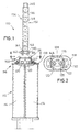
- Fig. 1 shows a partially sectioned side view of an application device 110 for pasty two-component mixtures.
- Applicator 110 comprises a rigid storage container 112 with two substantially cylindrical ones Chambers 114 for receiving a pasty component.
- the storage container 112 At the the front end 116, the storage container 112 has an end wall 118, of the two outlet ports corresponding to one of the chambers 114 Stand out 120.
- the holding sleeve 122 instructs their protruding beyond the outlet nozzle 120 and facing away from the end wall 118 front end 124 a recess 126 in the form of one of a Cut-out edge 128 opening enclosed on all sides.
- the coupling end 130 of a mixer unit 132 is inserted into the holding sleeve 122 introducing a mixer housing 134 with a tubular portion 136 having.
- a mixer element is located in the tubular section 136 138.
- the tubular portion 136 has an outlet end 140, while the coupling end 130 has two inlet ports 142 with them from there has separate channels 144 extending to the mixer element 138.
- the Opening 126 has an essentially oval shape.
- the coupling end 130 of the mixer housing 134 is formed in the opening shape.
- the mixer unit 132 can thus be adjusted when the holding sleeve 122 is aligned 2 with the coupling end 130 move through the opening 126, until the inlet port 142 is received by the outlet port 120 are.
- the opening edge 128 overlaps the Holding sleeve 122, the two diametrically opposite and radially protruding Shoulder surfaces 146 in the transition area between the tubular Section 134 and the flange-like coupling end 130 of the Mixer unit 132.
- This locking rotational position is shown in FIGS. 3 and 4 shown. In this rotational position of the holding sleeve 122, it therefore overlaps part of its opening edge 128 the coupling end 130 of the mixer unit 132 and thus keeps the mixer unit 132 in the storage container 112 connected operating state.
- Figs. 2 and 4 is also indicated that the holding sleeve 122 in its two in this embodiment, rotary end positions offset by 90 ° from one another is secured with respect to a further rotation. This will realized by a radially projecting stop element 148 on the holding sleeve 122, each against a counter element arranged on the front wall 118 150 stops.
- the two counter elements 150 are diametrically opposite arranged and overlap an annular flange 152 of the holding sleeve 122, in addition to their function as a rotation limit, they also provide the rotatable one Storage of the holding sleeve 122 on the storage container 112.
- the interface between the mixer unit 132 and the storage container 112 to code, so that the mixer unit 132 is only in one certain orientation of the mixer unit 132 and the holding sleeve 122 leaves.
- This coding can also be done by additional interrelated Projection and recess elements on the mixer unit 132 and the reservoir 112 can be realized.
- the mixer interface is above in its application with a rigid one Storage container described with a static mixer, but can also be used use so-called dynamic mixers, which are driven by a rotating Mixer shaft. Furthermore, the coupling of the mixer can also in a pressure vessel for pasty contained in tubular bags Material can be realized. Such systems require special opening mechanisms, with which the tubular bags can be opened. Below such a tubular bag opening system is described.
- Figs. 5 to 7 is a first embodiment of a device 10 shown for opening two tubular bags.
- the device 10 has one Receiving cap 12 on, with an end wall 14 and one of these projecting edge 16 is provided.
- a nozzle 22 protrudes.
- the end wall 14 has one between the two openings 18, 20 Partition 30, which protrudes from the end wall 14 in the direction of the edge 16. This creates two receiving spaces for two tubular bags 32,34, each containing a pasty mass 36,38.
- the front Ends 40, 42 of the two tubular bags 32, 34 are from the receiving cap 12 or the edge 16 and the intermediate wall 30, the End faces 44, 46 of the tubular bags 32, 34 along a contact plane 47 of the end wall 14 of the receiving cap.
- the tubular bag 32, 34 can be firmly connected to the receiving cap 12, for example done by gluing.
- each channel 24, 26 there is a piercing tube 48, 50, which is a tapered one and thus has a pointed piercing end 52, 54.
- the two Piercing tubes 48, 50 are arranged axially displaceably in the channels 24, 26 and are in their retracted position according to FIG. 5 above the discharge end 28 of the nozzle 22 over.
- the ends of 56.58 are the two piercing tubes 48.50 one below the other connected, which is shown at 60.
- the task of the piercing tube 48.50 is on the one hand, by penetrating the end faces 44, 46 the tubular bags 32.34 to open, and the other with open tubular bags 32.34 pasty masses to pass 36.38 for the purpose of spreading the same.
- the Screw cap 62 which acts as an actuating element serves to axially move the piercing tube 48.50.
- the Screw cap 62 is substantially cylindrical and has the receiving cap on it 12 facing one end 64 is an internally threaded section 66 on.
- At the other end 68 is the screw cap 62 with an inner shoulder 70 provided on a circumferential radial flange of the two piercing tubes 48.50 is present. Between the inner shoulder 70 and the internally threaded portion 66, the screw cap 62 is smooth on the inside trained without protrusion.
- the connector 22 has a Male thread portion 74 which is with the female thread portion 66 of Screw cap 62 can be brought into threaded engagement.
- the External thread section 74 of the connector 22 has this smooth, protrusion-free Areas whose axial extent is equal to or slightly larger than is the axial extent of the internal thread section 66.
- the nozzle 22 facing away from the front end 28 is the nozzle 22 with a provided external locking projection 76.
- the screw cap 62 is factory-fitted over the locking projection 76 pushed the nozzle 22 until the internal thread portion 66 between the locking projection 76 and the external thread section 74 of the Socket 22 is located (see Fig. 5). They are in this situation Piercing mandrels 48, 50 which are inserted into the channels 24, 26 in front of the screw cap 62 in their retracted position with their piercing tips 52,54 do not protrude beyond plant level 47. Remain in this retreat position the piercing pins 48, 50 even if the screw cap 62 in A force is exerted in the axial direction, since the internal thread and external thread sections 66, 74 prevent movement of the cap 62.
- a piercing mandrel 48, 50 can be a dynamic one or static mixer 77, in which the through the Piercing spikes 48.50 pasty material 36.38 mixed together becomes.
- the mixer 77 is held on the screw cap 62, in exactly the same way, like the mixer unit 132 on the storage container by means of the holding sleeve 122 112 according to FIGS. 1 to 4 is held.
- the screw cap 62 therefore has a double function, by starting from FIG. 6 first of all the advance movement of the Piercing pins 48.50 into the tubular bags 32.34 (FIGS.
- the locking of the screw cap 62 in its respective rotational position and the locking position and the limitation of the twist, as in Connection with the holding sleeve 122 according to the embodiment of FIG Fig. 1 to 4 can be described by locking the screw cap 62 realize with the receiving cap 12. Because the axial distance of the screw cap 62 from the receiving cap 12 when screwing onto the socket 22 in order to advance the piercing pins 48.50 to the conditions in the position 7 is different, the latching and movement limitation be designed in such a way that latching projections required for this and depressions and attacks only work together when 7, the threaded portions 66, 74 are disengaged.
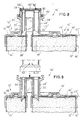
- Fig. 8 and 9 show an alternative embodiment of the opening device 10 '.
- the individual parts of this device 10 'of those according to the Fig. 5 to 6 correspond or have the same function with these, they are with the same reference numerals, but simply deleted.
- the device 10 ' is a separate receiving cap for each tubular bag 32', 34 ' 12 'with an end wall 14' and a circumferential projecting edge 16 ' intended.
- Each receiving cap 12 ' has a nozzle 22' with one pulling channel 24 'or 26'.
- two piercing tubes 48 ', 50' in the retracted position 8 protrude beyond the ends 28 'of the nozzle 22'.
- the Piercing tubes 48 ', 50' are on their receiving caps 12 'facing away Ends 56 ', 58' joined together at 60 '.
- the device 10 ' has a protective cap 78 on, which is detachably connected to the nozzle 22 ', which in Fig. 8 by corresponding Overlap and underlap projections 80.82 on the spigot 22 ' or the cap 78 is realized. By turning the cap 78, these can be Disengage protrusions 80, 82 and thereby cap 78 lose weight.
- Figs. 10 and 11 is a third embodiment of an apparatus 10 ", which is an alternative to the device 10 '.
- the difference from the device 10 ' is the securing of the piercing tubes 48 “, 50” against unintentional movements from the retreat position in the feed position.
- a spacer 84 designed as a spring clip is used, which from the Ends 28 "of nozzle 22" protruding piercing tubes 48 “, 50” from surrounds the outside and thus between the circumferential outer flange 72 " Piercing tube 48 “, 50” and the end 28 "of the nozzle 22" is arranged (see Fig. 11).
- the clip 84 is designed as a two-leg bracket both brackets 86 on their opposite longitudinal edges 88 on the one hand on the flange 72 "and on the other hand at the ends 28" of the nozzle 22 ".
Abstract
Description
Die Erfindung betrifft eine Vorrichtung zum Austragen eines pastösen Zweikomponenten-Gemisches, bei dem es sich z.B. um ein Gemisch aus einer Dental-Abformmasse und einem die Aushärtung initiierenden bzw. beschleunigenden Katalysator handelt.The invention relates to a device for discharging a pasty two-component mixture, which is e.g. to be a mixture of one Dental impression material and one that initiates or accelerates curing Catalyst acts.
Zum Applizieren von Mehrkomponentenmaterialien als Gemisch sind Austragvorrichtungen bekannt, die ein Vorratsbehältnis mit mindestens zwei Kammern für jeweils eine der pastösen Komponenten des Gemisches aufweisen. Jeder Kammer ist ein Auslassstutzen zugeordnet, über den die pastöse Komponente bei Druckbeaufschlagung austritt. Damit die pastösen Komponenten als Gemisch ausgetragen werden können, wird bei den bekannten Vorrichtungen auf die Auslassstutzen eine Mischereinheit aufgesetzt, die ein Mischergehäuse mit einem im wesentlichen rohrförmigen Abschnitt und einem Kupplungsende zum Verbinden mit dem Vorratsbehältnis aufweist. In dem rohrförmigen Abschnitt des Mischergehäuses befindet sich ein Mischerelement, das zu einer Verwirbelung und Vermischung der über getrennte Kanäle zugeführten Komponenten sorgt. Diese Kanäle sind in dem Kupplungsende des Mischergehäuses ausgebildet und erstrecken sich von zwei Einlassstutzen des Kupplungsendes bis zum Mischerelement. Eine derartige Vorrichtung ist beispielsweise in EP-A-0 730 913 beschrieben.Dispensing devices are used to apply multicomponent materials as a mixture known that a storage container with at least two chambers each for one of the pasty components of the mixture. Everyone Chamber is assigned an outlet port through which the pasty component emerges when pressurized. So that the pasty components as Mixture can be discharged in the known devices a mixer unit, which has a mixer housing, is placed on the outlet nozzle with a substantially tubular section and a coupling end for connection to the storage container. In the tubular Section of the mixer housing is a mixer element that leads to a Swirling and mixing of the supplied through separate channels Components. These channels are in the coupling end of the Mixer housing formed and extend from two inlet ports of the Coupling end to the mixer element. Such a device is for example in EP-A-0 730 913.
Je nach der Zusammensetzung der pastösen Komponenten kommt es bei deren Vermischung zu den jeweils gewünschten chemischen Reaktionen. Handelt es sich beispielsweise bei einer der beiden pastösen Komponenten um eine Dental-Abformmasse, so wird durch Zugabe einer zweiten Komponente die Polymerisation dieser Abformmasse initiiert und beschleunigt. Tritt diese zweite Komponente (auch Katalysator genannt) über die Mischereinheit aus der einen Kammer des Vorratsbehältnisses in die andere bzw. wird auch nur der Auslassstutzen der Kammer für die Dental-Abformmasse mit dem Katalysator kontaminiert, so wird die gesamte Vorrichtung unbrauchbar, was je nach dem Füllungsgrad der Kammern mit einem nicht unerheblichen Verlust an hochwertigem Material verbunden ist. Daher müssen die beiden Komponentenströme über eine möglichst lange Wegstrecke voneinander getrennt bleiben und erst im rohrförmigen Abschnitt des Mischergehäuses zusammengebracht werden.It depends on the composition of the pasty components their mixing to the desired chemical reactions. Act it is, for example, one of the two pasty components a dental impression material, is done by adding a second component initiates and accelerates the polymerization of this impression material. Kick this second component (also called catalyst) from the mixer unit one chamber of the storage container into the other or will only the outlet connector of the chamber for the dental impression material with the catalyst contaminated, the entire device becomes unusable, whichever the degree of filling of the chambers with a not inconsiderable loss high quality material. Therefore, the two component flows stay separated from each other over the longest possible distance and brought together only in the tubular section of the mixer housing become.
Bei der bekannten Austragvorrichtung für pastöse Zweikomponenten-Gemische wird das Mischergehäuse an seinem Kupplungsende mittels einer Haltehülse am Vorratsbehältnis lösbar arretiert. Die Haltehülse ist drehbar an dem Mischergehäuse gelagert und weist nach Art eines Bajonettverschlusses ausgebildete radial auswärts gerichtete Verankerungsvorsprünge auf, die bei Drehung unter korrespondierende Übergreifvorsprünge des Vorratsbehältnisses bewegbar sind.In the known discharge device for pasty two-component mixtures the mixer housing at its coupling end by means of a holding sleeve releasably locked to the storage container. The holding sleeve is rotatable on the Mixer housing mounted and has a bayonet lock trained radially outward anchoring projections on Rotation under corresponding overlap projections of the storage container are movable.
Die Erfindung betrifft außerdem eine Vorrichtung zum Öffnen eines Schlauchbeutels, in dem sich eine pastöse Masse befindet. Ferner soll mit dieser Vorrichtung auch die pastöse Masse aus dem Schlauchbeutel herausgeleitet werden.The invention also relates to a device for opening a tubular bag, in which there is a pasty mass. Furthermore, with this device the pasty mass can also be led out of the tubular bag.
Die pastösen Massen werden in starren Behältern bzw. Kartuschen mit verschiebbaren Bodenwänden angeboten, die mittels manuell oder motorisch vorbewegbaren Stempelelementen vorbewegt werden, um Druck auf die pastösen Massen aufzubringen, wodurch diese aus den Kartuschen bzw. Behältnissen ausgetragen werden. Zwecks Reduktion von Verpackungsmaterial ist man in den letzten Jahren in zunehmendem Maße dazu übergegangen, die pastösen Massen in Schlauchbeuteln anzubieten. Diese müssen, um die pastöse Masse auszubringen, vorzugsweise an ihren stirnseitigen Enden geöffnet werden. Dies geschieht beispielsweise mit feststehenden Anstechdornen o.dgl. Schneidelementen, die an der Stirnwand einer Aufnahmekappe angeordnet sind, welche das stirnseitige Ende eines Schlauchbeutels umgibt und einen Austragstutzen aufweist. Aus EP-A-0 787 655 ist es bekannt, in dem Stutzen der Aufnahmekappe ein Anstechröhrchen anzuordnen, das federnd in Richtung auf die Stirnfläche des stirnseitigen Endes des Schlauchbeutels vorgespannt ist. Die bisher bekannten Systeme zum selbsttätigen Öffnen von Schlauchbeuteln sind insofern verbesserungswürdig, als das Eröffnen des Schlauchbeutels stets voraussetzt, dass Druck auf den Schlauchbeutel und damit auch Druck auf die pastöse Masse in dem Schlauchbeutel ausgeübt werden muss. Damit geht der Vorgang des Öffnens des Schlauchbeutels einher mit dem Austragen der pastösen Masse.The pasty masses are in rigid containers or cartridges with movable Floor walls offered by means of manual or motorized advancing stamp elements are advanced to apply pressure to the to apply pasty masses, which causes them from the cartridges or containers be carried out. For the purpose of reducing packaging material has become increasingly popular in recent years, the to offer pasty masses in tubular bags. These need to be the Apply pasty mass, preferably opened at its front ends become. This happens, for example, with fixed piercing pins or the like Cutting elements arranged on the end wall of a receiving cap are, which surrounds the front end of a tubular bag and has a discharge nozzle. From EP-A-0 787 655 it is known in which To attach the piercing cap to a piercing tube that resiliently in Biased towards the end face of the front end of the tubular bag is. The previously known systems for automatically opening Tubular bags are in need of improvement in that the opening of the Tubular bag always presupposes that pressure on the tubular bag and so that pressure is also exerted on the pasty mass in the tubular bag got to. This is accompanied by the process of opening the tubular bag with the discharge of the pasty mass.
Wie bereits oben erwähnt, werden Austragvorrichtungen intermittierend benutzt, wobei der Zeitraum zwischen zwei aufeinanderfolgenden Benutzungen derart groß sein kann, dass das Gemisch in der Mischereinheit aushärtet. Damit muss die Mischereinheit abgenommen und gegen eine neue ersetzt werden, bevor wieder Gemisch ausgetragen werden kann. Bei der Mischereinheit handelt es sich also um ein Einwegteil, bei dem man bestrebt sein sollte, die Anzahl der Teile der Wegwerf-Mischereinheit so gering wie möglich zu halten.As already mentioned above, discharge devices are used intermittently, the period between two consecutive uses can be so large that the mixture hardens in the mixer unit. In order to the mixer unit must be removed and replaced with a new one, before mixture can be discharged again. At the mixer unit So it is a disposable part, with which one should strive, the To keep the number of parts of the disposable mixer unit as low as possible.
Der Erfindung liegt die Aufgabe zugrunde, eine Vorrichtung zum Austragen eines pastösen Zweikomponenten-Gemisches mit einer Mischereinheit zu schaffen, die eine reduzierte Anzahl an Einzelteilen aufweist.The invention has for its object a device for discharge of a pasty two-component mixture with a mixer unit create that has a reduced number of individual parts.
Zur Lösung dieser Aufgabe wird mit der Erfindung eine Vorrichtung zum Austragen eines pastösen Zweikomponenten-Gemisches vorgeschlagen, die versehen ist mit
- einem Vorratsbehältnis mit zwei Kammern für jeweils eine pastöse Komponente des Gemisches, wobei das Vorratsbehältnis für jede Kammer einen Auslassstutzen aufweist,
- einer Mischereinheit, die ein rohrförmiges Mischergehäuse mit einem darin angeordneten Mischerelement aufweist, wobei das Mischergehäuse ein mit dem Vorratsbehältnis kuppelbares Kupplungsende mit zwei Einlassstutzen sowie zwei zum Mischerelement führenden Kanälen für die pastösen Komponenten des Gemisches und an seinem gegenüberliegenden Ende eine Auslassöffnung für das Gemisch aufweist und die Einlassstutzen in die Auslassstutzen oder umgekehrt einsteckbar sind, und
- eine drehbar an dem Vorratsbehältnis gelagerten Haltehülse für das Kupplungsende des Mischergehäuses, wobei die Haltehülse die beiden Auslassstutzen umgibt und eine Ausnehmung aufweist, deren Form zumindest abschnittsweise im wesentlichen gleich der Querschnittsform des Kupplungsendes des Mischergehäuses ist, wobei die Haltehülse zwischen einer Aufnahmedrehposition, in der die Ausnehmung entsprechend der Ausrichtung des Kupplungsendes des Mischergehäuses bei mit den Auslassstutzen des Vorratsbehältnisses verbundenen Einlassstutzen ausgerichtet ist, und einer Verriegelungsdrehposition drehbar ist, in der zumindest ein Teil des Ausnehmungsrandes der Haltehülse Teile des Kupplungsendes des Mischergehäuses übergreift.
- a storage container with two chambers for each paste-like component of the mixture, the storage container having an outlet connection for each chamber,
- a mixer unit which has a tubular mixer housing with a mixer element arranged therein, the mixer housing having a coupling end which can be coupled to the storage container and has two inlet connections and two channels leading to the mixer element for the pasty components of the mixture and an outlet opening for the mixture at its opposite end, and the inlet connections can be inserted into the outlet connections or vice versa, and
- a holding sleeve rotatably mounted on the storage container for the coupling end of the mixer housing, the holding sleeve surrounding the two outlet ports and having a recess, the shape of which is at least in sections substantially identical to the cross-sectional shape of the coupling end of the mixer housing, the holding sleeve between a receiving rotational position in which the Recess is aligned with the orientation of the coupling end of the mixer housing when the inlet connecting piece is connected to the outlet connection of the storage container, and a locking rotational position can be rotated in which at least a part of the recess edge of the holding sleeve engages over parts of the coupling end of the mixer housing.
Bei der erfindungsgemäßen Austragvorrichtung befindet sich die die Mischereinheit haltende Haltehülse nicht am Mischergehäuse sondern am Vorratsbehältnis. An diesem Vorratsbehältnis ist die Haltehülse um ihre Längsachse drehbar gelagert. Die Haltehülse umgibt die beiden Auslassstutzen des Vorratsbehältnisses und weist an ihrem dem Vorratsbehältnis abgewandten vorderen Ende eine Ausnehmung auf, die in einer ersten Drehstellung der Haltehülse (Aufnahmedrehposition) das Aufstecken des Mischergehäuses auf die Auslassstutzen des Vorratsbehältnisses ermöglicht, während der die Ausnehmung begrenzende Rand der Haltehülse in einer zweiten Drehstellung (Verriegelungsdrehposition) über Teilbereiche des Kupplungsendes, beispielsweise über radial abstehende Flanschabschnitte des Kupplungsendes des Mischergehäuses, bewegt ist und somit das Mischergehäuse an dem Vorratsbehältnis verriegelt. Die Haltehülse ist also nicht mehr Bestandteil der Mischereinheit, bleibt also für die gesamte Dauer, während derer die Austragvorrichtung zum Applizieren des Zweikomponenten-Gemisches verwendet wird, erhalten.In the discharge device according to the invention is the Holding sleeve holding mixer unit not on mixer housing but on Storage container. The holding sleeve is on this storage container about its longitudinal axis rotatably mounted. The holding sleeve surrounds the two outlet ports of the Storage container and points to its facing away from the storage container front end of a recess in a first rotational position of the Holding sleeve (mounting rotational position) the plug on the mixer housing the outlet port of the reservoir allows during the recess delimiting edge of the holding sleeve in a second rotational position (Locking rotational position) over partial areas of the coupling end, for example over radially projecting flange sections of the coupling end of the Mixer housing, is moved and thus the mixer housing on the storage container locked. The holding sleeve is therefore no longer part of the Mixer unit, so remains for the entire duration during which the discharge device used to apply the two-component mixture will receive.
In vorteilhafter Weiterbildung der Erfindung weist das Kupplungsende zwei diametral gegenüberliegende und radial abstehende Vorsprünge auf, während die Haltehülse eine der Querschnittsform des Kupplungsendes in Höhe von dessen Vorsprüngen formgleiche Ausnehmung aufweist. Insbesondere ist das Kupplungsende des Mischergehäuses im Bereich der radialen Vorsprünge im wesentlichen oval ausgebildet. In ihrer Aufnahmedrehposition ist die Ausnehmung der Haltehülse relativ zur Anordnung der Auslassstutzen des Vorratsbehältnisses so ausgerichtet wie die Einlassstutzen des Mischergehäuses relativ zu den Außenvorsprüngen. Damit lässt sich das Kupplungsende des Mischergehäuses durch die stirnseitige Ausnehmung der Haltehülse hindurch bewegen, bis die Einlassstutzen des Mischergehäuses von den Auslassstutzen des Vorratsbehältnisses oder umgekehrt aufgenommen sind. In dieser Position befindet sich der Ausnehmungsrand der Haltehülse oberhalb der Außenvorsprünge am Kupplungsende des Mischergehäuses, so dass durch Verdrehen der Haltehülse in die Verriegelungsdrehposition Bereiche des Ausnehmungsrandes die Außenvorsprünge übergreifen. Zweckmäßigerweise ist die Haltehülse in beiden dieser Drehpositionen gegen eine unbeabsichtigte Weiterverdrehung bzw. Zurückverdrehung gesichert, was zweckmäßigerweise durch eine entsprechende Verrastung erfolgt. Für die Handhabung der Haltehülse ist es ferner zweckmäßig, wenn sich diese lediglich zwischen ihrer Aufnahmedrehposition und ihrer Verriegelungsdrehposition verdrehen lässt. Hier bietet es sich an, die Drehbewegungsbegrenzung durch korrespondierende Anschlagelemente an der Haltehülse und dem Vorratsbehältnis zu realisieren.In an advantageous development of the invention, the coupling end has two diametrically opposite and radially protruding projections, while the Holding sleeve one of the cross-sectional shape of the coupling end at the level thereof Has protrusions of the same shape. In particular, the coupling end of the mixer housing in the area of the radial projections essentially oval. The recess is in its receiving rotational position the holding sleeve relative to the arrangement of the outlet nozzle of the storage container aligned as the inlet connection of the mixer housing relative to the outer projections. This allows the coupling end of the mixer housing move through the front recess of the holding sleeve, until the inlet connection of the mixer housing from the outlet connection of the Storage container or vice versa. In this position the recess edge of the holding sleeve is located above the outer projections at the coupling end of the mixer housing, so that by twisting areas of the recess edge in the locking rotational position overlap the outer projections. The holding sleeve is expedient in both of these rotational positions against unintentional further rotation or back rotation, which is conveniently by a corresponding locking takes place. For handling the holding sleeve is it is also useful if this is only between their shooting rotational position and rotates their locking rotational position. Here it offers itself, the rotational movement limitation by corresponding stop elements to realize on the holding sleeve and the storage container.
Ein weiterer Aspekt der Erfindung betrifft eine Vorrichtung zum Öffnen eines eine pastöse Masse beinhaltenden Schlauchbeutels zu schaffen, mit der sich der Schlauchbeutel öffnen lässt, ohne dass der Schlauchbeutel bzw. die pastöse Masse einem externen Druck ausgesetzt sein muss.Another aspect of the invention relates to a device for opening a to create a pasty mass containing tubular bag with which the tubular bag can be opened without the tubular bag or the pasty mass must be exposed to external pressure.
Zu diesem Zwecke schlägt die Erfindung eine Vorrichtung zum Öffnen eines eine pastöse Masse beinhaltenden Schlauchbeutels vor, die nicht notwendigerweise in Kombination mit der zuvor beschriebenen Mischerhalterung realisiert sein muss, es aber zweckmäßiger ist, und die versehen ist mit
- einer Aufnahmekappe zur Aufnahme eines eine Stirnfläche aufweisenden stirnseitigen Endes des Schlauchbeutels, wobei die Aufnahmekappe eine eine Anlageebene für die Stirnfläche des Schlauchbeutels bildenden Stirnwand und einen von dieser abstehenden Rand aufweist,
- einer in der Stirnwand angeordneten Öffnung, die von einem von der Stirnwand abstehenden Stutzen umgeben ist, und
- einem Anstechröhrchen, das axial verschiebbar in dem Stutzen geführt ist.
- a receiving cap for receiving an end face of the tubular bag which has an end face, the receiving cap having an end wall forming a contact plane for the end face of the tubular bag and an edge projecting therefrom,
- an opening arranged in the end wall, which is surrounded by a connecting piece projecting from the end wall, and
- a piercing tube which is guided axially displaceably in the nozzle.
Erfindungsgemäß ist bei dieser Vorrichtung vorgesehen, dass das Anstechröhrchen manuell aus einer Rückzugsposition, in der das Anstechröhrchen nicht über die Anlageebene vorsteht, in eine Vorschubposition verschiebbar ist, in der das Anstechröhrchen über die Anlageebene übersteht.According to the invention it is provided in this device that the piercing tube manually from a retreat position in which the piercing tube does not protrude above the system level, can be moved into a feed position, in which the piercing tube protrudes beyond the investment level.
Die erfindungsgemäße Vorrichtung ist mit einem Anstechröhrchen versehen, das in dem Austragstutzen einer Aufnahmekappe axial verschiebbar geführt ist. Durch diesen Austragstutzen gelangt bei geöffnetem Schlauchbeutel die pastöse Masse heraus, um direkt aufgetragen oder, im Falle eines Zweikomponentenmaterials, mit einer anderen Komponente der pastösen Masse vermischt zu werden. Der Austragstutzen ist an der Stirnwand der Aufnahmekappe von dieser abstehend angeordnet, wobei von der Stirnwand in zum Austragstutzen entgegengesetzter Richtung ein umlaufender Rand absteht. Auf diese Weise umgibt die Aufnahmekappe eines der beiden stirnseitigen Enden des Schlauchbeutels, dessen Stirnfläche an der Stirnwand der Aufnahmekappe in einer von dieser gebildeten Anlagefläche anliegt. Das Anstechröhrchen der erfindungsgemäßen Vorrichtung ist manuell aus einer Rückzugsposition in eine Vorschubposition verschiebbar. Diese Verschiebung kann entweder direkt manuell erfolgen, indem das Anstechröhrchen von Hand innerhalb des Stutzens verschoben wird, oder aber indirekt erfolgen, indem ein Betätigungselement manuell bewegt wird, das wiederum über eine Anlagefläche an dem Anstechröhrchen anliegt und damit bei eigener Bewegung das Anstechröhrchen mitbewegt. In beiden Fällen lässt sich das Anstechröhrchen aus der Rückzugsposition, in der es nicht über die von der Stirnwand gebildeten Anlageebene der Aufnahmekappe übersteht, in die Vorschubposition verschieben, in der es über die Anlageebene übersteht und damit bei von der Aufnahmekappe aufgenommenem Folienschlauchbeutel in dessen Stirnfläche eintaucht und den Schlauchbeutel eröffnet. Das Anstechröhrchen kann werksseitig in den Stutzen eingebracht sein und befindet sich somit in seiner Rückzugsposition. Alternativ dazu ist es möglich, dass das Anstechröhrchen von dem Benutzer in den Stutzen eingeführt wird. In beiden Fällen ist es zweckmäßig, wenn das Anstechröhrchen in seiner Rückzugsposition durch eine Verrastung o.dgl. gegen ein unbeabsichtigtes Bewegen aus der Rückzugsposition heraus gesichert ist. Dies ist vorteilhaft für den Anwender, für den sich damit die Rückzugsposition taktil als eine definierte Position des Anstechröhrchens darstellt.The device according to the invention is provided with a piercing tube, which is guided axially displaceably in the discharge nozzle of a receiving cap is. Through this discharge nozzle, when the tubular bag is open, the pasty mass to be applied directly or, in the case of a two-component material, mixed with another component of the pasty mass to become. The discharge nozzle is on the front wall of the receiving cap protruding from this, with the end wall in to Discharge nozzle opposite direction protrudes a peripheral edge. In this way, the receiving cap surrounds one of the two end faces Ends of the tubular bag, the end face of which on the end wall of the receiving cap rests in a contact surface formed by this. The piercing tube the device according to the invention is manually from a retracted position slidable into a feed position. This shift can either done directly manually by tapping the vial by hand is moved within the nozzle, or indirectly by a Actuator is moved manually, which in turn over a contact surface is in contact with the piercing tube and thus the Also moves the piercing tube. The piercing tube can be used in both cases from the retreat position, in which it does not have that formed by the bulkhead Projecting plane of the receiving cap protrudes into the feed position, in which it survives over the plant level and thus at the Receiving cap of the tubular film bag in the end face immersed and opened the tubular bag. The piercing tube can be inserted into the socket at the factory and is therefore in it Retreat position. Alternatively, it is possible that the piercing tube is inserted into the nozzle by the user. In both cases it is useful if the piercing tube in its retracted position by a Latching or the like against unintentional movement from the retreat position is secured out. This is beneficial for the user for whom thus the retraction position is tactile as a defined position of the piercing tube represents.
Der Vorteil der erfindungsgemäßen Öffnungsvorrichtung besteht darin, dass der Vorgang des Öffnens des Schlauchbeutels von dem Vorgang des Austragens der pastösen Masse aus dem Schlauchbeutel getrennt ist. Damit steht der Schlauchbeutel beim Öffnen nicht mehr unter einem erhöhten Druck, so dass versehentlich beim Öffnen auch keine pastöse Masse mehr aus dem Schlauchbeutel austreten kann. Dies vereinfacht die Handhabung der Schlauchbeutel.The advantage of the opening device according to the invention is that the process of opening the tubular bag from the process of discharge the pasty mass is separated from the tubular bag. With that stands the tubular bag when opening no longer under increased pressure, so that accidentally no pasty mass from the Tubular bag can leak. This simplifies the handling of the Tubular bag.
Die erfindungsgemäße Vorrichtung lässt sich sowohl bei Aufnahmekappen für einen einzigen Schlauchbeutel als auch bei kombinierten Aufnahmekappen für mehrere, beispielsweise zwei Schlauchbeutel, einsetzen. Im letztgenannten Fall weist die Aufnahmekappe mehrere Austragstutzen auf, die jeweils mit einem Anstechröhrchen versehen sind. Diese Anstechröhrchen können untereinander verbunden sein, um sie gemeinsam in die jeweiligen Schlauchbeutel hineinzutreiben. Es ist aber durchaus auch möglich, dass die Anstechröhrchen untereinander nicht verbunden sind, so dass jeder Schlauchbeutel separat "angestochen" werden kann.The device according to the invention can be used both for receiving caps a single tubular bag as well as with combined receiving caps for use several, for example two tubular bags. In the latter In this case, the receiving cap has several discharge nozzles, each with are provided with a piercing tube. These piercing tubes can be used with each other be connected to them together in the respective tubular bag to drive in. But it is also quite possible that the piercing tube are not interconnected, so each tubular bag separately can be "pierced".
Besonders einfach ist es, wenn das Anstechröhrchen in seiner Rückzugsposition über das der Stirnwand der Aufnahmekappe abgewandten Austragende übersteht. Dann nämlich lässt sich die Axialverschiebung des Anstechröhrchens durch einfaches Hineinbewegen in den Stutzen realisieren. Sobald das Anstechröhrchen vollständig in den Stutzen hineinbewegt worden ist, ist die Vorschubposition erreicht und das Anstechröhrchen in den Schlauchbeutel hineingetrieben.It is particularly easy when the piercing tube is in its retracted position over the discharge end facing away from the end wall of the receiving cap survives. Then the axial displacement of the piercing tube can be done by simply moving it into the nozzle. As soon as the piercing tube has been completely moved into the nozzle reached the feed position and the piercing tube into the tubular bag driven into it.
Zweckmäßigerweise ist das Anstechröhrchen sowohl in seiner Vorschubposition gegen unbeabsichtigte Zurückbewegungen in Richtung auf die Rückzugsposition als auch in seiner Rückzugsposition gegen ungewollte Bewegungen in die Vorschubposition gesichert. Dies kann, wie weiter oben schon erwähnt, durch eine Verrastung des Anstechröhrchens in bzw. an dem Stutzen erfolgen. Eine Alternative hierzu besteht darin, dass das in seiner Rückzugsposition aus dem Austragende des Stutzens herausragende Anstechröhrchen durch eine abnehmbare Abdeckkappe geschützt ist, die über den Stutzen stülpbar und am Stutzen fixierbar ist. Diese Abdeckkappe dient der Transportsicherung und wird vor dem Hineinbewegen des Anstechröhrchens abgenommen, beispielsweise abgeschraubt o.dgl., um das Anstechröhrchen freizulegen. Eine Alternative zur Abdeckkappe stellt ein Abstandshalter dar, der zwischen dem aus dem Stutzen herausragenden Ende des Anstechröhrchens und dem Auftragende des Stutzens angeordnet ist. Dieser Abstandshalter ist insbesondere als Federclips ausgebildet, der das Anstechröhrchen umgibt. Dieser Federclips kann seitlich vom Anstechröhrchen abgezogen werden, so dass dieses anschließend axial verschiebbar ist. Der Abstandshalter stützt sich zwischen einem Außenvorsprung am Anstechröhrchen und dem Austragende des Stutzens ab.The piercing tube is expediently both in its feed position against unintentional backward movements towards the retreat position as well as in its retreat position against unwanted movements in the Feed position secured. As already mentioned above, this can be done by the piercing tube is locked in or on the nozzle. A An alternative to this is that in its retreat position from the The nozzle protrudes through a detachable piercing tube Cover cap is protected, which can be put over the nozzle and on Is fixable. This cover cap is used for transport security and is removed before moving the piercing tube, for example unscrewed or the like to expose the piercing tube. An alternative to the cover cap is a spacer that between the the nozzle protruding end of the piercing tube and the user the nozzle is arranged. This spacer is special formed as a spring clip that surrounds the piercing tube. This spring clip can be withdrawn from the side of the piercing tube so that it is then attached is axially displaceable. The spacer is supported between an outer protrusion on the piercing tube and the discharge of the Neck.
Sofern das Anstechröhrchen nicht direkt manuell sondern über ein Betätigungselement indirekt manuell bewegt wird, kann dieses Betätigungselement als Sicherung zum Schutze des Anstechröhrchens vor unbeabsichtigten Bewegungen aus der Rückzugsposition in die Vorschubposition genutzt werden. Das Betätigungselement ist zweckmäßigerweise nach Art eines auf dem Stutzen angeordneten Hülsenelements ausgebildet, das sich axial über den Stutzen verschieben lässt. Dieses Hülsenelement ist in zwei axialen Positionen, die der Rückzugsposition und der Vorschubposition des Anstechröhrchens entsprechen, am Stutzen bzw. an der Aufnahmekappe gegen unbeabsichtigte Axialbewegungen verriegelbar. Vorteilhafterweise ist das Hülsenelement als Schraubelement ausgebildet, das einen Innengewindeabschnitt aufweist, der mit einem Außengewindeabschnitt am Stutzen in Eingriff bringbar ist. Durch diese beiden Gewindeabschnitte lässt sich das Hülsenelement axial verschieben, um das Anstechröhrchen in den Folienschlauch hineinzutreiben. Sowohl das Hülsenelement als auch der Stutzen weisen beidseitig ihrer Gewindeabschnitte Bereiche auf, die frei von Gewinden sind. So lange die beiden Gewindeabschnitte nicht in Gewindeeingriff miteinander sind, führt eine Verdrehung des Hülsenelements nicht zu einer axialen Verschiebung. Darüber hinaus verhindern die beiden nicht in Gewindeeingriff miteinander stehenden Gewindeabschnitte eine lineare axiale Verschiebung des Hülsenelements. Damit ist dieses vor und nach dem Gewindeeingriff der beiden Gewindeabschnitte gegen ungewollte axiale Bewegungen gesichert.If the piercing tube is not directly manual but via an actuating element is indirectly moved manually, this actuator as a protection to protect the piercing tube against unintentional movements can be used from the retract position to the feed position. The actuating element is advantageously in the manner of one on the Socket arranged sleeve element is formed, which extends axially over the Can move the nozzle. This sleeve element is in two axial positions, which correspond to the withdrawal position and the feed position of the piercing tube, on the socket or on the receiving cap against unintended Lockable axial movements. The sleeve element is advantageously as Screw element formed, which has an internal thread section, the can be brought into engagement with an external thread section on the connecting piece. By these two threaded sections, the sleeve element can be moved axially, to drive the puncture tube into the film tube. Either both the sleeve element and the socket have their threaded sections on both sides Areas that are free of threads. So long the two thread sections are not in threaded engagement with each other, leads to a twist of the sleeve element does not lead to an axial displacement. Also prevent the two thread sections not in threaded engagement with one another a linear axial displacement of the sleeve element. So this is it before and after the thread engagement of the two thread sections against unwanted axial movements secured.
Nachfolgend werden anhand der Figuren Ausführungsbeispiele der Erfindung näher erläutert. Im einzelnen zeigen:
- Fig. 1
- eine Seitenansicht einer Austragvorrichtung für pastöse Zweikomponenten-Gemische (insbesondere Dental-Abformmassen mit Katalysator), wobei die Mischereinheit in ihrem kurz vor der Kupplung mit dem Vorratsbehältnis befindlichen Zustand dargestellt ist,
- Fig. 2
- eine Draufsicht auf das vordere Ende des Vorratsbehältnisses, an dem die Mischereinheit befestigt wird, wobei sich die an diesem Ende des Vorratsbehältnisses angeordnete Haltehülse in ihrer Aufnahmedrehposition befindet,
- Fig. 3
- eine Seitenansicht, teilweise geschnitten, der Austragvorrichtung mit angekuppelter Mischereinheit,
- Fig. 4
- einen Schnitt entlang der Linie IV-IV der Fig. 3 mit in ihrer Verriegelungsdrehposition befindlicher Haltehülse,
- Fign. 5 bis 7
- ein weiteres Ausführungsbeispiel einer Vorrichtung zum gleichzeitigen Öffnen zweier Schlauchbeutel, wobei die Vorrichtung in unterschiedlichen Betriebszuständen dargestellt ist,
- Fign. 8 und 9
- ein drittes Ausführungsbeispiel einer Öffnungsvorrichtung für zwei Schlauchbeutel ebenfalls in unterschiedlichen Betriebsstellungen und
- Fign. 10 und 11
- eine alternative Ausgestaltung der Vorrichtung gemäß den Fign. 8 und 9.
- Fig. 1
- 2 shows a side view of a discharge device for pasty two-component mixtures (in particular dental impression materials with a catalyst), the mixer unit being shown in its state just before the coupling with the storage container,
- Fig. 2
- 3 shows a plan view of the front end of the storage container to which the mixer unit is attached, the holding sleeve arranged on this end of the storage container being in its receiving rotational position,
- Fig. 3
- a side view, partially in section, of the discharge device with the mixer unit coupled,
- Fig. 4
- 3 shows a section along the line IV-IV of FIG. 3 with the holding sleeve located in its locked rotational position,
- Fig. 5 to 7
- another embodiment of a device for the simultaneous opening of two tubular bags, the device being shown in different operating states,
- Fig. 8 and 9
- a third embodiment of an opening device for two tubular bags also in different operating positions and
- Fig. 10 and 11
- an alternative embodiment of the device according to FIGS. 8 and 9.
Fig. 1 zeigt teilweise geschnitten eine Seitenansicht einer Auftragvorrichtung
110 für pastöse Zweikomponenten-Gemische. Die Auftragvorrichtung 110
umfasst ein starres Vorratsbehältnis 112 mit zwei im wesentlichen zylindrischen
Kammern 114 zur Aufnahme jeweils einer pastösen Komponente. Am
vorderen Ende 116 weist das Vorratsbehältnis 112 eine Stirnwand 118 auf,
von der zwei mit jeweils einer der Kammern 114 korrespondierende Auslassstutzen
120 abstehen. Um die Auslassstutzen 120 herum ist ein Aufnahmekragen
oder eine Haltehülse 122 angeordnet, die drehbar an der Stirnwand
118 des Vorratsbehältnisses 112 gelagert ist. Die Haltehülse 122 weist an
ihrem über die Auslassstutzen 120 vorstehenden und der Stirnwand 118 abgewandten
vorderen Ende 124 eine Aussparung 126 in Form einer von einem
Aussparungsrand 128 allseitig umschlossenen Öffnung auf.Fig. 1 shows a partially sectioned side view of an
In die Haltehülse 122 wird das Kupplungsende 130 einer Mischereinheit 132
eingeführt, die ein Mischergehäuse 134 mit einem rohrförmigen Abschnitt 136
aufweist. In dem rohrförmigen Abschnitt 136 befindet sich ein Mischerelement
138. Der rohrförmige Abschnitt 136 weist ein Auslassende 140 auf, während
das Kupplungsende 130 zwei Einlassstutzen 142 mit sich von diesen aus bis
zum Mischerelement 138 erstreckenden getrennten Kanälen 144 aufweist. The
Wie insbesondere in der Draufsicht gemäß Fig. 2 zu erkennen ist, weist die
Öffnung 126 im wesentlichen eine Ovalform auf. Korrespondierend zu dieser
Öffnungsform ist das Kupplungsende 130 des Mischergehäuses 134 ausgebildet.
Somit lässt sich die Mischereinheit132 bei Ausrichtung der Haltehülse 122
gemäß Fig. 2 mit dem Kupplungsende 130 durch die Öffnung 126 hindurchbewegen,
bis die Einlassstutzen 142 von den Auslassstutzen 120 aufgenommen
sind. Durch anschließendes Verdrehen übergreift der Öffnungsrand 128 der
Haltehülse 122 die beiden diametral gegenüberliegenden und radial abstehenden
Schulterflächen 146 im Übergangsbereich zwischen dem rohrförmigen
Abschnitt 134 und dem flanschartigen Kupplungsende 130 der
Mischereinheit 132. Diese Verriegelungsdrehposition ist in den Fign. 3 und 4
gezeigt. In dieser Verdrehposition der Haltehülse 122 übergreift diese also mit
einem Teil ihres Öffnungsrandes 128 das Kupplungsende 130 der Mischereinheit
132 und hält damit die Mischereinheit 132 im mit dem Vorratsbehältnis
112 verbundenen Betriebszustand.As can be seen in particular in the top view according to FIG. 2, the
Als Einwegartikel braucht bei der hier beschriebenen Austragvorrichtung lediglich
noch die Mischereinheit 132 ohne die Haltehülse 122 konzipiert zu sein.
Dies reduziert das Volumen an Einwegmaterial für die Mischereinheit 132, was
sich vorteilhaft bezüglich der Ökobilanz und darüber hinaus bezüglich der Herstellungskosten
auswirkt.All that is needed as a disposable item in the discharge device described here
nor the
In den Fign. 2 und 4 ist noch angedeutet, dass die Haltehülse 122 in ihren beiden
in diesem Ausführungsbeispiel um 90° voneinander versetzten Drehendstellungen
bezüglich jeweils einer weiteren Verdrehung gesichert ist. Dies wird
durch ein radial abstehendes Anschlagelement 148 an der Haltehülse 122 realisiert,
das gegen jeweils ein an der Stirnwand 118 angeordnetes Gegenelement
150 anschlägt. Die beiden Gegenelemente 150 sind diametral gegenüberliegend
angeordnet und übergreifen einen Ringflansch 152 der Haltehülse
122, sorgen also neben ihrer Funktion als Drehbegrenzung auch für die drehbare
Lagerung der Haltehülse 122 an dem Vorratsbehältnis 112. In Figs. 2 and 4 is also indicated that the holding
Durch entsprechende Formgebung der Öffnung 126 der Haltehülse 122 ist es
möglich, das Interface zwischen der Mischereinheit 132 und dem Vorratsbehältnis
112 zu kodieren, so dass sich die Mischereinheit 132 lediglich in einer
bestimmten Ausrichtung der Mischereinheit 132 und der Haltehülse 122 aufsetzen
lässt. Diese Kodierung kann aber auch durch zusätzliche zusammengreifende
Vorsprungs- und Ausnehmungselemente an der Mischereinheit 132
und dem Vorratsbehältnis 112 realisiert sein. Z.B. könnten die Auslassstutzen
120 und damit auch die Einlassstutzen 142 unterschiedliche Durchmesser oder
Formen aufweisen.By appropriate shaping of the
Das Mischer-Interface ist vorstehend in seiner Anwendung bei einem starren Vorratsbehältnis mit statischem Mischer beschrieben, lässt sich aber auch bei sogenannten dynamischen Mischern einsetzen, die über eine drehend angetriebene Mischerwelle verfügen. Ferner kann die Kupplung des Mischers auch bei einem Druckbehälter für in Schlauchbeuteln untergebrachtes pastöses Material realisiert werden. Derartige Systeme benötigen spezielle Öffnungsmechanismen, mit denen sich die Schlauchbeutel eröffnen lassen. Nachfolgend wird ein derartiges Schlauchbeutel-Eröffnungssystem beschrieben.The mixer interface is above in its application with a rigid one Storage container described with a static mixer, but can also be used use so-called dynamic mixers, which are driven by a rotating Mixer shaft. Furthermore, the coupling of the mixer can also in a pressure vessel for pasty contained in tubular bags Material can be realized. Such systems require special opening mechanisms, with which the tubular bags can be opened. Below such a tubular bag opening system is described.
In den Fign. 5 bis 7 ist ein erstes Ausführungsbeispiel einer Vorrichtung 10
zum Öffnen zweier Schlauchbeutel dargestellt. Die Vorrichtung 10 weist eine
Aufnahmekappe 12 auf, der mit einer Stirnwand 14 und einem von dieser
abstehenden Rand 16 versehen ist. In der Stirnwand 14 befinden sich zwei
Öffnungen 18,20, in deren Bereich von der Stirnwand 14 in zum Rand 16 entgegengesetzter
Richtung ein Stutzen 22 absteht. In dem Stutzen 22 befinden
sich zwei von den Öffnungen 18,20 aus sich erstreckende Kanäle 24,26, die bis
zum der Stirnwand 14 abgewandten Austragende 28 des Stutzens 22 verlaufen.
Die Stirnwand 14 weist zwischen den beiden Öffnungen 18,20 eine
Trennwand 30 auf, die in Richtung des Randes 16 von der Stirnwand 14 absteht.
Auf diese Weise entstehen zwei Aufnahmeräume für zwei Schlauchbeutel
32,34, die jeweils eine pastöse Masse 36,38 beinhalten. Die stirnseitigen
Enden 40,42 der beiden Schlauchbeutel 32,34 sind von der Aufnahmekappe
12 bzw. dem Rand 16 und der Zwischenwand 30 umgeben, wobei die
Stirnflächen 44,46 der Schlauchbeutel 32,34 entlang einer Anlageebene 47 an
der Stirnwand 14 der Aufnahmekappe anliegen. Die Schlauchbeutel 32,34
können mit der Aufnahmekappe 12 fest verbunden sein, was beispielsweise
durch Verklebung erfolgt.In Figs. 5 to 7 is a first embodiment of a
In jedem Kanal 24,26 befindet sich ein Anstechröhrchen 48,50, das ein angeschrägtes
und damit spitz zulaufendes Anstechende 52,54 aufweist. Die beiden
Anstechröhrchen 48,50 sind axial verschiebbar in den Kanälen 24,26 angeordnet
und stehen in ihrer Rückzugsposition gemäß Fig. 5 über das Austragende
28 des Stutzens 22 über. An ihren den Anstechenden 52,54 abgewandten
Enden 56,58 sind die beiden Anstechröhrchen 48,50 untereinander
verbunden, was bei 60 dargestellt ist. Aufgabe der Anstechröhrchen 48,50 ist
es zum einen, durch Eindringen in die Stirnflächen 44,46 die Schlauchbeutel
32,34 zu öffnen, und zum anderen bei geöffneten Schlauchbeuteln 32,34 die
pastösen Massen 36,38 zwecks Ausbringung derselben passieren zu lassen.In each
Auf dem Stutzen 22 befindet sich eine Schraubkappe 62, die als Betätigungselement
zum axialen Verschieben der Anstechröhrchen 48,50 dient. Die
Schraubkappe 62 ist im wesentlichen zylindrisch und weist an ihrem der Aufnahmekappe
12 zugewandten einen Ende 64 einen Innengewindeabschnitt 66
auf. An dem anderen Ende 68 ist die Schraubkappe 62 mit einer Innenschulter
70 versehen, die an einem umlaufenden Radialflansch der beiden Anstechröhrchen
48,50 anliegt. Zwischen der Innenschulter 70 und dem Innengewindeabschnitt
66 ist die Schraubkappe 62 an ihrer Innenseite glatt und
vorsprungsfrei ausgebildet.On the
Im längs seiner axialen Erstreckung mittleren Teil weist der Stutzen 22 einen
Außengewindeabschnitt 74 auf, der mit dem Innengewindeabschnitt 66 der
Schraubkappe 62 in Gewindeeingriff bringbar ist. Oberhalb und unterhalb des
Außengewindeabschnitts 74 des Stutzens 22 weist dieser glatte vorsprungsfreie
Bereiche auf, deren Axialerstreckung gleich bzw. geringfügig größer als
die Axialerstreckung des Innengewindeabschnitts 66 ist. An seinem der Aufnahmekappe
22 abgewandten vorderen Ende 28 ist der Stutzen 22 mit einem
außenliegenden Sicherungsvorsprung 76 versehen.In the middle part along its axial extent, the
Die Schraubkappe 62 wird werksseitig über den Sicherungsvorsprung 76 auf
den Stutzen 22 geschoben, bis sich der Innengewindeabschnitt 66 zwischen
dem Sicherungsvorsprung 76 und dem Außengewindeabschnitt 74 des
Stutzens 22 befindet (siehe Fig. 5). In dieser Situation befinden sich die
Anstechdorne 48,50, die vor der Schraubkappe 62 in die Kanäle 24,26 eingesetzt
worden sind, in ihrer Rückzugsposition, in der ihre Anstechspitzen 52,54
nicht über die Anlageebene 47 vorstehen. In dieser Rückzugsposition verbleiben
die Anstechdorne 48,50 auch dann, wenn auf die Schraubkappe 62 in
axialer Richtung eine Kraft ausgeübt wird, da die Innengewinde- und Außengewindeabschnitte
66,74 eine Bewegung der Kappe 62 verhindern. Erst durch
Drehen der Schraubkappe 62 bei gleichzeitig aufgebrachtem geringen axialen
Andruck bewegt sich die Schraubkappe 62 in axialer Richtung, da die beiden
Gewindeabschnitte 66,74 in Gewindeeingriff miteinander kommen bzw. sind
(siehe Fig. 6). Durch diese axiale Bewegung der Schraubkappe 62 werden die
Anstechdorne 48,50 ebenfalls axial vorbewegt, so dass ihre Anstechspitzen
52,54 in die Stirnflächen 44,46 der Schlauchbeutel 32,34 einstechen. Die Anstechdorne
48,50 befinden sich vollständig in ihrer Vorschubposition, in der
ihre Anstechspitzen 52,54 über die Anlageebene 47 überstehen, wenn die
beiden Gewindeabschnitte 66,74 mit weiterer Verdrehung der Schraubkappe
62 wiederum außer Eingriff miteinander gebracht sind (siehe Fig. 7). In dieser
Situation ist eine axiale Verschiebung der Schraubkappe 62 wiederum durch
die sich blockierenden Gewindeabschnitte 66,74 verhindert, so dass die Anstechdorne
48,50 in ihrer Vorschubposition gesichert sind.The
Nun kann, wie in Fig. 7 angedeutet, mit den Anstechdornen 48,50 ein dynamischer
oder statischer Mischer 77 verbunden werden, in dem das durch die
Anstechdorne 48,50 gelangende pastöse Material 36,38 miteinander vermischt
wird. Der Mischer 77 ist an der Schraubkappe 62 gehalten, und zwar genauso,
wie die Mischereinheit 132 mittels der Haltehülse 122 an dem Vorratsbehältnis
112 gemäß Fign. 1 bis 4 gehalten ist. Die Schraubkappe 62 hat also eine Doppelfunktion,
indem sie ausgehend von Fig. 6 zunächst der Vorbewegung der
Anstechdorne 48,50 bis in die Schlauchbeutel 32,34 hinein dient (Fign. 7 und
8), um dann durch entsprechende Drehpositionierung für die "passende Ausrichtung"
ihrer Öffnung 75 relativ zum Kupplungsende 73 des Mischers 77 zu
sorgen, so dass sich dieses Kupplungsende 73 von oben in die Schraubkappe
62 einführen lässt. Anschließend wird dann die Schraubkappe 62 verdreht, um
die Fixierung des Mischers 77 nach Art eines Bajonett-Verschlusses, wie in
Fign. 1 bis 4 näher beschrieben, zu ermöglichen. Diese Verdrehungen der
Schraubkappe 62 erfolgen in der Position gemäß Fig. 7, in der die Schraubkappe
62 außer Gewindeeingriff mit dem Stutzen 22 steht.Now, as indicated in FIG. 7, a piercing
Die Arretierung der Schraubkappe 62 in jeweils deren Aufnahmedrehposition
und der Verriegelungsposition und die Begrenzung der Verdrehung, wie es im
Zusammenhang mit der Haltehülse 122 gemäß dem Ausführungsbeispiel der
Fign. 1 bis 4 beschrieben ist, lässt sich durch Verrastung der Schraubkappe 62
mit der Aufnahmekappe 12 realisieren. Da der axiale Abstand der Schraubkappe
62 von der Aufnahmekappe 12 beim Aufschrauben auf den Stutzen 22
zwecks Vorbewegung der Anstechdorne 48,50 zu den Verhältnissen in der Position
gemäß Fig. 7 unterschiedlich ist, kann die Verrastung und Bewegungsbegrenzung
konstruktiv so ausgebildet sein, dass hierzu erforderliche Rastvorsprünge
und -vertiefungen sowie Anschläge erst dann zusammenwirken, wenn
die Gewindeabschnitte 66,74 gemäß Fig. 7 außer Eingriff sind.The locking of the
Fign. 8 und 9 zeigen eine alternative Ausgestaltung der Öffnungsvorrichtung
10'. So weit die einzelnen Teile dieser Vorrichtung 10' derjenigen gemäß den
Fign. 5 bis 6 entsprechen bzw. funktionsgleich mit diesen sind, sind sie mit den
gleichen Bezugszeichen, jedoch einfach gestrichen, bezeichnet. Bei der Vorrichtung
10' ist für jeden Schlauchbeutel 32',34' eine separate Aufnahmekappe
12' mit einer Stirnwand 14' und einem umlaufenden abstehenden Rand 16'
vorgesehen. Jede Aufnahmekappe 12' weist einen Stutzen 22' mit einem diesen
durchziehenden Kanal 24' bzw. 26' auf. In den beiden Kanälen 24',26'
befinden sich wiederum zwei Anstechröhrchen 48',50', die in der Rückzugsposition
gemäß Fig. 8 über die Enden 28' der Stutzen 22' überstehen. Die
Anstechröhrchen 48',50' sind an ihren den Aufnahmekappen 12' abgewandten
Enden 56',58' miteinander bei 60' verbunden. Zur Sicherung der Anstechröhrchen
48',50' gegen unbeabsichtigte Bewegungen aus ihren
Rückzugspositionen gemäß Fig. 8 weist die Vorrichtung 10' eine Schutzkappe
78 auf, die mit den Stutzen 22' lösbar verbunden ist, was in Fig. 8 durch korrespondierende
Übergreif- und Untergreifvorsprünge 80,82 an den Stutzen 22'
bzw. der Kappe 78 realisiert ist. Durch Drehen der Kappe 78 lassen sich diese
Vorsprünge 80,82 außer Eingriff miteinander bringen und damit die Kappe 78
abnehmen. Durch manuelles Drücken auf die Enden 56',58' bzw. die Verbindung
60' der beiden Anstechröhrchen 48',50' lassen sich diese axial in den Kanälen
24',26' bis über die Anlageebene 47' hinaus in die Schlauchbeutel 32',34'
hinein bewegen (siehe Fig. 9). Anschließend wird ein Mischer auf die Anstechröhrchen
48',50' gesteckt, wobei der Mischer an den Stutzen 22' durch entsprechende
Sicherungselemente arretiert ist.Fig. 8 and 9 show an alternative embodiment of the opening device
10 '. As far as the individual parts of this device 10 'of those according to the
Fig. 5 to 6 correspond or have the same function with these, they are with the
same reference numerals, but simply deleted. With the device
10 'is a separate receiving cap for each tubular bag 32', 34 '
12 'with an end wall 14' and a circumferential projecting edge 16 '
intended. Each receiving cap 12 'has a nozzle 22' with one
pulling channel 24 'or 26'. In the two channels 24 ', 26'
there are in turn two piercing tubes 48 ', 50' in the retracted position
8 protrude beyond the ends 28 'of the nozzle 22'. The
Piercing tubes 48 ', 50' are on their receiving caps 12 'facing away
Ends 56 ', 58' joined together at 60 '. To secure the piercing tube
48 ', 50' against unintended movements from their
8, the device 10 'has a
In den Fign. 10 und 11 ist ein drittes Ausführungsbeispiel einer Vorrichtung
10" gezeigt, bei der es sich um eine Alternative zur Vorrichtung 10' handelt.
Der Unterschied zur Vorrichtung 10' besteht in der Sicherung der Anstechröhrchen
48",50" gegen unbeabsichtigte Bewegungen aus der Rückzugsposition
in die Vorschubposition. Bei der Variante gemäß den Fign. 10 und 11 wird
ein als Federclip ausgebildeter Abstandshalter 84 verwendet, der die aus den
Enden 28" der Stutzen 22" herausragenden Anstechröhrchen 48",50" von
außen umgibt und damit zwischen dem umlaufenden Außenflansch 72" der
Anstechröhrchen 48",50" und dem Ende 28" der Stutzen 22" angeordnet ist
(siehe Fig. 11). Der Clip 84 ist als zweischenkliger Bügel ausgebildet, dessen
beide Bügel 86 an ihren einander gegenüberliegenden Längsrändern 88 einerseits
am Flansch 72" und andererseits an den Enden 28" der Stutzen 22" anliegen.
Durch seitliches Abziehen des Clip 84 werden die Anstechröhrchen
48",50" freigegeben, so dass sie dann durch Niederdrücken axial vorbewegt
werden können.In Figs. 10 and 11 is a third embodiment of an
Claims (2)
Applications Claiming Priority (3)
| Application Number | Priority Date | Filing Date | Title |
|---|---|---|---|
| DE29818280U | 1998-10-14 | ||
| DE29818280 | 1998-10-14 | ||
| EP99953813A EP1121195B1 (en) | 1998-10-14 | 1999-10-14 | Device for applying a pasty two-component mixture |
Related Parent Applications (1)
| Application Number | Title | Priority Date | Filing Date |
|---|---|---|---|
| EP99953813A Division EP1121195B1 (en) | 1998-10-14 | 1999-10-14 | Device for applying a pasty two-component mixture |
Publications (3)
| Publication Number | Publication Date |
|---|---|
| EP1138397A2 true EP1138397A2 (en) | 2001-10-04 |
| EP1138397A3 EP1138397A3 (en) | 2001-11-28 |
| EP1138397B1 EP1138397B1 (en) | 2004-12-29 |
Family
ID=8063860
Family Applications (5)
| Application Number | Title | Priority Date | Filing Date |
|---|---|---|---|
| EP99953812A Expired - Lifetime EP1121194B1 (en) | 1998-10-14 | 1999-10-14 | Device for mixing two pasty materials, especially for mixing a dental impression material with a catalyst material |
| EP01108463A Expired - Lifetime EP1138396B1 (en) | 1998-10-14 | 1999-10-14 | Opener for opening a tubular bag comprising a pasty material |
| EP01108464A Expired - Lifetime EP1138397B1 (en) | 1998-10-14 | 1999-10-14 | Opener for opening a tubular bag comprising a pasty material |
| EP01108465A Expired - Lifetime EP1112779B1 (en) | 1998-10-14 | 1999-10-14 | Opener for opening two tubular bags each comprising a paste |
| EP99953813A Revoked EP1121195B1 (en) | 1998-10-14 | 1999-10-14 | Device for applying a pasty two-component mixture |
Family Applications Before (2)
| Application Number | Title | Priority Date | Filing Date |
|---|---|---|---|
| EP99953812A Expired - Lifetime EP1121194B1 (en) | 1998-10-14 | 1999-10-14 | Device for mixing two pasty materials, especially for mixing a dental impression material with a catalyst material |
| EP01108463A Expired - Lifetime EP1138396B1 (en) | 1998-10-14 | 1999-10-14 | Opener for opening a tubular bag comprising a pasty material |
Family Applications After (2)
| Application Number | Title | Priority Date | Filing Date |
|---|---|---|---|
| EP01108465A Expired - Lifetime EP1112779B1 (en) | 1998-10-14 | 1999-10-14 | Opener for opening two tubular bags each comprising a paste |
| EP99953813A Revoked EP1121195B1 (en) | 1998-10-14 | 1999-10-14 | Device for applying a pasty two-component mixture |
Country Status (6)
| Country | Link |
|---|---|
| US (2) | US6352177B1 (en) |
| EP (5) | EP1121194B1 (en) |
| AT (5) | ATE314155T1 (en) |
| DE (6) | DE59903929D1 (en) |
| ES (4) | ES2254279T3 (en) |
| WO (2) | WO2000021652A1 (en) |
Cited By (2)
| Publication number | Priority date | Publication date | Assignee | Title |
|---|---|---|---|---|
| EP1982922A1 (en) * | 2007-04-16 | 2008-10-22 | A. KETTENBACH GmbH & CO. KG. | Container and method for opening a container |
| EP2468416A1 (en) | 2010-12-24 | 2012-06-27 | Sika Technology AG | Application device for multi-pack products, cartridge set and packaging unit |
Families Citing this family (89)
| Publication number | Priority date | Publication date | Assignee | Title |
|---|---|---|---|---|
| EP1072323B1 (en) | 1999-07-29 | 2003-09-10 | Wilhelm A. Keller | Cartridge discharge device with actuator for dynamic mixers |
| DE19947331C2 (en) * | 1999-10-01 | 2002-02-28 | 3M Espe Ag | Dynamic mixer |
| ATE290896T1 (en) * | 1999-11-03 | 2005-04-15 | Dentaco Gmbh | MULTI-CHAMBER AMPOULE FOR DISPENSING A MIXTURE CONSISTING OF SEVERAL SUBSTANCES |
| DE50007360D1 (en) * | 1999-11-12 | 2004-09-16 | Kettenbach Gmbh & Co Kg | Device for mixing two pasty materials, in particular for mixing a dental impression material with a catalyst material |
| US6443612B1 (en) * | 1999-12-02 | 2002-09-03 | Wilhelm A. Keller | Dynamic mixer |
| DE59904983D1 (en) * | 1999-12-23 | 2003-05-15 | Muehlbauer Ernst Gmbh & Co Kg | Dynamic mixer for dental impression materials |
| US8093823B1 (en) | 2000-02-11 | 2012-01-10 | Altair Engineering, Inc. | Light sources incorporating light emitting diodes |
| DE10019893C2 (en) * | 2000-04-20 | 2003-05-28 | 3M Espe Ag | Device in the form of a dynamic mixer or a cartridge front and their use |
| US6609612B2 (en) * | 2000-11-01 | 2003-08-26 | James A. Vlodek | Closure with selectively operable dispense feature |
| US6959841B2 (en) * | 2000-11-01 | 2005-11-01 | Vlodek James A | Closure with selectively operable dispense feature |
| DE10112904C5 (en) | 2001-03-15 | 2010-04-22 | 3M Espe Ag | Dynamic mixer and method for mixing at least two paste components |
| DE10164385C1 (en) * | 2001-12-28 | 2003-03-06 | Kettenbach Gmbh & Co Kg | Device for mixing two paste-like substances for dental work includes first channel extending through coupling section and having first and second parts with adjoining deflection section inbetween to ensure constant mixing ratio at outlet |
| GB0206343D0 (en) * | 2002-03-18 | 2002-05-01 | Cussons Int Ltd | Fluid dispenser |
| US20040033466A1 (en) * | 2002-08-15 | 2004-02-19 | Kerr Corporation | Single dose dental restorative material delivery system and method |
| DE10254409A1 (en) * | 2002-11-21 | 2004-06-03 | Ernst Mühlbauer Gmbh & Co. Kg | Device for mixing and dispensing multicomponent masses |
| US6843652B2 (en) * | 2002-12-06 | 2005-01-18 | Kerr Corporation | Single dose dental impression material delivery system and method |
| DE10258953A1 (en) * | 2002-12-16 | 2004-07-22 | S&C Polymer Silicon- und Composite-Spezialitäten GmbH | Dispenser for fluid substances |
| US8147122B2 (en) | 2003-03-06 | 2012-04-03 | Dentsply International Inc. | Dispensing and mixing tip for reactive componets |
| EP2574572B1 (en) * | 2003-08-14 | 2015-08-19 | 3M Deutschland GmbH | Capsule for two-component materials |
| DE60300822T2 (en) | 2003-08-14 | 2006-04-13 | 3M Espe Ag | Mixing element for a multi-component paste mixer, and mixer with this mixing element |
| JP4413561B2 (en) * | 2003-09-01 | 2010-02-10 | 株式会社ジーシー | Dental impression mixing mixer |
| DE10360366A1 (en) * | 2003-12-22 | 2005-07-21 | Agfaphoto Gmbh | Containers for photographic processing chemicals |
| DE102004002654A1 (en) * | 2004-01-16 | 2005-08-18 | Heraeus Kulzer Gmbh | Device for level control of multi-component materials |
| DE102004003774A1 (en) * | 2004-01-23 | 2005-08-25 | Heraeus Kulzer Gmbh | Device for opening a tubular bag and its use |
| JP4485227B2 (en) * | 2004-03-12 | 2010-06-16 | 株式会社ジーシー | Dental impression material kneading device |
| EP1588779A1 (en) * | 2004-04-19 | 2005-10-26 | 3M Espe AG | Dynamic mixer |
| DE102004030407A1 (en) * | 2004-06-23 | 2006-01-19 | Heraeus Kulzer Gmbh | Cartridge for pasty materials |
| EP1763406B1 (en) * | 2004-07-08 | 2014-04-23 | Sulzer Mixpac AG | Disposable discharge device |
| ATE462459T1 (en) * | 2004-07-16 | 2010-04-15 | Dentaco Gmbh | MULTI-CHAMBER AMPOULE FOR DISPENSING A MIXTURE CONSISTING OF SEVERAL SUBSTANCES |
| EP1640060A1 (en) | 2004-09-22 | 2006-03-29 | 3M Espe Ag | Mixer for multi-component pastes, kit, and method of mixing paste components |
| EP1802385B1 (en) * | 2004-09-22 | 2008-01-23 | 3M Espe AG | Mixer for multi-component pastes, kit, and method of mixing paste components |
| US20120017412A1 (en) * | 2004-12-03 | 2012-01-26 | Paul Richard Pierson | Package and dispensing system |
| DE102005061921B4 (en) * | 2005-01-20 | 2010-04-08 | Kettenbach Gmbh & Co. Kg | Device for storing and discharging fluid substances |
| DE202005000929U1 (en) * | 2005-01-20 | 2005-03-31 | Kettenbach Gmbh & Co Kg | Device for storing and discharging fluid substances |
| DE202005005833U1 (en) * | 2005-02-25 | 2005-06-23 | Vosschemie Gmbh | Dispenser and mixer for two component reactive resin-fillers e.g. for repair of automobile bodywork |
| DE502005009314D1 (en) * | 2005-05-18 | 2010-05-12 | Dentaco Gmbh | More dispensing device |
| WO2007041878A1 (en) * | 2005-10-07 | 2007-04-19 | Sulzer Mixpac Ag | Dynamic mixer |
| US8197545B2 (en) | 2005-10-27 | 2012-06-12 | Depuy Spine, Inc. | Nucleus augmentation delivery device and technique |
| US7918336B2 (en) * | 2005-11-02 | 2011-04-05 | Tastein Technology As | Closure device with corrugated ring plunger part |
| US8016808B2 (en) | 2006-02-21 | 2011-09-13 | Medmix Systems Ag | Device for piercing film bags |
| EP1989004B1 (en) * | 2006-03-01 | 2019-04-03 | Sulzer Mixpac AG | Two-part double syringe |
| AU2007223039B9 (en) | 2006-03-09 | 2012-10-25 | Solventum Intellectual Properties Company | Device for dispensing material |
| JP2009536850A (en) * | 2006-05-11 | 2009-10-22 | デンツプライ インターナショナル インコーポレーテッド | Aerosol delivery system for dispensing dental compositions |
| DE102006022880B4 (en) | 2006-05-15 | 2010-09-30 | Kettenbach Gmbh & Co. Kg | Multi-stage process for the sterilization of hardenable, medical multi-component impression materials |
| DE102006038897B4 (en) * | 2006-08-18 | 2014-10-16 | Mühlbauer Technology Gmbh | Apparatus for generating a multicomponent mass |
| WO2008057802A2 (en) * | 2006-10-27 | 2008-05-15 | The Curators Of The University Of Missouri | Compositions comprising at least one acid labile proton pump inhibiting agents, optionally other pharmaceutically active agents and methods of using same |
| CN104249860B (en) | 2006-12-15 | 2017-04-12 | 3M创新有限公司 | Mixing and dispensing curable multi-component materials |
| DE102007000066A1 (en) * | 2007-02-01 | 2008-09-18 | Hilti Aktiengesellschaft | Container with a bag pack and a headboard |
| DE102007015842A1 (en) | 2007-03-30 | 2008-10-02 | Heraeus Kulzer Gmbh | Machinable A-Silicon Putty and its use |
| DE102008005743A1 (en) | 2008-01-23 | 2009-08-06 | Heraeus Kulzer Gmbh | Device for storing fluid components for the dental sector |
| CH699115A1 (en) | 2008-07-14 | 2010-01-15 | Medmix Systems Ag | A dispensing assembly with a cartridge bag. |
| DE102008040738A1 (en) * | 2008-07-25 | 2010-01-28 | Hilti Aktiengesellschaft | foilpack |
| CH699391A1 (en) | 2008-08-19 | 2010-02-26 | Medmix Systems Ag | A dispensing assembly with a cartridge bag. |
| DE202008012785U1 (en) | 2008-09-25 | 2008-12-11 | Heraeus Kulzer Gmbh | Machinable A-Silicon Putty and its use |
| JP4559540B2 (en) * | 2008-10-17 | 2010-10-06 | サラヤ株式会社 | Fluid container unit |
| JP2010264994A (en) * | 2009-05-13 | 2010-11-25 | Asahi Kasei Chemicals Corp | Cartridge system for pouring material |
| US8424713B2 (en) * | 2009-12-17 | 2013-04-23 | Michael J. Bolland | Multiple container retaining device and method for using same |
| USD658763S1 (en) | 2010-02-02 | 2012-05-01 | 3M Innovative Properties Company | Dental capsule |
| TWI468194B (en) * | 2010-03-22 | 2015-01-11 | Phillip Phung-I Ho | A variety of material mixing devices |
| AT509898B1 (en) * | 2010-05-27 | 2012-09-15 | Rainer Weber | MULTI-CHAMBER CONTAINERS WITH AT LEAST TWO CONTAINERS FILLED WITH Pourable Content |
| EP2399666B1 (en) * | 2010-06-22 | 2013-02-20 | 3M Innovative Properties Company | Mixer for preparing a dental material, and system comprising the same |
| DE102010046056B3 (en) | 2010-09-22 | 2012-03-15 | Heraeus Medical Gmbh | Cartridge system with device for synchronizing two fluid streams |
| EP2468415A1 (en) * | 2010-12-24 | 2012-06-27 | Sika Technology AG | Dosing and mixing apparatus for multi-pack products |
| AU2012222608B2 (en) * | 2011-02-28 | 2017-02-16 | Sulzer Mixpac Ag | Dynamic mixer and use thereof |
| PL2520360T3 (en) * | 2011-05-02 | 2014-11-28 | Sulzer Mixpac Ag | Mixer for mixing at least two flowable components, and application device |
| KR101477332B1 (en) * | 2011-08-10 | 2014-12-29 | 필립 풍-아이 호 | Device for mixing and discharging plural materials |
| US20130277391A1 (en) * | 2011-09-27 | 2013-10-24 | Adco Products, Inc. | Adhesive package |
| KR101968608B1 (en) * | 2011-10-17 | 2019-04-12 | 술저 믹스팩 아게 | Cartridge and multi-component cartridge |
| USD716143S1 (en) | 2011-11-22 | 2014-10-28 | 3M Innovative Properties Company | End cap for a container |
| EP2606987A1 (en) * | 2011-12-21 | 2013-06-26 | Sika Technology AG | Application system, battery powered application device and process for bonding |
| DE102012218551B3 (en) * | 2012-10-11 | 2014-02-13 | Hilti Aktiengesellschaft | Method for producing a film package for a dispensing device with prefilled head part |
| US9579686B2 (en) * | 2012-10-29 | 2017-02-28 | Nordson Corporation | Fluid dispensing assemblies and methods of dispensing fluids from containers |
| KR102023143B1 (en) * | 2012-11-08 | 2019-09-19 | 술저 믹스팩 아게 | Cartridge for at least two flowable components |
| KR101406068B1 (en) * | 2013-09-05 | 2014-06-11 | (주)디엑스엠 | Impression mixing tip |
| DE202013009790U1 (en) * | 2013-12-04 | 2015-03-05 | Mühlbauer Technology Gmbh | Dynamic mixer |
| CN103708125A (en) * | 2013-12-05 | 2014-04-09 | 张家港市龙冠特种装饰材料厂 | Storage container for dual-component glue |
| EP2959861A1 (en) * | 2014-06-23 | 2015-12-30 | Sulzer Mixpac AG | Syringe for multi-component materials |
| EP2965825A1 (en) * | 2014-07-09 | 2016-01-13 | Sulzer Mixpac AG | Dispensing apparatus, dispensing system and method of dispensing |
| EP3328316B1 (en) | 2015-08-19 | 2019-07-24 | Colgate-Palmolive Company | Multi-chemistry dispenser |
| EP3195941A1 (en) * | 2016-01-20 | 2017-07-26 | HILTI Aktiengesellschaft | Press-out device for a film package, film package and assembly comprising a press- out device and a film package |
| CN107335590B (en) * | 2017-02-03 | 2023-12-15 | 固安县朝阳生物科技有限公司 | Porcelain tooth hides look coating unit |
| DE102018119838A1 (en) * | 2018-08-15 | 2020-02-20 | Atlas Copco Ias Gmbh | Device for applying an at least two-component viscous material to workpieces |
| EP3632575A1 (en) * | 2018-10-02 | 2020-04-08 | Sulzer Mixpac AG | Reusable cartridge piston |
| EP3834951A1 (en) * | 2019-12-13 | 2021-06-16 | Hilti Aktiengesellschaft | Cartridge for a pressing device |
| WO2021165785A1 (en) * | 2020-02-19 | 2021-08-26 | 3M Innovative Properties Company | Dispensing device for a dental substance |
| DE102020134316A1 (en) * | 2020-12-18 | 2022-06-23 | Kulzer Gmbh | Rotor shaft with worm thread for a dynamic mixer for mixing low to high viscosity components |
| GB2608361A (en) * | 2021-06-23 | 2023-01-04 | Tristel Plc | Method and apparatus for preparing a liquid preparation |
| DE102022119523A1 (en) | 2022-08-03 | 2024-02-08 | GalvoSurge Dental AG | Application nozzle for applying a dental active ingredient in the oral cavity of a patient and active ingredient applicator with such an application nozzle |
| DE102022210641A1 (en) | 2022-10-07 | 2024-04-18 | GalvoSurge Dental AG | Application nozzle for applying a dental active substance in the oral cavity of a patient and active substance applicator with such an application nozzle |
Citations (6)
| Publication number | Priority date | Publication date | Assignee | Title |
|---|---|---|---|---|
| US4453651A (en) * | 1980-04-30 | 1984-06-12 | Black & Decker Inc. | Cartridge assembly |
| US4722449A (en) * | 1985-08-20 | 1988-02-02 | Alfatechnic Ag | Container closure with hinged cap and seal piercing means |
| US4884705A (en) * | 1987-07-27 | 1989-12-05 | Lynes Holding S.A. | Pourer plug for a receptacle |
| DE3823708A1 (en) * | 1988-07-13 | 1990-01-18 | Licentia Gmbh | METHOD FOR PRODUCING AN EXIT CROSS SECTION FOR SUBSTANCES CONTAINING CONTAINERS CONTAINING A SEALING MEMBRANE |
| US4898293A (en) * | 1987-05-25 | 1990-02-06 | Societe De Conseils Et D'etudes Des Emballages S.C.E.E. | Closing device for containers |
| DE19710878C1 (en) * | 1997-03-15 | 1998-07-02 | Henkel Kgaa | Cartridge system with applicator gun |
Family Cites Families (36)
| Publication number | Priority date | Publication date | Assignee | Title |
|---|---|---|---|---|
| US3051455A (en) * | 1960-07-25 | 1962-08-28 | Gen Electric | Mixing nozzle |
| BE625883A (en) * | 1961-12-08 | |||
| DE1486405A1 (en) * | 1965-04-15 | 1969-06-04 | H V Hardman Company Inc | Device for mixing and dispensing materials |
| US3390814A (en) * | 1965-09-24 | 1968-07-02 | Chem Dev Corp | Mixing device |
| US3570719A (en) * | 1968-07-02 | 1971-03-16 | Louis Schiff | Reagent mixing and dispensing apparatus |
| US3587982A (en) * | 1969-01-15 | 1971-06-28 | Ncr Co | Adhesive and sealant dispenser with grinding means |
| US3711067A (en) * | 1971-01-08 | 1973-01-16 | Midland Ross Corp | Extruding and mixing equipment |
| US3767085A (en) * | 1971-08-02 | 1973-10-23 | J Cannon | Mixing syringe |
| US4107793A (en) * | 1977-05-26 | 1978-08-15 | Monsanto Company | Mixer apparatus for continuously coagulating an aqueous latex and consolidating as a paste coagulum |
| DE2949369A1 (en) * | 1979-12-07 | 1981-06-11 | Hilti AG, 9494 Schaan | DEVICE FOR DELIVERING MULTI-COMPONENT DIMENSIONS |
| DE3128611C2 (en) * | 1981-07-20 | 1994-07-14 | Hilti Ag | Dosing device for multi-component masses |
| EP0087029A1 (en) * | 1982-02-05 | 1983-08-31 | Hans Klaus Schneider | Device for mixing dental masses |
| DE3542522C2 (en) * | 1985-12-02 | 1993-10-28 | Hilti Ag | Handheld device for mixing and dispensing two-component masses |
| DE3723517A1 (en) * | 1987-07-16 | 1989-01-26 | Licentia Gmbh | HAND-DRIVEN, MOTOR-DRIVEN ELECTRIC TOOL |
| CH674717A5 (en) * | 1987-11-10 | 1990-07-13 | Profil Ag | Mixing device for at least two cartridges - has mixing head, semi-outer welded shells, supplies, strips or screw conveyor |
| EP0319639A1 (en) * | 1987-12-07 | 1989-06-14 | Lawrence Dr. Colin | Dispensing mixer for the storage and mixing of separate materials |
| US4951843A (en) * | 1989-08-16 | 1990-08-28 | Sealant Equipment & Engineering, Inc. | Disposable mixing chamber liner and paddle for a dynamic mixing and dispensing gun |
| DE9017323U1 (en) * | 1990-12-21 | 1992-04-16 | Thera Patent Gmbh & Co Kg Gesellschaft Fuer Industrielle Schutzrechte, 8031 Seefeld, De | |
| US5161715A (en) * | 1991-03-25 | 1992-11-10 | Giannuzzi Anthony C | Double-barreled epoxy injection gun |
| DE4235736C1 (en) * | 1992-10-23 | 1994-03-24 | Bergmann Franz Josef | Device for mixing and distributing paste pulp - comprises combination of static mixer with channels for the breakdown and pre-distribution of the pulp into a number of thin strands |
| JPH06226178A (en) * | 1993-04-06 | 1994-08-16 | Kenwood Corp | Bonding agent dispenser |
| GB9403362D0 (en) * | 1994-02-22 | 1994-04-13 | Summit Medical Ltd | Bone cement mixing apparatus |
| JPH08187727A (en) * | 1995-01-11 | 1996-07-23 | Teijin Ltd | Thermosetting resin mixer |
| DE19500782A1 (en) * | 1995-01-13 | 1996-07-18 | Bayer Ag | Device for mixing and applying a molding compound |
| US5609271A (en) * | 1995-01-25 | 1997-03-11 | Wilhelm A. Keller | Mixer and multiple component dispensing device assembly and method for the aligned connection of the mixer to the multiple component dispensing device |
| ES2164750T3 (en) | 1995-03-07 | 2002-03-01 | Wilhelm A Keller | BAYONETA FIXING DEVICE FOR HOLDING AN ACCESSORY TO A CARTRIDGE OF MULTIPLE COMPONENTS OR DISTRIBUTING DEVICE. |
| ATE241504T1 (en) | 1996-02-05 | 2003-06-15 | 3M Espe Ag | DEVICE FOR EMPTYING A HOSE BAG |
| DE29705741U1 (en) * | 1997-04-01 | 1998-08-06 | Muehlbauer Ernst Kg | Dynamic mixer for dental impression materials |
| DE29818499U1 (en) * | 1998-10-16 | 2000-03-02 | Espe Dental Ag | Mixer for multi-component pastes |
| DE29819661U1 (en) * | 1998-11-04 | 1999-02-25 | Kress Elektrik Gmbh & Co | Device for squeezing and dispensing flowable multi-components |
| EP1072323B1 (en) * | 1999-07-29 | 2003-09-10 | Wilhelm A. Keller | Cartridge discharge device with actuator for dynamic mixers |
| DE19947331C2 (en) * | 1999-10-01 | 2002-02-28 | 3M Espe Ag | Dynamic mixer |
| US6443612B1 (en) * | 1999-12-02 | 2002-09-03 | Wilhelm A. Keller | Dynamic mixer |
| DE59904983D1 (en) * | 1999-12-23 | 2003-05-15 | Muehlbauer Ernst Gmbh & Co Kg | Dynamic mixer for dental impression materials |
| DE10015133C1 (en) * | 2000-03-29 | 2001-09-27 | Heraeus Kulzer Gmbh & Co Kg | Dynamic mixer for dental materials has at least two paddles in succession at the mixer on the side towards the chamber closure which do not strip the chamber walls |
| TR200401986T4 (en) * | 2000-03-29 | 2004-10-21 | Heraeus Kulzer Gmbh & Co. Kg | Dynamic mixer |
-
1999
- 1999-10-14 EP EP99953812A patent/EP1121194B1/en not_active Expired - Lifetime
- 1999-10-14 DE DE59903929T patent/DE59903929D1/en not_active Expired - Lifetime
- 1999-10-14 DE DE59904990T patent/DE59904990D1/en not_active Revoked
- 1999-10-14 AT AT01108463T patent/ATE314155T1/en not_active IP Right Cessation
- 1999-10-14 EP EP01108463A patent/EP1138396B1/en not_active Expired - Lifetime
- 1999-10-14 DE DE29923938U patent/DE29923938U1/en not_active Expired - Lifetime
- 1999-10-14 EP EP01108464A patent/EP1138397B1/en not_active Expired - Lifetime
- 1999-10-14 WO PCT/EP1999/007703 patent/WO2000021652A1/en active IP Right Grant
- 1999-10-14 ES ES01108463T patent/ES2254279T3/en not_active Expired - Lifetime
- 1999-10-14 AT AT99953813T patent/ATE236716T1/en not_active IP Right Cessation
- 1999-10-14 EP EP01108465A patent/EP1112779B1/en not_active Expired - Lifetime
- 1999-10-14 AT AT01108464T patent/ATE285850T1/en not_active IP Right Cessation
- 1999-10-14 ES ES99953813T patent/ES2194521T3/en not_active Expired - Lifetime
- 1999-10-14 US US09/807,516 patent/US6352177B1/en not_active Expired - Fee Related
- 1999-10-14 DE DE59908763T patent/DE59908763D1/en not_active Expired - Lifetime
- 1999-10-14 ES ES99953812T patent/ES2190263T3/en not_active Expired - Lifetime
- 1999-10-14 ES ES01108465T patent/ES2217049T3/en not_active Expired - Lifetime
- 1999-10-14 EP EP99953813A patent/EP1121195B1/en not_active Revoked
- 1999-10-14 AT AT01108465T patent/ATE260713T1/en not_active IP Right Cessation
- 1999-10-14 DE DE59912995T patent/DE59912995D1/en not_active Expired - Lifetime
- 1999-10-14 WO PCT/EP1999/007704 patent/WO2000021653A1/en not_active Application Discontinuation
- 1999-10-14 US US09/807,503 patent/US6394643B1/en not_active Expired - Lifetime
- 1999-10-14 AT AT99953812T patent/ATE230299T1/en not_active IP Right Cessation
- 1999-10-14 DE DE59911383T patent/DE59911383D1/en not_active Expired - Lifetime
Patent Citations (6)
| Publication number | Priority date | Publication date | Assignee | Title |
|---|---|---|---|---|
| US4453651A (en) * | 1980-04-30 | 1984-06-12 | Black & Decker Inc. | Cartridge assembly |
| US4722449A (en) * | 1985-08-20 | 1988-02-02 | Alfatechnic Ag | Container closure with hinged cap and seal piercing means |
| US4898293A (en) * | 1987-05-25 | 1990-02-06 | Societe De Conseils Et D'etudes Des Emballages S.C.E.E. | Closing device for containers |
| US4884705A (en) * | 1987-07-27 | 1989-12-05 | Lynes Holding S.A. | Pourer plug for a receptacle |
| DE3823708A1 (en) * | 1988-07-13 | 1990-01-18 | Licentia Gmbh | METHOD FOR PRODUCING AN EXIT CROSS SECTION FOR SUBSTANCES CONTAINING CONTAINERS CONTAINING A SEALING MEMBRANE |
| DE19710878C1 (en) * | 1997-03-15 | 1998-07-02 | Henkel Kgaa | Cartridge system with applicator gun |
Cited By (6)
| Publication number | Priority date | Publication date | Assignee | Title |
|---|---|---|---|---|
| EP1982922A1 (en) * | 2007-04-16 | 2008-10-22 | A. KETTENBACH GmbH & CO. KG. | Container and method for opening a container |
| US8020728B2 (en) | 2007-04-16 | 2011-09-20 | Kettenbach Gmbh & Co. Kg | Container and method for opening a container |
| EP2468416A1 (en) | 2010-12-24 | 2012-06-27 | Sika Technology AG | Application device for multi-pack products, cartridge set and packaging unit |
| WO2012084935A1 (en) | 2010-12-24 | 2012-06-28 | Sika Technology Ag | Application device for multi-component substances, a cartridge set and a packaging unit |
| US9205970B2 (en) | 2010-12-24 | 2015-12-08 | Sika Technology Ag | Application device for multi-component substances, a cartridge set and a packaging unit |
| EP2998031A1 (en) | 2010-12-24 | 2016-03-23 | Sika Technology AG | Application device for multi-component substances, a cartridge set and a packaging unit |
Also Published As
| Publication number | Publication date |
|---|---|
| EP1121194B1 (en) | 2003-01-02 |
| US6352177B1 (en) | 2002-03-05 |
| EP1112779A2 (en) | 2001-07-04 |
| DE59908763D1 (en) | 2004-04-08 |
| US6394643B1 (en) | 2002-05-28 |
| EP1121195B1 (en) | 2003-04-09 |
| EP1138396A2 (en) | 2001-10-04 |
| EP1121194A1 (en) | 2001-08-08 |
| EP1112779A3 (en) | 2001-07-11 |
| WO2000021653A1 (en) | 2000-04-20 |
| DE29923938U1 (en) | 2001-07-19 |
| ES2194521T3 (en) | 2003-11-16 |
| EP1138396A3 (en) | 2001-11-28 |
| ES2217049T3 (en) | 2004-11-01 |
| EP1112779B1 (en) | 2004-03-03 |
| ATE285850T1 (en) | 2005-01-15 |
| ES2190263T3 (en) | 2003-07-16 |
| DE59904990D1 (en) | 2003-05-15 |
| EP1121195A1 (en) | 2001-08-08 |
| EP1138396B1 (en) | 2005-12-28 |
| EP1138397A3 (en) | 2001-11-28 |
| DE59903929D1 (en) | 2003-02-06 |
| ATE236716T1 (en) | 2003-04-15 |
| ATE314155T1 (en) | 2006-01-15 |
| DE59911383D1 (en) | 2005-02-03 |
| EP1138397B1 (en) | 2004-12-29 |
| ATE230299T1 (en) | 2003-01-15 |
| ATE260713T1 (en) | 2004-03-15 |
| WO2000021652A1 (en) | 2000-04-20 |
| DE59912995D1 (en) | 2006-02-02 |
| ES2254279T3 (en) | 2006-06-16 |
Similar Documents
| Publication | Publication Date | Title |
|---|---|---|
| EP1138397A2 (en) | Opener for opening a tubular bag comprising a pasty material | |
| EP1140259B1 (en) | Multi-chambered ampoule for dispensing a mixture comprising several substances | |
| EP0351358B1 (en) | Method and apparatus to eject a substance from a cartridge | |
| CH679146A5 (en) | ||
| EP0645124B1 (en) | Syringe for dosing viscous substances, in particular for dental substances | |
| EP2218518B1 (en) | Multicomponent cartridge for one-time use | |
| DE3920537C2 (en) | Multi-component mixing capsule with ejection device for the mixed mass, in particular for dental purposes | |
| WO2006005205A1 (en) | Dispensing system comprising a syringe or cartridge and a mixer | |
| DE10128611A1 (en) | Ejection device for cartridge with two concentric chambers for building materials etc. has ejector ram of one-piece injection-molded part with internal ram part and external ring-shaped ram part for both chambers | |
| DE4118336A1 (en) | TOOTH SYRINGE AND CAPSULE FOR USE THEREFOR | |
| EP0663348A1 (en) | Device for emptying a tubular bag | |
| CH658995A5 (en) | ALL-PURPOSE DENTAL DISPENSING SYSTEM. | |
| EP0313519A1 (en) | Device for dispensing and mixing at least two reactive components | |
| WO2001044074A1 (en) | Adapter, device and method for sampling from a multichamber bag, use of said adapter and bag packaging | |
| EP2396237A1 (en) | Discharge device with tube | |
| EP3313500A1 (en) | Container for storing and dispensing at least one component and method therefor | |
| EP2593239A1 (en) | Cartridge dispenser with rotational lock | |
| EP0749741B1 (en) | Tampon applicator | |
| EP3471896B1 (en) | Casing for receiving and fitting a cartridge on an ejection device, and ejection device | |
| DE2800587C2 (en) | Spray cartridge | |
| WO2004082506A1 (en) | Mixing capsule | |
| WO2016046095A1 (en) | Arrangement for pressing a pasty or fluid substance out of a film bag | |
| DE102004059126B4 (en) | Adapter for injection device | |
| DE2808230C2 (en) | Spray cartridge | |
| DE2624354C2 (en) |
Legal Events
| Date | Code | Title | Description |
|---|---|---|---|
| PUAI | Public reference made under article 153(3) epc to a published international application that has entered the european phase |
Free format text: ORIGINAL CODE: 0009012 |
|
| AC | Divisional application: reference to earlier application |
Ref document number: 1121195 Country of ref document: EP |
|
| AK | Designated contracting states |
Kind code of ref document: A2 Designated state(s): AT BE CH CY DE DK ES FI FR GB GR IE IT LI LU MC NL PT SE |
|
| PUAL | Search report despatched |
Free format text: ORIGINAL CODE: 0009013 |
|
| AK | Designated contracting states |
Kind code of ref document: A3 Designated state(s): AT BE CH CY DE DK ES FI FR GB GR IE IT LI LU MC NL PT SE |
|
| 17P | Request for examination filed |
Effective date: 20020525 |
|
| AKX | Designation fees paid |
Free format text: AT BE CH CY DE DK ES FI FR GB GR IE IT LI LU MC NL PT SE |
|
| 17Q | First examination report despatched |
Effective date: 20031016 |
|
| GRAP | Despatch of communication of intention to grant a patent |
Free format text: ORIGINAL CODE: EPIDOSNIGR1 |
|
| GRAS | Grant fee paid |
Free format text: ORIGINAL CODE: EPIDOSNIGR3 |
|
| GRAA | (expected) grant |
Free format text: ORIGINAL CODE: 0009210 |
|
| AC | Divisional application: reference to earlier application |
Ref document number: 1121195 Country of ref document: EP Kind code of ref document: P |
|
| AK | Designated contracting states |
Kind code of ref document: B1 Designated state(s): AT BE CH CY DE DK ES FI FR GB GR IE IT LI LU MC NL PT SE |
|
| PG25 | Lapsed in a contracting state [announced via postgrant information from national office to epo] |
Ref country code: IT Free format text: LAPSE BECAUSE OF FAILURE TO SUBMIT A TRANSLATION OF THE DESCRIPTION OR TO PAY THE FEE WITHIN THE PRESCRIBED TIME-LIMIT;WARNING: LAPSES OF ITALIAN PATENTS WITH EFFECTIVE DATE BEFORE 2007 MAY HAVE OCCURRED AT ANY TIME BEFORE 2007. THE CORRECT EFFECTIVE DATE MAY BE DIFFERENT FROM THE ONE RECORDED. Effective date: 20041229 Ref country code: ES Free format text: LAPSE BECAUSE OF FAILURE TO SUBMIT A TRANSLATION OF THE DESCRIPTION OR TO PAY THE FEE WITHIN THE PRESCRIBED TIME-LIMIT Effective date: 20041229 Ref country code: FI Free format text: LAPSE BECAUSE OF FAILURE TO SUBMIT A TRANSLATION OF THE DESCRIPTION OR TO PAY THE FEE WITHIN THE PRESCRIBED TIME-LIMIT Effective date: 20041229 Ref country code: NL Free format text: LAPSE BECAUSE OF FAILURE TO SUBMIT A TRANSLATION OF THE DESCRIPTION OR TO PAY THE FEE WITHIN THE PRESCRIBED TIME-LIMIT Effective date: 20041229 Ref country code: IE Free format text: LAPSE BECAUSE OF FAILURE TO SUBMIT A TRANSLATION OF THE DESCRIPTION OR TO PAY THE FEE WITHIN THE PRESCRIBED TIME-LIMIT Effective date: 20041229 Ref country code: FR Free format text: LAPSE BECAUSE OF FAILURE TO SUBMIT A TRANSLATION OF THE DESCRIPTION OR TO PAY THE FEE WITHIN THE PRESCRIBED TIME-LIMIT Effective date: 20041229 Ref country code: GB Free format text: LAPSE BECAUSE OF FAILURE TO SUBMIT A TRANSLATION OF THE DESCRIPTION OR TO PAY THE FEE WITHIN THE PRESCRIBED TIME-LIMIT Effective date: 20041229 |
|
| REG | Reference to a national code |
Ref country code: GB Ref legal event code: FG4D Free format text: NOT ENGLISH |
|
| REG | Reference to a national code |
Ref country code: CH Ref legal event code: EP |
|
| REG | Reference to a national code |
Ref country code: IE Ref legal event code: FG4D Free format text: GERMAN |
|
| REF | Corresponds to: |
Ref document number: 59911383 Country of ref document: DE Date of ref document: 20050203 Kind code of ref document: P |
|
| PG25 | Lapsed in a contracting state [announced via postgrant information from national office to epo] |
Ref country code: DK Free format text: LAPSE BECAUSE OF FAILURE TO SUBMIT A TRANSLATION OF THE DESCRIPTION OR TO PAY THE FEE WITHIN THE PRESCRIBED TIME-LIMIT Effective date: 20050329 Ref country code: SE Free format text: LAPSE BECAUSE OF FAILURE TO SUBMIT A TRANSLATION OF THE DESCRIPTION OR TO PAY THE FEE WITHIN THE PRESCRIBED TIME-LIMIT Effective date: 20050329 Ref country code: GR Free format text: LAPSE BECAUSE OF FAILURE TO SUBMIT A TRANSLATION OF THE DESCRIPTION OR TO PAY THE FEE WITHIN THE PRESCRIBED TIME-LIMIT Effective date: 20050329 |
|
| NLV1 | Nl: lapsed or annulled due to failure to fulfill the requirements of art. 29p and 29m of the patents act | ||
| GBV | Gb: ep patent (uk) treated as always having been void in accordance with gb section 77(7)/1977 [no translation filed] |
Effective date: 20041229 |
|
| REG | Reference to a national code |
Ref country code: IE Ref legal event code: FD4D |
|
| PG25 | Lapsed in a contracting state [announced via postgrant information from national office to epo] |
Ref country code: CY Free format text: LAPSE BECAUSE OF FAILURE TO SUBMIT A TRANSLATION OF THE DESCRIPTION OR TO PAY THE FEE WITHIN THE PRESCRIBED TIME-LIMIT Effective date: 20051014 Ref country code: AT Free format text: LAPSE BECAUSE OF NON-PAYMENT OF DUE FEES Effective date: 20051014 |
|
| PG25 | Lapsed in a contracting state [announced via postgrant information from national office to epo] |
Ref country code: LU Free format text: LAPSE BECAUSE OF NON-PAYMENT OF DUE FEES Effective date: 20051031 Ref country code: CH Free format text: LAPSE BECAUSE OF NON-PAYMENT OF DUE FEES Effective date: 20051031 Ref country code: LI Free format text: LAPSE BECAUSE OF NON-PAYMENT OF DUE FEES Effective date: 20051031 Ref country code: BE Free format text: LAPSE BECAUSE OF NON-PAYMENT OF DUE FEES Effective date: 20051031 Ref country code: MC Free format text: LAPSE BECAUSE OF NON-PAYMENT OF DUE FEES Effective date: 20051031 |
|
| PLBE | No opposition filed within time limit |
Free format text: ORIGINAL CODE: 0009261 |
|
| STAA | Information on the status of an ep patent application or granted ep patent |
Free format text: STATUS: NO OPPOSITION FILED WITHIN TIME LIMIT |
|
| 26N | No opposition filed |
Effective date: 20050930 |
|
| EN | Fr: translation not filed | ||
| REG | Reference to a national code |
Ref country code: CH Ref legal event code: PL |
|
| BERE | Be: lapsed |
Owner name: *KETTENBACH G.M.B.H. & CO. K.G. Effective date: 20051031 |
|
| PG25 | Lapsed in a contracting state [announced via postgrant information from national office to epo] |
Ref country code: PT Free format text: LAPSE BECAUSE OF NON-PAYMENT OF DUE FEES Effective date: 20050529 |
|
| PGFP | Annual fee paid to national office [announced via postgrant information from national office to epo] |
Ref country code: DE Payment date: 20141218 Year of fee payment: 16 |
|
| REG | Reference to a national code |
Ref country code: DE Ref legal event code: R119 Ref document number: 59911383 Country of ref document: DE |
|
| PG25 | Lapsed in a contracting state [announced via postgrant information from national office to epo] |
Ref country code: DE Free format text: LAPSE BECAUSE OF NON-PAYMENT OF DUE FEES Effective date: 20160503 |