BACKGROUND OF THE INVENTION
(1) Field of the Invention
-
The present invention relates to an optical disc which stores multimedia data, a
reproduction apparatus, and a reproduction method for reproducing such an optical disc;
among them all, especially, to improving reproduction function in the interactive
application.
(2) Description of the Related Art
-
Laser discs and video CDs are well known as optical information storage media
and the reproduction apparatus for audio information and moving picture information.
Laser discs are optical discs with a diameter of about 30cm storing analogue moving
picture data of about an hour. They have been often utilized as storage media for movies
and music videos. However, their size is not necessarily optimal in terms of transportation
or storage, there has been an increasing demand for more compact storage media.
-
A video CD was realized by tailoring an audio compact disc as follows: a large amount of
moving picture images were stored onto the compact disc with a diameter of 12cm by
MPEG (Moving Picture Expert Group) system. Even though, a compact disc size was
realized, resolution of the moving pictures was only about 352*240.
Interactive Application
-
Recently, there is an increasing demand for new storage media capable of storing
high-quality movie applications and also can be used in the field of "interactive
application". Here, the "interactive application" has a plurality of reproduction routes and
allows the user to control the direction that the application takes. Some of the examples
are: an aerobics software for self-exercise; and a guide video of an overseas travel.
Among them all, what is notable is that certain applications which are called "interactive
movies" have been developed, which can be distinguished from the conventional movies
for the interactive functions. In interactive movies, a plurality of stories are stored in
parallel. Users determine the direction in the course of the story at times so that they can
get the feel of reality and excitement. Here is an example of a story about a dragon and a
warrior. A dragon suddenly appears in front of the warrior and a menu is displayed as
follow. Option 1: Get Away. Option 2: Fight. In this way, the direction of the story is
determined. Reproduction of the story keeps going, branching to the screen images which
corresponds to the user's option.
Control of the Interactive Application.
-
A conventional interactive application in the case of video CD can be explained as
follows by means of Figs. 1-3. Here is an example of a multistory-detective story (multi-story
means that there are several possible direction of the story).
-
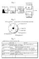
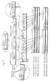
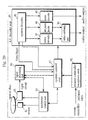
Fig. 1 shows moving pictures 1-5 of the detective story, which are arranged
according to the order of reproduction. In moving picture 1, a detective enters a room. In
moving picture 2, a pen and glasses on a desk is zoomed in for close-ups. In moving
picture 3, a menu is displayed, asking the user to select either "1: glasses" and "2: a pen".
In moving picture 4, glasses are zoomed in for close-ups according to the selection of "1:
glasses". In moving picture 5, a pen is zoomed in for close-ups according to the selection
of "2: a pen".
-
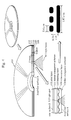
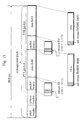
Fig. 2 is an example showing how the respective digital data of moving pictures 1-5
is stored on the video CD. Aside from the digital data, the video CD stores a plurality of
reproduction route data which controls the order of reproduction of moving pictures 1-5.
Digital data for one moving picture is stored in a series of areas. However, the respective
digital data should not necessarily be
stored in a series of areas. They can be stored on different areas of a disc as shown
in Fig. 2.
-
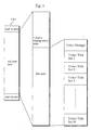
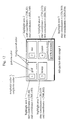
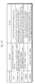
Fig. 3 shows a plurality of reproduction route data stored on the video CD.
There are two types of reproduction route data: one is giving reproduction order to
a plurality of moving picture data; and the other is to switch branch destination as
the reproduction proceeds.
-
The former type is called a "play list", in which the reproduction order of
the moving pictures is designated. Also, the play list includes a piece of link
information which designates the next reproduction route after the reproduction of
the designated moving picture ends.
-
The latter type is called a "selection list". The selection list includes a
plurality of reproduction routs as branch target candidates and a menu address. The
menu address is a record address for a menu image that provides a plurality of
branch targets. The menu image includes a plurality of items whose identification
numbers correspond to identifiers of reproduction routs as the branch targets.
-
In Fig. 3, reproduction route data 1, 3, and 4 are play lists, and reproduction
route data 2 is a selection list. The identification number of each menu item
corresponds to the numeral key on the remote control panel. When the user presses
a numeral key, branch occurs to the corresponding destination.
-
How the video CD in Fig. 2 is reproduced by its reproduction apparatus can
be explained as follows.
-
On designated to start the reproduction, the reproduction apparatus reads the
leading reproduction route data 1 from the optical disc, and stores it into the
internal memory. According to the reproduction order of the moving picture
designated by the reproduction route data 1, the reproduction apparatus determines
the moving picture to be reproduced. After that, the reproduction apparatus moves
a pickup to the position designated by the record address of the moving picture,
and reads the digital data of the moving picture from the optical disc. The
reproduction apparatus converts the digital data into a picture output signal and an
audio output signal through a certain signal process, then outputs the signals to the
display end speaker.
-
After the above processing, the scene of moving picture 1 is reproduced for
a few seconds: a detective is entering a room in which a desk is placed. When the
reproduction of moving picture 1 ends, reproduction of moving picture 2 starts.
The desk is zoomed in for close-ups and the pen and glasses are displayed for a
few seconds. When all motion pictures stored in the reproduction route data are
reproduced, by referring to the link information of reproduction route data 1, the
reproduction apparatus reads the next reproduction route data through the pickup.
The reproduction apparatus, then, discards the reproduction route 1 and optically
reads the next reproduction data into the internal memory. In the case of the
present example, instead of the reproduction route data 1, the reproduction route
data 2 is stored into the memory. In the present example, as the newly stored
reproduction route data 2 is a selection list, a menu which displays a plurality of
branch destinations is displayed. In this case, moving picture 3 is displayed,
allowing users to select "1: glasses" or "2: pen".
-
When the user presses a numeral key on a remote controller corresponding
to the item in the menu, the reproduction apparatus determines reproduction route
data which is the branch target corresponding to the numeral. After that, the
reproduction apparatus discards the reproduction route 2 and optically reads the
determined reproduction data into the internal memory. In the present example, the
reproduction route data 3 is read into a memory if the user selects item "1;";
reproduction route data 4 if the user selects item "2".
-
The reproduction apparatus continues the reproduction according to the new
reproduction route data stored in the memory. If the reproduction route data 3 is
stored in the memory, moving picture 4, an image of close-up glasses, is
reproduced. If the reproduction route data 4 is stored in the memory, moving
picture 5, an image of close-up pen, is reproduced.
-
When the reproduction apparatus continues the above mentioned operations
to the optical disc, moving pictures are reproduced, with the route being changed
according to the user's selection of the menu item. As the user can control the
direction of the interactive software in a various way, he/she can get the feel of
being the detective in the story.
The Task That the Present Invention is going to Solve
-
However, the interactive application mentioned above has the following
shortcomings.
(1) Response in Interaction
-
In order to realize a branch of a video CD, the optical pickup alternatively
has to read the moving pictures and the reproduction route data: e.g. moving
picture 2, reproduction route data 2, moving picture 3, reproduction route data 3 or
4, moving picture 4 or 5. Switching the readout of the moving picture and
reproduction route data entails seek of the pickup, which causes interruption in the
course of reproduction of the program. Especially, if the branch should occur many
times, response of the interactive reproduction deteriorates greatly, which makes
the interactive application less appealing to the user.
-
As mentioned above, it has been difficult to realize a responsive interactive
application so that the smooth reproduction of the program is kept going.
(2) A Menu
-
If the user does not designate the selection item on the menu screen (branch
point of the reproduction), it creates a pause in the course of reproduction. In the
case of the foregoing story of the dragon and the sword, the moment the dragon
appears above the horizon, a menu of "Get Away" and "Fight" is displayed. Here,
if the user has some hesitation to determine which course to take, the reproduction
is paused. Like this, according to the conventional interactive software, normal
reproduction was not realized unless the user does not get devoted to the pursuit of
the story or he/she cannot select the direction of the story at the branch point.
SUMMARY OF THE INVENTION
-
It is an object of the present invention to provide a multimedia optical disc
and a reproduction apparatus for the disc which can achieve highly-responsive,
highly-interactive, and efficient reproduction of an application using simplified
menu operation by the user. In other words, smooth reproduction of the application
keeps going by the user's simple and proper operation depending on the contents of
the application when branch should occur.
-
It is another object of the present invention to provide a multimedia optical
disc and a reproduction apparatus for the disc which realize the best operation that
satisfies the user's preference or wish depending on the contents of the story or the
scenes at the points of branching.
-
The objects can be achieved by the optical disc characterized by the
following constructions.
- (1) A multimedia optical disc comprising a data area for storing at least one
object that has sub-picture data and moving picture data, wherein the data area
includes a plurality of small areas, each of which includes a first sub-area and a
second sub-area, with the object in the data area being stored over consecutive
small areas; the first sub-area stores the moving picture data having a certain time
period and the sub-picture data being reproduced at the same timing as the moving
picture data, the sub-picture data being a menu image which includes a plurality of
buttons for showing menu items for display; and the second sub-area stores control
information including button control data for responding to a user's operation
applied onto a menu image reproduced in the first sub-area in the same small area
and auxiliary control data for substituting the user's operation applied onto the
menu.
According to the above construction, as the video object comprises the sub-picture
data for showing the menu including a plurality of buttons, the button
control data and the auxiliary control data by the small area, high responsiveness
and excellent interactiveness can be realized by the unit of small area. Also,
efficiency of reproducing the interactive application improves as the auxiliary
control data can substitute for the user's operation by the unit of small area.
- (2) The button control data may include a selection color for coloring one of
the buttons in a selected state, an activation color for coloring one of the buttons in
an activated state, and a command for each button, the command being executed
when the button is placed into an activated state; and the auxiliary control data may
include an end time of the user's operations applied onto the menu and forcedly
activating button information showing a button which should be forcedly placed
into the activated state at the end time.
According to the above construction, even if the button is not activated by
the user's operation at the point of branching during reproduction, the reproduction
of the application keeps going in accordance with the intention of the application
creator due to the forcedly activated button information. Then, even if the user is
not used to an interactive application, the reproduction continues automatically.
Moreover, the reproduction apparatus can reproduce the application as an
interactive movie or an ordinary movie according to the user's wish.
- (3) The forcedly activated button information may designate at least one of
a button having a specific button number as a forcedly activated button and a
button in the selected state at the end time.
- (4) The button control data may include a selection color for coloring one of
the buttons in a selected state, an activation color for coloring one of the buttons in
an activated state, and a command for each button, the command being executed
when the button is placed into an activated state; and the auxiliary control data may
include automatic activation button information for specifying which button should
be forcedly placed into an activated state when a user's operation for placing the
button into the selected state is applied.
According to the above constructions, by setting the automatic activation
button, it is possible to reduce the two-fold operations of selection and activation
into a single operation. This is especially effective when highly responsive menus
are desired.
- (5) The auxiliary control data may include prohibition information which
shows which buttons should not be inputted with the numeral key by the user; the
prohibition information may be a threshold; and input with the numeral key by the
user may be prohibited regarding the buttons having greater button number than
the threshold.
According to the above construction, by setting two types of buttons, one of
which can be selected by numerals and the other cannot, misoperations by the user
can be prevented. Moreover, numeral keys and arrow keys can be jointly used
depending on the story and scene at the points of branching.
- (6) The sub-picture data in the first sub-areas in a given section of an object
may constitute one still-image to be superimposed with the moving picture data;
and the auxiliary control data may include address information which shows
storage position of the first small area in the given section in order to return to the
original data after branch to another object occurred.
According to the above construction, when a still image like a menu image
is stored by the leading sub-picture data in a given section and the still image is
still being reproduced in the small area afterwards, it is possible to resume the
reproduction from the original sub-picture data after temporarily calling other
video data.The foregoing objects can be achieved by the reproduction apparatus
characterized by the following constructions.
- (7) A reproduction apparatus for reproducing a multimedia optical disc
comprising a data area for storing a plurality of objects, each having sub-picture
data and moving picture data, wherein the data area may include a plurality of
small areas, each of which includes a first sub-area and a second sub-area, with the
object in the data area being stored over consecutive small areas; the first sub-area
may store the moving picture data having a given time period and the sub-picture
data being reproduced at the same timing as the moving picture data, the sub-picture
data being a menu image which includes a plurality of buttons for showing
menu items for display; and the second sub-area may store control information
including button control data for responding to a user's operation applied onto a
menu image reproduced in the first sub-area in the same small area and auxiliary
control data for substituting the user's operation applied onto the menu, the
reproduction apparatus comprising: a readout device for reading data on the
multimedia optical disc; a reproduction device for reproducing the moving picture
data and sub-picture data in the first sub-area read by the readout device and
outputting the moving picture data and sub-picture data as a video signal for
display; a reception device for receiving a user's operation applied onto the menu
by the sub-picture data; a first control device for responding to the user's operation
according to the button control data read from the second sub-area by the readout
device; and a second control device for substituting for the user's operation
according to the auxiliary control data read from the second sub-area by the
readout device.
According to the above construction, as the video object comprises the sub-picture
data for showing the menu including a plurality of buttons, the button
control data and the auxiliary control data by the unit of small area, the first control
device achieves highly-responsive, highly-interactive, and excellent reproduction
by the small area. Also, efficiency of reproducing the interactive application
improves as the second control device can substitute for the user's operation
according to the auxiliary control data by the unit of small area.
- (8) The forcedly activating device may place the button into the activated
state if the forcedly activated button information shows the button number, and
may place the button in the selected state into the activated state at the end time if
not so.
According to the above construction, even if the button is not activated by
the user's operation at the point of branching during reproduction, the timer device
and the forcedly activating device reproduce the application in accordance with the
intention of the application creator due to the forcedly activated button
information. Then, even if the user is not used to an interactive application, the
reproduction continues automatically.
- (9) The auxiliary control data may include automatic activation button
information which specifies a button forcedly placed into the activated state when
the user's operation for placing the button into the activated state is applied, the
first control device comprising: a holding device for holding button number,
selection color, activation color, command for each button, end time, and forced
button number by analyzing control information every time the second sub-area is
read by the readout device; a button control device for controlling change of state
of each button according to the user's operation received by the reception device; a
button display control device for instructing the reproduction device on the
selection color and the activation color of the button on the menu image; and an
execution device for executing the command of the button placed into the activated
state, and the second control device comprising a "selected=activated" device for
placing the button placed into the selected state from the non-selected state by the
button control device into the activated state.
According to the above construction, by setting an automatic activation
button, it is possible to reduce the two-fold operations comprising selection and
activation into a single operation.
- (10) The auxiliary control data may include prohibition information that
shows which buttons should not be inputted with the numeral key by the user, and
the second control device comprising a prohibition device which prohibits change
to the selected state by the button control means if the numeral key is related to the
prohibition by the prohibition information when the user's operation received by
the reception device is operating a numeral key.
According to the above construction, by setting two type of buttons, one of
which can be selected by numerals and the other cannot, misoperations by the user
can be prevented. Moreover, numeral keys and arrow keys can be jointly used
depending on the story and scene at the points of branching.
- (11) The sub-picture data in the first sub-areas in a given section of the
object may constitute a still image to be superimposed with the moving picture
data; and the auxiliary control data may include address information which shows
storage position of the first small area in the given section in order to return to the
original data after branch to another object occurred, the first control means
comprising: a holding device for holding button number, selection color, activation
color, command for each button, end time, and forced button number by analyzing
control information every time the second sub-area is read by the readout device; a
button control device for controlling change of state of each button according to
the user's operation received by the reception device; a button display control
device for instructing the reproduction device on the selection color and the
activation color of the button on the menu image; and an execution device for
executing the command of the button placed into the activated state, and the
second control means comprising: a detection device for detecting that the user's
operation received by the reception device is a designation of temporary
reproduction of another object; a call device for storing the address information
and designates the reproduction device to reproduce another object when the
reproduction designation is detected; and a resume device for resuming
reproduction of the object based on the stored address information after the
reproduction of another object is completed.
According to the above construction, when a still image like a menu image
is stored by the leading sub-picture data in a given section and the still image is
still being reproduced in the small area afterwards, it is possible to resume the
reproduction from the original sub-picture data after temporarily calling other
video data.The foregoing objects can be achieved by the reproduction method of the
following construction.
- (12) A reproduction method for reproducing multimedia data comprising a
plurality of objects, each having sub-picture data and moving picture data, wherein
the multimedia data may include a plurality of small data, each of which includes a
first sub-data and a second sub-data, with the object being constructed over
consecutive small data; the first sub-data may include the moving picture data
having a given time period and the sub-picture data being reproduced at the same
timing as the moving picture data, the sub-picture data being a menu image which
may include a plurality of buttons for showing menu items for display; and the
second sub-data may include control information including button control data for
responding to a user's operation applied onto the menu image reproduced in the
first sub-data in the same small area and auxiliary control data for substituting the
user's operation applied onto the menu, the reproduction method comprising the
steps of: inputting the multimedia data via a data obtaining unit; making a decoder
reproduce the moving picture data and sub-picture data in the inputted first sub-data
and outputting the moving picture data and sub-picture data as a video signal
for display; receiving the user's operation applied onto the menu by the sub-picture
data; first controlling the data obtaining unit and the decoder so that the
reproduction apparatus responds to the received user's operation according to the
button control data in the inputted second sub-data; and
second controlling the data obtaining unit and the decoder so that the
reproduction apparatus substitutes for a given user's operation according to the
auxiliary control data in the inputted second sub-data. -
-
According to the above construction, as the video object comprises the sub-picture
data for showing the menu including a plurality of buttons, the button
control data and the auxiliary control data by the unit of small area, the first control
device realizes high responsiveness and excellent interactiveness by the unit of
small area. Also, efficiency in reproducing the interactive application improves as
the second control device can substitute for the user's operation according to the
auxiliary control data by the unit of small area.
BRIEF DESCRIPTION OF THE DRAWINGS
-
These and other objects, advantages and features of the invention will
become apparent from the following description thereof taken in conjunction with
the accompanying drawings which illustrate a specific embodiment of the
invention. In the drawings:
- Fig. 1 shows moving pictures 1-5 of a detective story, which are arranged
according to the order of reproduction in the conventional art;
- Fig. 2 is an example showing how the respective digital data of moving
pictures 1-5 is stored on the video CD in the conventional art;
- Fig. 3 shows a plurality of reproduction route data stored onto the video CD
in the conventional art;
- Fig. 4 shows an appearance, a cross-section, an enlarged cross section, and
pit shapes of the DVD;
- Fig. 5 shows the entire data construction stored onto the DVD.
- Fig. 6 shows internal construction of each Video Title Set in Fig. 5;
- Fig. 7 shows the data construction of the highlight information in a PCI
packet;
- Fig. 8 shows data format of a video pack;
- Fig. 9 shows data format of an audio pack;
- Fig. 10 sows data format of a sub-picture data pack;
- Fig. 11 shows data format of a management pack;
- Fig. 12 shows an example of a menu image by the sub-picture data;
- Fig. 13 is more detailed hierarchical data construction the management
pack;
- Fig. 14 shows more detailed data construction of the button color
information and button information in the management pack;
- Fig. 15 shows concrete examples of instructions used as button commands,
each command set for each button;
- Fig. 16 shows hierarchical data construction of the Video Title Set
management information in the each Video Title Set in Fig. 5;
- Fig. 17 is for explanation of a PGC;
- Fig. 18 is an appearance of the reproduction system in the present
embodiment;
- Fig. 19 is an example of key arrangement on a remote controller;
- Fig. 20 is a block diagram showing the entire construction of a reproduction
apparatus; Fig. 21 is a block diagram showing construction of a system decoder;
- Fig. 22 is a block diagram showing construction of a system control unit;
- Fig. 23 is a concrete example of a button state transfer table;
- Fig. 24 is a block diagram showing construction of sub-picture image
decoder;
- Fig. 25 is a flowchart showing outline of processing of reproduction control
by the system control unit;
- Fig. 26 is a detailed flowchart of reproduction procedure of a program chain
group in Fig. 25;
- Fig. 27 is a flowchart showing VOB reproduction control processing in Fig.
26;
- Fig. 28 is a flowchart showing outline of highlight processing in Fig. 27;
- Fig. 29 is a more detailed flowchart showing button initial state activation
processing in Fig. 28;
- Fig. 30 is a more detailed flowchart showing highlight display processing in
Fig. 28;
- Fig. 31 is a more detailed flowchart showing highlight end processing in
Fig. 31;
- Fig. 32 is a more detailed flowchart showing button activation processing in
Fig. 31;
- Fig. 33 is a more detailed flowchart showing button state transfer processing
in Fig. 28;
- Fig. 34 is a flowchart showing call and return processing of the system
menu;
- Fig. 35 is an example of an interactive title;
- Fig. 36 is an example of an interactive title;
- Fig. 37 explains a program chain; and
- Fig. 38 is a flowchart showing production method of an optical disc.
-
DESCRIPTION OF THE PREFERRED EMBODIMENT
Physical Construction of the Multimedia Optical Disc
-
Physical construction of the multimedia optical disc (hereinafter referred to
as DVD: Digital Video Disc) of the present embodiment can be explained as
follows. Fig. 4 shows an appearance, a cross-section, an enlarged cross-section,
and pit shapes of the DVD.
-
The DVD has a diameter of 120mm, which is the same size as CDs.
-
Starting from the bottom, DVD 107 is formed of a first transparent substrate
108 of 0.6mm in thickness, an information layer 109 which is made of a reflective
film like a metal thin film, a binding layer 110, a second transparent substrate 111,
and a print layer 112 on which a label is printed.
-
The print layer 112 is not a requisite for the DVD 107. The second
transparent substrate 111 can be unprotected.
-
The lower surface of the DVD 107 is a read-out surface A: a light beam 113
is shone onto it so that information is reproduced. The upper surface of the DVD
107 is a rear surface B, which is formed by the print layer 112.
-
As shown in Fig. 4, the surface of the first transparent substrate 108 in
contact with the information layer 109 has pits and projections. Information is
stored by changing the length and interval of the pits. In other words, the
information layer 109 has the pits and projections. The length of a pit ranges from
0.4 mu m to 2.13 mu m. A whole series of pits form a spiral track with a radial
distance of 0.74 mu m. Compared to the conventional CDs, the length of pits are
shorter and truck pitch is narrower, thereby increasing the storage density.
-
The read-out surface A is flat. The second transparent substrate is a
reinforcer of the same material as the first transparent substrate 108, having 0.6mm
thickness.
-
The light beam 113 from a light head (not illustrated) passes through the
read-out surface A and it is focused onto the information surface 109. The point of
the focus is then called the light spot 104. As the phase of the reflection of the pit is
different from that of the non-pit areas, reflection ratio decreases as a result of the
optical interference. As the interference does not occur in the non-pit areas,
reflection ratio increases. Due to the change of the reflection ratio, information is
reproduced.
-
The light spot 114 on a DVD has a diameter of around 1/1.6 times the
diameter of a light spot on the foregoing conventional CDs due to the large
numerical aperture NA of the objective lens and small wavelength lambda of the
light beam.
-
The DVDs of the physical construction described above can store about
4.7GB of information on one side, which is almost eight times the storage capacity
of the conventional CDs.
Data Construction the DVD
-
The whole data construction stored on the DVD can be explained as
follows.
-
Fig. 5 shows the entire data construction of the DVD: a spiral track reformed
into a rectangle. As is apparent from this figure, the data is composed of a
lead-in area, volume area, and lead-out area arranged from the center to the edge of
the disc. The lead-in area stores operation stabilization data which is used when the
DVD player starts reading data from the optical disc. The lead-out area informs the
reproduction apparatus of the end of reproduction of the data. The volume area
stores various data which make up an application: physically speaking, it is
composed of a lot of logical blocks (sectors) in the shape of a spiral track on the
disc. Each logical block is 2KB and is identified by its block number (sector
address). This logical block size is the minimum read unit of the reproduction
apparatus.
-
The volume area includes a volume management area and a file area.
-
For the volume management area, blocks that are necessary for management
of the entire disc is allocated. Conforming to ISO (International Standards
Organization) 13346, the volume management area stores information showing the
relation between a plurality of file names and addresses of groups of logical
blocks.
-
The file area stores one Video Manager and at least one Video Title Set. In
the present embodiment, the Video Manager and the Video Title Set are treated as
one file, respectively, as it is convenient for explanation; actually, they are stored
in the consecutive files on the track. The reason can be explained as follows. In the
case of storing movies, as the file capacity becomes too large, it is preferable to
divide the information into a plurality of consecutive files in order to realize easy
management of the reproduction apparatus.
-
Each Video Title Set stores a Title Set. More specifically, it stores a
plurality of video objects (VOBs), each showing fragments of the moving picture,
audio, and still picture of an application such as an interactive movie; and
reproduction management information. An example of the Title Set is a general
term of a movie application in which three versions of the same movie are
included, namely, an original cutting version, a theater version, and a TV version.
In this case, many VOBs are shared by each of the three version and some VOBs
are specific to any of them. The Video Title Sets store both types of VOBs. Due to
the large storage capacity of about 4.7Gbyte, the DVD can store a plurality of
Video Title Sets so that a plurality of interactive applications can be stored such as
movies and interactive movies.
-
The Video Manager manages the entire disc: specifically, a plurality of
VOBs and reproduction management information are stored. The data construction
of the Video Manager is the same as that of the Video Title Set. However, the
Video Manager is used for special purposes. Specifically, the Video Manager
manages Title Sets of the entire disc. Therefore, the Video Manager stores a
VOB/VOBs for system menu for selecting the Title Set desired by the user at the
outset of the reproduction or setting/changing reproduction management of the
Title Set of the entire volume.
Data Construction of the Video Title Set (Part 1)
-
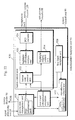
Fig. 6 shows the internal construction of each Video Title Set shown in Fig.
5. The Video Title Set includes a set of Video Objects (VOBs) and the Video Title
Set management information that manages the reproduction route of the Video
Objects (VOBs).
-
The VOB set is composed of all VOBs of a Title Set; that is, VOBs shared
by a plurality of titles and VOBs specific to some of the titles. Each VOB is
composed of the following data which is performed interleaved: moving picture
data (video) of a given time unit, which is called GOP (Group of Picture); a
plurality of audio data to be reproduced along with the moving picture; a plurality
of sub-picture data to be reproduced along with the moving picture; and a
management pack for managing all the foregoing data. As shown in Fig. 6, a VOB
Unit (hereinafter referred to as VOBU) consists of a management pack, moving
picture data which corresponds to the GOP, a sets of audio data, and a sets of sub-picture
data. The sets of audio data and the sets of sub-picture data are selectively
reproduced by the reproduction apparatus.
-
A set of audio data "Audio A", "Audio B", and "Audio C" can store
different kinds of audio: such as voices of different languages such as Japanese and
English; and female voice and male voice.
-
A set of sub-picture data "SP A", "SP B", are still pictures that are
superimposed along with the moving picture. For example, subscripts of different
languages can be stored. Other than the subscripts, menus are another important
use of the sub-picture data. Therefore, at least a set of the sub-picture data can be
used for storing the menu image of an interactive application.
-
The management pack has 2KB data. It stores information which manages
data of each VOBU. The management pack includes highlight information for
managing the button display in the menu image of the sub-picture data and menu
operations. Coupled with the menu image by the sub-picture data, this highlight
information enhances the user's feeling of interactiveness on a VOBU basis.
Data Construction of VOB
-
Fig. 7 shows more detailed data construction of a VOB. It shows how
different kinds of material data are multiplexed into a VOB by interleaving.
-
The elementary streams (1)-(6) are material data to be multiplexed into a
VOB.
-
The elementary stream (1) is a moving data compressed in accordance with
MPEG 2, and it is multiplexed into each VOBU on a GOP basis by interleaving.
Here, the GOP is a compressed moving picture data of about 0.5 second including
at least I picture (Intra picture). A GOP is stored in a VOBU.
-
The elementary streams (2)-(4) are audio data (audio A-C channels), each
corresponding to the moving picture data mentioned above. Part of each audio
channel which almost corresponds to the GOP of moving data in terms of time is
stored into the same VOBU as the moving picture.
-
The elementary streams (5)-(6) are sub-picture data (sub-picture A, B
channel) corresponding to the above moving data. Part of each sub-picture data
corresponding to the GOP of the moving picture data is stored into the same
VOBU as the moving picture data.
-
In the multiplexed VOB, each of "video 1", "audio A-1", "audio B-1", ...
"SP A-1", and "SP B-1" is stored as a collection of 2KB packs. For example,
"video 1" is stored as a collection of packs corresponding to one GOP. The reason
of the packing is that the size is the same as the logical block (sector) of 2KB of
DVD and it is the minimum read unit of the reproduction apparatus.
Data Format of Each Pack
-
The following is more detailed explanation on data format of each pack and
management pack that constitute the moving picture data, audio data, and sub-picture
data in the VOBU.
-
Each pack shown in Figs. 8-11 includes one packet called PES (Packetized
Elementary Stream). Each pack consists of a pack header, a packet header, and a
data field, having 2KB. As to the pack header and the packet header, points
stipulated by MPEG are omitted here. Only information on identifying types of the
pack is explained. According to the present embodiment, in order to identify the
audio data, sub-picture data, and management pack, special packets are used. They
are stipulated by MPEG 2 as private packets 1 and 2. A private packet is a packet
whose contents can be defined in any way. In the present embodiment, the private
packet 1 is defined as audio data and sub-picture data; and private packet 2 is
defined as a management pack.
-
Fig. 8 shows the data format of the pack which will be the constituent of
video 1 of Fig. 7 (hereinafter referred to as video pack). The video pack includes a
pack header, a packet header, and a data field in which a part of the GOP is
written. The stream ID (for example "1110 000") in the packet header is the
representation of the video pack.
-
Fig. 9 shows the data format of the pack which will be the constituent of
"audio A-1" in Fig. 7 (hereinafter referred to as audio pack). The audio pack
includes a pack header, packet header, and data field in which audio data is written.
Stream ID "1011 1111" of the packet header represents the private packet 1. In the
sub-stream ID "10100XXX, 1000XXX" in the data field, the upper five bits shows
audio data and the coding method, and the lower three bits shows which channel is
used.
-
Fig. 10 is a data format of the pack which is the constituent of "SP A=1" in
Fig. 7 (hereinafter referred to as sub-picture pack). The audio pack consists of the
pack header, packet header, and data field in which audio data is written. The
stream ID "1011 1101" represents the private packet 1. In the sub-stream ID of the
data field "10100XXX, 1000XXX", the upper three bits show sub-picture data and
coding method, and the lower five bits show which channel is used.
-
Fig. 11 is the data format of the management pack. The management pack
comprises a pack header, PCI packet (Presentation Control Information Packet),
DSI packet (Data Search Information Packet). The data stream ID "1011 1111" of
the packet header shows private packet 2. In the data field, the sub-stream ID
"0000 0000" represents PCI packet, and the sub-stream ID "0000 0001" represents
DSI packet.
-
In the DSI packet, sets of information is stored for managing
synchronization of the moving picture information and audio information, and
information for realizing special reproduction, such as fast-forwarding and
rewinding. Such information sets include return address information showing a
start position of VOBU which includes the outset of the sub-picture data. The
return address is used in order to resume reproduction of the application after
branch to the system menu caused by the user's pressing down a MENU key on a
remote controller in the course of the reproduction of the application. In the system
menu, the audio streams and sub-picture streams can be switched.
-
The PCI packet stores the highlight information for realizing interaction
between the application and the user. The highlight information includes
management information for responding to the user's operation when the menu
image is reproduced by the sub-picture data in the same VOBU, and auxiliary
management information for substituting the user's operation for the menu. Here,
the user's operation is performed by using cursor keys (arrow keys), ten keys, enter
key on the remote controller of the reproduction apparatus. More specifically, the
highlight information can be explained by means of the menu image example in
Fig. 12. In this menu image, the following five menu items are displayed: 1-golf;
2-ski; 3-tennis; 4-canoe; go to the next menu. The highlight information for this
menu image includes that there are five buttons and that the management
information showing each button's selection color and activation color, and
commands to be executed when each button is activated. In addition to that, as
auxiliary management information mentioned above, the highlight information
includes management information showing a button to be forcedly activated when
the user's operation is not applied, buttons to be activated at the same time
selection occurs, and a button by which selection by the ten key is prohibited.
Data Construction of the Management Pack
-
Fig. 13 shows more detailed hierarchical data construction of the
management pack. Fig. 11 shows that the management pack has a PCI packet and a
DSI packet. As is already explained, PCI includes highlight information.
Outline of Data Construction of the Highlight Information
-
In Fig. 13, highlight information in the PCI includes: highlight general
information, button color information for changing the display color of the button
in the menu, and button information for defining contents of each button. Here, the
highlight display is a kind of display by which the button selected or activated out
of the menu buttons appear in a different color. This makes it possible to realize a
menu display according to the user's operation state.
Detailed Data Construction of the Highlight Information
-
As shown in Fig. 13, the highlight general information includes a highlight
state, highlight start time, highlight end time, button selection end time, all button
number, numeral selection possible button number, forcedly selected button
numbers, and forcedly activated button number. The highlight state shows the
following: whether a button exists or not in the video display section (VOBU) of
about 0.5 second targeted by the PCI packet, and if so, whether the content is the
same as the one of the highlight information of the preceding PCI packet.
-
For example, the highlight state is shown by the following two bits.
-
The highlight state "00" means that a button on the menu does not exist in
the video display area of the VOBU.
-
The highlight state "01" means that a new button exists.
-
The highlight state "10" means that the button is the same as the one of the
preceding VOBU.
-
The highlight state "11" means that the button is the same as the one of the
preceding VOBU except for the highlight command.
-
The highlight start time, highlight end time, and button selection end time
show the start time of the highlight display, end time of the highlight display, and
end time by which the button selection is possible, respectively. These times start
from the reproduction start time of the VOB. In the reproduction apparatus, as the
standard clock for the entire reproduction operation, system time is measured, with
the beginning being the reproduction start time of the VOB. Due to such times, the
reproduction apparatus can synchronize the display of the menu image by the sub-picture
data and the highlight display for the menu display.
-
All button number show the number of buttons being used, which is up to
36. Each button is assigned a button number out of that numeral range.
-
The numeral selection possible button number allows selection of numerals
under the following condition: for example, when "j" is set, selection is allowed
only when numerals between the range from 1 to j are inputted; in other words,
regarding buttons having the number above j, selection by the numeral key is
prohibited.
-
The forcedly selected button number shows that the initially selected button
when the highlight display starts. When the forcedly selected button number is "0"
meaning "invalid", it means the forcedly selected button does not exist at the initial
stage. In that case, the selected button number stored in the reproduction apparatus
is used.
-
The forcedly activated button number shows the button number which
should be automatically activated when none of the buttons are selected when the
button selection possible section ends. The numeral "63" and "0" are magic
numbers that are not button numbers. In other words, "0" means not specified
(invalid) as well as the forcedly selected button number, and "63" means the
forcedly activated button which is in the selected state at the button selection end
time without specifying a specific button number. In this way, the menu used in the
interactive movie application makes it possible to continue the reproduction
without causing interruption even if there is no user's activation.
Detailed Data Construction of the Button Color Information
-
Fig. 14 shows detailed data construction of the button color information and
button information.
-
The button color information includes button color information 1, button
color information 2, and button color information 3. Three types of button colors
are prepared for each button on the menu and one of them is activated for each
button. In the present embodiment, the number of usable buttons is 36 at the most.
As it is not efficient to allocate different colors to all the buttons, each button is
allocated one of the button color information 1, button color information 2, and
button color information 3.
-
Each of the button color information 1-3 comprises selection color
information and activation color information.
-
The selection color information shows colors to be displayed when a button
is selected by an arrow key (the button is in the selected state). The selection color
information includes an emphatic color code 1, emphatic color code 2, pattern
color code, and background color code. Fig. 12 shows how the four colors are
employed. Suppose that "4-canoe" button is in the selected state. The box
enclosing "4" is displayed by the emphatic color code 1. The box enclosing "4-canoe"
is displayed by the emphatic color code 2. The letter of "4-canoe" is
displayed by the pattern color code. The background of the letter is displayed with
the background color.
-
The activation color information shows a color to be displayed when the
button in the selected state is put into the activated state. As well as the selection
color information, the activation color information consists of the emphatic color
code 1, emphatic color code 2, pattern color code, and background color code.
-
How each color code and menu button correspond to each other can be
explained as follows.
-
The menu image by the sub-picture data is image data, each pixel being two
bits. The two-bit code of each pixel designates one of the emphatic color 1,
emphatic color 2, pattern color, and background color. The following is an
example of a bit assignment.
-
The two bit code "00" shows background color (pixels of the background).
-
The two bit code "01" shows pattern color (pixels that constitute characters).
-
The two bit code "10" shows emphatic color 1 (a box enclosing the button,
one of the double boxes).
-
The two bit code "11" shows emphatic color 2 (The other of the double
boxes).
-
The emphatic color code 1, emphatic color code 2, pattern color code, and
background color code in the button color information are used for converting the
2-bit-code specified for every pixel of the sub-picture data into the actual color
data specified by the 24 bits. More specifically, the empathic color code 1,
emphatic color code 2, pattern color code, and background color code are four-bit
code, respectively, (hereinafter referred to as four bit color code) and specifies one
of the 16 colors. In other words, the emphatic color code 1, emphatic color code 2,
pattern color code, and background code are four bit code, respectively, for
converting the 2-bit-code specified for each pixel (possible to separate four types
of colors) into one of the 16 colors. These four bit codes are further converted into
24-bit color code by the color conversion table in the reproduction apparatus
during reproduction.
Detailed Data Construction of the Button Information
-
As shown in Fig. 14, the button information stores information
corresponding to the button 1-36 information (maximum 36). For the explanatory
convenience, each of the buttons 1-36 information will be represented by button n
information.
-
The button n information includes button position information, neighboring
button information, and button command.
-
The button position information includes a button color number, start X-Y
coordinates, end X-Y coordinates, and "selected=activated" flag.
-
The button color number specifies which of the button color information 1-3
should be employed.
-
As shown in Fig. 12, start X-Y coordinates, end X-Y coordinates show top
left coordinates and bottom right coordinates of a rectangular, respectively, for
specifying a highlight area. Both coordinates show the range of button to be
colored according to the selection color information and activation color
information.
-
The "selected=activated" flag shows, when the button is selected, whether
the button should be placed into the activated state or not. Instead of user's pressing
down the ENTER key, this flag reduces the number of the user's key input. The
moment the button is selected by an arrow key, the button is activated without
user's further pressing down the enter key.
-
The neighboring button information shows other button numbers that exist
above, below, and on both sides of the corresponding button. Due to the
neighboring button information, the reproduction apparatus can move the button
selection by operating the arrow key.
-
The button command stores the commands to be executed when the button
is in the activated state. The examples are an instruction for designating branch and
an instruction for designating operations for the register inside the reproduction
apparatus.
Details of the Button Command
-
Fig. 15 shows examples of instructions used as button commands set for
every button in the button information. Each instruction is composed of operation
code and at least one operand.
-
In Fig. 15, the "Link" instruction designates a branch reproduction to the
program chain (PGC) designated by the operand. Here, the program chain (PGC) is
a string of the VOBs to be reproduced successively or a reproduction route of the
VOBs. The details of PGC will be explained later.
-
The "CmpRegLink" instruction having a register number, an integer, a
branch condition and a branch destination PGC number as operands instructs to
branch to the PGC occurs only when the register value satisfies the branch
condition for the integer. Branch conditions are =(equal), >(larger), <(smaller).
-
<#s> The "SetRegLink" instruction having a register number, an integer, an
operation content, and a branch destination PGC number as operands instructs to
branch to the PGC after storing the value obtained by operating the register value
and the integer into the register. Here, the operands that show operation contents
are =(substitution), +(plus), -(minus), *(multiplication), /(division),
MOD(modulus), AND (logical product), OR (logical sum), XOR(exclusive OR).
-
The "SetReg" instruction having a register number, an integer, and an
operation contest as operands instructs to store the operation-performed register
number and integer into the register. Here, the operand that shows the operation
content is the same as that of the "SetRegLink" operation.
-
The "Random" operation having a register number and an integer instructs
value as operands instructs to generate an integral random number from 1 to the
integer value to be stored into the register.
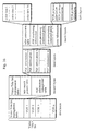
Data Construction of the Video Title Set (Part 2)
-
The Video Title Set management information can be explained as follows,
which manages the reproduction route of the VOB.
-
Fig. 16 shows hierarchical data construction of the Video Title Set
management information of each Video Title Set in Fig. 5. From left to right, the
sets of layers are referred to as the first layer to the fifth layer, respectively.
-
The first layer is already explained in Fig. 6.
-
As is shown by the second layer, the Video Title Set management
information includes a Video Title Set management table, title search pointer table,
and PGC information table.
-
The Video Title Set management table is the header information of the
Video Title Set, and stores pointers that show storage position of the PGC
information management table and the title search pointer table.
-
The title search pointer table is an index of the PGCs stored in the PGC
information management table, and stores pointers for the storage position of the
PGC which should be executed firstly for each title, for example, a pointer which
shows the storage position of the PGC information that shows the leading PGC of
the interactive movie.
-
The PGC information management table is a table for reproducing a given
VOBs in a given order from the VOBs stored in the Video Title Set. The PGC
information management table manages by the unit called PGC in which VOBs are
combined according to a given order. Fig. 17 shows the PGC. In this figure, the
PGC#1 shows the reproduction route from the VOB#1 to VOB#2 in the Video
Title Set. The PGC#7 shows he reproduction route from the VOB#15 to VOB#14
via VOB#13.
-
In order to realize this, as shown in the third layers in Fig. 16, the PGC
information management table comprises the PGC information #1-#m. Each PGC
information specifies construction of one PGC and designates the PGC to be
reproduced next.
-
As is shown by the fourth layers in Fig. 16, each PGC information
comprises a color conversion table, PGC connection information, pre-processing
command group, post-processing command group, and route information.
-
The route information is, as shown by Fig. 5, comprises a set of VOB
position information, and they are arranged according to the order of reproduction.
For example, the route information of the PGC#1 in Fig. 17 consists of the VOB#1
position information and VOB#2 position information. The position information
includes the logical address of the leading sector of the VOB and all the sector
numbers occupied by the VOB.
-
The post-processing command group shows commands to be executed after
the reproduction of the PGC. This command can be used as the button command in
the highlight information, which is shown in Fig. 16. For example, in Fig. 17, the
PGC#1 branches to either the PGC#2 or PGC#3. In order to realize this, after the
PGC#1, the "CmpRegLink" instruction may be set to the processing command
group.
-
The pre-processing command group shows commands to be executed before
the reproduction of the PGC starts. This command can also be set the instruction
shown in Fig. 16. For example, the pre-processing command group can be used for
initializing the register by the "SetReg" instruction.
-
The PGC connection information shows one PGC number to be reproduced
next. However, when branch occurs due to a branch instruction (for example,
"CmpRegLink") in the post-processing command group, the PGC connection
information is neglected.
-
The color conversion table is for converting the foregoing four-bit color
code of the sub-picture data into actual color data specified by 24 bits. This color
conversion table, as shown by the fifth layers in Fig. 16, stores 24-bit color code
comprising luminosity data, color difference data 1 and 2; each four-bit-color code
(colors 1-16) corresponding to any of the 24-bit-codes. How to specify the color is
stipulated by ITU-R-Rec. and 601-1.
-
So far, the data construction of the optical disc has been explained. Next,
explanation on the reproduction apparatus starts.
Appearances of the Reproduction System
-
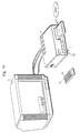
Fig. 18 shows the appearances of the reproduction system, comprising the
reproduction apparatus, a monitor, and the remote controller of the present
embodiment.
-
In this figure, the reproduction apparatus 1 reproduces the foregoing optical
disc (DVD) according to the instruction from the remote controller 91, and outputs
a video signal and audio signals. The instruction from the remote controller 91 is
received by the remote controller reception unit 92 of the reproduction apparatus 1.
-
The display monitor 2 receives a video signal and audio signals from the
reproduction apparatus, and outputs images and audio. This display monitor can be
a common TV monitor.
Appearance of the Remote Controller
-
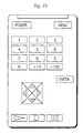
Fig. 19 shows an example of a key arrangement of the remote controller 91.
Here, keys related to the present invention are explained. The MENU key is for
calling the system menu by the Video Manager when some titles of an interactive
movies are reproduced. The Ten keys and direction (arrow) keys are for selecting
menu items. The ENTER key is for activating the selected menu item. Other keys
are the same as those of other AV apparatuses.
Entire Construction of the Reproduction Apparatus
-
Fig. 20 shows the entire construction of the reproduction apparatus shown
in Fig. 18. The reproduction apparatus 1 comprises the motor 81, light pickup 82,
mechanism control unit 83, signal processing unit 84, AV decoder unit 85, remote
controller reception unit 92, and system control unit 93. Furthermore, the AV
decoder unit 85 comprises the system decoder 86, video decoder 87, sub-picture
decoder 88, audio decoder 89, and image combining unit 90.
-
The mechanism control unit 83 controls the mechanical system including
the motor 81 which drives the disc and the light pickup 82 which reads out the
signal stored on the disc. More specifically, the mechanism control unit 83 adjusts
the speed of the motor according to the track position designated by the system
control unit 93, and moves the position of the pickup 82 by controlling the actuator
of the light pickup 82. When the accurate track is detected by servo control, the
mechanism control unit 83 waits during the rotation of the disc until the desired
physical sector comes, and reads the signals successively from the desired position.
-
The signal processing unit 84 performs the following processing on the
signal read from the light pickup 82; amplification, waveform shaping, changing to
binary, decoding, and error correction. After that, the signal processing unit 84
stores the data obtained by the above processing in the buffer memory (not
illustrated) into the system control unit 93. In the buffer memory, Video Title Set
control information of the data is held in the system control unit 93, and the VOB
of the data is transferred to the system decoder 86 by the system control unit 93.
-
The AV decoder 85 converts the VOB to the original video signal, audio
signal, and sub-picture signal.
-
The system decoder 86 judges the stream ID and the sub- stream ID in each
logical block (data) included in the VOB transferred from the buffer memory. And
the system decoder 86 outputs the video data to the video decoder 87, the audio
data to the audio decoder 89, the sub-picture data to the sub-picture decoder 88,
and the management pack to the system control unit 93. At this time, the system
decoder 86 outputs the audio data and the sub-picture data, each having the number
(channel) designated by the system control unit 93 from the sets of the audio data
and sub-picture data to the audio decoder 89 and sub-picture image decoder 88,
respectively, and discards other data.
-
The video decoder 87 decodes the video data inputted from the system
decoder 86, expands the decoded video data, and outputs the decoded-and-expanded
video data to image combining unit 90 as a digital video signal.
-
The sub-picture data inputted from the system decoder 86 is an image data
which has been performed run-length compression. The sub-picture decoder 88
decodes the inputted sub-picture data, expands the decoded sub-picture data, and
outputs the decoded-and-outputted sub-picture data to the image combining unit 90
in the same form as the digital video signal. The audio decoder 89 decodes the
audio data inputted from system decoder 86, expands the decoded audio data, and
outputs the decoded-and-expanded audio data as a digital audio signal.
-
The image combining unit 90 outputs the video signal in which the output
of the video decoder 87 and output of the sub-picture decoder 88 are mixed
according to the ratio designated by the system control unit 93. This present signal
is converted into an analogue signal and inputted into the display apparatus.
Construction of the System Decoder
-
Fig. 21 is a block diagram showing the construction of the system decoder
86 in Fig. 20. As is apparent from this figure, the system decoder 86 comprises the
MPEG decoder 120, sub-picture/audio separation unit 121, sub-picture selection
unit 122, and audio selection unit 123.
-
The MPEG decoder 120 judges the type of each data pack included in the
VOB stream transferred from the buffer memory by referring to the stream ID in
the pack. If it is the video packet, the MPEG decoder 120 outputs it to the video
decoder 87; if it is the private packet 1, to the sup-picture/audio separation unit
121; if it is the private packet 2, to the system control unit 93, and if it is the MPEG
audio packet, to the audio selection unit 123.
-
The sub-picture/audio separation unit 121 judges the type of the packet by
referring to the sub-stream ID in the pack regarding the private packet 1 inputted
from the MPEG decoder 120. If it is the sub-picture data, sub-picture/audio
separation unit 121 outputs it to the sub-picture selection unit 122; and if it is the
audio data, to the audio selection unit 123. As a result, the sub-picture data and
audio data of all numbers are outputted to the sub-picture selection unit 122 and
audio selection unit 123, respectively.
-
The sub-picture selection unit 122 outputs, out of the sub/picture decoder 88
from the sub-picture /audio separation unit 121, only the sub-picture data having
the number designated by the system control unit 93 to the sub-picture decoder 88.
The sub-picture data of the number other than the designated number are
discarded.
-
The audio selection unit 123 outputs, out of the MPEG audio data from the
MPEG decoder 120, only the audio data having the number designated by the
system control unit 93. And the audio selection unit 123 outputs the audio data
from the sub-picture/audio separation unit 121. The audio data of the number other
than the designated number are discarded.
Construction of the System Management Unit
-
Fig. 22 is the block diagram showing the construction of the system control
unit 93 in Fig. 20.
-
The system control unit 93 comprises the button control unit 930, system
state management unit 935, command interpretation execution unit 936,
reproduction control unit 937, button state control unit 933, and key input
reception unit 938. Furthermore, the button control unit 930 comprises the PCI
decoder 931, highlight information analysis unit 932, and highlight display control
unit 934. According to the highlight information in the management pack, the
button control unit 930 controls response to the user's menu operations.
-
The PCI decoder 931 separates the PCI packet from the management pack
transferred from the MPEG decoder 120, and transfers the highlight information to
the highlight information analysis unit 932. As the management pack is performed
interleaving in each VOBU as shown in Fig. 7, a new management pack is
transferred every 0.5 second.
-
The highlight information analysis unit 932 analyses the highlight
information inputted from the PCI decoder 931, and creates a button state transfer
table showing how the selected state of the button transfers for all buttons on the
menu image by the sub-picture data.
-
The button state control unit 933 stores the button state transfer table
created by the highlight information analysis unit 932, stores the button number in
the selected state (current state) and the button number in the activated state, and
manages the state of change.
-
Fig. 23 shows concrete example of the button state transfer table. This table
is based on the menu image by the sub-picture data shown in Fig. 12.
-
In Fig. 23, "current state" column shows all the buttons that could be in the
selected state. In other words, each of the S1-S5 shows that the button numbers 1-5
on the menu image are in the selected state. The number of the "current state" is
created by the number of all the buttons shown by the highlight information
analysis unit 932 in Fig. 13.
-
The "arrow key transfer information" column shows to which state the
current state transfers when the arrow key of the remote controller is inputted. The
arrow key transfer information is created by the highlight information analysis unit
932 according to the neighboring button information in the highlight information.
-
The "highlight display information" column shows highlight of each button.
The highlight display information is set by the highlight information analysis unit
932 according to the highlight area composed of the start X-Y coordinates and end
X-Y coordinates in Fig. 14.
-
The "numeral key allowance" column shows, for each state, whether the
selection by the numeral key can be allowed. This information is set by the
highlight information analysis unit 932 according to the number of the numeral
selection possible buttons. In the case of Fig. 23, button selection is allowed for the
buttons 1-4, but not for the button 5.
-
The "selected=activated" column shows, for every button, whether the
buttons set in the selected state should be changed to activated state immediately.
This information is set by the highlight information analysis unit 932 according to
the "selected=activated" flag shown in Fig. 14. In the case of Fig. 23, the
"selected=activated" is set for only button 5.
-
The "button color number" column shows button color number of each
button, and this column is set by the highlight information analysis unit 932
according to the button number shown in Fig. 14.
-
The "button command" column shows commands to be executed when each
button is in the activated state. This column is activated by the highlight
information analysis unit 932 according to the button command shown in Fig. 14.
-
According to the button state transfer table, the highlight display control
unit 934 and the command interpretation execution unit 936 manage response to
the user's menu operations.
-
The highlight display control unit 934 controls the highlight display by
notifying the highlight area of the button in the selected state, activated state, and
color information designated by the button color number to the sub-picture decoder
88 according to the button state transfer table.
-
The system state management unit 935 temporarily stores the digital data
inputted from the signal processing unit 84. A part of the buffer area is reserved as
PGC information buffer 935a which stores PGC information. When the digital data
inputted into the system state control management unit 935 is VOB, it is
transferred to the system decoder 86 by the reproduction control unit 937. When it
is PGC information, it is stored in the PGC information buffer 935a.
-
The command interpretation execution unit 936 executes a button command
when the button is put into the activated state.
-
The reproduction control unit 937 having a register set 937a interprets the
key-inputted data from the key input reception unit 938, and controls other
reproduction management. The register set comprises a plurality of registers (R0-R3).
One of the registers store a channel number of the sub-picture data being
reproduced and a channel number of the audio data, and notifies them to the sub-picture
selection unit 122 and the audio selection unit 123, respectively.
-
The key input reception unit 938 receives a key code which designates a key
inputted from the remote controller reception unit 92, and notifies it to the button
state control unit 933 and the reproduction control unit 937.
Detailed Construction of the Sub-Picture Decoder
-
Fig. 24 is a block diagram showing detained construction of the sub-picture
decoder 88. The sub-picture decoder 88 comprises the input buffer 881, sub-picture
code generation unit 882, sub-picture display control unit 883, sub-picture code
conversion table 884, compressed video signal generation unit 885, highlight code
conversion table 886, highlight area management unit 887, sub-picture signal
generation unit 888, and color conversion table 889.
-
The input buffer 881 stores sub-picture data of the channel selected by the
sub-picture selection unit 122 in the system decoder 86.
-
The sub-picture code generation unit 882 converts the image data which has
been performed run-length compression into a bit-map data in which each pixel is
expressed by 2-bit code by expanding.
-
The sub-picture display control unit 883 controls display start/end of image
data; carries out image processing such as color change when karaoke is used; and
generates sub-picture code conversion table 884 by the color information stored in
the sub-picture data.
-
The compressed picture signal generation unit 885 converts the two-bit code
of each pixel outputted from the sub-picture code generation unit 882 into 16 color
code of 4 bits by referring to the sub-picture code conversion table 884 for the sub-picture
part and the highlight code conversion table 886 for the highlight area.
-
The highlight code conversion table 886 is a color conversion table for
converting 2-bit code of the highlight part which is a part of the image data into a
4-bit code.
-
The highlight area management unit 887 stores the start X-Y coordinates
and end X-Y coordinates of the highlight area, and prepares for readout of the
compressed video signal generation unit 885.
-
The sub-picture signal generation unit 888 converts the 16 color code
outputted from the compressed video signal generation unit 885, which is 4 bit per
pixel, into about 16,000,000 color data of 24 bits.
-
The color conversion table 889 stores the 16 color information in the color
conversion table in the PGC information to be reproduced.
-
Outline of Processing Flow of the Reproduction by the System Control Unit
93
-
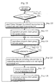
Fig. 25 is a schematic flowchart showing reproduction management by the
system control unit 93 in Fig. 20.
-
In detecting that the disc is set into the reproduction apparatus, the system
control unit 93, by managing the mechanism control unit 83 and the signal
processing unit 84, controls the disc rotation until a stable readout is carried out,
and when the stable readout is carried out, reads out the lead-in area firstly by
moving the light pickup. After that, the system control unit 93 reads the volume
management area, Video Manager in Fig. 5 based on the information in the volume
management area (Steps 121, 122), and reproduces the PGC group for the system
menu (Step 123).
-
According to the user's operations to the system menu, the system control
93 reproduces the PGC for the title menu in the selected Video Title Set (Step
124), based on the user's selection (Step 125), reads the Video Title Set
management information corresponding to the selected title (Step 126), and
branches to the leading PGC of the title (Step 127). Furthermore, after the PGC
group is reproduced and finished, the system control unit 93 goes back to Step 124
(Step 128).
Flow of Reproduction Procedure of the Program Chain Group
-
Fig. 26 is a detailed flowchart of the reproduction procedure of the program
chain group in Step 128 in Fig. 25. The same things apply to Steps 123 and 124 in
Fig. 25.
-
In Fig. 26, the system control unit 93 reads the corresponding PGC
information from the Video Title Set information (Step 131). This PGC
information is stored into the PGC Information buffer 935a.
-
Next, initial setting is carried out according to the PGC information in the
PGC information buffer 935a. Execution of the pre-processing command group
and setting of the color conversion table are included in the initial setting (Step
132). Due to the execution of the pre-processing command group, for example,
initial value of the register is set. The color conversion table shown by the fourth
layers in Fig. 16 is, at this moment, stored in the buffer memory in the system state
management unit 935, and it is transferred to the sub-picture code conversion table
884 in the sub-picture decoder 88 in Fig. 24.
-
After that, the system control unit successively reproduces the position
information specified by the route information in the PGC information buffer 935a,
and manages reproduction of each VOB#i (i=1-n) (Step 133). Specifically, the
system control unit 93 starts reading the VOB for the mechanism control unit 83
and the signal processing unit 84 according to the position information set in the
route information. The read VOB is separated and reproduced by the AV decoder
85. At this moment, the separated video and sub-picture is displayed on the screen
(not illustrated) and the audio output by the audio data is started. If the branch
instruction set as a button command is executed during the reproduction of the
VOB, branch to the PGC specified by the branch instruction occurs (from Step 135
to Step 131). When reproduction of all the VOB is completed, the post-processing
command group is executed (Step 134), and if there is a PGC to be executed next,
it is reproduced (from Step 135 to Step 131). The PGC to be reproduced next is
specified by the branch instruction in the post-processing command group or the
PGC connection information in the PGC information.
Reproduction of the VOB
-
Fig. 27 is a flowchart showing the reproduction management processing of
each VOB (VOB#i) shown by the Step 133#i in Fig. 26.
-
According to the ith position information in the reproduction information,
the system control unit 93 controls the start of the readout from the leading address
of the VOB#i (Step il). After that, the digital data string of the VOB#i is read by
the mechanism control unit 83 and the signal processing unit 84. This digital data
string is successively inputted into the system decoder 86 via the system control
unit 93. The system decoder 86 decodes the digital data string and judges the video
pack, sub-picture pack of any channel, audio-pack of any channel, and
management pack. And the system decoder 86 outputs them to the video decoder
87, sub-picture decoder 88, audio decoder 89, and the PCI decoder 931 in the
system control unit 93, respectively. Then, reproduction of the moving picture,
audio, and sup-picture starts. The management pack is inputted into the decoder
931 every 0.5 second.
-
On being inputted the management pack (Step i2), according to the
highlight state shown by Fig. 13, the PCI decoder 931 judges whether new
highlight information is set in the management pack (Step i3), and if it is new
highlight information, the PCI decoder 931 transfers it to the highlight information
analysis unit 932. The highlight information analysis unit 932 creates the button
state transfer table from the transferred highlight information. The button control
unit 930 carries out the highlight processing in Fig. 28 based on the button state
transfer table (Step i4). Here, the highlight processing means the highlight display
and the interactive management based on the highlight information. Moreover, the
system control unit 93 waits for the input of the management pack if the digital
data string read from the DVD is not the last of the VOB#i (Step i2). In this case,
the above processing is repeated. If it is the last of the VOB, the reproduction of
the VOB#i is completed. After that, the system control unit 93 determines whether
it is the last of the VOB#i or not from the number of all sectors of the VOB#i
included in the position information.
Highlight Processing
-
Fig. 28 is a schematic flowchart showing the highlight processing
mentioned above (Step i4 in Fig. 27)
-
On being transferred the highlight information from the PCI decoder 931,
the highlight information analysis unit 932 analyses the highlight information,
creates the button state transfer table in Fig. 23. and stores it in the button state
control unit 933 (Steps 201, 202). The button state control unit 933 determines the
initial state of the button according to the forcedly selected button number in the
highlight information (Step 203: refer to Fig. 29). Furthermore, the button state
control unit 933 compares the highlight start time and the system time in the
reproduction apparatus. At the highlight start time (Step 204: refer to Fig. 30), the
button state control unit 933 carries out the highlight display processing via the
highlight display control unit 934 (Step 205). After that, until the button selection
end time (Step 205), every time the state transfers according to the user's key
operations (Steps 207 and 208: refer to Fig. 33), the button state control unit 933
carries out the highlight display processing, and ends the processing at the button
selection end time (Step 206, refer to Fig. 31).
Button Initial State Activation Processing
-
Fig. 29 is a more detailed flowchart showing the button initial state
activation processing mentioned above (Step 203 in Fig. 28).
-
After creating the button state transfer table, if the forcedly selected button
number is specified in the highlight information, the button state control unit 933
holds the button number of the current state (Steps 211, 212). If the forcedly
selected button number is not specified, the button state control unit 933 holds any
of the button numbers (for example, the button number held as the selected state)
as the current state (Steps 211, 213).
Highlight Display Processing
-
Fig. 30 is a more detailed flowchart showing the foregoing highlight display
processing (Step 204 in Fig. 28).
-
When the button initial state is determine or the current state changes, the
button state control unit 933 reads the highlight area in the button state transfer
table that correspond to the current state (button selection number) (Step 221), and
sets it in the highlight area management unit 887 in the sup-picture decoder 88 via
the highlight display control unit 934 (Step 222). At the same time, according to
the button color number in the button state transfer table, the button state control
unit 933 sets the selection color information in the highlight code conversion table
886 in the sub-picture decoder 88 via the highlight display control unit 934 (Step
223). In this way, the sub-picture decoder 88 changes the color of the highlight
area of the sub-picture image being displayed.
Highlight End Processing
-
Fig. 31 is a more detailed flowchart showing the foregoing highlight end
processing (Step 06 in Fig. 28).
-
At the button selection end time, the button state control unit 933 checks
whether the forcedly activated button number exists in the PGC information buffer
935a (Step 231). Regarding the forcedly activated button number, if the number is
any of 1-36 and 63, it means that a forcedly activated button number exist; if the
number is 0, a forcedly activated button number does not exist.
-
When the forcedly activated button number is invalid (the value is 0), the
button state control unit 933 erases the highlight display via the highlight display
control unit 934 at the highlight end time (Steps 235, 236).
-
When the forcedly activated button number is valid (the value is other than
0), the button state control unit 933 puts the button into the activated state if a
specific button number from 1-36 is designated, and puts the button in the selected
state into the activated state if the button number 63 is designated (Step 233), and
carries out the button activation processing (Step 234).
Button Activation Processing
-
Fig. 32 is a more detailed flowchart showing the button activation
processing mentioned above (Step 234 in Fig. 31).
-
The button state control unit 933 displays the button in the activated state
with the activation color via the highlight display control unit 934 (Step 241), reads
the button command of the corresponding button from the button state transfer
table and makes the command interpretation execution unit 936 carry it out (Step
242). Furthermore, the button state control unit 933 determines whether branch
should occur or not due to the execution of the button command (Step 243). If that
is not the case (for example, "SetReg", "Random"), the button state control unit
933 ends the button activation processing, and if that is the case (for example,
"Link"), goes to Step 135 in Fig. 26 and branches to other PGC.
Button State Transfer Processing
-
Fig. 33 is a more detailed flowchart showing the foregoing button state
transfer processing (Step 208 in Fig. 28).
-
On being inputted a key code from the key input reception unit 938, the
button state control unit 933 judges the inputted key from the key code ( Steps 251,
254, and 257).
-
When the input key is a numeral key (Step 251), and the "numeral key
allowance" column corresponding to the "current state" in the button state transfer
table is YES (Step 252), the button state control unit 933 holds the number as the
button number of the selected state (Step 253). For example, in Fig. 23, when the
current state is S1 and the numeral key 2 is an input key, the current state is
changed to S2. After changing the selected state, if the "selected=activated"
column is YES, the button state control unit 933 stores the number of the numeral
key as the button number of the activated state (Step 256), and carries out the
button activation processing (Step 258).
-
If the input key is an arrow key (Step 254), the button state control unit 933
fetches the button number of the transfer destination according to the "arrow key
transfer information" in the button state transfer table and stores the button number
as the selected state (Step 255). If the "selected=activated" column is YES, the
button state control unit 933 holds the number of the numeral key as the button
number in the activated state (Step 256), and carries out the button activation
processing (Step 258).
-
If the input key is the activated key, the button state control unit 933 holds
the button number being stored as the current state as the activated button number
(Step 257), and carries out the button activation processing (Step 258).
Call and Return Processing for the System Menu
-
So far, reproduction management processing of the PGC group, especially,
highlight processing, has been explained. Next explanation is about call and return
processing regarding the system menu which is called when the MENU key on the
remote controller 92 is pressed during the reproduction of the PGC.
-
Fig. 34 is a flowchart showing call and return processing for the system
menu.
-
When the MENU key is pressed, the reproduction control unit 937
determines whether the menu by the sub-picture data is being displayed or not
(Step 261). If so, the reproduction control unit 937 stores the return address of the
sub-picture data set in the DSI packet of the management pack into the buffer
memory in the system state management unit 935 (Step 262). Whether the menu
by the sub-picture data is being displayed or not can be determined by judging
whether the system time is within the highlight section (from the highlight start
time to the highlight end time). That is because if the menu image is realized by the
sub-picture data in the VOBU prior to the current VOBU, in order to resume the
current menu display, it is necessary to resume the reproduction from the leading
sub-picture data, not from the sub-picture data in the same VOBU as the current
management pack.
-
If the menu is not being displayed, the reproduction control unit 937 stores
the current VOBU start address into the buffer memory in the system state
management unit 935 (Step 263).
-
Furthermore, the reproduction control unit 937 stores the system state
showing the current reproduction state (Step 263). This system state includes the
button number in the selected state.
-
After that, the reproduction control unit 937 manages the reproduction of
the system menu (Step 265). The management of the reproduction of the system
menu is the same as the one of the PGC group shown in Fig. 26. If the user, again,
presses the MENU key on the system menu being displayed, the reproduction of
the system menu is over. Then, the reproduction control unit 937 returns to the
system state (Step 266), and resumes the reproduction from the return address
(Step 267).
Operations
-
The operations of the multimedia optical disc and its reproduction apparatus
can be explained as follows.
Example of a Forcedly Activated Button
-
Here is an example of an operation in which forcedly activated button is
used. Fig. 35 is a title example of an interactive application in which a dragon and
a knight fight with each other. The scene 1 by the PGC#1 shows a display image 1
in which a knight encounters a dragon. The scene 2 by the PGC #2 shows a display
image 2 in which a menu by the sup-picture data is superimposed. The scene 3 by
the PGC#3 shows a display image 3 in which the knight gets away. For the
explanatory reason, also in this example, each PGC is supposed to be one VOB.
-
The sub-picture data in the PGC#2 is a menu image composed of a "1-Fight"
button and a "2 - Get away" button. For the button command of the "1-Fight"
button, "Link" instruction to the PGC (not illustrated) for showing the
fighting scene is set. For the button command of the "2 - Get Away" button, "Link"
instruction to the PGC#3 showing the scene 3 is set. Furthermore, in this example,
"63" is set as the forcedly activated button in Fig. 13. The forcedly activated button
number "63" means that the current button in the selected state is forcedly
activated. If the user does not press the activation key until the button selection
time even if he/she had pressed "2 - Get Away" in the scene 2, the reproduction
control unit 937 places the "2 - Get Away" button in the selected state into the
activated state. Then, scene 3 is reproduced.
-
A title creator can determine which button should be the forcedly activated
button depending on the development of the story, contents of the scene, and menu
items. In the foregoing example, the "activation button" is activated based on the
user's selection state. However, there are cases in which the reproduction can
proceed more effectively if the title creator directly designates the activated button
number.
-
The following is an example, which is shown in the lower row of Figure 35.
The scene 2 by the PGC#2 shows the display image 2' in which a menu is
superimposed, the menu comprising the "1 - Fight" button, "2 - Get Away" button,
and "3 - Do Nothing" button. The scene 3 by the PGC#3 is the branch destination
when the "3 -Do Nothing" button is selected in the PGC#2. What is displayed on
the scene is a dragon coming closer to the knight. If a direction of a story which
should continue after the "3 - Do Nothing" button is desired in the scene 2, what is
necessary is to set the forcedly activated button number for the menu in the PGC#2
as "3". In this way, even if there is no activation operation by the user, the scene 2
changes to the scene 3. As a result, even if the user is not interested in pursuing the
course of story, effective story development can be realized.
-
The next explanation is about the case in which hidden buttons exist other
than the MENU button in the foregoing PGCs#1-#3 in Fig. 35. The hidden buttons
do not necessarily appear on the screen. In all scenes, the same function is
allocated to the hidden button. For example, a map button and status button exist as
hidden buttons. The map button is a button for calling a map of the adventure
world in which the warrior lives. The status button is a button for calling images
which display parameters such as physical strength of the knight and points of the
game.
-
In this case, it is determined that the numeral key of the map button is "7"
and the one of the status button is "8". These are realized by the button information
shown in Fig. 14. In other words, the "LINK" command to the PGC for displaying
the foregoing map should be set in the button information 7 shown in Fig. 14, and
the "LINK" command to the PGC for displaying the foregoing status should be set
in the button information 8. In addition to that, if a "selected=activated" flag in the
button information 7 and the one in the button information 8 are set, the user can
see the map or the status by pressing the numeral key. Return to the original scene
from the map or the status can be realized by the return address shown in Fig. 13.
-
Moreover, it is possible to determine that the map button and the status
button are selected only by numeral keys, prohibiting selection by arrow keys. In
such a case, the buttons 7 and 8 should not be set for any neighboring button in the
button information in Fig. 13. Then, hidden buttons will not be selected by arrow
keys. In other words, buttons not being displayed on the screen will not be placed
into the selection state.
-
Also, the following setting may be possible. "2 - Get Away" may be set as
an initially selected button. A "selected-activated" flag may be set for each of "1-Fight"
and "3 - Do Nothing". Then, when the display image 2' is displayed, the
user can immediately enjoy the next scene by pressing down the left arrow key or
right arrow key, which gives a lot of excitement and realism of the story.
-
An another setting as follows may be possible. The map button, status
button, "Fight" button, "Get Away" button, and "Do Nothing" button may be set
for "1", "2", "3", "4", and "5" in the button information, respectively, and the
"numeral selection possible button number" may be set as "2". In this case, the
hidden map button and status button can be selected by a numeral key. The "Fight"
button, the "Get Away" button, and the "Do Nothing" button can be selected only
by the right arrow key or the left arrow key.
Operation Examples of Selection Activation, "Selected=Activated"
-
Fig. 36 is an example of a title. This title is an example of an interactive
application which introduces various sports, the title comprising the PGC#1, #2,
#3..... In order to understand the example readily, each PGC is supposed to be
constituted by one VOB. The scene 1 by the PGC#1 is the introductory part of this
title. The scene 2 by the PGC#2 is the part which appeals the fun of golf and ski.
The scene 3 by the PGC#3 is the part which appeals the fun of baseball and
volleyball. The PGCs after the PGC#4 introduce what each of the sports is. In each
PGC in the figure, the white part shows video data, black part shows the
management pack, and the slanting-line part shows the sub-picture data. The PGC
# 1 does not need a menu image, so there is no sub-picture data.
-
The PGC#2 has sub-picture data for showing image data of menu image 1
in the second VOBU. The management pack in the same VOBU stores the
highlight information corresponding to the menu image 1. This menu image 1 is
the same as the one in Fig. 12. The button state transfer table created from the
highlight information is the same as the one in Fig. 23. The highlight section (from
the highlight start time to the highlight end time) is from the start of the third
VOBU reproduction to end of the PGC#2 reproduction. In the VOBUs after the
third VOBU in the PGC#2, the highlight state in the highlight information is "10";
in other words, it is the same highlight information as the one of the preceding
management pack. In this case, after the second VOBU reproduction in the
PGC#2, the menu image is superimposed onto the video data being displayed.
During that display, the user's operations by the highlight processing is possible.
-
As the menu image 1 is managed by the button state transfer table in Fig.
23, transfer of the button selection by an arrow key is prohibited for upward
movement concerning the buttons 1 and 2, and downward movement concerning
the button 3. This is because "0", which shows prohibition of transfer of the button
selection, is set for the neighboring button information shown in Fig. 14 (more
specifically, for the button number above the button 1 and button 2, respectively,
and the button number below the button 3).
-
In Fig. 23, the "button 5" for showing the next menu is stored as an entry of
the "button 4 in the selected state" and "'downward movement' of the arrow key
transfer information". The column of "mineral key allowance" shows that the
buttons 1-4 can be selected with numeral keys by the numeral key allowance flag,
but the button 5 can be selected only with the downward movement of the arrow
key from the button 4. In other words, the buttons 1-4 are used for continuing
development of the story, and the button 5 is used for switching page menus.
Therefore, it is possible to use operation keys on the remote controller according to
the contents of the menu and meaning of the buttons for every scene.
-
Moreover, in the "selected=activated" column, only the button 5 has "yes".
By the downward movement of the arrow key from the button 4 in the selected
state, the activation processing automatically starts. At this time, "Link PGC#3" set
as a button command of the button 5 is executed. In this way, without pressing
down the activation key, it is possible to branch to the scene 3 from the middle of
the reproduction of the scene 2. Therefore, when the "selected=activated" flag is
set, the reproduction apparatus substitutes the operation of pressing down the
activation key. The "selected=activated" state flag is a set of auxiliary management
data for substituting the user's operations.
-
In the buttons 1-4, branch instruction to different PGCs (Link instruction)
are stored, which makes it possible to realize interactive branch to the image
desired by the user.
Call of a System Menu and Return
-
The following explanation is about operations for calling the system menu
and returning to the original scene during the reproduction of the PGC#2 in Fig.
36. Fig. 37 shows only the PGC#2 in Fig. 36. In Fig. 37, for the explanatory
convenience, the PGC#2 is supposed to be made of one VOB.
-
In VOBU#2, the menu image 1 by the sub-picture data is stored in the sub-picture
pack. In this case, as shown by (2), a DSI packet in each management pack
in the highlight section stores a start address of the VOBU #2 shown by (3) as
return address.
-
Here, suppose that at (1) in Fig. 37, in other words, during the reproduction
of the VOBU#6, the MENU key on the remote controller is pressed.
-
At this time, the reproduction control unit 937 interrupts the reproduction of
the PGC#2, and as it is in the highlight section, stores the return address set in the
DSI packet in the management pack of the VOBU#6 into the buffer memory in the
system state management unit 935. This return address is the start address of the
VOBU#2. Moreover, the reproduction control unit 937 stores the system state such
as the button number being in the selected state at that time.
-
After that, the reproduction control unit 937 controls reproduction of the
system menu.
-
When the system menu is completed, the reproduction control unit 937
returns to the original system state, and resumes the reproduction from the
VOBU#2 specified by the return address.
-
As mentioned above, even if the sub-picture data is prior to the highlight
section or stored at the leading of the highlight section, after temporarily calling
the system menu during the reproduction of the highlight section, it is possible to
return to the menu which was displayed when the reproduction was interrupted.
-
As is already explained, the multimedia disc and its reproduction apparatus
of the present embodiment readily realize responsive interactiveness.
-
In the present embodiment, even if there is no user's branch designation by
the user in the middle of reproduction, automatic branching occurs so that a menu
which does not interrupt the course of interruption can be realized.
-
In the present embodiment, when there is no activation operations by the
user, the button being selected by the user at that time is automatically activated so
that the reproduction keeps going on. Moreover, the automatic activation button
can be a button which is pre-activated by an application creator or can be a button
selected by a user. In the present embodiment, by setting two types of buttons, one
of which can be selected by numerals and the other cannot, misoperations by the
user can be prevented. Even if all the buttons are simply managed by button
numbers, due to this function, numeral keys and arrow keys can be jointly used for
input.
-
In the present embodiment, by setting a "selected=activated" flag, it is
possible to reduce the two-fold operations comprising selection and activation into
a single operation.
-
The present embodiment makes it possible to reproduce a system menu or
other applications in the course of the reproduction of an interactive application.
-
The highlight information in the present embodiment can be categorized
into two types in view of the functions: button management data for responding to
the user's operation applied onto the button on the menu; and auxiliary
management data for substituting the user's operations applied onto the menu. The
examples of the auxiliary management data are the button selection end time, the
forcedly activated button number, the numeral selection possible button number,
and the sub-picture return address that are shown in Fig. 13, and the
"selected=activated" flag in Fig. 14. The button management data corresponds to
other highlight information.
-
In the present embodiment, numeral keys are used for selecting buttons, but
they can be used for determining buttons. In such a case, in the flow in Fig. 33,
Step 258 (activation processing) should start right after Step 253. At this time, in
the auxiliary management data, the numeral selection possible button number
should be regarded as the numeral activation possible button number. Moreover,
the "selected=activated" flag works only for arrow keys (refer to Fig. 33).
Moreover, if all the numeral keys are the buttons which can be activated by
numerals, there will be a huge damage when the user misoperates the buttons,
because the buttons selected by the user will be immediately put into the activated
state. Therefore, by setting the numeral selection possible button number, in other
words, by distinguishing the buttons which can be activated by the numerals with
other buttons, the damage can be reduced.
-
In the present embodiment, each of the buttons which can be selected by
numeral keys is assigned the button number out of the numeral range from "1" to
"the numeral selection possible button number". However, other methods of setting
the buttons may be possible. For example, it is possible to set an offset value in the
highlight general information. If the offset value is "3" and the numeral selection
possible button number is "5", the five buttons having "4" to "8" can be selected by
numerals.
-
In the present embodiment, the optical disc is the DVD. However, as long
as a large amount of digital moving picture data can be stored, other media can
substitute for the DVD. Moreover, the same effects as the ROM can be obtained
from an EPROM.
-
The media are not necessarily have to be information storage media like
optical discs. So long as image information and its control information can be
interleaved into the medium, the media may be wireless transmission media like
broadcasting or wired transmission media like communication line. Here, examples
of the transmission media are telephone lines, internet, LAN, and satellite
broadcasting. As the video objects of the present embodiment are a type of MPEG
data called "system stream", in the case of the above mentioned transmission
media, the video object will be transferred as transport stream into which the
system streams are multiplexed. In the present embodiment, a video object stored
in a different position on the disc is selected as the branch destination in the menu.
On the other hand, in the case of the transport stream, what is selected as the
branch destination is an other system stream which is multiplexed into the
transport stream. In this case, instead of the motor 81, the light pickup 82, and
mechanism control unit 83, the reproduction apparatus should have a reception unit
for receiving the transport stream.
-
In the present embodiment, the digital moving picture data under MPEG2 is
used for the moving picture data. However, other kinds of moving picture data
such as the digital moving picture data under MPEG1 and the digital moving
picture data with a conversion algorithm other than DCT (Discrete Cosine
Transform) under MPTEG may be used as far as the moving picture data can be
the multimedia data with the audio data and the sub-picture data.
-
In the present embodiment, while the menu by the sub-picture data is being
displayed, branch to the system menu occurs by the user's pressing down the
MENU key, and return to the original menu display occurs by the user's same
operation. The call of the system menu may occur while a caption by the sub-picture
data is being displayed. In such a case, Step 261 in Fig. 34 determines
whether the caption by the sub-picture is being displayed or not.
-
In the present embodiment, the management packs are included in every
GOP, which is the unit of reproducing moving picture data. However, if the
method for compressing digital moving pictures changes, the unit of the
management information pack changes according to the compression method.
-
In the present embodiment, the return address of the sub-picture data was
stored in the DSI packet. However, it can be stored in the PCI packet.
-
The management packs for storing highlight information should not
necessarily be included in every VOBU. They should be included in, for example,
every 1/30 second of picture frame unit, which is smaller synchronous unit of
picture reproduction than 0.5-1.0 second.
-
In the present embodiment, one VOBU includes one GOP. However, one
VOBU can include a plurality of GOPs. In order to realize interactiveness
characterized by excellent responsiveness, reproduction time of the moving
pictures should be less than one or two seconds. In this case, the management pack
is placed at the lead of the GOPs, storing effective reproduction management
information for the GOPS.
Method of Producing an Optical Disc
-
The following is a simplified explanation of the construction of an optical
disc in the embodiment of the present invention.
-
Fig. 38 shows a flowchart for the manufacturing process of the optical disc
in the present embodiment.
-
First, the data in the volume area shown in Fig. 6 is generated by a logical
data stream generation apparatus (Step 191). This logical data stream generation
apparatus uses multimedia data editing software on a personal computer or
workstation and can generate volume data of the data construction shown in Fig. 6.
This volume data is recorded onto a transfer medium, such as magnetic tape, and is
then converted into a physical data stream by a physical data stream generation
apparatus. (Step 192). This physical data stream includes an ECC (error checking
code), data for the lead-in region, data for the lead-out region and the like, in
addition to the volume data. A master disc cutting process then cuts a master disc
for the optical discs using this physical data stream (Step 193). Finally, optical
discs are manufactured from the master disc by a pressing apparatus.
-
Conventional CD manufacturing machines may be used for manufacturing
the above-constructed optical disc except a part of logical data sequence related to
the data construction of the present invention. Concerning this point, please refer to
Heitaro Nakajima and Hirosi Ogawa: Compact Disc Dokuhon, Ohmu Ltd. and
Applied Physics Society Optics Meeting: Optical Disc System, Asakura Shoten.
-
Although the present invention has been fully described by way of examples
with reference to the accompanying drawings, it is to be noted that various changes
and modifications will be apparent to those skilled in the art. Therefore, unless
otherwise such changes and modifications depart from the scope of the present
invention, they should be construed as being included therein.