EP1126684A1 - Method for controlling the sound volume of an electro-acoustic transducer - Google Patents
Method for controlling the sound volume of an electro-acoustic transducer Download PDFInfo
- Publication number
- EP1126684A1 EP1126684A1 EP00810124A EP00810124A EP1126684A1 EP 1126684 A1 EP1126684 A1 EP 1126684A1 EP 00810124 A EP00810124 A EP 00810124A EP 00810124 A EP00810124 A EP 00810124A EP 1126684 A1 EP1126684 A1 EP 1126684A1
- Authority
- EP
- European Patent Office
- Prior art keywords
- acoustic
- electroacoustic transducer
- sound pressure
- acoustic sensor
- control circuit
- Prior art date
- Legal status (The legal status is an assumption and is not a legal conclusion. Google has not performed a legal analysis and makes no representation as to the accuracy of the status listed.)
- Withdrawn
Links
Images
Classifications
-
- H—ELECTRICITY
- H04—ELECTRIC COMMUNICATION TECHNIQUE
- H04M—TELEPHONIC COMMUNICATION
- H04M1/00—Substation equipment, e.g. for use by subscribers
- H04M1/60—Substation equipment, e.g. for use by subscribers including speech amplifiers
- H04M1/6016—Substation equipment, e.g. for use by subscribers including speech amplifiers in the receiver circuit
-
- H—ELECTRICITY
- H04—ELECTRIC COMMUNICATION TECHNIQUE
- H04R—LOUDSPEAKERS, MICROPHONES, GRAMOPHONE PICK-UPS OR LIKE ACOUSTIC ELECTROMECHANICAL TRANSDUCERS; DEAF-AID SETS; PUBLIC ADDRESS SYSTEMS
- H04R3/00—Circuits for transducers, loudspeakers or microphones
- H04R3/002—Damping circuit arrangements for transducers, e.g. motional feedback circuits
-
- H—ELECTRICITY
- H04—ELECTRIC COMMUNICATION TECHNIQUE
- H04R—LOUDSPEAKERS, MICROPHONES, GRAMOPHONE PICK-UPS OR LIKE ACOUSTIC ELECTROMECHANICAL TRANSDUCERS; DEAF-AID SETS; PUBLIC ADDRESS SYSTEMS
- H04R2430/00—Signal processing covered by H04R, not provided for in its groups
- H04R2430/01—Aspects of volume control, not necessarily automatic, in sound systems
-
- H—ELECTRICITY
- H04—ELECTRIC COMMUNICATION TECHNIQUE
- H04R—LOUDSPEAKERS, MICROPHONES, GRAMOPHONE PICK-UPS OR LIKE ACOUSTIC ELECTROMECHANICAL TRANSDUCERS; DEAF-AID SETS; PUBLIC ADDRESS SYSTEMS
- H04R2499/00—Aspects covered by H04R or H04S not otherwise provided for in their subgroups
- H04R2499/10—General applications
- H04R2499/11—Transducers incorporated or for use in hand-held devices, e.g. mobile phones, PDA's, camera's
Definitions
- the invention relates to a method for controlling a volume of an electroacoustic Transducer of a device for transmitting acoustic signals to a nearby one Sound receiver, being a variable between the device and the sound receiver Gap is formed. Furthermore, the invention relates to a device for performing of the procedure.
- An earpiece for a telephone or the like
- EP 0 909 110 A2 in which the best possible radiation of acoustic power is emitted acoustically is ensured.
- the back of the speaker (its front the actual useful signal emits) open to a volume, which in turn Via lateral channels and separate openings also directly on the between the ear and Earpiece formed acoustic space is coupled.
- the so-called "leak tolerance” is increased. That is, despite the variable acoustic Load, which the naturally changing acoustic space between Represents ear and earpiece, the largest possible part of the earpiece radiated outwards to the ear.
- the so-called “acoustic leak” is up to compensated to a certain degree in a direct acoustic-analog way.
- the object of the invention is a method and a device of the aforementioned Type to indicate which a situation-appropriate setting of the electroacoustic Enable transducer emitted acoustic signal.
- the solution to the problem is defined by the features of claim 1.
- a device which has an electroacoustic transducer for transmitting acoustic Signals to a nearby sound receiver (human ear) has an acoustic sensor (e.g. a dynamic microphone) or coupled, which in the acoustic space between the device and the sound receiver measures existing sound pressure. Based on this measurement, the performance of the electroacoustic transducer controlled or regulated.
- the sound pressure mentioned is of course dependent on a number of parameters. Of What is important is that not only the "acoustic leak" but also the distance between the device and the user's ear. This influence can of course selectively amplified by using a directional microphone, which is particularly responds well to acoustic performance reflected by the ear. Total results the advantage that within a relatively large performance range Volume (or the spectral distribution of the signal power) of the speaker automatically can be regulated.
- the electroacoustic transducer and the acoustic sensor are preferably such arranged that a feedback effect arises with decreasing unity of the acoustic space decreases.
- the distance between the device and the user's ear need not always be decisive. A relative lateral shift of the ear and device can possibly lead to a noticeable acoustic leak and thus to a low intelligibility.
- an acoustic sensor can also be used, which is special reacts to the change in the distance between the device and the ear.
- the control circuit is designed such that that the losses in sound pressure caused by an acoustic leak (as required best possible) can be compensated.
- the aim is to give the subjective impression of volume and thus the intelligibility of the speech signal is always in the same range to keep. Because the subjective perception of the volume does not depend solely on the physical Total performance of the acoustic signal depends but also on the distribution of the Energy within the signal spectrum, it can make sense in certain circumstances selectively regulate (or amplify) the power for certain spectral components.
- the regulation is preferably carried out on the basis of frequencies in the lower part of the acoustic relevant frequency range. That means the acoustic signal becomes - either by the acoustic sensor itself or by a downstream filter circuit (e.g. in a DSP) - a given frequency range is extracted so that the performance of the electroacoustic transducer based on the power of the extracted frequency range is controlled.
- a downstream filter circuit e.g. in a DSP
- the electroacoustic transducer and the acoustic sensor are in or in the device Earpiece z. B. arranged next to each other but in acoustically separated Room volume.
- the two room volumes mentioned are provided with openings, which arranged in adjacent surface areas (earrest) of the housing are.
- the aim and benefits of this embodiment are in a compact design.
- the two room volumes are virtually one inside the other arranged nested, with the openings for the acoustic sensor more or less in the center of the area, which is defined by the acoustic Transducer provided openings is taken.
- a housing area designed as an earpiece for the exit of the sound of the electroacoustic transducer and at least one Opening for the entry of the sound to the acoustic sensor is provided.
- the named The housing area is usually relatively flat. If possible, there should be no direct coupling of the sound emerging from the first-mentioned openings to the second-mentioned opening be possible for the acoustic sensor. Rather, the sound should mainly come from the Sound receiver (ear of the user) must be jammed or reflected before moving to the acoustic one Sensor arrives (indirect coupling).
- the acoustic sensor is formed for example by a microphone capsule, which in a delimited volume of space is arranged such that between the opening, through which the sound to be detected enters and the capsule an empty volume is available.
- the execution of this room volume naturally depends on the technical Requirements of the microphone capsule.
- the invention now proposes further on the basis of measured acoustic leaks the sensitivity of the speech microphone of the device (Speech shell) to adjust or change (e.g. the lower the acoustic leak, the lower the sensitivity of the speech microphone).
- a handset 1 of a telephone is shown. This can with Controls such. B. with an optical display 2 (display), a keyboard (not shown) or the like (as it is for example for cell phones or Cordless phones is common).
- an optical display 2 display
- a keyboard not shown
- the like as it is for example for cell phones or Cordless phones is common.
- a plurality of openings 4 are provided in an area of the housing designed as an earpiece 3 .
- the openings 4 provide the acoustic Output of a room volume 5, in which a loudspeaker 6 (electroacoustic Converter) is installed.
- the speaker 6 is in a manner known per se controlled an amplifier 7.
- the amplifier 7 is acted upon by analog voice signals, which from another telephone device digitally to the telephone circuit 10 of the handset 1 have been transmitted.
- the handset 1 also has a microphone 19 in the area of the mouthpiece (which on is arranged lower end of the front of the handset 1).
- the microphone 19 picks up the sound to be transmitted by the device, which through an opening 21 of the housing and a room volume 20 arranged behind the opening 21 occurs.
- An amplifier 18 processes the signal in a manner known per se so that it is transmitted from an A / D converter 17 digitized and can be delivered to the telephone circuit 10 (for transmission to a device (not shown) of the conversation partner).
- the digital signals at the output of the telephone circuit 10 first processed by a digital signal processor 9 (DSP) before it is transmitted via the D / A converter 8 are output to the amplifier 7.
- the DSP 9 has an additional one Input for those picked up by a microphone 11 and processed by an amplifier 12 and signals digitized by an A / D converter 13.
- the microphone 11 is located at the rear end of a room volume 14. At the front At the end, said space volume 14 has an opening 15 which, in addition to openings 4 is placed in the earpiece 3.
- the two room volumes 5 and 14 are by partitions separated and acoustically decoupled.
- the acoustic signals from the Speaker 6 are emitted through the openings 4 to the user's ear 16.
- a certain sound level builds up in the space 22, which is formed between the earpiece 3 and the ear 16. This depends on how much said space 22 is closed due to the contact between the ear 16 and the earpiece 3. When there is close contact, the acoustic leak is relatively small. Accordingly, the sound pressure measured by the microphone 11 is relatively high.
- the electrical signal of the microphone 11 is amplified by the amplifier 12 to the required extent and output to the DSP 9 via the A / D converter 13. If, on the other hand, there is a gap 23 (acoustic leak) between ear 16 and earpiece 3 (ear pad), a lower sound pressure builds up in the space 22. As a result, the measurement signal will be smaller in relation to the emitted acoustic power of the loudspeaker 6.
- the DSP 9 uses the measurement signal supplied by the microphone 11 to determine the performance of the Amplifier 7 and thus the speaker 6 optimally set.
- Vice versa becomes at a low strength of the measurement signal in relation to the signal to be emitted the performance of the amplifier 7 screwed up so that the user despite the high acoustic leaks can understand the interlocutor.
- the measured signal for control There are various ways of using the measured signal for control. It can e.g. B. simply determine the total power. But it can also be done with one Filters a certain spectral range and get the performance in that Area can be used as a control variable. In this sense, e.g. B. the lower half of the Spectral range of the signal can be extracted. The upper frequencies are often used transmitted relatively well anyway and are therefore not critical.
- the type of filtering can also depend on the type of the speaker capsule is.
- the effect of the acoustic leak, namely that lower frequencies appear weaker, is clearer with piezo-electric speaker capsules than with magnetic ones Capsules.
- DSP 9 z. B a PID controller can be implemented. But it can also be predictive Controls are used. It is also conceivable that a table is saved from which corresponds to a predetermined output value for the gain factor for each value of the measurement signal results. A step-shaped switching curve can also be implemented. D. H. it is switched between two, three or more discrete setpoints.
- the volume of the loudspeaker 6 be adjusted by the telephone circuit 10 given useful signal to be taken into account. With little acoustic The signal picked up by the microphone 11 will leak except for some distortions (which are caused by the acoustic transmission between loudspeaker 6 and microphone 11) correspond to the "target signal" supplied by the telephone circuit 10.
- the DSP 9 is in In this case, ensure that the slight acoustic leak is compensated for.
- the compensation is at short intervals of z. B. less than 1 cm possible. At a few centimeters, the acoustic leak will quickly be quite large. If the listener is completely removed from the ear, the sound pressure collapses, which thanks to the Feedback via microphone 11, amplifier 12, A / D converter 13 to DSP 9 found becomes. In this situation, the DSP 9 can switch to hands-free mode. In this The signal from the microphone 19 of the mouthpiece can also be related if required be reinforced more than usual by the presumably greater distance between To compensate for the handset 1 and the user's head. The The amplifier 18 can be controlled from the DSP 9.
- the acoustic leak is only found in principle if the loudspeaker emits an acoustic signal. Should be in longer Taking pause measurements can also test signals from time to time generated and emitted by the speaker. However, such test signals can are perceived by the user as annoying.
- the last used gain factor can be retained in shorter signal pauses. During longer breaks, it can be useful to set the gain factor to a specific one To transfer value.
- control system can also use analog electronic components and thus analog signals can be realized. It is also possible to use the method according to the invention electronic compensation with the acoustic known from the prior art Combine feedback of the amplifier. The acoustic feedback ensures then for optimal radiation efficiency towards the ear. The acoustic sensor enables an improvement especially with increased acoustic leak.
- the room volume 14 is shown separately from the room volume 5. It is but also possible to change the room volume 14 and the acoustic sensor within (e.g. in Center) to arrange the room volume 5. Furthermore, a kind of "measuring channel" could be behind one of the openings 4 can be connected, which the sound pressure from the area of the room volume 5 leads to the microphone 11.
- the DSP 9 detects that the acoustic leak is too large for the device to operate normally Handset mode can be operated sensibly, he switches to high performance, so that you can make calls in hands-free mode. It is even conceivable to have an automatic one Switch to an external loudspeaker. For this purpose the DSP 9 still have an output to the telephone circuit 10. Does the DSP 9 determine that the acoustic leak is too large, it signals the telephone circuit 10, which in turn then the speech signal no longer (or no longer only) to the loudspeaker 6 but (in addition) to a (not shown) more powerful speaker (which e.g. B. can be integrated in the assigned table station or directly in the handset, or which is also formed by the vehicle speaker connected via cable can be).
- a more powerful speaker which e.g. B. can be integrated in the assigned table station or directly in the handset, or which is also formed by the vehicle speaker connected via cable can be.
- the telephone circuit With a wired handset, the telephone circuit is normally in the Table station must be installed. On the other hand, with a cell phone there are additional RF circuits intended for the reception of radio signals.
- the invention can also be used with headphones or the like can be used to control the volume and / or the signal spectrum even if the headphones are not optimally positioned can.
- the invention creates the possibility has been the volume (or spectrum) of the earpiece depending on the to set the respective conditions correctly.
Abstract
Es wird die Lautstärke eines elektroakustischen Wandlers (6) eines Gerätes (1) so geregelt, dass ein durch ein akustisches Leck bedingter Verlust im Schalldruck bestmöglich kompensiert wird. Das Gerät (1) ist z. B. ein Hörer eines Telefons, ein Handfunktelefon, ein Schnurlostelefon oder dergleichen. Zwischen dem Hörer, bzw. dessen Hörmuschel (3) und dem Ohr (16) des Benutzers wird ein variabler Zwischenraum (22) gebildet. Mit einem akustischen Sensor (11) wird der Schalldruck im Zwischenraum (22) gemessen. Mit einer Regelschaltung (9) wird die Leistung des Lautsprechers (6) in Abhängigkeit vom gemessenen Schalldruck geregelt. Der akustische Sensor (11) ist z. B. ein Mikrofon, welches in einem getrennten Raumvolumen (14) neben dem Lautsprecher (6) angeordnet ist. <IMAGE>The volume of an electroacoustic transducer (6) of a device (1) is regulated in such a way that a loss in sound pressure caused by an acoustic leak is compensated for as best as possible. The device (1) is e.g. B. a handset of a telephone, a hand-held radio telephone, a cordless telephone or the like. A variable space (22) is formed between the handset or its earpiece (3) and the user's ear (16). The acoustic pressure in the intermediate space (22) is measured with an acoustic sensor (11). The power of the loudspeaker (6) is regulated as a function of the measured sound pressure with a control circuit (9). The acoustic sensor (11) is, for. B. a microphone, which is arranged in a separate room volume (14) next to the speaker (6). <IMAGE>
Description
Die Erfindung betrifft ein Verfahren zum Steuern einer Lautstärke eines elektroakustischen Wandlers eines Gerätes zum Übertragen akustischer Signale an einen in der Nähe befindlichen Schallempfänger, wobei zwischen dem Gerät und dem Schallempfänger ein variabler Zwischenraum gebildet wird. Ferner betrifft die Erfindung eine Vorrichtung zur Durchführung des Verfahrens. The invention relates to a method for controlling a volume of an electroacoustic Transducer of a device for transmitting acoustic signals to a nearby one Sound receiver, being a variable between the device and the sound receiver Gap is formed. Furthermore, the invention relates to a device for performing of the procedure.
Telefoniert wird schon immer unter den verschiedensten Umgebungsbedingungen. Entsprechend unterschiedlich sind die Hintergrundgeräusche. Dies trifft namentlich für Handys zu, welche nicht nur in mehr oder weniger ruhigen Räumen, sondern auch auf der Strasse, auf Baustellen etc. verwendet werden. Es liegt auf der Hand, dass die Verständlichkeit des Lautsprechersignals bei einem erhöhten Geräuschpegel reduziert ist. Entsprechend wird der Benutzer das Telefon stärker ans Ohr pressen müssen. Dies kann aber unangenehm sein. Umgekehrt kann es auch sein, dass der Schallpegel des elektroakustischen Wandlers des Telefonhörers als zu hoch empfunden wird, so dass der Hörer in einem gewissen Abstand zum Ohr gehalten werden muss.Calls have always been made in a wide variety of environmental conditions. Corresponding the background noise is different. This is especially true for cell phones to which not only in more or less quiet rooms, but also on the street, be used on construction sites etc. It is obvious that intelligibility of the loudspeaker signal is reduced at an increased noise level. Corresponding the user will have to press the phone closer to the ear. But this can be uncomfortable his. Conversely, it can also be that the sound level of the electroacoustic Transducer of the handset is perceived as too high, so that the handset in a certain Distance to the ear must be kept.
Aus der EP 0 909 110 A2 ist eine Hörmuschel (für ein Telefon oder dergleichen) bekannt, bei welcher auf akustischem Weg eine möglichst gute Abstrahlung akustischer Leistung sichergestellt wird. Zu diesem Zweck ist die Rückseite des Lautsprechers (dessen Vorderseite das eigentliche Nutzsignal abstrahlt) zu einem Volumen hin offen, welches seinerseits über seitliche Kanäle und separate Öffnungen ebenfalls direkt an den zwischen Ohr und Hörmuschel gebildeten akustischen Raum angekoppelt ist. Mit dem beschriebenen akustischen Konzept wird die sogenannte "Leak Toleranz" erhöht. D. h. trotz der variablen akustischen Last, welche der sich naturgemäss immer wieder ändernde akustische Raum zwischen Ohr und Hörmuschel darstellt, wird ein grösstmöglicher Teil von der Hörmuschel nach aussen an das Ohr abgestrahlt. Das sogenannte "akustische Leck" wird also bis zu einem gewissen Grad auf direktem akustisch-analogem Weg kompensiert.An earpiece (for a telephone or the like) is known from EP 0 909 110 A2, in which the best possible radiation of acoustic power is emitted acoustically is ensured. For this purpose, the back of the speaker (its front the actual useful signal emits) open to a volume, which in turn Via lateral channels and separate openings also directly on the between the ear and Earpiece formed acoustic space is coupled. With the described acoustic Concept, the so-called "leak tolerance" is increased. That is, despite the variable acoustic Load, which the naturally changing acoustic space between Represents ear and earpiece, the largest possible part of the earpiece radiated outwards to the ear. The so-called "acoustic leak" is up to compensated to a certain degree in a direct acoustic-analog way.
Um die Bedienung von Handys zu vereinfachen, ist schon vorgeschlagen worden, automatisch zwischen einem Hörer-Modus und einem Freisprech-Modus umzuschalten (EP 0 564 160 B1). Dazu wird im Handy ein Sensor zum Messen des Abstandes zum Kopf des Benutzers eingebaut. Wird ein bestimmter Abstand überschritten, wird der elektroakustische Wandler der Hörmuschel in einem Freisprech-Modus betrieben. In diesem Zusammenhang wurde auch vorgeschlagen, die Lautstärke der Hörmuschel in Abhängigkeit vom gemessenen Abstand einzustellen, solange der als Grenze vorgegebene Abstand nicht überschritten wird.In order to simplify the operation of cell phones, it has already been proposed to automatically to switch between a handset mode and a hands-free mode (EP 0 564 160 B1). For this purpose, a sensor is used in the cell phone to measure the distance to the user's head built-in. If a certain distance is exceeded, the electroacoustic The earpiece converter is operated in a hands-free mode. In this context It was also suggested to adjust the volume of the earpiece depending on the measured Set the distance as long as the distance specified as the limit is not exceeded becomes.
Die Wirkung dieser bekannten Kompensation vermag das eingangs genannte Problem aber nicht befriedigend zu beheben.The effect of this known compensation is capable of the problem mentioned at the outset not resolved satisfactorily.
Aufgabe der Erfindung ist es, ein Verfahren und eine Vorrichtung der eingangs genannten Art anzugeben, welche eine situationsgerechte Einstellung des vom elektroakustischen Wandler abgestrahlten akustischen Signals ermöglichen.The object of the invention is a method and a device of the aforementioned Type to indicate which a situation-appropriate setting of the electroacoustic Enable transducer emitted acoustic signal.
Die Lösung der Aufgabe ist durch die Merkmale des Anspruchs 1 definiert. Gemäss der
Erfindung wird ein Gerät, welches einen elektroakustischen Wandler zum Übertragen akustischer
Signale an einen in der Nähe befindlichen Schallempfänger (menschliches Ohr)
aufweist, mit einem akustischen Sensor (z. B. einem dynamischen Mikrofon) ausgestattet
bzw. gekoppelt, welches den im akustischen Zwischenraum zwischen Gerät und Schallempfänger
vorhandenen Schalldruck misst. Auf der Basis dieser Messung wird die Leistung
des elektroakustischen Wandlers gesteuert bzw. geregelt.The solution to the problem is defined by the features of
Der genannte Schalldruck ist natürlich von einer Mehrzahl von Parametern abhängig. Von Bedeutung ist, dass nicht nur das "akustische Leck" sondern auch der Abstand zwischen dem Gerät und dem Ohr des Benutzers einen Einfluss hat. Dieser Einfluss kann natürlich dadurch selektiv verstärkt werden, dass ein Richtmikrofon eingesetzt wird, welches besonders gut auf die vom Ohr reflektierte akustische Leistung reagiert. Insgesamt ergibt sich der Vorteil, dass innerhalb eines verhältnismässig grossen Leistungsbereiches die Lautstärke (bzw. die spektrale Verteilung der Signal-Leistung) des Lautsprechers automatisch geregelt werden kann.The sound pressure mentioned is of course dependent on a number of parameters. Of What is important is that not only the "acoustic leak" but also the distance between the device and the user's ear. This influence can of course selectively amplified by using a directional microphone, which is particularly responds well to acoustic performance reflected by the ear. Total results the advantage that within a relatively large performance range Volume (or the spectral distribution of the signal power) of the speaker automatically can be regulated.
Vorzugsweise werden der elektroakustische Wandler und der akustische Sensor derart angeordnet, dass ein Rückkopplungseffekt entsteht, der mit abnehmender Geschlossenheit des akustischen Raumes abnimmt. Der Abstand zwischen Gerät und Ohr des Benutzers braucht nicht immer massgeblich zu sein. Eine relative seitliche Verschiebung von Ohr und Gerät kann unter Umständen zu einem spürbaren akustischen Leck führen und damit zu einer geringen Verständlichkeit.The electroacoustic transducer and the acoustic sensor are preferably such arranged that a feedback effect arises with decreasing unity of the acoustic space decreases. The distance between the device and the user's ear need not always be decisive. A relative lateral shift of the ear and device can possibly lead to a noticeable acoustic leak and thus to a low intelligibility.
Wie bereits erwähnt, kann auch ein akustischer Sensor eingesetzt werden, welcher besonders auf die Veränderung des Abstandes zwischen Gerät und Ohr reagiert.As already mentioned, an acoustic sensor can also be used, which is special reacts to the change in the distance between the device and the ear.
Bei einer von mehreren möglichen Ausführungsformen ist die Regelschaltung so ausgebildet, dass die durch ein akustisches Leck bedingten Verluste im Schalldruck (nach Bedarf bestmöglich) kompensiert werden. Ziel ist es dabei, den subjektiven Eindruck der Lautstärke und damit der Verständlichkeit des Sprachsignals immer etwa im gleichen Bereich zu halten. Weil das subjektive Empfinden der Lautstärke nicht allein von der physikalischen Gesamtleistung des akustischen Signals abhängt sondern auch von der Verteilung der Energie innerhalb des Signalspektrums, kann es unter bestimmten Umständen Sinn machen, die Leistung für bestimmte spektrale Anteile selektiv zu regeln (bzw. zu verstärken).In one of several possible embodiments, the control circuit is designed such that that the losses in sound pressure caused by an acoustic leak (as required best possible) can be compensated. The aim is to give the subjective impression of volume and thus the intelligibility of the speech signal is always in the same range to keep. Because the subjective perception of the volume does not depend solely on the physical Total performance of the acoustic signal depends but also on the distribution of the Energy within the signal spectrum, it can make sense in certain circumstances selectively regulate (or amplify) the power for certain spectral components.
Vorzugsweise erfolgt die Regelung auf der Basis von Frequenzen im unteren Teil des akustisch relevanten Frequenzbereiches. Das heisst aus dem akustischen Signal wird - entweder durch den akustischen Sensor selbst oder durch eine nachgeschaltete Filterschaltung (z. B. in einem DSP) - ein vorgegebener Frequenzbereich extrahiert, so dass die Leistung des elektroakustischen Wandlers auf der Basis der Leistung des extrahierten Frequenzbereiches gesteuert wird.The regulation is preferably carried out on the basis of frequencies in the lower part of the acoustic relevant frequency range. That means the acoustic signal becomes - either by the acoustic sensor itself or by a downstream filter circuit (e.g. in a DSP) - a given frequency range is extracted so that the performance of the electroacoustic transducer based on the power of the extracted frequency range is controlled.
Soweit überhaupt eine selektive Rückkopplung erwünscht ist, kann diese natürlich auch mit einem beliebigen Filter durchgeführt werden (um z. B. die für die Verständlichkeit relevanten Frequenzbereiche besonders zu gewichten).If selective feedback is desired at all, this can of course also be done can be carried out with any filter (e.g. for those that are relevant for intelligibility Weighting frequency ranges).
Eine interessante Anwendungsmöglichkeit für die Erfindung ergibt sich aus den folgenden Überlegungen: Einerseits ist es erforderlich, dass der Lautsprecher eines Telefonhörers, Handys etc., genügend laut ist, damit die Verständlichkeit gewährleistet bleibt, auch wenn der Hörer nicht direkt am Ohr liegt, andererseits darf er auch nicht zu laut eingestellt sein (damit die Schmerzgrenze nicht überschritten wird). Durch die erfindungsgemässe Rückkopplung ist es nun möglich, dieses Problem zu lösen. Die Grösse des akustischen Lecks (welche durch das Verhältnis zwischen abgestrahltem und gemessenem akustischem Signal zum Ausdruck gebracht wird) kann dazu verwendet werden festzustellen, ob die Hörmuschel zu weit vom Ohr entfernt ist. In einem solchen Fall kann der elektroakustische Wandler des Hörers in einen zum Freisprechen geeigneten Betrieb umgeschaltet werden.An interesting application for the invention results from the following Considerations: On the one hand, it is necessary that the loudspeaker of a telephone handset, Cell phones, etc., is loud enough to ensure intelligibility, even if the listener is not directly on the ear, on the other hand it must not be set too loud (so that the pain threshold is not exceeded). Through the feedback according to the invention it is now possible to solve this problem. The size of the acoustic leak (which is determined by the ratio between the emitted and measured acoustic signal is expressed) can be used to determine whether the earpiece is too far from the ear. In such a case, the electroacoustic Transducer of the handset can be switched into a mode suitable for hands-free calling.
Der elektroakustische Wandler und der akustische Sensor sind im Gerät bzw. in dessen Hörmuschel z. B. unmittelbar nebeneinander angeordnet aber in akustisch getrennten Raumvolumen. Die beiden genannten Raumvolumen sind mit Öffnungen versehen, welche in aneinander angrenzenden Oberflächenbereichen (Ohrauflage) des Gehäuses angeordnet sind. Ziel und Nutzen dieser Ausführungsform liegen in einer kompakten Bauweise. Gemäß einer besonders bevorzugten Ausführungsform sind die beiden Raumvolumen quasi ineinander verschachtelt angeordnet, wobei sich die Öffnungen für den akustischen Sensor mehr oder weniger im Zentrum des Bereiches befinden, welcher durch die für den akustischen Wandler vorgesehenen Öffnungen eingenommen wird.The electroacoustic transducer and the acoustic sensor are in or in the device Earpiece z. B. arranged next to each other but in acoustically separated Room volume. The two room volumes mentioned are provided with openings, which arranged in adjacent surface areas (earrest) of the housing are. The aim and benefits of this embodiment are in a compact design. According to In a particularly preferred embodiment, the two room volumes are virtually one inside the other arranged nested, with the openings for the acoustic sensor more or less in the center of the area, which is defined by the acoustic Transducer provided openings is taken.
Damit ist aber keineswegs ausgeschlossen, dass die beiden Elemente bei Bedarf auch in einem Abstand zueinander oder sogar in getrennten Gehäusen vorgesehen sind.However, this does not rule out that the two elements can also be used in a distance from each other or even in separate housings are provided.
Typischerweise sind in einem als Hörmuschel ausgebildeten Gehäusebereich mehrere Öffnungen für den Austritt des Schalls des elektroakustischen Wandlers und mindestens eine Öffnung für den Eintritt des Schalls zum akustischen Sensor vorgesehen. Der genannte Gehäusebereich ist in der Regel relativ flach. Es soll möglichst keine direkte Überkopplung des aus den erstgenannten Öffnungen austretenden Schalls zur zweitgenannten Öffnung für den akustischen Sensor möglich sein. Vielmehr soll der Schall hauptsächlich durch den Schallempfänger (Ohr des Benutzers) gestaut bzw. reflektiert werden, bevor er zum akustischen Sensor gelangt (indirekte Kopplung).Typically there are several openings in a housing area designed as an earpiece for the exit of the sound of the electroacoustic transducer and at least one Opening for the entry of the sound to the acoustic sensor is provided. The named The housing area is usually relatively flat. If possible, there should be no direct coupling of the sound emerging from the first-mentioned openings to the second-mentioned opening be possible for the acoustic sensor. Rather, the sound should mainly come from the Sound receiver (ear of the user) must be jammed or reflected before moving to the acoustic one Sensor arrives (indirect coupling).
Der akustische Sensor wird zum Beispiel durch eine Mikrofonkapsel gebildet, welche in einem abgegrenzten Raumvolumen derart angeordnet ist, dass zwischen der Öffnung, durch welche der zu detektierende Schall eintritt, und der Kapsel ein leeres Raumvolumen vorhanden ist. Die Ausführung dieses Raumvolumens hängt natürlich von den technischen Erfordernissen der Mikrofonkapsel ab.The acoustic sensor is formed for example by a microphone capsule, which in a delimited volume of space is arranged such that between the opening, through which the sound to be detected enters and the capsule an empty volume is available. The execution of this room volume naturally depends on the technical Requirements of the microphone capsule.
Ein wichtiges Anwendungsgebiet der Erfindung ist der Bereich der Telefon- oder Funkgeräte. In erster Linie ist an Handfunktelefone (Handys, Cordless Telephone) mit der zusätzlichen Möglichkeit des Freisprechens zu denken. Es gibt aber auch andere Geräte, die eine Lautstärkenregelung (bzw. eine selektive spektrale Leistungssteuerung) in Abhängigkeit vom Abstand des Ohres benötigen können. Zu erwähnen sind beispielsweise Gegensprechanlagen. Bei diesen ist es häufig so, dass der Benutzer entweder zu wenig nahe herangeht und wegen der unerwartet kleinen Lautstärke fast nichts versteht oder dass er zu nahe herangeht und sein Gehör dann wegen der zu hohen Lautstärke betäubt wird.An important field of application of the invention is in the field of telephone or radio devices. In the first place is on hand-held radiotelephones (cell phones, cordless telephones) with the additional Possibility of hands-free thinking. But there are also other devices, the one Volume control (or a selective spectral power control) depending distance from the ear. Intercoms are worth mentioning, for example. With these, it is often the case that the user either approaches too little and because of the unexpectedly low volume understands almost nothing or that he is too get close and then his hearing is numbed because of the high volume.
Wenn der Benutzer das Gerät eng an sein Ohr nimmt, ist nicht nur das akustische Leck gering sondern gleichzeitig auch das Sprechmikrofon in einer empfangsgünstigen Position nahe beim Mund des Benutzers. Die Erfindung schlägt nun weiter vor, auf der Basis des gemessenen akustischen Lecks die Empfindlichkeit des Sprechmikrofons des Gerätes (Sprechmuschel) einzustellen bzw. zu verändern (z. B. je geringer das akustische Leck, desto geringer die Empfindlichkeit des Sprechmikrofons).If the user takes the device close to his ear, it's not just the acoustic leak low but also the speech microphone in a position favorable for reception close to the user's mouth. The invention now proposes further on the basis of measured acoustic leaks the sensitivity of the speech microphone of the device (Speech shell) to adjust or change (e.g. the lower the acoustic leak, the lower the sensitivity of the speech microphone).
Aus der nachfolgenden Detailbeschreibung und der Gesamtheit der Patentansprüche ergeben sich weitere vorteilhafte Ausführungsformen und Merkmalskombinationen der Erfindung.From the following detailed description and the entirety of the claims there are further advantageous embodiments and combinations of features of the invention.
Die zur Erläuterung des Ausführungsbeispiels verwendete Zeichnung zeigt:
- Fig. 1
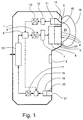
- eine schematische Darstellung eines Hörers mit einer Regelschaltung zum Steuern des Lautsprechers.
- Fig. 1
- is a schematic representation of a receiver with a control circuit for controlling the speaker.
In Fig. 1 ist andeutungsweise ein Handapparat 1 eines Telefons gezeigt. Dieser kann mit
Bedienungselementen z. B. mit einer optischen Anzeige 2 (Display), einer Tastatur (nicht
dargestellt) oder dergleichen ausgestattet sein (wie es zum Beispiel für Handys oder
Schnurlostelefone üblich ist). In einem als Hörmuschel 3 ausgebildeten Bereich des Gehäuses
ist eine Mehrzahl von Öffnungen 4 vorgesehen. Die Öffnungen 4 stellen den akustischen
Ausgang eines Raumvolumens 5 dar, in welchem ein Lautsprecher 6 (elektroakustischer
Wandler) eingebaut ist. Der Lautsprecher 6 wird in an sich bekannter Weise durch
einen Verstärker 7 angesteuert. Der Verstärker 7 wird mit analogen Sprachsignalen beaufschlagt,
welche von einem anderen Telefongerät auf digitalem Weg an die Telefonschaltung
10 des Handapparates 1 übertragen worden sind.In Fig. 1, a
Der Handapparat 1 hat auch ein Mikrofon 19 im Bereich der Sprechmuschel (welche am
unteren Ende der Frontseite des Handapparates 1 angeordnet ist). Das Mikrofon 19 nimmt
den vom Gerät zu übertragenden Schall auf, welcher durch eine Öffnung 21 des Gehäuses
und ein hinter der Öffnung 21 angeordnetes Raumvolumen 20 eintritt. Ein Verstärker 18
bereitet das Signal in an sich bekannter Weise auf, so dass es von einem A/D-Wandler 17
digitalisierten und an die Telefonschaltung 10 abgegeben werden kann (für die Übertragung
an ein nicht dargestelltes Gerät des Gesprächspartners).The
Im Rahmen der Erfindung werden die digitalen Signale am Ausgang der Telefonschaltung
10 zunächst durch einen digitalen Signalprozessor 9 (DSP) verarbeitet, bevor sie über den
D/A-Wandler 8 an den Verstärker 7 ausgegeben werden. Der DSP 9 hat einen zusätzlichen
Eingang für die von einem Mikrofon 11 aufgenommenen, von einem Verstärker 12 aufbereiteten
und von einem A/D-Wandler 13 digitalisierten Signale.In the context of the invention, the digital signals at the output of the
Das Mikrofon 11 befindet sich am hinteren Ende eines Raumvolumens 14. Am vorderen
Ende hat das genannte Raumvolumen 14 eine Öffnung 15, welche neben den Öffnungen 4
in der Hörmuschel 3 plaziert ist. Die beiden Raumvolumen 5 und 14 sind durch Zwischenwände
getrennt und akustisch entkoppelt.The
Bei der Benutzung des Handapparates 1 läuft folgendes ab: Die akustischen Signale des
Lautsprechers 6 werden durch die Öffnungen 4 an das Ohr 16 des Benutzers abgestrahlt. When using the
Im Zwischenraum 22, welcher zwischen der Hörmuschel 3 und dem Ohr 16 gebildet wird,
baut sich ein bestimmter Schallpegel auf. Dieser hängt davon ab, wie stark der genannte
Zwischenraum 22 aufgrund des Kontaktes zwischen dem Ohr 16 und der Hörmuschel 3
abgeschlossen ist. Bei einem engen Kontakt ist das akustische Leck relativ klein. Entsprechend
ist der vom Mikrofon 11 gemessene Schalldruck verhältnismässig hoch. Das elektrische
Signal des Mikrofons 11 wird durch den Verstärker 12 im erforderlichen Mass verstärkt
und über den A/D-Wandler 13 an den DSP 9 abgegeben. Ist dagegen an einer Stelle
ein Spalt 23 (akustisches Leck) zwischen Ohr 16 und Hörmuschel 3 (Ohrauflage) vorhanden,
baut sich im Zwischenraum 22 ein geringerer Schalldruck auf. Infolgedessen wird das
Messsignal im Verhältnis zur abgestrahlten akustischen Leistung des Lautsprechers 6 kleiner
sein.A certain sound level builds up in the
Der DSP 9 verwendet das vom Mikrofon 11 gelieferte Messsignal, um die Leistung des
Verstärkers 7 und damit des Lautsprechers 6 optimal einzustellen. Je größer das Verhältnis
"Messsignal zu abgestrahltem Signal", desto geringer die eingestellte Lautstärke. Umgekehrt
wird bei einer im Verhältnis zum abzustrahlenden Signal geringen Stärke des Messsignals
die Leistung des Verstärkers 7 hochgeschraubt, damit der Benutzer trotz des hohen
akustischen Lecks den Gesprächspartner verstehen kann.The
Es gibt verschiedene Möglichkeiten, das gemessene Signal zur Regelung zu verwenden. Es kann z. B. einfach die gesamte Leistung ermittelt werden. Es kann aber auch mit einem Filter ein bestimmter Spektralbereich herausgeholt werden und die Leistung in diesem Bereich als Regelgrösse verwendet werden. In diesem Sinn kann z. B. die untere Hälfte des Spektralbereichs des Signals extrahiert werden. Häufig werden nämlich die oberen Frequenzen ohnehin relativ gut übertragen und sind daher nicht kritisch.There are various ways of using the measured signal for control. It can e.g. B. simply determine the total power. But it can also be done with one Filters a certain spectral range and get the performance in that Area can be used as a control variable. In this sense, e.g. B. the lower half of the Spectral range of the signal can be extracted. The upper frequencies are often used transmitted relatively well anyway and are therefore not critical.
Die Art der Filterung kann auch davon abhängen, von welcher Art die Lautsprecherkapsel ist. Der Effekt des akustischen Lecks, nämlich dass tiefere Frequenzen schwächer erscheinen, ist bei piezo-elektrischen Lautsprecherkapseln deutlicher als bei magnetischen Kapseln. The type of filtering can also depend on the type of the speaker capsule is. The effect of the acoustic leak, namely that lower frequencies appear weaker, is clearer with piezo-electric speaker capsules than with magnetic ones Capsules.
Im DSP 9 kann z. B. ein PID-Regler implementiert sein. Es können aber auch prädiktive Steuerungen eingesetzt werden. Denkbar ist auch, dass eine Tabelle abgespeichert ist, aus welcher sich zu jedem Wert des Messsignals ein vorbestimmter Ausgabewert für den Verstärkungsfaktor ergibt. Es kann auch eine stufenförmige Schaltkurve realisiert werden. D. h. es wird zwischen zwei, drei oder mehr diskreten Sollwerten hin und her geschaltet.In DSP 9 z. B. a PID controller can be implemented. But it can also be predictive Controls are used. It is also conceivable that a table is saved from which corresponds to a predetermined output value for the gain factor for each value of the measurement signal results. A step-shaped switching curve can also be implemented. D. H. it is switched between two, three or more discrete setpoints.
Es empfiehlt sich, bei der Regelung der Lautstärke des Lautsprechers 6 das von der Telefonschaltung
10 abgegebene Nutzsignal zu berücksichtigen. Bei geringem akustischem
Leck wird das vom Mikrofon 11 aufgenommene Signal bis auf einige Verzerrungen (welche
durch die akustische Übertragung zwischen Lautsprecher 6 und Mikrofon 11 bedingt sind)
dem von der Telefonschaltung 10 gelieferten "Soll-Signal" entsprechen. Der DSP 9 wird in
diesem Fall dafür sorgen, dass das geringe akustische Leck kompensiert wird.It is recommended that the volume of the
Die Kompensation ist bei geringen Abständen von z. B. weniger als 1 cm gut möglich. Bei
einigen wenigen Zentimetern wird das akustische Leck schon schnell recht gross sein.
Wird der Hörer ganz vom Ohr entfernt, fällt der Schalldruck zusammen, was dank der
Rückführung über Mikrofon 11, Verstärker 12, A/D-Wandler 13 zum DSP 9 festgestellt
wird. In dieser Situation kann der DSP 9 auf den Freisprechbetrieb umschalten. In diesem
Zusammenhang kann auch das Signal des Mikrofons 19 der Sprechmuschel bei Bedarf
mehr verstärkt werden als üblich, um den vermutlich grösseren Abstand zwischen
Sprechmuschel des Handapparates 1 und Kopf des Benutzers zu kompensieren. Die
Steuerung des Verstärkers 18 kann vom DSP 9 aus erfolgen.The compensation is at short intervals of z. B. less than 1 cm possible. At
a few centimeters, the acoustic leak will quickly be quite large.
If the listener is completely removed from the ear, the sound pressure collapses, which thanks to the
Feedback via
Aus dem oben Gesagten ergibt sich, dass das akustische Leck im Prinzip nur dann festgestellt werden kann, wenn der Lautsprecher ein akustisches Signal abstrahlt. Sollen in längeren Pausen Messungen durchgeführt werden, können auch von Zeit zu Zeit Testsignale erzeugt und vom Lautsprecher abgegeben werden. Allerdings können solche Testsignale vom Benutzer als störend empfunden werden.From what has been said above, it follows that the acoustic leak is only found in principle if the loudspeaker emits an acoustic signal. Should be in longer Taking pause measurements can also test signals from time to time generated and emitted by the speaker. However, such test signals can are perceived by the user as annoying.
In kürzeren Signal-Pausen kann der zuletzt benutzte Verstärkungsfaktor beibehalten werden. Bei längeren Pausen kann es sinnvoll sein, den Verstärkungsfaktor auf einen bestimmten Wert überzuführen. The last used gain factor can be retained in shorter signal pauses. During longer breaks, it can be useful to set the gain factor to a specific one To transfer value.
Selbstverständlich beschränkt sich die Erfindung nicht auf das dargestellte Ausführungsbeispiel. Insbesondere kann die Steuerung auch mit analogen elektronischen Komponenten und damit analogen Signalen realisiert werden. Es ist auch möglich, die erfindungsgemässe elektronische Kompensation mit der aus dem Stand der Technik bekannten akustischen Rückkopplung des Verstärkers zu kombinieren. Die akustische Rückkopplung sorgt dann für eine optimale Effizienz der Abstrahlung zum Ohr hin. Der akustische Sensor ermöglicht eine Verbesserung insbesondere bei erhöhtem akustischen Leck.Of course, the invention is not limited to the illustrated embodiment. In particular, the control system can also use analog electronic components and thus analog signals can be realized. It is also possible to use the method according to the invention electronic compensation with the acoustic known from the prior art Combine feedback of the amplifier. The acoustic feedback ensures then for optimal radiation efficiency towards the ear. The acoustic sensor enables an improvement especially with increased acoustic leak.
In der Fig. 1 ist zwar das Raumvolumen 14 getrennt vom Raumvolumen 5 dargestellt. Es ist
aber auch möglich, das Raumvolumen 14 und den akustischen Sensor innerhalb (z. B. im
Zentrum) des Raumvolumens 5 anzuordnen. Ferner könnte eine Art "Meßkanal" hinter
einer der Öffnungen 4 angeschlossen werden, welcher den Schalldruck aus dem Bereich
des Raumvolumens 5 hinaus zum Mikrofon 11 führt.1, the
Stellt der DSP 9 fest, daß das akustische Leck zu groß ist, als daß das Gerät im normalen
Hörer-Modus sinnvoll betrieben werden kann, schaltet er auf eine hohe Leistung um, so
daß im Freisprech-Modus telefoniert werden kann. Es ist sogar denkbar, eine automatische
Umschaltung auf einen externen Lautsprecher vorzusehen. Zu diesem Zweck könnte
der DSP 9 noch einen Ausgang zur Telefonschaltung 10 haben. Stellt der DSP 9 fest, dass
das akustische Leck zu gross ist, signalisiert er dies der Telefonschaltung 10, welche ihrerseits
dann das Sprachsignal nicht mehr (bzw. nicht mehr nur) an den Lautsprecher 6 sondern
(zusätzlich) an einen (nicht dargestellten) leistungsfähigeren Lautsprecher (welcher z.
B. in der zugeordneten Tischstation oder auch direkt im Handapparat integriert sein kann,
oder welcher auch durch den über Kabel angeschlossenen Fahrzeuglautsprecher gebildet
sein kann).If the
Bei einem drahtgebundenen Handapparat wird die Telefonschaltung im Normalfall in der Tischstation eingebaut sein. Bei einem Handy sind andererseits zusätzliche HF-Schaltungen für den Empfang der Funksignale vorgesehen. Die Erfindung kann aber auch bei Kopfhörern oder dergleichen eingesetzt werden, um die Lautstärke und/oder das Signalspektrum auch bei nicht optimaler Plazierung des Kopfhörers automatisch richtig einstellen zu können.With a wired handset, the telephone circuit is normally in the Table station must be installed. On the other hand, with a cell phone there are additional RF circuits intended for the reception of radio signals. The invention can also be used with headphones or the like can be used to control the volume and / or the signal spectrum even if the headphones are not optimally positioned can.
Zusammenfassend ist festzustellen, dass durch die Erfindung die Möglichkeit geschaffen worden ist, die Lautstärke (bzw. das Spektrum) der Hörmuschel in Abhängigkeit von den jeweiligen Bedingungen richtig einzustellen.In summary, it should be noted that the invention creates the possibility has been the volume (or spectrum) of the earpiece depending on the to set the respective conditions correctly.
Claims (14)
Priority Applications (2)
| Application Number | Priority Date | Filing Date | Title |
|---|---|---|---|
| EP00810124A EP1126684A1 (en) | 2000-02-14 | 2000-02-14 | Method for controlling the sound volume of an electro-acoustic transducer |
| US09/775,635 US20010014161A1 (en) | 2000-02-14 | 2001-02-05 | Method for controlling a loudness level of an electroacoustic transducer |
Applications Claiming Priority (1)
| Application Number | Priority Date | Filing Date | Title |
|---|---|---|---|
| EP00810124A EP1126684A1 (en) | 2000-02-14 | 2000-02-14 | Method for controlling the sound volume of an electro-acoustic transducer |
Publications (1)
| Publication Number | Publication Date |
|---|---|
| EP1126684A1 true EP1126684A1 (en) | 2001-08-22 |
Family
ID=8174547
Family Applications (1)
| Application Number | Title | Priority Date | Filing Date |
|---|---|---|---|
| EP00810124A Withdrawn EP1126684A1 (en) | 2000-02-14 | 2000-02-14 | Method for controlling the sound volume of an electro-acoustic transducer |
Country Status (2)
| Country | Link |
|---|---|
| US (1) | US20010014161A1 (en) |
| EP (1) | EP1126684A1 (en) |
Families Citing this family (19)
| Publication number | Priority date | Publication date | Assignee | Title |
|---|---|---|---|---|
| FR2844405B1 (en) * | 2002-09-05 | 2004-12-03 | Cit Alcatel | STRUCTURAL ARRANGEMENT FOR A RADIO COMMUNICATION TERMINAL COMPRISING A SPEAKER AND AN EARPHONE |
| JP2004157295A (en) * | 2002-11-06 | 2004-06-03 | Oki Electric Ind Co Ltd | Audio reproduction device and method of correcting performance data |
| WO2004080116A2 (en) * | 2003-03-07 | 2004-09-16 | Sonion Horsens A/S | Speaker unit with active leak compensation |
| US7570769B2 (en) * | 2004-04-23 | 2009-08-04 | Motorola, Inc. | Air leak self-diagnosis for a communication device |
| EP1865745A4 (en) * | 2005-04-01 | 2011-03-30 | Panasonic Corp | Handset, electronic device, and communication device |
| US8155330B2 (en) * | 2009-03-31 | 2012-04-10 | Apple Inc. | Dynamic audio parameter adjustment using touch sensing |
| US9344051B2 (en) * | 2009-06-29 | 2016-05-17 | Nokia Technologies Oy | Apparatus, method and storage medium for performing adaptive audio equalization |
| WO2011110901A1 (en) * | 2010-03-12 | 2011-09-15 | Nokia Corporation | Apparatus, method and computer program for controlling an acoustic signal |
| CN103493508B (en) * | 2011-05-13 | 2017-02-15 | 索尼爱立信移动通讯有限公司 | Electronic devices for reducing acoustic leakage effects and related methods |
| CN102384821B (en) * | 2011-08-10 | 2015-07-29 | 歌尔声学股份有限公司 | Loudspeaker module air tightness testing method, test fixture and test macro |
| US9374448B2 (en) | 2012-05-27 | 2016-06-21 | Qualcomm Incorporated | Systems and methods for managing concurrent audio messages |
| EP2768208B1 (en) * | 2013-02-19 | 2018-09-19 | BlackBerry Limited | Methods and apparatus for improving audio quality using an acoustic leak compensation system in a mobile device |
| US9148725B2 (en) | 2013-02-19 | 2015-09-29 | Blackberry Limited | Methods and apparatus for improving audio quality using an acoustic leak compensation system in a mobile device |
| EP2863651A1 (en) | 2013-10-18 | 2015-04-22 | Nxp B.V. | Acoustic coupling sensor for mobile device |
| US20160035334A1 (en) * | 2014-02-14 | 2016-02-04 | Dennis McNutt | Audio system and method for reduction and/or elimination of distortion |
| WO2015152937A1 (en) * | 2014-04-04 | 2015-10-08 | Empire Technology Development Llc | Modifying sound output in personal communication device |
| US9626950B2 (en) * | 2015-02-13 | 2017-04-18 | Dennis McNutt | Audio system and method for reduction and/or elimination of distortion |
| CA2997828A1 (en) * | 2015-09-10 | 2017-03-16 | Yayuma Audio Sp. Z.O.O. | A method of an audio signal correction |
| US10957445B2 (en) | 2017-10-05 | 2021-03-23 | Hill-Rom Services, Inc. | Caregiver and staff information system |
Citations (5)
| Publication number | Priority date | Publication date | Assignee | Title |
|---|---|---|---|---|
| WO1984000274A1 (en) * | 1982-06-30 | 1984-01-19 | B & W Loudspeakers | Environment-adaptive loudspeaker systems |
| US5539831A (en) * | 1993-08-16 | 1996-07-23 | The University Of Mississippi | Active noise control stethoscope |
| WO1997003536A1 (en) * | 1995-07-07 | 1997-01-30 | University Of Salford | Loudspeaker circuit with means for monitoring the pressure at the speaker diaphragm, means for monitoring the velocity of the speaker diaphragm and a feedback circuit |
| US5600718A (en) * | 1995-02-24 | 1997-02-04 | Ericsson Inc. | Apparatus and method for adaptively precompensating for loudspeaker distortions |
| WO2000021331A1 (en) * | 1998-10-06 | 2000-04-13 | Bang & Olufsen A/S | Environment adaptable loudspeaker |
Family Cites Families (1)
| Publication number | Priority date | Publication date | Assignee | Title |
|---|---|---|---|---|
| US5966695A (en) * | 1995-10-17 | 1999-10-12 | Citibank, N.A. | Sales and marketing support system using a graphical query prospect database |
-
2000
- 2000-02-14 EP EP00810124A patent/EP1126684A1/en not_active Withdrawn
-
2001
- 2001-02-05 US US09/775,635 patent/US20010014161A1/en not_active Abandoned
Patent Citations (5)
| Publication number | Priority date | Publication date | Assignee | Title |
|---|---|---|---|---|
| WO1984000274A1 (en) * | 1982-06-30 | 1984-01-19 | B & W Loudspeakers | Environment-adaptive loudspeaker systems |
| US5539831A (en) * | 1993-08-16 | 1996-07-23 | The University Of Mississippi | Active noise control stethoscope |
| US5600718A (en) * | 1995-02-24 | 1997-02-04 | Ericsson Inc. | Apparatus and method for adaptively precompensating for loudspeaker distortions |
| WO1997003536A1 (en) * | 1995-07-07 | 1997-01-30 | University Of Salford | Loudspeaker circuit with means for monitoring the pressure at the speaker diaphragm, means for monitoring the velocity of the speaker diaphragm and a feedback circuit |
| WO2000021331A1 (en) * | 1998-10-06 | 2000-04-13 | Bang & Olufsen A/S | Environment adaptable loudspeaker |
Also Published As
| Publication number | Publication date |
|---|---|
| US20010014161A1 (en) | 2001-08-16 |
Similar Documents
| Publication | Publication Date | Title |
|---|---|---|
| EP1126684A1 (en) | Method for controlling the sound volume of an electro-acoustic transducer | |
| DE69531413T2 (en) | Transceiver with an acoustic transducer of the earpiece type | |
| DE69632896T2 (en) | Equalization of speech signals in a mobile phone | |
| EP1489885B1 (en) | Method for operating a hearing aid system as well as a hearing aid system with a microphone system in which different directional characteristics are selectable | |
| DE69834371T2 (en) | Mobile phone with speakerphone | |
| DE10331956B3 (en) | Hearing aid and method for operating a hearing aid with a microphone system, in which different Richtcharaktistiken are adjustable | |
| EP2172063B1 (en) | User-adaptable hearing aid comprising an initialization module | |
| DE3204567A1 (en) | HOERGERAET | |
| DE3512999A1 (en) | DIFFERENTIAL HEARING AID WITH PROGRAMMABLE FREQUENCY GEAR | |
| EP0219025B1 (en) | Hearing aid | |
| DE10146886A1 (en) | Hearing aid with automatic switching to hearing coil operation | |
| DE10359656A1 (en) | telecommunications equipment | |
| EP0989775A1 (en) | Hearing aid with signal quality monitoring device | |
| DE2826345C2 (en) | Phone adapter | |
| DE2336319A1 (en) | PROCEDURE FOR FEEDBACK STABILIZATION AND MINIATURE SOUND AMPLIFIER SYSTEM, IN PARTICULAR FOR HEAVY-DUTY DEVICES | |
| EP1920589A1 (en) | Apparatus for position-dependent control | |
| DE60317368T2 (en) | NONLINEAR ACOUSTIC ECHO COMPENSATOR | |
| DE602006000772T2 (en) | The hearing instrument | |
| EP1432282B1 (en) | Method for adapting a hearing aid to a momentary acoustic environment situation and hearing aid system | |
| DE19640412C1 (en) | Telecommunication terminal with two acoustic output frequency bands | |
| DE69908930T2 (en) | TELEPHONE WITH LOW-FREQUENCY ENHANCEMENT MEANS | |
| DE19600965C2 (en) | Mobile telephone device | |
| EP0452734B1 (en) | Hands free telephone device | |
| DE3616314A1 (en) | Telephone set with hands-free device | |
| EP3679729B1 (en) | Multi-purpose high performance hearing aid with a mobile end device in particular smartphone |
Legal Events
| Date | Code | Title | Description |
|---|---|---|---|
| PUAI | Public reference made under article 153(3) epc to a published international application that has entered the european phase |
Free format text: ORIGINAL CODE: 0009012 |
|
| AK | Designated contracting states |
Kind code of ref document: A1 Designated state(s): AT BE CH CY DE DK ES FI FR GB GR IE IT LI LU MC NL PT SE |
|
| AX | Request for extension of the european patent |
Free format text: AL;LT;LV;MK;RO;SI |
|
| 17P | Request for examination filed |
Effective date: 20011020 |
|
| RAP1 | Party data changed (applicant data changed or rights of an application transferred) |
Owner name: SWISSVOICE AG |
|
| AKX | Designation fees paid |
Free format text: AT BE CH CY DE DK ES FI FR GB GR IE IT LI LU MC NL PT SE |
|
| STAA | Information on the status of an ep patent application or granted ep patent |
Free format text: STATUS: THE APPLICATION IS DEEMED TO BE WITHDRAWN |
|
| 18D | Application deemed to be withdrawn |
Effective date: 20050830 |