EP1123843A2 - Vehicle's communication apparatus - Google Patents
Vehicle's communication apparatus Download PDFInfo
- Publication number
- EP1123843A2 EP1123843A2 EP20010102427 EP01102427A EP1123843A2 EP 1123843 A2 EP1123843 A2 EP 1123843A2 EP 20010102427 EP20010102427 EP 20010102427 EP 01102427 A EP01102427 A EP 01102427A EP 1123843 A2 EP1123843 A2 EP 1123843A2
- Authority
- EP
- European Patent Office
- Prior art keywords
- vehicle
- communication
- pseudo creature
- pseudo
- communication apparatus
- Prior art date
- Legal status (The legal status is an assumption and is not a legal conclusion. Google has not performed a legal analysis and makes no representation as to the accuracy of the status listed.)
- Ceased
Links
- 238000004891 communication Methods 0.000 title claims description 107
- 230000010365 information processing Effects 0.000 claims abstract description 16
- 230000004397 blinking Effects 0.000 claims description 10
- 238000012423 maintenance Methods 0.000 claims description 9
- 230000014509 gene expression Effects 0.000 claims description 7
- 210000000056 organ Anatomy 0.000 claims description 3
- 230000005540 biological transmission Effects 0.000 abstract description 11
- 238000010586 diagram Methods 0.000 description 22
- 230000004044 response Effects 0.000 description 17
- 230000006870 function Effects 0.000 description 14
- 238000006243 chemical reaction Methods 0.000 description 13
- 239000000446 fuel Substances 0.000 description 8
- 239000002828 fuel tank Substances 0.000 description 8
- 239000003921 oil Substances 0.000 description 8
- 238000007689 inspection Methods 0.000 description 6
- 210000003128 head Anatomy 0.000 description 5
- 239000010763 heavy fuel oil Substances 0.000 description 5
- 230000006399 behavior Effects 0.000 description 3
- 238000005286 illumination Methods 0.000 description 3
- 208000004350 Strabismus Diseases 0.000 description 2
- 230000009471 action Effects 0.000 description 2
- 230000008859 change Effects 0.000 description 2
- 239000000498 cooling water Substances 0.000 description 2
- 238000001514 detection method Methods 0.000 description 2
- 239000004973 liquid crystal related substance Substances 0.000 description 2
- 238000000034 method Methods 0.000 description 2
- 238000012545 processing Methods 0.000 description 2
- 229920003002 synthetic resin Polymers 0.000 description 2
- 239000000057 synthetic resin Substances 0.000 description 2
- 229910000838 Al alloy Inorganic materials 0.000 description 1
- 241001465754 Metazoa Species 0.000 description 1
- 241000283973 Oryctolagus cuniculus Species 0.000 description 1
- 206010041349 Somnolence Diseases 0.000 description 1
- 238000005266 casting Methods 0.000 description 1
- 230000006835 compression Effects 0.000 description 1
- 238000007906 compression Methods 0.000 description 1
- 230000007423 decrease Effects 0.000 description 1
- 238000003745 diagnosis Methods 0.000 description 1
- 238000007599 discharging Methods 0.000 description 1
- 239000003502 gasoline Substances 0.000 description 1
- 239000000463 material Substances 0.000 description 1
- 238000005259 measurement Methods 0.000 description 1
- 229910052751 metal Inorganic materials 0.000 description 1
- 239000002184 metal Substances 0.000 description 1
- 230000008569 process Effects 0.000 description 1
- 239000000126 substance Substances 0.000 description 1
- 235000019640 taste Nutrition 0.000 description 1
- 230000002618 waking effect Effects 0.000 description 1
Images


Classifications
-
- G06Q50/40—
-
- B—PERFORMING OPERATIONS; TRANSPORTING
- B60—VEHICLES IN GENERAL
- B60R—VEHICLES, VEHICLE FITTINGS, OR VEHICLE PARTS, NOT OTHERWISE PROVIDED FOR
- B60R16/00—Electric or fluid circuits specially adapted for vehicles and not otherwise provided for; Arrangement of elements of electric or fluid circuits specially adapted for vehicles and not otherwise provided for
- B60R16/02—Electric or fluid circuits specially adapted for vehicles and not otherwise provided for; Arrangement of elements of electric or fluid circuits specially adapted for vehicles and not otherwise provided for electric constitutive elements
- B60R16/023—Electric or fluid circuits specially adapted for vehicles and not otherwise provided for; Arrangement of elements of electric or fluid circuits specially adapted for vehicles and not otherwise provided for electric constitutive elements for transmission of signals between vehicle parts or subsystems
- B60R16/0231—Circuits relating to the driving or the functioning of the vehicle
- B60R16/0232—Circuits relating to the driving or the functioning of the vehicle for measuring vehicle parameters and indicating critical, abnormal or dangerous conditions
Definitions
- the present invention generally relates to a communication apparatus for a vehicle. More particularly, the present invention relates to a vehicle's communication apparatus capable of further deepening the feeling of intimacy of the driver and / or the owner of the vehicle with the vehicle, and the affection of the driver and / or the owner of the vehicle for the vehicle. It should be noted that the driver and / or the owner are regarded as a generic group referred to hereafter as the user.
- expression of a pseudo creature is expected to allow the user to recognize information such as the condition of the vehicle as information of intimacy. Since displayed pseudo creatures are limited to only those set in the vehicle in advance, however, the expression of the pseudo creatures cannot be said to be necessarily sufficient for satisfying the user's strong desire for a variety of hobbies. In addition, since the user is capable of communicating with such pseudo creatures only while the user is present inside the car, it is feared that the user's affection for the car unavoidably weakens.
- the pseudo creature communicates with the driver only through a picture and a sound.
- the conventional communication apparatus is not a sufficiently complete apparatus.
- a motor-bicycle does not have a cabin.
- introduction of light and sound generated by external sources to the driver of a motor-bicycle is not restricted.
- communication is difficult to establish merely by using pictures and sounds only.
- the pseudo creature communicates only with the driver but not with other users of the vehicle.
- the present invention provides a vehicle communication apparatus allowing a pseudo creature set in the vehicle to communicate with a communication partner outside the vehicle through a function of the vehicle.
- the communication apparatus has the following characteristics.
- the pseudo creature is introduced from electronic media outside the vehicle through a communication means mounted on the vehicle.
- the electronic media is a media connected to the Internet.
- the electronic media is a personal computer or a computer game machine and the pseudo creature is a character making its appearance in a game.
- the pseudo creature can be changed to a variety of forms selectable as one, which the pseudo character is to be set at.
- the second characteristic it is possible to acquire data required for setting a pseudo creature from the Internet whereas, in accordance with the third characteristic, the user is allowed to select a character the user likes from a game, and adopt the character in the vehicle.
- the present invention also has a data-transmitting means for transmitting running data of the vehicle to the electronic media by way of the communication means.
- the running data transmitted by the data-transmitting means is used in the operation of the electronic media, making it possible to typically enhance the function of the electronic media.
- the present invention has a communication means capable of communicating with an electronic information-processing apparatus outside the vehicle.
- Representative examples of the electronic information-processing apparatus are a telephone, a fax machine and a personal computer.
- the electronic information-processing apparatus is a personal computer set as a means used in an organ doing maintenance of the vehicle.
- the electronic information-processing apparatus processes information received from the vehicle so as to raise the value of the utilization of the vehicle.
- the maintenance organ such as a vehicle dealer is capable of providing data such as information on vehicle maintenance based on information received from the vehicle.
- the present invention provides a vehicle communication apparatus wherein a pseudo creature set on the vehicle is capable of communicating with a communication partner outside the vehicle through a function of the vehicle.
- a functional component of the vehicle known as an auxiliary instrument is provided to function as a communication means of the pseudo creature, and in order for the auxiliary instrument to represent an intention and a feeling of the pseudo creature, the auxiliary instrument is driven by a state of expression set in advance.
- the apparatus is characterized in that the auxiliary instrument functioning as a communication means is at least either a light device or a warning device.
- a light device provided on a front portion of the vehicle to serve as an auxiliary instrument is blinking when expressing a movement of an eye of the pseudo creature.
- a light device provided on a rear portion of the vehicle to serve as an auxiliary instrument is blinking when expressing a movement of a tail of the pseudo creature.
- a warning device serving as an auxiliary instrument is activated when expressing a cry of the pseudo creature.
- an intention and a feeling of the pseudo creature that is, the state of the vehicle, or a response to an access made by an external accessor are expressed in the external accessor by a functional component provided on the vehicle in advance.
- the driver is capable of easily recognizing information expressed by the pseudo creature.
- the light devices can be activated to generate pseudo movements of the eyes and the tail of the pseudo creature whereas the warning device can be actuated to produce a pseudo cry of the pseudo creature.
- a vehicle communication apparatus that has a pseudo creature set in the vehicle and capable of communicating with a communication partner outside the vehicle through a function of the vehicle and, as a twelfth characteristic of the present invention, the pseudo creature has a communication means for communicating with a pseudo creature set in another vehicle.
- the vehicle communication apparatus provided by the present invention further has a recognition means for recognizing a position of a pseudo creature set in another vehicle and a display means for displaying the recognized position of the pseudo creature set in the other vehicle.
- the vehicle communication apparatus provided by the present invention further has a notification means for informing a pseudo creature set in another vehicle of its own state.
- the user is capable of communicating with not only a pseudo creature set in its own vehicle but also a pseudo creature set in another vehicle.
- the user is capable of knowing the position of a pseudo creature set in another vehicle and, in accordance with the fourteenth characteristic, the user is capable of informing a user riding another vehicle of its own state.
- an electronic information-processing apparatus such as a phone, a fax machine or a PC
- a maintenance institution such as a vehicle dealer is capable of providing data such as maintenance information based on information received from the vehicle.
- a pseudo creature input by a maintenance institution can be set on the vehicle.
- functional components provided in the vehicle in advance can be used for expressing an intention and a feeling of the pseudo creature.
- the user is capable of recognizing the expressed information with a high degree of reliability.
- a light and a sound generated by the light devices and the warning device respectively can be distinguished from lights and sounds generated by external sources with ease.
- the light devices and the warning device are appropriate communication means mounted on the motor-bicycle.
- behaviors of the pseudo creature are represented by the light devices and the warning device, it is possible to impress the driver that the entire vehicle and the pseudo creature are one and, hence, to further deepen the intimacy of the driver with the vehicle.
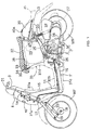
- Fig. 1 is a diagram showing a cross section of main components composing a motor-bicycle employing a vehicle communication apparatus provided by the present invention.
- the motor-bicycle is a scooter vehicle with a vehicle-body frame F comprising a front frame 11, a rear frame 12 and a sub-frame 13.
- the front frame 11 is made by adoption of a casting technique with typically an aluminum alloy used as a material.
- the rear frame 12 is joined to the rear end of the front frame 11.
- the sub-frame 13 is joined to the rear end of the rear frame 12.
- the front frame 11 comprises a head pipe 14, a down frame 15 and a pair of right and left floor support frames 16, which are assembled to form an integrated body.
- the down frame 15 is extended in the downward and backward directions from the head pipe 14.
- the floor support frames 16 are extended in the backward direction from the down frame 15.
- the head pipe 14 supports a front fork 17 in such a way that the front fork 17 can be rotated with a high degree of freedom.
- Two arms of the front fork 17 sandwich a front wheel WF.
- the lower edges of the arms of the front fork 17 are positioned in front of a wheel shaft 18 of the front wheel WF.
- the lower edges of the arms of the front fork 17 are joined to the right and left ends of the wheel shaft 18 respectively by links 19.
- a front cushion 20 is provided to join the middle of the link 19 to the vertical middle of the front fork 17.
- a handle 21 is fixed on the upper end of the front fork 17.
- a power unit P is supported at the longitudinal middle of the rear frame 12 by an anti-vibration link 22 in such a way that the power unit P can be swung.
- the power unit P comprises an engine E located in front of a rear wheel WR and a continuously variable transmission M located on the left side of the rear wheel WR.
- the engine E is typically a water-cooled single-cylinder 4-cycle engine with typically a cylinder thereof oriented all but horizontally toward the front of the vehicle body.
- the continuously variable transmission M is typically a belt transmission.
- the rear wheel WR is supported by a shaft on a rear portion of the power unit P.
- a rear cushion unit 23 is provided between the rear portion of the power unit P and the rear frame 12.
- an air cleaner 24 is attached above the rear wheel WR.
- the air cleaner 24 is connected to the engine E by a carburetor 25.
- an exhaust pipe 26 is extended from the engine E to the right side of the rear wheel WR.
- the exhaust pipe 26 is connected to an exhaust muffler 27 provided on the right side of the rear wheel WR.
- the engine E also supports a stand 28 in such a way that the stand 28 can be rotated with a high degree of freedom.
- a storage box 29 made of a synthetic resin is provided on the upper surface of the rear frame 12 forming the rear portion of the vehicle-body frame F, being held firmly at a position above the engine E and the carburetor 25.
- a fuel tank 30 having a cap 40a for injecting fuel to the fuel tank 30 is supported on the sub-frame 13.
- the vehicle-body frame F is veiled by a car-body cover 31 made of a synthetic resin.
- the car-body cover 31 comprises a leg shield 31a, a step floor 31b, an under cover 31c and a side cover 31d.
- the leg shield 31a covers a portion in front of the legs of the driver.
- the lower portion of the leg shield 31a is joined to the step floor 31b on which the feet of the driver are put.
- the under cover 31c covers the bottom of the step floor 31b.
- the side cover 31d veils surfaces on both sides of the rear portion of the vehicle body.
- a front shield 31e is attached to the front portion of the leg shield 31a.
- a meter unit 9 is provided over the leg shield 31a and the front shield 31e.
- a horn 10 is provided inside the front shield 31e, and a head light 8 is provided over the horn 10.
- a tail light unit 43 is provided on the rearmost tail of the car body of the side cover 31a.
- the tail light unit 43 includes a tail light provided at the transversal middle of the tail of the vehicle body, and rear winkers provided on the right and left sides.
- the fuel tank 30 and most of the storage box 29 supported on the rear frame 12 are veiled by the side cover 31d.
- a seat 32 for covering the upper surface of the storage box 29 is attached over the side cover 31d in such a way that the seat 32 can close or cover the storage box 29.
- the cap 40a for injecting fuel is provided in such a way that the cap 40a protrudes out off the upper portion of the side cover 31d.
- a bracket 33 is provided over the front edge of the storage box 29 in such a way that the bracket 33 protrudes in the forward direction.
- the bracket 33 supports a hinge plate 34 secured on the front edge of the seat 32 through a hinge pin 35 in such a way that the hinge plate 34 can be rotated around the bracket 33.
- the seat 32 is supported at the front edge of the storage box 29 in such a way that the seat 32 can be rotated in the upward and downward directions to respectively open and close the storage box 29.
- a seal rubber 36 is stuck on the bottom of the seat 32, being brought into contact with the entire circumference of the upper-end opening edge of the storage box 29. With the storage box 29 closed by the seat 32, the seal rubber 36 plays the role of a seal between the seat 32 and the storage box 29.
- the seal rubber 36 also applies an elastic force to the seat 32 in the upward direction.
- the seat 32 is supported in such a way that, with the storage box 29 closed by the seat 32, the seat 32 can be moved up and down in a range with the low limit determined by the upward force against compression of the seal rubber 36, and the seat 32 can respectively open and close the storage box 29.
- the state of the seat 32 to close or open the storage box 29 is detected by a seat switch not shown in the figure.
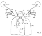
- Fig. 2 is a diagram showing a front view of some main components of the motor-bicycle
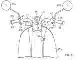
- Fig. 3 is a diagram showing a squint view of some main components of the motor-bicycle, which are seen from a position behind the leg shield 31a.
- front winkers 37L and 37R are provided on the meter unit 9, each being oriented in the outward direction.
- a power-supply switch 38 On the leg shield 31a on the right side of the vehicle body, there is provided a power-supply switch 38, which can be operated by using a power-supply key.
- a right-side grip 21R on the handle 21 is used for adjusting a throttle.
- a front-wheel brake lever 39 and a rear-wheel brake lever 40 are provided on the right-side grip 21R and a left-side grip 21L respectively.
- a brake switch is provided on the attachment root of each of the brake levers 39 and 40, that is, at a location in close proximity to a rotation axis of each of the brake levers 39 and 40.
- a brake switch is provided for detecting the operation of the respective brake.
- On the left-side handle 21 a headlight switch 41 and a horn switch 44 are provided.
- a winker switch 42 and a start switch 45 are provided on the right-side handle 21, on the other hand.
- the meter unit 9 comprises a meter 91 and a communication display unit 92.
- the meter unit 9 will be described in more detail by referring to Fig. 4.
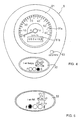
- Fig. 4 is a diagram showing an enlarged front view of the meter unit 9.
- the meter 91 and the communication display unit 92 described above are provided on the surface of the meter unit 9, the meter 91 and the communication display unit 92 described above are provided.
- a display-switching button 93 for switching the display from an odometer to a trip meter and vice versa.
- the meter 91 comprises a speed meter 91a for displaying the speed of the vehicle and a distance meter 91b, which can serve as the odometer or the trip meter in accordance with the operation carried out on the display-switching button 93.
- the displayed speed of the vehicle is a result of electrical detection.
- the operation carried out by the distance meter 91b can be digitally displayed on the liquid-crystal display device.
- An operation of a short duration carried out on the display-switching button 93 switches the distance meter 91b from the odometer to the trip meter or vice versa.
- an operation of a first long duration of typically 1 second carried out on the display-switching button 93 resets the trip meter.
- an operation of a second long duration of typically 3 seconds displays the state of the vehicle.
- the communication display unit 92 is a liquid-crystal display device for displaying the state of the vehicle and a result of communication with typically another vehicle. Furthermore, the meter unit 9 can also be provided with a microphone and a speaker system capable of generating a sound. It should be noted that neither the microphone nor the speaker system is shown in the figure.
- the state of the vehicle or the like can not only be displayed on the communication display unit 92, but can also be expressed by auxiliary instruments provided on the vehicle.
- the auxiliary instruments are functional components such as the head light 8, the horn 10, the front winkers 37L and 37R, the tail light unit 43 and the speaker system. That is to say, in this embodiment, the whole vehicle is assumed to be a pseudo creature.
- the vehicle assumed to be a pseudo creature has a configuration to make the user aware of information such as the state of the vehicle and data obtained as a result of communication between the vehicle and another electronic information-processing apparatus by driving the vehicle's display functions including the auxiliary instruments.
- the amount of residual fuel- is displayed as the character F representing a full fuel tank, the character E representing an empty fuel tank and one of circular indicators between the characters F and E.
- a character representing the pseudo creature is displayed along with a feeling-expressing phrase stating: "I am hungry.”
- the character representing the pseudo creature is a picture of a rabbit.
- Fig. 5 is a diagram showing another typical character representing the pseudo creature. As shown in Fig. 5, the state of the residual fuel in the fuel tank is displayed on the communication display unit 92 as a circular indicator representing a state close to a full fuel tank along with a phrase stating: "I am full" to indicate that fuel has been replenished.
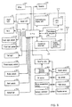
- Fig. 6 is a block diagram showing the configuration of the meter unit 9 and components connected to the meter unit 9 and mounted on the vehicle.
- the meter unit 9 includes a meter display CPU 50.
- the power-supply switch 38, a brake switch 51, a seat switch 52, a microphone 54, an immobilize system 55 and the display-switching button 93 are connected to the input side of the CPU 50.
- the head light 8, the horn 10, the front' winkers 37L and 37R, the tail light unit 43 and the speaker system 53 as well as the meter unit 91 and the communication display unit 92 are connected to the output side of the CPU 50.
- the CPU 50 includes a clock unit having a calendar function.
- the CPU 50 also includes a GPS unit 62, a transmission & reception unit 63 and a connection interface 65.
- the GPS unit 62 detects information on the position of the vehicle.
- the transmission & reception unit 63 is capable of transmitting and receiving information to and from another electronic information-processing apparatus.
- the connection interface 65 serves as an interface with external components.
- Running data is supplied to the CPU 50.
- the running data includes a distance measured by a running-distance measurement unit 64 and pieces of information on the state of the vehicle, which are detected by instruments such as a speed sensor 56, an engine rotation sensor (Ne sensor) 57, a residual-fuel-amount sensor (fuel sensor) 58, an oil-amount sensor (oil sensor) 59, a throttle sensor 60, an engine-cooling-water-temperature sensor (water-temperature sensor) 61 and a battery-voltage meter 74.
- instruments such as a speed sensor 56, an engine rotation sensor (Ne sensor) 57, a residual-fuel-amount sensor (fuel sensor) 58, an oil-amount sensor (oil sensor) 59, a throttle sensor 60, an engine-cooling-water-temperature sensor (water-temperature sensor) 61 and a battery-voltage meter 74.
- Fig. 7 is a block diagram showing electronic information-processing apparatuses connected to the CPU 50.
- the transmission & reception unit 63 is capable of transmitting and receiving information to and from a personal computer 66 referred to hereafter simply as a PC, a hand phone 67 and a fax machine 68 including a telephone through a public communication line.
- the transmission & reception unit 63 also has a function for transmitting and receiving information to and from a meter unit mounted on another vehicle 69 through radio communication, and a function for receiving a command to turn on a power supply from a remote controller 70 capable of transmitting a radio signal.
- the connection interface 65 is connected to apparatuses such as a PC 71, a hand phone 72 connectable to the Internet and a computer game machine 73.
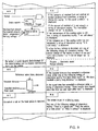
- Figs. 8 to 10 show operations carried out by the user and states of the vehicle whereas the right column shows commands issued by the CPU 50 to the communication display unit 92 and the auxiliary instruments in response to, among other things, the operations on the left column, which are carried out by the user.
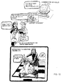
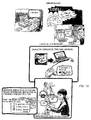
- Figs. 11 to 13 are each an illustration diagram for helping the reader visually better understand operations carried out in response to commands shown in Figs. 8 to 10. To begin with, before getting on the vehicle, the user carries out an operation denoted by a symbol Ml shown in Fig. 8.
- the user turns on a remote control switch 70 when the seat switch 52 is in an off state.
- a blinking command is issued to the front winkers 37L and 37R as well as the tail light 43
- a start command is issued to the engine and a forcing command to the horn 10.
- the front winkers 37L and 37R as well as the tail light 43 including the rear winkers are each put in a blinking state, the engine is started and the horn 10 is forcibly turned on for a predetermined period of time, which is typically 0.5 seconds.
- the operations of these auxiliary instruments are expressed by behaviors or states of the pseudo creature.
- the blinking state of the winkers and the tail light is expressed by winks or tail movements of the pseudo creature.
- the start of the engine is expressed by waking of the pseudo creature and a sound generated by the horn 10 is expressed by a cry of the pseudo creature.
- the operations are carried out by the auxiliary instruments before the user gets on the vehicle in order to provide enjoyment to the eyes of the user and convenience to the user in finding out the vehicle in a short period of time at, for example, a dark place or in a parking area where a number of motor-bicycles are parked.
- the operations of these auxiliary instruments may be terminated in a predetermined period of time such as 5 seconds, or terminated in response to a next operation M2.
- the user may also call out to the auxiliary instruments by outputting a voice command.
- the voice command issued by the user is recognized by typically comparing the command with a voice waveform cataloged in advance.
- the operation M2 is the behavior of the user to sit on the seat 32 or an operation to turn the seat switch 52 on, and an operation to turn on the power-supply switch 38.
- a greeting message from the vehicle is displayed on the communication display unit 92 and a pseudo sound such as "wing” or "piropiro” is generated electronically from the speaker 53 in response to the operations to turn on the seat switch and the power-supply switch 38.
- a physical-condition message is displayed on the communication display unit 92 to inform the user of the condition of the vehicle.
- Examples of the greeting message are “Good morning”, “I haven't seen you for a long time” and “A happy birthday”. Determination to display the "Good morning” greeting message is based on information on time obtained from the clock unit of the CPU 50. In dependence on the information on time, a “Good afternoon” or “Good evening” greeting message may be displayed instead of the "Good morning” message.
- the "I haven't seen you for a long time” greeting message is displayed when a time longer than a predetermined period has lapsed since the last operation to turn off the power-supply key.
- the "A happy birthday” greeting message is displayed on the user's birthday, which is typically stored in advance in a memory of the CPU 50.
- the calendar function compares each day with the stored birthday and, when a day matches the stored birthday, the "A happy birthday" greeting message is displayed.
- Examples of the physical-condition message are "I am extremely well” and “Today, let's go to a far place”. Determination to display a physical-condition message is based on information on the amount of residual fuel obtained from the fuel sensor 58 and information on the amount of residual oil obtained from the oil sensor 59.
- An operation M3 is an operation to temporarily halt the vehicle in the course of running.
- a message saying: "We have been traveling a long distance.” is displayed on the communication display unit 92 after a period of 2 seconds has lapsed since the vehicle was halted or the speed of the vehicle reached a zero at an intersection on a red traffic light for example. Determination to display the "We have been traveling a long distance.” character string is based on a travel distance.
- a message saying: "The lucky color of today is ---.” is displayed on the communication display unit 92. Determination to display the "The lucky color of today is - - -.” character string is based on information on a color stored in advance along with the birthday of the user.
- an access to a weather forecast service office is made through a public communication line to acquire a weather forecast, and a typical "It may rain.” message obtained as a result of the access is displayed.
- the weather forecast service office it is desirable to set the weather forecast service office to provide the vehicle with information on a weather forecast in the form of typically an identification code recognizable by the meter unit in response to a predetermined signal transmitted by the vehicle to make a request for the information on a weather forecast.
- the CPU 50 is capable of recognizing the identification code representing the information on a weather forecast and, hence, capable of selecting a weather-forecast message to be displayed.
- a weather-forecast message based on data such as calendar information, information on time and information on brightness.
- the information on brightness is based on a voltage output by a photoelectric conversion device provided typically on the surface of the meter unit 9.
- a symbol M4 represents a state in which the amount of residual fuel is smaller than a predetermined value.
- a string of characters urging the user to replenish fuel is displayed on the communication display unit 92. Examples of such a character string are "I am hungry.” and “Let's go to a gasoline station.”. If the lack of fuel remains as before even after a predetermined time has lapsed or a predetermined distance has been traveled since the issuance of the message urging the user to replenish fuel, a typical string of characters saying: "I can no longer run.” is displayed or a "piropiro" sound is generated electronically. In place of such a character string or along with the string of characters, illumination of the screen of the communication display unit 92 is changed to give the user a warning.
- An operation M5 is carried out to recognize the condition of the vehicle.
- An example of the operation M5 is an operation carried out by the user to grip and release the two brake levers 39 and 40 twice. This example is analogous to a double click of the computer operation. In this case, an operation to turn the brake switch 51 on and off is carried out twice within a predetermined period of time.
- a string of characters saying: "A very good condition.” is displayed on the communication display unit 92 to indicate that the amount of residual fuel and the amount of residual oil each exceed a predetermined quantity, or a string of characters saying: "I am still sleepy.” is displayed on the communication display unit 92 to indicate that the temperature of the cooling water has not increased to a predetermined value.
- a string of characters saying: "It is cold today.” is displayed on the communication display unit 92 to indicate that the temperature of the cooling water is still low in spite of the fact that a predetermined time has lapsed since an operation to start the engine.
- the operation M5 can be carried out as a substitute for an operation carried out on the display-switching button 93.
- a string of characters saying: "You had better change the oil.” is displayed on the communication display unit 92. If a low battery voltage is detected in the operation M5, a string of characters saying: "The electric charge of the battery is about to run out.” is displayed on the communication display unit 92. If an idle cell motor is detected in the operation M5, a string of characters saying: "Let's us see a doctor.” is displayed on the communication display unit 92.
- a symbol M6 denotes a state in which a predetermined distance has been traveled or a predetermined time has lapsed since the user got onto the vehicle for the first time.
- a reaction R6 to a state in which a predetermined distance has been traveled a string of characters saying: "You have done much.” or "We have traveled a pretty long distance.” is displayed on the communication display unit 92.
- a reaction R6 to a state in which a predetermined time has lapsed a string of characters saying; "Three months have lapsed since the time we saw each other last.” is displayed on the communication display unit 92.
- a symbol M7 denotes a state in which an incoming call arrives at the hand phone carried by the user.
- illumination of the screen of the communication display unit 92 is changed and a string of characters saying: "There is a phone call.” “Halt the vehicle at a safe place.” or "Who is calling?" is displayed on the communication display unit 92.
- a memory area for storing identification information corresponding to the number of the hand phone owned by the user and an identification-information-determining means for detecting the arrival of a call matching the identification information.
- a symbol M8 denotes a state in which the immobilize system 55 is operating.
- the immobilize system 55 is forced to operate without operating a regular key when the vehicle is moved.
- the horn 10 is driven and at least one of the lights is put in a blinking state to represent a reaction taken by the pseudo creature.
- a call to a phone number cataloged in advance is made.
- a fax machine or a PC cataloged in advance is activated to be informed of the vehicle's present position based on information on a position generated by the GPS unit 62.
- the map of an area in which the vehicle is located can also be transmitted to the fax machine or the PC.
- An operation M9 is an operation carried out to catalog personal information on the user such as the birthday and the name of the user. That is to say, the operation M9 is carried out so as to store basic data used for displaying the string of characters saying: "The lucky color of today is ---.” in response to the operation M3 or "Three months have lapsed since the time we saw each other last.” in response to the state M6.
- An operation M10 is an operation carried out by the vehicle when the vehicle meets another vehicle having a meter unit of the same type.
- a friend's scooter set in advance arrives at a location within a predetermined distance, approaching the vehicle, the vehicle carries out this operation M10.
- the scooter of the friend has a meter unit with a set pseudo creature of the same type as the vehicle.
- a calling signal is transmitted to the scooter.
- a signal received from the partner in response to the calling signal indicates that the approaching partner is located at a near location.
- a communication with a meter unit 9 mounted on the scooter of the friend can also be established typically to notify the friend of the user's own status such as the fact that the user is approaching the friend.
- a string of characters saying typically: "Hello, K.” can also be transmitted through the microphone 54 to the meter unit 9 mounted on the scooter of the friend.
- voice information is a message saying: "I will see you at the AA convenient store..”
- An operation M11 is an operation to connect the vehicle to the game machine 73.
- the pseudo creature representing the vehicle is allowed to participate in a game.
- the game machine 73 has been designed into a configuration in which characters appearing on the stage can be changed or the number of such characters can be increased.
- the meter unit 9 to the game machine 73 and by cataloging the name of the pseudo creature representing the vehicle in the game machine 73 as the name of a character participating in the game, it is possible to let the pseudo creature representing the vehicle join the game as a game-participant character of the game machine 73. In this case, the progress of the game can be changed by using traveling data of the vehicle.
- the power of the character rises or a hidden character is let appear on the stage in accordance with an increase in traveled distance.
- the power of a character increases or decreases in accordance with a variation in residual-fuel amount or a change in residual-oil amount.
- the game machine 73 is used while the vehicle is being parked so that, by allowing the pseudo creature representing the vehicle to participate in a game, the user can enjoy the game.
- the user can enjoy the game having abundant variable substances such as changes in character power with the traveled distance in the course of the game.
- An operation M12 is an operation to connect the vehicle to the PC 71.
- game software is loaded onto the PC 71, which is provided with a function to transmit data for displaying a character appearing in a game to the meter unit 9.
- the CPU 50 is capable of communicating with the PC 71, receiving the data for displaying a character of the game software and storing the data in a memory.
- the received data is processed by adoption of a predetermined algorithm matching the condition of the vehicle.
- the function to download game software can also be provided in the game machine 73.
- the operation M12 is carried out to connect the vehicle to the game machine 73.
- a character representing a pseudo creature is not limited to those read out from game software. Instead, it is also possible to use a character created by using the PC 71. In a word, any character can be used for representing the pseudo creature as long as data related to the character is acquired from an external electronic information-processing apparatus connected to the meter unit employed in the vehicle directly or through the Internet.
- the PC 71 includes software for diagnosing the operation of a vehicle based on the running data of the vehicle, it is also possible to determine the operating condition of the vehicle on the basis of running data supplied by the CPU 50. A result of the diagnosis can then be displayed on the communication display unit 92.
- the CPU 50 is capable of transmitting running data along with the identification information of the vehicle to a PC 71
- the dealer is capable of informing the vehicle of a periodical inspection through a public communication line, for example, when it is time to carry out a periodical inspection on the vehicle. If the motor-bicycle dealer transmits picture information as a notice of a periodical inspection to the vehicle, information on an inspection facility can be included in the notice and displayed as a picture on the communication display unit 92. The information on an inspection facility can be reported to the user by using a message of the pseudo creature received by the motor-bicycle dealer.
- the user pays more attention to the information on an inspection facility and can recognize the necessity of maintenance with ease.
- the user can have the vehicle receive a maintenance service with good timing and have more trust in the motor-bicycle dealer.
- the user is allowed to enjoy more visible variations in comparison with a message expressed by a monotonous string of characters.
- An operation M13 is an operation to connect the vehicle to the hand phone 72 having a function to connect itself to the Internet.
- R13 of this connection operation M13 it is possible to display information such as fortune-telling information and information on a weather forecast, which are acquired by the hand phone 72 through the Internet, on the communication display unit 92.
- a figure can be added to each of the character strings displayed in response to the operations and the states shown in Figs. 8 to 10.
- a response can be displayed as a figure only.
- the invention refers how to set a pseudo creature to be expressed in a vehicle as desired by the user, to increase the user's feeling that the pseudo creature expressed in the vehicle and the vehicle are one, to allow information generated by the pseudo creature to be recognized with ease and to allow the user to communicate with a plurality of other users through the pseudo creature.
- a CPU 50 employed in a meter unit 9 is capable of communicating with external apparatuses such as a PC, a hand phone and a game machine through a connection interface 65 and a transmission & reception unit 63.
- the meter CPU 50 is capable of transmitting information on the vehicle to an external apparatus such a PC and acquiring a character of a game or the like as a pseudo creature from electronic media or an electronic information-processing apparatus such as a PC.
- auxiliary instruments which are functional components of the vehicle such as a head light, winkers and a horn.
- the head light or the winkers provided on the front portion of the vehicle are put in a blinking state for expressing winks of the pseudo creature.
- a tail light or the winkers provided on the rear portion of the vehicle are put in a blinking state to express movements of the tail of the pseudo creature.
- a horn 10 is activated to express a cry of the pseudo creature.
- the CPU 50 is capable of transmitting information on the position of the vehicle, its own state and others to a pseudo creature set in another vehicle by way of a GPS unit 62 or the transmission & reception unit 63.
- a meter unit 9 provided on a vehicle receiving the transmitted information displays the information as a picture or a string of characters.
- a voice input via a microphone 54 can also be transmitted to another vehicle by way of the transmission & reception unit 63 to be reproduced by a speaker system 53 provided on the other vehicle.
Abstract
Description
- The present invention generally relates to a communication apparatus for a vehicle. More particularly, the present invention relates to a vehicle's communication apparatus capable of further deepening the feeling of intimacy of the driver and / or the owner of the vehicle with the vehicle, and the affection of the driver and / or the owner of the vehicle for the vehicle. It should be noted that the driver and / or the owner are regarded as a generic group referred to hereafter as the user.
- As disclosed in Japanese Patent Laid-open No. Hei 11-250395, there has been proposed an apparatus for displaying an expression subject resembling a human being, an animal or an animation character in a vehicle as a planar or cubic picture and making the user aware of information such as the state of the vehicle and the condition of a road by means of the expression subject, which is referred to hereafter as a pseudo creature. Particularly, in this specification, a plurality of kinds of information different from each other is reported to the user through a plurality of pseudo creatures.
- By virtue of the conventional apparatus described above, expression of a pseudo creature is expected to allow the user to recognize information such as the condition of the vehicle as information of intimacy. Since displayed pseudo creatures are limited to only those set in the vehicle in advance, however, the expression of the pseudo creatures cannot be said to be necessarily sufficient for satisfying the user's strong desire for a variety of hobbies. In addition, since the user is capable of communicating with such pseudo creatures only while the user is present inside the car, it is feared that the user's affection for the car unavoidably weakens.
- It is thus an object of the present invention addressing the problems described above to provide a vehicle's communication apparatus capable of satisfying the user's strong desire for a variety of hobbies, serving as an effective means for arousing the user's affection for the vehicle and sustaining a good running condition of the vehicle.
- In the conventional vehicle communication apparatus, the pseudo creature communicates with the driver only through a picture and a sound. Thus, as a means for giving the driver an impression that the vehicle and the pseudo creature are one, the conventional communication apparatus is not a sufficiently complete apparatus. In particular, unlike a four-wheel vehicle, a motor-bicycle does not have a cabin. Thus, introduction of light and sound generated by external sources to the driver of a motor-bicycle is not restricted. As a result, there are many cases in which, communication is difficult to establish merely by using pictures and sounds only.
- It is thus a second object of the present invention addressing this problem to provide a vehicle communication apparatus capable of arousing the user's intimacy with and affection for the vehicle by giving the user an impression that the vehicle and the pseudo creature are one.
- In the conventional vehicle communication apparatus, the pseudo creature communicates only with the driver but not with other users of the vehicle.
- It is a third object of the present invention addressing this problem to provide a vehicle communication apparatus capable of implementing not only communications between the pseudo creature and the user, but also a variety of kinds of communication between the pseudo creature and other communication partners including users of other vehicles.
- In order to achieve the first object described above, the present invention provides a vehicle communication apparatus allowing a pseudo creature set in the vehicle to communicate with a communication partner outside the vehicle through a function of the vehicle. The communication apparatus has the following characteristics. As a first characteristic, the pseudo creature is introduced from electronic media outside the vehicle through a communication means mounted on the vehicle. As a second characteristic, the electronic media is a media connected to the Internet. As a third characteristic, the electronic media is a personal computer or a computer game machine and the pseudo creature is a character making its appearance in a game.
- In accordance with the first to third characteristics, the pseudo creature can be changed to a variety of forms selectable as one, which the pseudo character is to be set at. Particularly, in accordance with the second characteristic, it is possible to acquire data required for setting a pseudo creature from the Internet whereas, in accordance with the third characteristic, the user is allowed to select a character the user likes from a game, and adopt the character in the vehicle.
- In addition, as a fourth characteristic, besides the first characteristic, the present invention also has a data-transmitting means for transmitting running data of the vehicle to the electronic media by way of the communication means. In accordance with the fourth characteristic, the running data transmitted by the data-transmitting means is used in the operation of the electronic media, making it possible to typically enhance the function of the electronic media.
- Furthermore, as a fifth characteristic, the present invention has a communication means capable of communicating with an electronic information-processing apparatus outside the vehicle. Representative examples of the electronic information-processing apparatus are a telephone, a fax machine and a personal computer. As a sixth characteristic, the electronic information-processing apparatus is a personal computer set as a means used in an organ doing maintenance of the vehicle.
- In accordance with the fifth and sixth characteristics, the electronic information-processing apparatus processes information received from the vehicle so as to raise the value of the utilization of the vehicle. In the case of the sixth characteristic, for example, the maintenance organ such as a vehicle dealer is capable of providing data such as information on vehicle maintenance based on information received from the vehicle.
- In order to achieve the second object described above, the present invention provides a vehicle communication apparatus wherein a pseudo creature set on the vehicle is capable of communicating with a communication partner outside the vehicle through a function of the vehicle. As a seventh characteristic of the present invention, a functional component of the vehicle known as an auxiliary instrument is provided to function as a communication means of the pseudo creature, and in order for the auxiliary instrument to represent an intention and a feeling of the pseudo creature, the auxiliary instrument is driven by a state of expression set in advance.
- As an eighth characteristic of the present invention, the apparatus is characterized in that the auxiliary instrument functioning as a communication means is at least either a light device or a warning device. As a ninth characteristic of the present invention, a light device provided on a front portion of the vehicle to serve as an auxiliary instrument is blinking when expressing a movement of an eye of the pseudo creature. As a tenth characteristic of the present invention, a light device provided on a rear portion of the vehicle to serve as an auxiliary instrument is blinking when expressing a movement of a tail of the pseudo creature. As a eleventh characteristic of the present invention, a warning device serving as an auxiliary instrument is activated when expressing a cry of the pseudo creature.
- In accordance with the seventh to eleventh characteristics, an intention and a feeling of the pseudo creature, that is, the state of the vehicle, or a response to an access made by an external accessor are expressed in the external accessor by a functional component provided on the vehicle in advance. Thus, the driver is capable of easily recognizing information expressed by the pseudo creature. The light devices can be activated to generate pseudo movements of the eyes and the tail of the pseudo creature whereas the warning device can be actuated to produce a pseudo cry of the pseudo creature. As a result, it is possible to impress the driver that the entire vehicle and the pseudo creature are one and, hence, to further deepen the intimacy of the driver with the vehicle.
- In order to achieve the third object of the present invention, there is provided a vehicle communication apparatus that has a pseudo creature set in the vehicle and capable of communicating with a communication partner outside the vehicle through a function of the vehicle and, as a twelfth characteristic of the present invention, the pseudo creature has a communication means for communicating with a pseudo creature set in another vehicle.
- As a thirteenth characteristic, the vehicle communication apparatus provided by the present invention further has a recognition means for recognizing a position of a pseudo creature set in another vehicle and a display means for displaying the recognized position of the pseudo creature set in the other vehicle. As a fourteenth characteristic, the vehicle communication apparatus provided by the present invention further has a notification means for informing a pseudo creature set in another vehicle of its own state.
- In accordance with the twelfth to fourteenth characteristics, the user is capable of communicating with not only a pseudo creature set in its own vehicle but also a pseudo creature set in another vehicle. Particularly, in accordance with the thirteenth characteristic, the user is capable of knowing the position of a pseudo creature set in another vehicle and, in accordance with the fourteenth characteristic, the user is capable of informing a user riding another vehicle of its own state.
- As is obvious from the above descriptions, in accordance with the inventions according to
claims 1 to 4, since a pseudo creature can be introduced from electronic media such as Internet media, a computer game machine and a PC, it is possible to set pseudo creatures suiting tastes of a wide range of users. Particularly, in accordance with the invention according toclaim 4, by adding running data provided by a vehicle to the function of electronic media, the utilization value of the electronic media can be increased. - In accordance with the inventions according to
claims 5 to 8, by using an electronic information-processing apparatus such as a phone, a fax machine or a PC, it is possible to form a judgment on the state of a vehicle or other states based on information received from the vehicle even if the electronic information-processing apparatus is separated away from the vehicle. By virtue of a way of utilization in which the user is informed of a call arriving at the phone of the user, for example, it is possible to further deepen the user's feeling of intimacy with the vehicle. In addition, in accordance with the inventions according toclaims - In accordance with the inventions according to
claims 9 to 13, functional components provided in the vehicle in advance can be used for expressing an intention and a feeling of the pseudo creature. The user is capable of recognizing the expressed information with a high degree of reliability. Particularly, a light and a sound generated by the light devices and the warning device respectively can be distinguished from lights and sounds generated by external sources with ease. Thus, the light devices and the warning device are appropriate communication means mounted on the motor-bicycle. In addition, since behaviors of the pseudo creature are represented by the light devices and the warning device, it is possible to impress the driver that the entire vehicle and the pseudo creature are one and, hence, to further deepen the intimacy of the driver with the vehicle. - In accordance with the inventions according to
claims 14 to 16, it is possible to form a diversified-communication scene including users of other vehicles. Particularly, in accordance with the inventions according toclaims - Fig. 1 is a diagram showing a side view of a motor-bicycle on which a communication apparatus implemented by an embodiment of the present invention is mounted;
- Fig. 2 is a diagram showing a front view of some main components of the motor-bicycle shown in Fig. 1;
- Fig. 3 is a diagram showing a squint view of some main components of the motor-bicycle, which are seen from a position behind a leg shield of the motor-bicycle;
- Fig. 4 is a diagram showing a top view of a meter unit mounted on the motor-bicycle;
- Fig. 5 is a diagram showing a typical display on a communication display unit;
- Fig. 6 is a block diagram showing interconnection between the meter unit and components of a motor-bicycle;
- Fig. 7 is a block diagram showing interconnection between the meter unit and other electronic information-processing apparatuses or electronic media;
- Fig. 8 is a first diagram showing operations, etc. carried out by a meter CPU in response to an operation done by the user;
- Fig. 9 is a second diagram showing operations, etc. carried out by the meter CPU in response to an operation done by the user;
- Fig. 10 is a third diagram showing operations, etc. carried out by the meter CPU in response to an operation done by the user;
- Fig. 11 is an illustration diagram showing operations carried out in response to commands shown in Fig. 8;
- Fig. 12 is an illustration diagram showing operations carried out in response to commands shown in Fig. 9; and
- Fig. 13 is an illustration diagram showing operations carried out in response to commands shown in Fig. 10.
-
- The present invention is explained by referring to diagrams as follows. Fig. 1 is a diagram showing a cross section of main components composing a motor-bicycle employing a vehicle communication apparatus provided by the present invention. As shown in the figure, the motor-bicycle is a scooter vehicle with a vehicle-body frame F comprising a
front frame 11, arear frame 12 and asub-frame 13. Thefront frame 11 is made by adoption of a casting technique with typically an aluminum alloy used as a material. Therear frame 12 is joined to the rear end of thefront frame 11. Made by processing a pipe made of a metal, thesub-frame 13 is joined to the rear end of therear frame 12. Thefront frame 11 comprises ahead pipe 14, adown frame 15 and a pair of right and left floor support frames 16, which are assembled to form an integrated body. The downframe 15 is extended in the downward and backward directions from thehead pipe 14. The floor support frames 16 are extended in the backward direction from thedown frame 15. - The
head pipe 14 supports afront fork 17 in such a way that thefront fork 17 can be rotated with a high degree of freedom. Two arms of thefront fork 17 sandwich a front wheel WF. The lower edges of the arms of thefront fork 17 are positioned in front of awheel shaft 18 of the front wheel WF. The lower edges of the arms of thefront fork 17 are joined to the right and left ends of thewheel shaft 18 respectively bylinks 19. Afront cushion 20 is provided to join the middle of thelink 19 to the vertical middle of thefront fork 17. Ahandle 21 is fixed on the upper end of thefront fork 17. - A power unit P is supported at the longitudinal middle of the
rear frame 12 by an anti-vibration link 22 in such a way that the power unit P can be swung. The power unit P comprises an engine E located in front of a rear wheel WR and a continuously variable transmission M located on the left side of the rear wheel WR. The engine E is typically a water-cooled single-cylinder 4-cycle engine with typically a cylinder thereof oriented all but horizontally toward the front of the vehicle body. The continuously variable transmission M is typically a belt transmission. - The rear wheel WR is supported by a shaft on a rear portion of the power unit P. A
rear cushion unit 23 is provided between the rear portion of the power unit P and therear frame 12. To the rear portion of the power unit P, anair cleaner 24 is attached above the rear wheel WR. Theair cleaner 24 is connected to the engine E by acarburetor 25. Used for discharging exhaust gas from the engine E, anexhaust pipe 26 is extended from the engine E to the right side of the rear wheel WR. Theexhaust pipe 26 is connected to anexhaust muffler 27 provided on the right side of the rear wheel WR. In addition, the engine E also supports a stand 28 in such a way that the stand 28 can be rotated with a high degree of freedom. - Used for accommodating a helmet or the like, a
storage box 29 made of a synthetic resin is provided on the upper surface of therear frame 12 forming the rear portion of the vehicle-body frame F, being held firmly at a position above the engine E and thecarburetor 25. Afuel tank 30 having acap 40a for injecting fuel to thefuel tank 30 is supported on thesub-frame 13. - The vehicle-body frame F is veiled by a car-
body cover 31 made of a synthetic resin. The car-body cover 31 comprises aleg shield 31a, a step floor 31b, an undercover 31c and aside cover 31d. Theleg shield 31a covers a portion in front of the legs of the driver. The lower portion of theleg shield 31a is joined to the step floor 31b on which the feet of the driver are put. Joined to theleg shield 31a and the step floor 31b, the undercover 31c covers the bottom of the step floor 31b. Joined to theunder cover 31c and the step floor 31b, theside cover 31d veils surfaces on both sides of the rear portion of the vehicle body. - A
front shield 31e is attached to the front portion of theleg shield 31a. Ameter unit 9 is provided over theleg shield 31a and thefront shield 31e. Ahorn 10 is provided inside thefront shield 31e, and ahead light 8 is provided over thehorn 10. On the rearmost tail of the car body of theside cover 31a, atail light unit 43 is provided. Thetail light unit 43 includes a tail light provided at the transversal middle of the tail of the vehicle body, and rear winkers provided on the right and left sides. - The
fuel tank 30 and most of thestorage box 29 supported on therear frame 12 are veiled by theside cover 31d. Aseat 32 for covering the upper surface of thestorage box 29 is attached over theside cover 31d in such a way that theseat 32 can close or cover thestorage box 29. Thecap 40a for injecting fuel is provided in such a way that thecap 40a protrudes out off the upper portion of theside cover 31d. - A
bracket 33 is provided over the front edge of thestorage box 29 in such a way that thebracket 33 protrudes in the forward direction. Thebracket 33 supports ahinge plate 34 secured on the front edge of theseat 32 through ahinge pin 35 in such a way that thehinge plate 34 can be rotated around thebracket 33. In this way, theseat 32 is supported at the front edge of thestorage box 29 in such a way that theseat 32 can be rotated in the upward and downward directions to respectively open and close thestorage box 29. Aseal rubber 36 is stuck on the bottom of theseat 32, being brought into contact with the entire circumference of the upper-end opening edge of thestorage box 29. With thestorage box 29 closed by theseat 32, theseal rubber 36 plays the role of a seal between theseat 32 and thestorage box 29. Theseal rubber 36 also applies an elastic force to theseat 32 in the upward direction. Thus, theseat 32 is supported in such a way that, with thestorage box 29 closed by theseat 32, theseat 32 can be moved up and down in a range with the low limit determined by the upward force against compression of theseal rubber 36, and theseat 32 can respectively open and close thestorage box 29. The state of theseat 32 to close or open thestorage box 29 is detected by a seat switch not shown in the figure. - Fig. 2 is a diagram showing a front view of some main components of the motor-bicycle and Fig. 3 is a diagram showing a squint view of some main components of the motor-bicycle, which are seen from a position behind the
leg shield 31a. As shown in both the figures,front winkers meter unit 9, each being oriented in the outward direction. On theleg shield 31a on the right side of the vehicle body, there is provided a power-supply switch 38, which can be operated by using a power-supply key. - A right-
side grip 21R on thehandle 21 is used for adjusting a throttle. A front-wheel brake lever 39 and a rear-wheel brake lever 40 are provided on the right-side grip 21R and a left-side grip 21L respectively. On the attachment root of each of the brake levers 39 and 40, that is, at a location in close proximity to a rotation axis of each of the brake levers 39 and 40, a brake switch is provided for detecting the operation of the respective brake. On the left-side handle 21, aheadlight switch 41 and ahorn switch 44 are provided. On the right-side handle 21, on the other hand, awinker switch 42 and astart switch 45 are provided. Furthermore, mirrors 46L and 46R are provided on the left-side handle 21 and the right-side handle 21 respectively. Themeter unit 9 comprises ameter 91 and acommunication display unit 92. Themeter unit 9 will be described in more detail by referring to Fig. 4. - Fig. 4 is a diagram showing an enlarged front view of the
meter unit 9. As shown in the figure, on the surface of themeter unit 9, themeter 91 and thecommunication display unit 92 described above are provided. In addition, a display-switching button 93 for switching the display from an odometer to a trip meter and vice versa. Themeter 91 comprises aspeed meter 91a for displaying the speed of the vehicle and adistance meter 91b, which can serve as the odometer or the trip meter in accordance with the operation carried out on the display-switching button 93. The displayed speed of the vehicle is a result of electrical detection. The operation carried out by thedistance meter 91b can be digitally displayed on the liquid-crystal display device. An operation of a short duration carried out on the display-switching button 93 switches thedistance meter 91b from the odometer to the trip meter or vice versa. In addition, an operation of a first long duration of typically 1 second carried out on the display-switching button 93 resets the trip meter. Moreover, an operation of a second long duration of typically 3 seconds displays the state of the vehicle. - The
communication display unit 92 is a liquid-crystal display device for displaying the state of the vehicle and a result of communication with typically another vehicle. Furthermore, themeter unit 9 can also be provided with a microphone and a speaker system capable of generating a sound. It should be noted that neither the microphone nor the speaker system is shown in the figure. - The state of the vehicle or the like can not only be displayed on the
communication display unit 92, but can also be expressed by auxiliary instruments provided on the vehicle. Examples of the auxiliary instruments are functional components such as thehead light 8, thehorn 10, thefront winkers tail light unit 43 and the speaker system. That is to say, in this embodiment, the whole vehicle is assumed to be a pseudo creature. The vehicle assumed to be a pseudo creature has a configuration to make the user aware of information such as the state of the vehicle and data obtained as a result of communication between the vehicle and another electronic information-processing apparatus by driving the vehicle's display functions including the auxiliary instruments. In thecommunication display unit 92 shown in Fig. 4, for example, the amount of residual fuel- is displayed as the character F representing a full fuel tank, the character E representing an empty fuel tank and one of circular indicators between the characters F and E. At the same time, in the case of a state close to an empty fuel tank, a character representing the pseudo creature is displayed along with a feeling-expressing phrase stating: "I am hungry." In this example, the character representing the pseudo creature is a picture of a rabbit. - Fig. 5 is a diagram showing another typical character representing the pseudo creature. As shown in Fig. 5, the state of the residual fuel in the fuel tank is displayed on the
communication display unit 92 as a circular indicator representing a state close to a full fuel tank along with a phrase stating: "I am full" to indicate that fuel has been replenished. - Next, the pseudo creature's typical expressions through a variety of display means provided on the vehicle are explained. The display means include instruments provided in advance on the vehicle for typically safety purposes. First of all, equipment of the vehicle serving as the pseudo creature is explained from the standpoint of a means for mainly displaying information. Fig. 6 is a block diagram showing the configuration of the
meter unit 9 and components connected to themeter unit 9 and mounted on the vehicle. - As shown in the figure, the
meter unit 9 includes ameter display CPU 50. The power-supply switch 38, abrake switch 51, aseat switch 52, amicrophone 54, animmobilize system 55 and the display-switching button 93 are connected to the input side of theCPU 50. On the other hand, thehead light 8, thehorn 10, the front'winkers tail light unit 43 and thespeaker system 53 as well as themeter unit 91 and thecommunication display unit 92 are connected to the output side of theCPU 50. It should be noted that theCPU 50 includes a clock unit having a calendar function. - In addition, the
CPU 50 also includes aGPS unit 62, a transmission &reception unit 63 and aconnection interface 65. TheGPS unit 62 detects information on the position of the vehicle. The transmission &reception unit 63 is capable of transmitting and receiving information to and from another electronic information-processing apparatus. Theconnection interface 65 serves as an interface with external components. - Running data is supplied to the
CPU 50. The running data includes a distance measured by a running-distance measurement unit 64 and pieces of information on the state of the vehicle, which are detected by instruments such as aspeed sensor 56, an engine rotation sensor (Ne sensor) 57, a residual-fuel-amount sensor (fuel sensor) 58, an oil-amount sensor (oil sensor) 59, athrottle sensor 60, an engine-cooling-water-temperature sensor (water-temperature sensor) 61 and a battery-voltage meter 74. - Fig. 7 is a block diagram showing electronic information-processing apparatuses connected to the
CPU 50. The transmission &reception unit 63 is capable of transmitting and receiving information to and from a personal computer 66 referred to hereafter simply as a PC, a hand phone 67 and a fax machine 68 including a telephone through a public communication line. The transmission &reception unit 63 also has a function for transmitting and receiving information to and from a meter unit mounted on another vehicle 69 through radio communication, and a function for receiving a command to turn on a power supply from aremote controller 70 capable of transmitting a radio signal. In addition, theconnection interface 65 is connected to apparatuses such as a PC 71, ahand phone 72 connectable to the Internet and acomputer game machine 73. - The following description explains typical processing to express the state of the vehicle or the like by means of the
meter unit 9 with the configuration described above. The left column of Figs. 8 to 10 shows operations carried out by the user and states of the vehicle whereas the right column shows commands issued by theCPU 50 to thecommunication display unit 92 and the auxiliary instruments in response to, among other things, the operations on the left column, which are carried out by the user. Figs. 11 to 13 are each an illustration diagram for helping the reader visually better understand operations carried out in response to commands shown in Figs. 8 to 10. To begin with, before getting on the vehicle, the user carries out an operation denoted by a symbol Ml shown in Fig. 8. To be more specific, the user turns on aremote control switch 70 when theseat switch 52 is in an off state. As a reaction R1 to the operation M1, a blinking command is issued to thefront winkers tail light 43, a start command is issued to the engine and a forcing command to thehorn 10. In accordance with these commands, thefront winkers tail light 43 including the rear winkers are each put in a blinking state, the engine is started and thehorn 10 is forcibly turned on for a predetermined period of time, which is typically 0.5 seconds. - The operations of these auxiliary instruments are expressed by behaviors or states of the pseudo creature. To be more specific, the blinking state of the winkers and the tail light is expressed by winks or tail movements of the pseudo creature. The start of the engine is expressed by waking of the pseudo creature and a sound generated by the
horn 10 is expressed by a cry of the pseudo creature. The operations are carried out by the auxiliary instruments before the user gets on the vehicle in order to provide enjoyment to the eyes of the user and convenience to the user in finding out the vehicle in a short period of time at, for example, a dark place or in a parking area where a number of motor-bicycles are parked. The operations of these auxiliary instruments may be terminated in a predetermined period of time such as 5 seconds, or terminated in response to a next operation M2. - It should be noted that, instead of carrying out the operation M1 on the
remote control switch 70, the user may also call out to the auxiliary instruments by outputting a voice command. In this case, the voice command issued by the user is recognized by typically comparing the command with a voice waveform cataloged in advance. - The operation M2 is the behavior of the user to sit on the
seat 32 or an operation to turn theseat switch 52 on, and an operation to turn on the power-supply switch 38. As a reaction R2 to the operation M2, a greeting message from the vehicle is displayed on thecommunication display unit 92 and a pseudo sound such as "wing" or "piropiro" is generated electronically from thespeaker 53 in response to the operations to turn on the seat switch and the power-supply switch 38. Then, a physical-condition message is displayed on thecommunication display unit 92 to inform the user of the condition of the vehicle. - Examples of the greeting message are "Good morning", "I haven't seen you for a long time" and "A happy birthday". Determination to display the "Good morning" greeting message is based on information on time obtained from the clock unit of the
CPU 50. In dependence on the information on time, a "Good afternoon" or "Good evening" greeting message may be displayed instead of the "Good morning" message. The "I haven't seen you for a long time" greeting message is displayed when a time longer than a predetermined period has lapsed since the last operation to turn off the power-supply key. The "A happy birthday" greeting message is displayed on the user's birthday, which is typically stored in advance in a memory of theCPU 50. To put it in detail, the calendar function compares each day with the stored birthday and, when a day matches the stored birthday, the "A happy birthday" greeting message is displayed. Examples of the physical-condition message are "I am extremely well" and "Today, let's go to a far place". Determination to display a physical-condition message is based on information on the amount of residual fuel obtained from thefuel sensor 58 and information on the amount of residual oil obtained from theoil sensor 59. - An operation M3 is an operation to temporarily halt the vehicle in the course of running. As a reaction R3 to this operation M3, a message saying: "We have been traveling a long distance." is displayed on the
communication display unit 92 after a period of 2 seconds has lapsed since the vehicle was halted or the speed of the vehicle reached a zero at an intersection on a red traffic light for example. Determination to display the "We have been traveling a long distance." character string is based on a travel distance. As an alternative, a message saying: "The lucky color of today is ---." is displayed on thecommunication display unit 92. Determination to display the "The lucky color of today is - - -." character string is based on information on a color stored in advance along with the birthday of the user. As another alternative, an access to a weather forecast service office is made through a public communication line to acquire a weather forecast, and a typical "It may rain." message obtained as a result of the access is displayed. In this case, it is desirable to set the weather forecast service office to provide the vehicle with information on a weather forecast in the form of typically an identification code recognizable by the meter unit in response to a predetermined signal transmitted by the vehicle to make a request for the information on a weather forecast. By doing so, theCPU 50 is capable of recognizing the identification code representing the information on a weather forecast and, hence, capable of selecting a weather-forecast message to be displayed. - In place of information on a weather forecast presented by an external source, it is also possible to display a weather-forecast message based on data such as calendar information, information on time and information on brightness. Typically, the information on brightness is based on a voltage output by a photoelectric conversion device provided typically on the surface of the
meter unit 9. When the weather is judged to be not promising in spite of a day time during a rainy season, for example, a message saying typically: "It may rain." can be displayed. - A symbol M4 represents a state in which the amount of residual fuel is smaller than a predetermined value. As a reaction R4 to this state M4, a string of characters urging the user to replenish fuel is displayed on the
communication display unit 92. Examples of such a character string are "I am hungry." and "Let's go to a gasoline station.". If the lack of fuel remains as before even after a predetermined time has lapsed or a predetermined distance has been traveled since the issuance of the message urging the user to replenish fuel, a typical string of characters saying: "I can no longer run." is displayed or a "piropiro" sound is generated electronically. In place of such a character string or along with the string of characters, illumination of the screen of thecommunication display unit 92 is changed to give the user a warning. - An operation M5 is carried out to recognize the condition of the vehicle. An example of the operation M5 is an operation carried out by the user to grip and release the two
brake levers brake switch 51 on and off is carried out twice within a predetermined period of time. As a reaction R5 to the operation M5, a string of characters saying: "A very good condition." is displayed on thecommunication display unit 92 to indicate that the amount of residual fuel and the amount of residual oil each exceed a predetermined quantity, or a string of characters saying: "I am still sleepy." is displayed on thecommunication display unit 92 to indicate that the temperature of the cooling water has not increased to a predetermined value. As another message, a string of characters saying: "It is cold today." is displayed on thecommunication display unit 92 to indicate that the temperature of the cooling water is still low in spite of the fact that a predetermined time has lapsed since an operation to start the engine. It should be noted that the operation M5 can be carried out as a substitute for an operation carried out on the display-switching button 93. - In addition, if a small amount of residual oil or a long traveled distance is detected in the operation M5, a string of characters saying: "You had better change the oil." is displayed on the
communication display unit 92. If a low battery voltage is detected in the operation M5, a string of characters saying: "The electric charge of the battery is about to run out." is displayed on thecommunication display unit 92. If an idle cell motor is detected in the operation M5, a string of characters saying: "Let's us see a doctor." is displayed on thecommunication display unit 92. If no action is taken to correct the poor physical condition or the poor state of the vehicle, a typical string of characters saying: "I can no longer run." is displayed, a "piropiro" sound is generated electronically or illumination of the screen of thecommunication display unit 92 is changed to give the user a warning as is the case with the prompt for an action to replenish oil. - A symbol M6 denotes a state in which a predetermined distance has been traveled or a predetermined time has lapsed since the user got onto the vehicle for the first time. As a reaction R6 to a state in which a predetermined distance has been traveled, a string of characters saying: "You have done much." or "We have traveled a pretty long distance." is displayed on the
communication display unit 92. As a reaction R6 to a state in which a predetermined time has lapsed, a string of characters saying; "Three months have lapsed since the time we saw each other last." is displayed on thecommunication display unit 92. - A symbol M7 denotes a state in which an incoming call arrives at the hand phone carried by the user. As a reaction R7 to this state M7 in which an incoming call arrives, illumination of the screen of the
communication display unit 92 is changed and a string of characters saying: "There is a phone call." "Halt the vehicle at a safe place." or "Who is calling?" is displayed on thecommunication display unit 92. In order to detect the arrival of a call at the hand phone carried by the user, there are provided a memory area for storing identification information corresponding to the number of the hand phone owned by the user and an identification-information-determining means for detecting the arrival of a call matching the identification information. - A symbol M8 denotes a state in which the
immobilize system 55 is operating. To put it in detail, in the state M8, theimmobilize system 55 is forced to operate without operating a regular key when the vehicle is moved. As a reaction R8 to the forced operation M8 of theimmobilize system 55, thehorn 10 is driven and at least one of the lights is put in a blinking state to represent a reaction taken by the pseudo creature. As an alternative, a call to a phone number cataloged in advance is made. As another alternative, a fax machine or a PC cataloged in advance is activated to be informed of the vehicle's present position based on information on a position generated by theGPS unit 62. In a reaction taken to inform the fax machine or the PC of the present position of the vehicle, the map of an area in which the vehicle is located can also be transmitted to the fax machine or the PC. - An operation M9 is an operation carried out to catalog personal information on the user such as the birthday and the name of the user. That is to say, the operation M9 is carried out so as to store basic data used for displaying the string of characters saying: "The lucky color of today is ---." in response to the operation M3 or "Three months have lapsed since the time we saw each other last." in response to the state M6.
- An operation M10 is an operation carried out by the vehicle when the vehicle meets another vehicle having a meter unit of the same type. When a friend's scooter set in advance arrives at a location within a predetermined distance, approaching the vehicle, the vehicle carries out this operation M10. Assume that the scooter of the friend has a meter unit with a set pseudo creature of the same type as the vehicle. In this case, in order to recognize the position of the scooter belonging to the friend, a calling signal is transmitted to the scooter. A signal received from the partner in response to the calling signal indicates that the approaching partner is located at a near location. In addition, it is also possible to make a request for an accurate result of position detection by using the
GPS unit 62. When the position of the scooter of the friend is close to the vehicle as such, as a reaction R10 to the operation M10, a string of characters saying: "Wow, K is approaching." or "A long time has passed since we last saw K." is displayed on thecommunication display unit 92 to inform the user that the friend is coming closer. - In addition, not only can an operation be carried out to display a string of characters on the
communication display unit 92, but a communication with ameter unit 9 mounted on the scooter of the friend can also be established typically to notify the friend of the user's own status such as the fact that the user is approaching the friend. For example, it is possible to display a string of characters saying typically: "Hello, K." on thecommunication display unit 92 of the scooter owned by the friend. In addition, voice information can also be transmitted through themicrophone 54 to themeter unit 9 mounted on the scooter of the friend. An example of the voice information is a message saying: "I will see you at the AA convenient store.." - An operation M11 is an operation to connect the vehicle to the
game machine 73. As a result R11 of this connection operation M11, the pseudo creature representing the vehicle is allowed to participate in a game. Assume that thegame machine 73 has been designed into a configuration in which characters appearing on the stage can be changed or the number of such characters can be increased. Then, by connecting themeter unit 9 to thegame machine 73 and by cataloging the name of the pseudo creature representing the vehicle in thegame machine 73 as the name of a character participating in the game, it is possible to let the pseudo creature representing the vehicle join the game as a game-participant character of thegame machine 73. In this case, the progress of the game can be changed by using traveling data of the vehicle. For example, the power of the character rises or a hidden character is let appear on the stage in accordance with an increase in traveled distance. In addition, the power of a character increases or decreases in accordance with a variation in residual-fuel amount or a change in residual-oil amount. - It should be noted that in the case of a portable game machine serving as the
game machine 73, thegame machine 73 is used while the vehicle is being parked so that, by allowing the pseudo creature representing the vehicle to participate in a game, the user can enjoy the game. In addition, the user can enjoy the game having abundant variable substances such as changes in character power with the traveled distance in the course of the game. - An operation M12 is an operation to connect the vehicle to the PC 71. For example, game software is loaded onto the PC 71, which is provided with a function to transmit data for displaying a character appearing in a game to the
meter unit 9. As a result R12 of this connection operation M12, theCPU 50 is capable of communicating with the PC 71, receiving the data for displaying a character of the game software and storing the data in a memory. It should be noted that, in order to display a character downloaded from the PC 71 on thecommunication display unit 92 in accordance with the condition of the vehicle, the received data is processed by adoption of a predetermined algorithm matching the condition of the vehicle. By downloading the data for displaying a character, it is possible to set a pseudo creature matching a hobby of the user in themeter unit 9. It should be noted that the function to download game software can also be provided in thegame machine 73. In this case, the operation M12 is carried out to connect the vehicle to thegame machine 73. - A character representing a pseudo creature is not limited to those read out from game software. Instead, it is also possible to use a character created by using the PC 71. In a word, any character can be used for representing the pseudo creature as long as data related to the character is acquired from an external electronic information-processing apparatus connected to the meter unit employed in the vehicle directly or through the Internet.
- In addition, if the PC 71 includes software for diagnosing the operation of a vehicle based on the running data of the vehicle, it is also possible to determine the operating condition of the vehicle on the basis of running data supplied by the
CPU 50. A result of the diagnosis can then be displayed on thecommunication display unit 92. - Since the
CPU 50 is capable of transmitting running data along with the identification information of the vehicle to a PC 71, in the case of a PC 71 owned by a motor-bicycle dealer, the dealer is capable of informing the vehicle of a periodical inspection through a public communication line, for example, when it is time to carry out a periodical inspection on the vehicle. If the motor-bicycle dealer transmits picture information as a notice of a periodical inspection to the vehicle, information on an inspection facility can be included in the notice and displayed as a picture on thecommunication display unit 92. The information on an inspection facility can be reported to the user by using a message of the pseudo creature received by the motor-bicycle dealer. In this way, the user pays more attention to the information on an inspection facility and can recognize the necessity of maintenance with ease. As a result, the user can have the vehicle receive a maintenance service with good timing and have more trust in the motor-bicycle dealer. In addition, the user is allowed to enjoy more visible variations in comparison with a message expressed by a monotonous string of characters. - An operation M13 is an operation to connect the vehicle to the
hand phone 72 having a function to connect itself to the Internet. As a result R13 of this connection operation M13, it is possible to display information such as fortune-telling information and information on a weather forecast, which are acquired by thehand phone 72 through the Internet, on thecommunication display unit 92. - It should be noted that a figure can be added to each of the character strings displayed in response to the operations and the states shown in Figs. 8 to 10. In addition, a response can be displayed as a figure only. In particular, it is desirable to let a character representing a pseudo creature appear on the screen of the
communication display unit 92, expressing information to be delivered. - The invention refers how to set a pseudo creature to be expressed in a vehicle as desired by the user, to increase the user's feeling that the pseudo creature expressed in the vehicle and the vehicle are one, to allow information generated by the pseudo creature to be recognized with ease and to allow the user to communicate with a plurality of other users through the pseudo creature.
To achieve this, aCPU 50 employed in ameter unit 9 is capable of communicating with external apparatuses such as a PC, a hand phone and a game machine through aconnection interface 65 and a transmission &reception unit 63. Themeter CPU 50 is capable of transmitting information on the vehicle to an external apparatus such a PC and acquiring a character of a game or the like as a pseudo creature from electronic media or an electronic information-processing apparatus such as a PC. Thus, in addition to a pseudo creature set in advance, pseudo creatures matching hobbies of a broad range of users can also be expressed in the vehicle. TheCPU 50 lets other drivers recognize an intention and a feeling of the pseudo creature through auxiliary instruments, which are functional components of the vehicle such as a head light, winkers and a horn. For example, the head light or the winkers provided on the front portion of the vehicle are put in a blinking state for expressing winks of the pseudo creature. On the other hand, a tail light or the winkers provided on the rear portion of the vehicle are put in a blinking state to express movements of the tail of the pseudo creature. In addition, ahorn 10 is activated to express a cry of the pseudo creature. TheCPU 50 is capable of transmitting information on the position of the vehicle, its own state and others to a pseudo creature set in another vehicle by way of aGPS unit 62 or the transmission &reception unit 63. Ameter unit 9 provided on a vehicle receiving the transmitted information displays the information as a picture or a string of characters. In addition, a voice input via amicrophone 54 can also be transmitted to another vehicle by way of the transmission &reception unit 63 to be reproduced by aspeaker system 53 provided on the other vehicle.
Claims (16)
- A vehicle communication apparatus having a pseudo creature set in said vehicle and capable of communicating with a communication partner outside said vehicle through a function of said vehicle, said communication apparatus characterized in that said pseudo creature is introduced from electronic media (66,67,71,72) outside said vehicle through a communication means (63,65,91,92) mounted on said vehicle.
- A vehicle communication apparatus according to claim 1, said apparatus characterized in that said electronic media (71,72) is media connected to the Internet.
- A vehicle communication apparatus according to claim 1, said apparatus characterized in that said electronic media is a personal computer (66,71) or a computer game machine (73) and said pseudo creature is a character making its appearance in a game.
- A vehicle communication apparatus according to claim 1, said apparatus characterized by also having a data-transmitting means (63) for transmitting running data of said vehicle to said electronic media (71,72,73) by way of said communication means.
- A vehicle communication apparatus having a pseudo creature set in said vehicle and capable of communicating with a communication partner outside said vehicle through a function of said vehicle, said apparatus characterized by also having a communication means (63,65,91,92) capable of communicating with an electronic information-processing apparatus (66,67,68) outside said vehicle.
- A vehicle communication apparatus according to claim 5, said apparatus characterized in that said electronic information-processing apparatus is a telephone (67), a fax machine (68) or a personal computer (66).
- A vehicle communication apparatus according to any one of claims 1 to 6, said apparatus characterized in that said electronic information-processing apparatus is a personal computer (66) set as a means used in an organ doing maintenance of said vehicle.
- A vehicle communication apparatus according to claim 7, said apparatus characterized by also having a data-transmitting means (63) for transmitting running data of said vehicle to said electronic media by way of said communication means.
- A vehicle communication apparatus having a pseudo creature set in said vehicle and capable of communicating with a communication partner outside said vehicle through a function of said vehicle, said communication apparatus characterized in that:a functional component (37L, R; 43; 10) of said vehicle known as an auxiliary instrument is provided to function as a communication means of said pseudo creature; andin order for said auxiliary instrument to represent an intention and a feeling of said pseudo creature, said auxiliary instrument is driven in accordance with a state of expression set in advance.
- A vehicle communication apparatus according to claim 9, said apparatus characterized in that said auxiliary instrument functioning as a communication means is at least either a light device (37L, R; 43) or a warning device (10).
- A vehicle communication apparatus according to claim 1, said apparatus characterized in that:said auxiliary instrument functioning as a communication means is a light device (43) provided on a rear portion of said vehicle; andsaid light device is blinking when expressing a movement of an eye of said pseudo creature.
- A vehicle communication apparatus according to claim 9, said apparatus characterized in that:said auxiliary instrument functioning as a communication means is a light device (37L,R) provided on a front portion of said vehicle; andsaid light device is blinking when expressing a movement of a tail of said pseudo creature.
- A vehicle communication apparatus according to claim 9, said apparatus characterized in that:said auxiliary instrument (10) functioning as a communication means is a warning device; andsaid auxiliary instrument (10) is activated when expressing a cry of said pseudo creature.
- A vehicle communication apparatus having a pseudo creature set in said vehicle and capable of communicating with a communication partner outside said vehicle through a function of said vehicle, said communication apparatus characterized in that said pseudo creature has a communication means (63) for communicating with a pseudo creature set in another vehicle (69).
- A vehicle communication apparatus according to claim 14, said apparatus characterized in that said apparatus further has:a recognition means for recognizing a position of a pseudo creature set in another vehicle; anda display means (92) for displaying said recognized position of a pseudo creature set in another vehicle.
- A vehicle communication apparatus according to claim 14, said apparatus characterized in that said apparatus further has a notification means for informing a pseudo creature set in another vehicle of its own state.
Applications Claiming Priority (2)
| Application Number | Priority Date | Filing Date | Title |
|---|---|---|---|
| JP2000030962 | 2000-02-08 | ||
| JP2000030962A JP4163839B2 (en) | 2000-02-08 | 2000-02-08 | Vehicle communication device |
Publications (2)
| Publication Number | Publication Date |
|---|---|
| EP1123843A2 true EP1123843A2 (en) | 2001-08-16 |
| EP1123843A3 EP1123843A3 (en) | 2002-10-16 |
Family
ID=18555902
Family Applications (1)
| Application Number | Title | Priority Date | Filing Date |
|---|---|---|---|
| EP20010102427 Ceased EP1123843A3 (en) | 2000-02-08 | 2001-02-02 | Vehicle's communication apparatus |
Country Status (10)
| Country | Link |
|---|---|
| US (1) | US6476714B2 (en) |
| EP (1) | EP1123843A3 (en) |
| JP (1) | JP4163839B2 (en) |
| KR (1) | KR100450288B1 (en) |
| CN (1) | CN1147406C (en) |
| AR (1) | AR032306A1 (en) |
| BR (1) | BR0100464A (en) |
| ID (1) | ID29165A (en) |
| MY (1) | MY126072A (en) |
| TW (1) | TWI228088B (en) |
Cited By (4)
| Publication number | Priority date | Publication date | Assignee | Title |
|---|---|---|---|---|
| WO2003100760A1 (en) * | 2002-05-29 | 2003-12-04 | Yamaha Hatsudoki Kabushiki Kaisha | Product state indicating system, program for product state indicating system, recording medium for product state indicating system |
| WO2009143961A1 (en) * | 2008-05-28 | 2009-12-03 | Audi Ag | Communications system and method for communicating between communications devices and at least one user of a communications system |
| EP2140341A1 (en) * | 2007-04-26 | 2010-01-06 | Ford Global Technologies, LLC | Emotive advisory system and method |
| EP3763573A4 (en) * | 2018-03-09 | 2021-12-08 | Kawasaki Jukogyo Kabushiki Kaisha | Method for communicating information in vehicle and system for communicating information for motorcycle |
Families Citing this family (40)
| Publication number | Priority date | Publication date | Assignee | Title |
|---|---|---|---|---|
| US6536268B1 (en) * | 1999-11-01 | 2003-03-25 | Siemens Vdo Automotive Corporation | Utilizing increasing width for identification voltages |
| AU2001261712A1 (en) * | 2000-05-17 | 2001-11-26 | Snap-On Technologies, Inc. | Method and apparatus for facilitating maintenance |
| JP2003072488A (en) * | 2001-08-31 | 2003-03-12 | Sony Corp | Onboard device and processing method of vehicle and vehicle information |
| US6836711B2 (en) * | 2002-04-05 | 2004-12-28 | Michael Leonard Gentilcore | Bicycle data acquisition |
| JP2004017939A (en) * | 2002-06-20 | 2004-01-22 | Denso Corp | Apparatus and program for transmitting information for vehicle |
| US7137861B2 (en) * | 2002-11-22 | 2006-11-21 | Carr Sandra L | Interactive three-dimensional multimedia I/O device for a computer |
| JP4176610B2 (en) * | 2003-10-15 | 2008-11-05 | 本田技研工業株式会社 | Scooter type vehicle |
| US6990335B1 (en) * | 2004-11-18 | 2006-01-24 | Charles G. Shamoon | Ubiquitous connectivity and control system for remote locations |
| CN100505796C (en) * | 2004-11-24 | 2009-06-24 | 中兴通讯股份有限公司 | Time displaying method for cell phone |
| US20060229811A1 (en) * | 2005-04-12 | 2006-10-12 | Herman Daren W | Vehicle navigation system |
| KR101154978B1 (en) * | 2005-07-08 | 2012-06-18 | 엘지전자 주식회사 | Method for troubleshooting guide using the avatar of washing machine |
| US7358851B2 (en) * | 2005-07-01 | 2008-04-15 | Gm Global Technology Operations, Inc. | Method and system for demonstrating vehicle features and vehicle promotions |
| US8299907B2 (en) * | 2006-01-23 | 2012-10-30 | Ford Global Technologies, Llc | Customer selectable vehicle notification sounds |
| US20080301556A1 (en) * | 2007-05-30 | 2008-12-04 | Motorola, Inc. | Method and apparatus for displaying operational information about an electronic device |
| US20080297515A1 (en) * | 2007-05-30 | 2008-12-04 | Motorola, Inc. | Method and apparatus for determining the appearance of a character display by an electronic device |
| US8391793B2 (en) * | 2009-02-19 | 2013-03-05 | Ford Global Technologies, Llc | System and method for secondary communication device detection and connection |
| JP4735728B2 (en) * | 2009-03-05 | 2011-07-27 | 株式会社デンソー | In-vehicle wireless communication device |
| JP2013063747A (en) * | 2011-09-20 | 2013-04-11 | Aisin Seiki Co Ltd | Vehicle information display system |
| TWI461318B (en) * | 2012-02-24 | 2014-11-21 | Kwang Yang Motor Co | High resolution remote search vehicle |
| US9205717B2 (en) | 2012-11-07 | 2015-12-08 | Polaris Industries Inc. | Vehicle having suspension with continuous damping control |
| JP6170942B2 (en) * | 2012-11-21 | 2017-07-26 | クラリオン株式会社 | Information processing apparatus and browser control method thereof |
| US11209286B2 (en) | 2013-02-26 | 2021-12-28 | Polaris Industies Inc. | Recreational vehicle interactive telemetry, mapping and trip planning system |
| CN104210423A (en) * | 2013-06-05 | 2014-12-17 | 大陆汽车投资(上海)有限公司 | Method and device for displaying vehicle information through animations |
| KR101488325B1 (en) | 2013-08-21 | 2015-01-30 | 현대자동차주식회사 | Pop-up Type Electronic Auto Shift Lever |
| JP2015127756A (en) * | 2013-12-27 | 2015-07-09 | 本田技研工業株式会社 | Liquid crystal display device |
| MX2017005022A (en) | 2014-10-31 | 2017-06-29 | Polaris Inc | System and method for controlling a vehicle. |
| DE102015205580A1 (en) * | 2015-03-27 | 2016-09-29 | Robert Bosch Gmbh | Method for at least partially automated driving in a vehicle |
| DE102015211051A1 (en) * | 2015-06-16 | 2016-12-22 | Robert Bosch Gmbh | Method for providing information regarding parking |
| GB201602231D0 (en) * | 2016-02-08 | 2016-03-23 | Ocado Innovation Ltd | A system and method for controlling temperature in a refrigerated vehicle |
| EP3414711A1 (en) | 2016-02-10 | 2018-12-19 | Polaris Industries Inc. | Recreational vehicle group management system |
| KR20170003781U (en) | 2016-04-26 | 2017-11-03 | 김병철 | Apparatus for displaying driver mind using driver terminal |
| WO2018087962A1 (en) * | 2016-11-08 | 2018-05-17 | ヤマハ発動機株式会社 | Vehicle animacy perception promotion system, vehicle, vehicle animacy perception promotion program, and control method |
| CN116176201A (en) | 2016-11-18 | 2023-05-30 | 北极星工业有限公司 | Vehicle with adjustable suspension |
| US10406884B2 (en) | 2017-06-09 | 2019-09-10 | Polaris Industries Inc. | Adjustable vehicle suspension system |
| JP7164501B2 (en) * | 2019-09-11 | 2022-11-01 | 本田技研工業株式会社 | INFORMATION PROVIDING DEVICE, INFORMATION PROVIDING METHOD AND PROGRAM |
| JP7037527B2 (en) | 2019-09-11 | 2022-03-16 | 本田技研工業株式会社 | Information providing equipment, information providing method, and program |
| CN111859037A (en) * | 2020-06-03 | 2020-10-30 | 北京百度网讯科技有限公司 | Driving intention identification method and device, electronic equipment and storage medium |
| AT523996A1 (en) * | 2020-07-01 | 2022-01-15 | Ktm Ag | Motorcycle with handlebar protector |
| MX2022015902A (en) | 2020-07-17 | 2023-01-24 | Polaris Inc | Adjustable suspensions and vehicle operation for off-road recreational vehicles. |
| JP2022138726A (en) | 2021-03-10 | 2022-09-26 | トヨタ自動車株式会社 | Driving diagnosis device and driving diagnosis method |
Family Cites Families (15)
| Publication number | Priority date | Publication date | Assignee | Title |
|---|---|---|---|---|
| US5917405A (en) * | 1993-06-08 | 1999-06-29 | Joao; Raymond Anthony | Control apparatus and methods for vehicles |
| JPH09102098A (en) * | 1995-10-03 | 1997-04-15 | Honda Motor Co Ltd | Information display device for vehicle |
| US5732074A (en) * | 1996-01-16 | 1998-03-24 | Cellport Labs, Inc. | Mobile portable wireless communication system |
| KR19980045755A (en) * | 1996-12-10 | 1998-09-15 | 박병재 | Driving environment warning device by inter-vehicle communication |
| US6009355A (en) * | 1997-01-28 | 1999-12-28 | American Calcar Inc. | Multimedia information and control system for automobiles |
| EP0863308A1 (en) * | 1997-03-05 | 1998-09-09 | Wärtsilä NSD Schweiz AG | Plunger pump for fluid delivery |
| JPH1114391A (en) * | 1997-06-20 | 1999-01-22 | Yamaha Motor Co Ltd | Image screen display method of navigation device |
| US6249720B1 (en) * | 1997-07-22 | 2001-06-19 | Kabushikikaisha Equos Research | Device mounted in vehicle |
| JP3965538B2 (en) | 1998-02-27 | 2007-08-29 | 株式会社エクォス・リサーチ | Agent device |
| KR200162693Y1 (en) * | 1997-08-22 | 1999-12-15 | 이관기 | Transmitting apparatus of character info among cars |
| DE19743024A1 (en) * | 1997-09-29 | 1999-04-08 | Daimler Chrysler Ag | Road vehicle with automatic guidance and communication system |
| KR100302842B1 (en) * | 1998-03-17 | 2001-09-28 | 윤종용 | Method for displaying character according to state of hand held radio communication terminal |
| US6304173B2 (en) * | 1999-01-29 | 2001-10-16 | Lear Automotive Dearborn Inc | Rear view and multi-media system for vehicles |
| US6181994B1 (en) * | 1999-04-07 | 2001-01-30 | International Business Machines Corporation | Method and system for vehicle initiated delivery of advanced diagnostics based on the determined need by vehicle |
| KR20000006885A (en) * | 1999-11-10 | 2000-02-07 | 정종희 | Method and apparatus for display of telephone traffic in mobile-terminal using character |
-
2000
- 2000-02-08 JP JP2000030962A patent/JP4163839B2/en not_active Expired - Fee Related
-
2001
- 2001-02-02 EP EP20010102427 patent/EP1123843A3/en not_active Ceased
- 2001-02-06 MY MYPI20010521 patent/MY126072A/en unknown
- 2001-02-07 AR ARP010100538 patent/AR032306A1/en active IP Right Grant
- 2001-02-07 TW TW90102668A patent/TWI228088B/en not_active IP Right Cessation
- 2001-02-08 BR BR0100464A patent/BR0100464A/en active Search and Examination
- 2001-02-08 ID ID20010118D patent/ID29165A/en unknown
- 2001-02-08 KR KR10-2001-0006164A patent/KR100450288B1/en not_active IP Right Cessation
- 2001-02-08 CN CNB011032545A patent/CN1147406C/en not_active Expired - Fee Related
- 2001-02-08 US US09/778,877 patent/US6476714B2/en not_active Expired - Fee Related
Non-Patent Citations (1)
| Title |
|---|
| None |
Cited By (12)
| Publication number | Priority date | Publication date | Assignee | Title |
|---|---|---|---|---|
| WO2003100760A1 (en) * | 2002-05-29 | 2003-12-04 | Yamaha Hatsudoki Kabushiki Kaisha | Product state indicating system, program for product state indicating system, recording medium for product state indicating system |
| US7242312B2 (en) | 2002-05-29 | 2007-07-10 | Yamaha Hatsudoki Kabushiki Kaisha | Product state display system, and program and recording medium for the same |
| EP2140341A1 (en) * | 2007-04-26 | 2010-01-06 | Ford Global Technologies, LLC | Emotive advisory system and method |
| EP2140341A4 (en) * | 2007-04-26 | 2011-03-23 | Ford Global Tech Llc | Emotive advisory system and method |
| US8812171B2 (en) | 2007-04-26 | 2014-08-19 | Ford Global Technologies, Llc | Emotive engine and method for generating a simulated emotion for an information system |
| US9189879B2 (en) | 2007-04-26 | 2015-11-17 | Ford Global Technologies, Llc | Emotive engine and method for generating a simulated emotion for an information system |
| US9292952B2 (en) | 2007-04-26 | 2016-03-22 | Ford Global Technologies, Llc | Task manager and method for managing tasks of an information system |
| US9495787B2 (en) | 2007-04-26 | 2016-11-15 | Ford Global Technologies, Llc | Emotive text-to-speech system and method |
| US9811935B2 (en) | 2007-04-26 | 2017-11-07 | Ford Global Technologies, Llc | Emotive advisory system and method |
| WO2009143961A1 (en) * | 2008-05-28 | 2009-12-03 | Audi Ag | Communications system and method for communicating between communications devices and at least one user of a communications system |
| EP3763573A4 (en) * | 2018-03-09 | 2021-12-08 | Kawasaki Jukogyo Kabushiki Kaisha | Method for communicating information in vehicle and system for communicating information for motorcycle |
| EP4163157A1 (en) * | 2018-03-09 | 2023-04-12 | Kawasaki Motors, Ltd. | Information transmission method implemented in vehicle and information transmission system for motorcycle |
Also Published As
| Publication number | Publication date |
|---|---|
| KR100450288B1 (en) | 2004-09-24 |
| JP2001219795A (en) | 2001-08-14 |
| EP1123843A3 (en) | 2002-10-16 |
| AR032306A1 (en) | 2003-11-05 |
| US6476714B2 (en) | 2002-11-05 |
| US20010035817A1 (en) | 2001-11-01 |
| CN1307990A (en) | 2001-08-15 |
| BR0100464A (en) | 2001-09-11 |
| JP4163839B2 (en) | 2008-10-08 |
| KR20010078374A (en) | 2001-08-20 |
| ID29165A (en) | 2001-08-09 |
| MY126072A (en) | 2006-09-29 |
| CN1147406C (en) | 2004-04-28 |
| TWI228088B (en) | 2005-02-21 |
Similar Documents
| Publication | Publication Date | Title |
|---|---|---|
| US6476714B2 (en) | Vehicle's communication apparatus | |
| US6757593B2 (en) | Vehicle expression operation control system, vehicle communication system, and vehicle which performs expression operation | |
| US7812740B2 (en) | Systems, devices, and methods for providing alert tones | |
| CN113165531A (en) | Sound and performance simulator for electric vehicles | |
| CN110073391B (en) | Rental system and evaluation system | |
| CN107878465A (en) | Mobile member control apparatus and moving body | |
| JP3818422B2 (en) | Vehicle communication device | |
| JPWO2018061353A1 (en) | Information providing apparatus and mobile unit | |
| CN1417993A (en) | Vehicle with portable radio terminal and its portable radio terminal | |
| CN100439189C (en) | Image display device for vehicle and vehicle with same | |
| JP2002274466A (en) | Meter device for vehicle | |
| JP4593798B2 (en) | Meter device for motorcycles | |
| US10525985B2 (en) | Information output apparatus for saddle-type vehicle | |
| CN110979202B (en) | Method, device and system for changing automobile style | |
| CN114174116B (en) | Remote illumination system and method of operating the same | |
| US5702283A (en) | Real sounds toy engine | |
| US20200307605A1 (en) | Vehicle control device, terminal device and vehicle | |
| JP2004330944A (en) | Bicycle | |
| JPWO2018189841A1 (en) | Conversation information output device for vehicle and conversation information output method | |
| JP2001219796A (en) | Communication device for vehicle | |
| JP4645675B2 (en) | Vehicle display device | |
| JP4468637B2 (en) | Vehicle display device | |
| JP2005225484A (en) | Image display device for vehicle and vehicle equipped with it | |
| US11124139B2 (en) | Vehicle conversation information output device and conversation information output method | |
| JP2008250329A (en) | Display apparatus for vehicle |
Legal Events
| Date | Code | Title | Description |
|---|---|---|---|
| PUAI | Public reference made under article 153(3) epc to a published international application that has entered the european phase |
Free format text: ORIGINAL CODE: 0009012 |
|
| AK | Designated contracting states |
Kind code of ref document: A2 Designated state(s): AT BE CH CY DE DK ES FI FR GB GR IE IT LI LU MC NL PT SE TR |
|
| AX | Request for extension of the european patent |
Free format text: AL;LT;LV;MK;RO;SI |
|
| PUAL | Search report despatched |
Free format text: ORIGINAL CODE: 0009013 |
|
| AK | Designated contracting states |
Kind code of ref document: A3 Designated state(s): AT BE CH CY DE DK ES FI FR GB GR IE IT LI LU MC NL PT SE TR |
|
| AX | Request for extension of the european patent |
Free format text: AL;LT;LV;MK;RO;SI |
|
| 17P | Request for examination filed |
Effective date: 20030103 |
|
| AKX | Designation fees paid |
Designated state(s): DE ES FR GB IT |
|
| 17Q | First examination report despatched |
Effective date: 20050422 |
|
| 17Q | First examination report despatched |
Effective date: 20050422 |
|
| APBN | Date of receipt of notice of appeal recorded |
Free format text: ORIGINAL CODE: EPIDOSNNOA2E |
|
| APBR | Date of receipt of statement of grounds of appeal recorded |
Free format text: ORIGINAL CODE: EPIDOSNNOA3E |
|
| APAF | Appeal reference modified |
Free format text: ORIGINAL CODE: EPIDOSCREFNE |
|
| APBT | Appeal procedure closed |
Free format text: ORIGINAL CODE: EPIDOSNNOA9E |
|
| STAA | Information on the status of an ep patent application or granted ep patent |
Free format text: STATUS: THE APPLICATION HAS BEEN REFUSED |
|
| 18R | Application refused |
Effective date: 20120418 |