BACKGROUND OF THE INVENTION
-
This invention relates generally to a system for supporting
development of a CPU core on a logic integrated circuit which can be
re-programmed such as a field programmable gate array (hereinafter
referred to as FPGA), a programmable logic device (hereinafter
referred to as PLD) and the like that is integrated in an FA device, a
communication device, a household electrical appliance, and so forth.
-
A conventional ASIC (Application Specific IC) has adopted
a construction of a system LSI having a CPU core, and a method of
processing with a program included in the CPU core for a complicated
analytic processing. For supporting development of the CPU core on
said ASIC, semiconductor makers have provided development support
systems of the CPU core. In some of this kind of development
support system, a user can add instructions of the CPU core
according to specifications of other IPs (Intellectual Properties)
composing the system LSI, and automatically generate a compiler in
correspondence with the added instructions.
-
However, in the development support system of the CPU
core on the conventional ASIC, since the user can add only the
instructions used in the CPU core, but cannot arbitrarily change or
delete the instructions, nor add, change and delete registers in the
CPU core, so that the user cannot construct the CPU core in response
to specifications of other IPs. Besides, since the user cannot delete
registers in the CPU core in said CPU core development support
system, if the user construct the CPU core on an FPGA or PLD of a
smaller scale circuit than an ASIC by said development support
system, the CPU core increases its area on the FPGA or PLD.
SUMMARY OF THE INVENTION
-
This invention is made to solve the above-mentioned
problems. The first object of the present invention is to provide a
CPU core development support system which allows the user to
change or delete instructions used in a CPU core, and arbitrarily add,
change or delete registers in the CPU core on a logic integrated
circuit such as an FPGA, PLD and the like, to thereby make it
possible to construct a simple CPU core in response to specifications
of other IPs on the logic integrated circuit.
-
In order to achieve the above-mentioned object, according
to one aspect of the present invention, there is provided a CPU core
development support system for supporting development of a CPU
core on a logic integrated circuit such as a field programmable gate
array, comprising: a source program which describes a basic
grammatical rule of assembly language which is used in the CPU
core; a defining means for defining information about addition,
change and deletion of instructions of the assembly language; an
assembler generating compiler which generates a source program of
an assembler which takes in a new grammatical rule in response to
the information about addition, change and deletion of the
instructions in the basic grammatical rule of the assembly language
based on the source program and the information about addition,
change and deletion of the instructions of the assembly language
defined by the defining means.
-
In the above constitution, when there are any IPs other
than the CPU core on the logic integrated circuit, and if a user
defines the information about addition change and deletion of the
instructions of the assembly language in response to specifications of
the other IPs on the logic integrated circuit through defining means,
the assembler generating compiler generates a source program of an
assembler which takes in a new grammatical rule in response to the
information about addition, change and deletion of the instructions
in the basic grammatical rule of the assembly language based on the
source program and the information about addition, change and
deletion of the instructions of the assembly language defined by the
defining means. This, in the case that there are any IPs other than
the CPU core on the logic integrated circuit, allows facilitating the
addition, change and deletion of the instructions of the assembly
language used in the CPU core in response to specifications of the
other IPs.
-
According to another aspect of the present invention, the
CPU core development support system further comprises a simulator
for testing the source program in the assembly language describing
operations of the CPU core; and wherein the simulator operates in
response to the information about addition, change and deletion of
the instructions of the assembly language defined by the defining
means. Owing to this constitution, if only the user defines the
information about addition, change and deletion of the instructions
of the assembly language through the defining means in order to
generate the source program which takes in new grammatical rules,
the simulator interprets and carries out the source program in the
assembly language with using the new grammatical rules similar to
the assembler generated by the assembler generating compiler.
-
According to a further aspect of the present invention, the
assembler that is created by compiling the source program of the
created assembler, separately generates a file composed of label
groups of a processing unit in the source program, and a file
composed of label groups of a data unit in the source program based
on labels defined in the source program by the assembly language
when assembling the source program by the assembly language to an
object program; and the simulator distinguishes the labels of the
processing unit and the labels of the data unit in the source program
based on information stored in the two files when simulating the
source program created by the assembly language. Owing to this
constitution, if the CPU core adopts a hard architecture having data
memory and program memory which are separated to each other, the
simulator is capable of readily recognizing labels in the source
program between a program segment and a data segment, which
makes it possible to facilitate interpreting and carrying out the
source program.
-
According to a further aspect of the present invention,
there is provided a CPU core development support system for
supporting development of a CPU core on a logic integrated circuit
such as a field programmable gate array, comprising: a directing
means for directing addition, change and deletion of registers in the
CPU core; and a renewal means for renewing a source at a hardware
description language level of the CPU core based on information
about addition, change and deletion of registers in the CPU core
directed by the directing means.
-
In the above constitution, when there are any IPs other
than the CPU core on the logic integrated circuit, and if a user
defines the information about addition change and deletion of the
instructions of the assembly language in response to specifications of
the other IPs on the logic integrated circuit through defining means,
the renewal means renews the source at the hardware description
language level of the CPU core based on the information about
addition, change and deletion of registers in the CPU core directed by
the directing means. This makes it possible to easily add, change
and delete the registers in the CPU cores in response to the
specifications of the other IPs. Besides, if there is any unwanted
register in the CPU core, and when the user directs to delete the
unwanted register through the directing means, the renewal means
delete the register from the source at the hardware description
language level of the CPU core, thereby allowing easily constructing
the simple CPU core on the logic integrated circuit.
-
According to a further aspect of the present invention, the
CPU core development support system, further comprises; a
simulator for testing the source program in the assembly language
describing operations of the CPU core; and wherein the simulator
operates in response to the information about addition, change and
deletion of the registers of directed by the directing means. Owing
to this constitution, if the user directs to add, change and delete the
registers in the CPU core through the directing means in order to
renew the source at the hardware description language level of the
CPU core, the simulator is capable of interpreting and carrying out
the source program including instructions to the registers described
in the source of the CPU core that was renewed by the renewal
means.
-
According to a further aspect of the present invention,
there is provided a method of supporting a CPU core on a logic
integrated circuit such as a field programmable gate array by a
programmed computer, comprising steps of: defining information
about addition, change and deletion of instructions in assembly
language that is used in the CPU core; and generating a source
program of an assembler which takes in a new grammatical rule in
response to the information about addition, change and deletion of
the instructions in the basic grammatical rule of the assembly
language based on the source program describing the basic
grammatical rule of the assembly language that is used in the CPU
core, and the information about addition, change and deletion of the
instructions of the assembly language defined by the defining means.
-
According to a further aspect of the present invention,
there is provided a method of supporting development of a CPU core
on a logic integrated circuit such as a field programmable gate array
by a programmed computer, comprising steps of: directing addition,
change and deletion of registers in the CPU core; and renewing a
source at a hardware description language level of the CPU core
based on addition, change and deletion of registers in the CPU core.
-
According to a further aspect of the present invention,
there is provided a recording medium storing a program for
supporting development of a CPU core on a logic integrated circuit
such as a field programmable gate array by a computer: wherein the
program is for the CPU core development support system.
BRIEF DESCRIPTION OF THE DRAWINGS
-
FIG. 1 is a view showing a structure around a CPU core
development support system according to one embodiment of the
present invention.
-
FIG. 2 is a block diagram of functions of a CPU core
development support tool in said CPU core development support
system.
-
FIG. 3 is a view showing a customizing screen of a CPU
core included in said CPU core development support tool.
-
FIG. 4 is an explanatory view of additional processing of
registers in the CPU core employing said CPU core development
support tool.
-
FIG. 5 is a view showing a debugging screen included in
said CPU core development support tool.
-
FIG. 6 is a flowchart showing an entire development
processing executed by said CPU core development support system.
-
FIG. 7 is a structural view for down loading an operating
description program and a logic synthesis result to an FPGA, and
carrying out an actual CPU core test.
-
FIG. 8 is a flowchart showing details of customizing
processing of the CPU core and offline debugging test for the CPU
core performed by said CPU core development support system.
-
FIG. 9 is a view showing a data flow in the customizing
processing for the CPU core performed by said CPU core development
support system.
-
FIG. 10 is a view showing an augmentation processing of a
grammatical rule performed by an assembler generating compiler.
-
FIG. 11 is an explanatory view of a description method of a
source program in MC language.
-
FIG. 12 is a view showing a basic context of MC language.
-
FIG. 13 is a view showing a source program of an
assembler corresponding to a source program indicating a selection of
the processing described in MC language.
-
FIG. 14 is a view showing an example of a simple
grammatical rule created in MC language,
-
FIG. 15 is a view showing a leading part of a source
program of an assembler generated based on the source program in
MC language shown in FIG. 14.
-
FIG. 16 is a view showing cal function in the source
program of the assembler generated based on the source program in
MC language shown in FIG. 14.
-
FIG. 17 is a view showing getval function in the source
program of the assembler generated based on the source program in
MC language shown in FIG. 14.
DETAILED DESCRIPTION OF THE PREFERRED EMBODIMENT
OF THE PRESENT INVENTION
-
Now, a development-support system for a CPU core
according to one embodiment of the present invention is explained
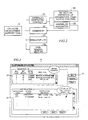
with reference to the drawings. FIG. 1 shows the development-support
system for a CPU core according to the present embodiment
with a structure of a peripheral equipment thereof. A CPU core
development support system 1 for supporting development of a CPU
core 3 on an FPGA (field programmable gate array) 2 which is a kind
of a logic integrated circuit, operates based on a CPU core
development support tool 6 which is installed in a personal computer
5 from a CD-ROM 4 (recording medium which records a CPU core
development support program in claims). The development support
system 1 comprises a CPU 7, a CD-ROM drive 8, a hard disk 10, a
memory 11, an input section 12 and a display unit 13, wherein the
CPU 7 executes entire control of the personal computer 5, the CD-ROM
drive 8 reads out various kinds of programs and data stored in
the CD-ROM 4, the hard disk 10 stores the CPU core development
support tool 6 or various kinds of files 9, the memory 11 is accessible
in high speed for temporarily storing various kinds of programs
which are stored in the hard disk 10, the input section 12 consists of
a key board, a mouse and so forth, and the display unit 13 consists of
a display, a printer and so forth. Further, the personal computer 5
has a communication driver 14 for communication through an RS-232C
interface. The communication driver 14 is connected to an
interface device 15 (ASAP: Adaptive Scan Agent Pod). The ASAP 15
is equipped with a special-purpose terminal for a boundary scan test,
which is called as TAP (Test Access Port), and connected to an ASH
(Adaptive Scan Handler) 16 in the FPGA 2. The ASH 16 is a module
for transmitting and receiving signals to and from the ASAP 15.
Data transmitted from the communication driver 14 of the personal
computer 5 is downloaded to the FPGA 2 through the ASAP 15 and
ASH 16.
-
Said CD-ROM 4 includes a source at a VHDL (VHSIC
hardware description language: one kind of hardware description
language) level as well as the CPU core development support tool 6.
Employing the development support system 1, the user can customize
the source at the VHDL level of the CPU core 3 which is read out from
the CD-ROM 4, adds, changes and deletes instructions which can be
used in an operating description program of the CPU core 3, and
examines the personal computer 5 (hereinafter referred to as offline
debugging) for the operating description program created by
themselves. Customized source at VHDL level of the CPU core 3 is
downloaded to the FPGA 2 through the communication driver 14,
interface device 15 and ASH 16 after logic synthesis. Also,
operating description program for which offline debugging is
completed, is also downloaded to the FPGA 2 through the same route
after assembled.
-
Next, referring to FIG. 2, the explanation is given to the
CPU core development support tool 6 (hereinafter referred to as
development support tool) which is installed in the personal
computer 5 from said CD-ROM 4. The CPU core development
support tool 6 comprises a compiler 21, an assembler 22, a simulator
section 23 and a VHDL renewal section 24 (renewal means in claims).
The compiler 21 (hereinafter, referred to as assembler generating
compiler) generates an assembler for a source program in assembly
language describing operations of the CPU core 3. The assembler 22
assembles the source program in assembly language describing
operations of the CPU core 3. The simulator section 23 is an
interpreter for sequentially interpreting and performing the source
program describing operations of the CPU core 3 on a step-by-step
basis. The VHDL renewal section 24 renews the source at VHDL
level of the CPU core 3 based on information directed by the user.
Further, the assembler generating compiler 21 comprises an MC
(Master C) section 25 and an assembler generator 26. The MC
section 25 defines a grammatical rule of assembly language that can
be used in operating description program of the CPU core 3, and
analyses syntaxes of said grammatical rule. The assembler
generator 26 generates a source program of the assembler in C-language
according to said grammatical rule based on the syntax
analysis of the grammatical rule by the MC section 25. Said
assembler 22 is composed of the object program created by compiling
the source program of the assembler generated by said assembler
generator 26.
-
Referring to FIG. 3, the customizing processing of the CPU
core 3 by means of said development-support tool 6 is nextly
explained. In order to customize the CPU core 3, it is generally
necessary to change operations of the instructions that can be used in
registers in the CPU core 3 or operating description program of the
CPU core 3. The development support tool 6 has a screen 31 for
customizing the CPU core 3, and the user employs a register defining
screen 32 (direction means in claims) and an instruction defining
screen 33 (defining means in claims) in said customizing screen 31,
thereby customizing registers in the CPU core 3, and instructions of
assembly language that can be used in the operating description
program of the CPU core 3. In order to customize registers, the user
inputs from the register defining screen 23 information about
addition, change or deletion of registers (hereinafter referred to as
register defining information). Also, in order to customize
instructions of assembly language, the user inputs from the
instruction defining screen 33 information about addition, change or
deletion of the assembly language (hereinafter referred to as
instruction defining information). After the user finishes inputting
these defining information, and clicks a setting button 34 through a
mouse included in the input section 12 shown in FIG. 1, the VHDL
renewal section 24 shown in FIG. 2 renews the source of VHDL level
of the CPU core 3 based on these defining information, and besides,
the assembler generating compiler 21 generates a source program of
the assembler 22 based on these defining information. Further, the
simulator section 23 gets in an available state for operation based on
these defining information.
-
Then, with reference to FIG. 4 as well as above FIG. 3,
customizing processing of the CPU core 3 is explained with showing a
specific example. As shown in FIG. 4, in the case of adding a new
register Z-REG 41 to a data path 40 of the CPU core 3, and at the
same time adding an LDZ (load Z register) instruction which loads
data to said Z-REG 41, it is necessary to change contents of an SA-MUX
42 as a multiplexer. In this case, if only the user inputs
information for adding the Z-REG 41 from the register defining
screen 32, and inputs information for adding the LDZ instruction
from the instruction defining screen 33, the VHDL renewal part 24
adds the Z-REG 41 into the source at VHDL level of the CPU core 3,
and changes contents of the SA-MUX 42 based on these information.
Also, the assembler generating compiler 21 generates assembler that
new grammatical rules are taken in correspondence with the addition
of the Z-REG 41 and LDZ instruction, based on information of adding
the Z-REG 41 and LDZ instruction that are respectively input from
the register defining screen 32 and instruction defining screen 33.
In accordance with this, the Z-REG 41 and LDZ instruction can be
used in the simulator section 23. In order to input information for
adding the LDZ instruction from the instruction defining screen 33,
the operation is defined by employing simplified language known as
MC (master C) language (refer to FIGS. 11 - 14). In said MC
language, only the register that is displayed in the register definition
screen 32 can be used.
-
Referring to FIG. 5, the explanation is nextly given to
offline debugging processing for the operating description program of
the CPU core 3 through the simulator section 23 shown in FIG. 2.
The simulator section 23 has a debugging screen 51, wherein the user
invokes a debugger set screen 53, an assembling direction screen 54,
and an editor screen (not shown) and the like from a pull-down menu
52 of the debugging screen 51, and carry out processing such as a
direction for the debugger (e.g., setting of a break point), correction
of the operating description program of the CPU core 3, assembly of
the corrected operating description program and so forth. Further,
the user can debug the operating description program by sequentially
interpreting and executing the operating description program in
step-by-step with the interpreter included in the simulator section 23.
Functions as a debugger included in the simulator section 23 are
basically similar to functions of a normal debugger such as setting of
a break point, tracing, a memory dump, memory rewriting and so
forth. However, the point which is different from functions of the
normal debugger is that the user can simulate input from another IP
57 (refer to FIG. 7) in the FPGA 2 in the debugging processing of the
present embodiment. Consequently, using the simulator section 23,
the user can examine the data generated in the CPU core 3 from the
IP 57. Furthermore, if the user directs to assemble the operating
description program from the assembling direction screen 54, the
assembler 22 classifies the label 56 in the operating description
language program into labels of a program segment and a data
segment, and creates a symbol table 67 (refer to FIG. 9) which
consists of sets of labels for each of segments. The simulator section
23 refers to the symbol table 67, thereby easily distinguishing
between labels of the program segment and data segment when the
interpreter interprets the operating description program. As
described above, it should be noted that the simulator section 23
operates based on information input from the register defining screen
32 and instruction defining screen 33 shown in FIG. 3.
-
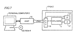
Next, with reference to FIGS. 6 and 7, the explanation is
given to the entire development processing of the CPU core 3 by the
CPU core development support system 1 according to the present
invention. Being different from a conventional CPU core
development support system in an ASIC and the like, the
development support system 1 according to the present invention
aims to customize the CPU core 3 according to specifications of
various kinds of the IPs 57 on the FPGA 2, and examine the CPU core
3 according to customized contents. Functions required in the CPU
core 3 generally differ in response to specifications of the IPs 57 as
targets. Accordingly, it is preferrable to change the architecture
and operating description program of the CPU core 3 in response to
the IPs 57 on the FPGA 2. Also, if the architecture and operating
description program of the CPU core 3 are changed, it is necessary to
change specifications of assembly language for the operating
description program and the assembler for said assembly language.
The development support system 1 makes it possible to customize and
examine the CPU core 3 in response to specifications of the IPs 57.
Concretely explaining, the user first determines registers in the CPU
core 3, and specifications of addition, change and deletion of
instructions (#1), and then, in response to the specifications,
customizes registers of the CPU core 3, and instructions of the
assembly language from the customizing screen 31 shown in FIG. 3,
besides carries out the offline debugging for the operating
description program from the debugging screen 51 shown in FIG. 5 in
response to specifications of the customized registers and
instructions of assembly language (#2). Next, the user creates the
source at VHDL level of the IPs 57 as targets (#3), and executes logic
synthesis of the source of said IPs 57 and the source at VHDL level in
the CPU core 3 renewed by the VHDL renewal section 24 (#4). Then,
as shown in FIG. 7, the user connects the FPGA 2 with the personal
computer 5 through the ASAP 15, and downloads the object program
of the operating description program which is debugged in offline in
#2, and the result of logic synthesis in #4 to the FPGA 2 (#5). Next,
the user carries out an actual CPU core 3 test (online debug) on the
FPGA 2 by transmitting and receiving data to and from the CPU core
3 on the FPGA 2 from the personal computer 5 in a state that the
personal computer 5 and the FPGA 2 are connected with each other
(#6).
-
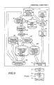
Referring to FIG. 8, the explanation is given to details of
customization and offline debugging procedure of the CPU core 3 in
#2 in FIG. 6. When the user displays the customizing screen 31
shown in FIG. 3, the CPU core development support tool 6 displays
register defining information in response to contents of a file
(hereinafter referred to as VHDL original source file) 61 which stores
VHDL source (VHDL source read out from the CD-ROM 4 in an initial
state) of the present CPU core 3. Further, the instruction defining
screen 33 displays instruction defining information in response to a
file (hereinafter referred to as basic grammatical rule file) 62 storing
basic grammatical rule (source of basic grammatical source in the
assembly language read out from the CD-ROM 4 in an initial state) of
the assembly language for the present operating description program.
After the user completes definitions of registers and the instruction
of the assembly language through the register defining screen 32 and
the instruction defining screen 33 (#11), the CPU core development
support tool 6 creates an instruction operating and register defining
file 64 storing these defining information, and at the same time
creates a file (hereinafter referred to as VHDL new source file) 63 of
VHDL source in the new CPU core 3 which reflects these defining
information. The assembler generating compiler 21 in the CPU core
development support tool 6 generates an augmented grammatical
rule which embodies new grammatical rule in the basic grammatical
rule of the assembly language in response to defining contents of new
registers and instructions of assembly language, and changes the
contents of the basic grammatical rule file 62 into said augmented
grammatical rules, and at the same time, generates a source program
of the assembler corresponding to said augmented grammatical rule
(#12). After that, it stores the created source program into an
assembler source file 68. The user compiles said assembler source,
thereby obtaining an object program of a desired assembler which
embodies a new grammatical rule (#13). Said object program of the
assembler is stored as an assembler object file 69 in the hard disk 10
shown in FIG. 1.
-
If the user inputs the source of operating description
program of the CPU core 3 (#14), and assembles said source of the
operating description program in the assembler 22 stored in the
assembler object file 69 (#15), the assembler 22 creates an object file
66 of operating description program, and at the same time, outputs
the symbol table 67 for offline debugging based on various kinds of
the labels 56 (refer to FIG. 5) in the source of the operating
description program. Next, using the debugging screen 51, the user
starts the offline debugging (#16), and using the interpreter function
of the simulator section 23, carries out each of instructions in a
source file 65 in operating description program in step-by-step (#17),
and then, carries out the operating description program. After that,
if the examined result of the operating description program includes
a problem (NO in #18), and it is necessary to customize the CPU core
3 (YES in #19), the procedure from #11 to #17 is repeated. If it is not
necessary to customize the CPU core 3, and the problem can be solved
by correcting operating description program (NO in #19), after the
user invokes an editing screen from the customizing screen 31, and
corrects the operating description program in said editing screen
(#20), the procedure from #15 to #17 is repeated.
-
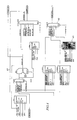
Next, referring to FIG. 9, the explanation is given to data
flows in the customizing procedure of said CPU core 3. In the figure,
it is to be noted that the same components as the previously-mentioned
ones are denoted by the same reference numerals. If,
using the register defining screen 32 and instruction defining screen
33 shown in FIG. 3, the user customizes registers and instructions of
assembly language, and creates the instruction operating and
register defining file 64, the assembler generating compiler 21
generates an augmented grammatical rule which embodies a new
grammatical rule, based on the instruction operating and register
defining file 64 and basic grammatical rule file 62, and rewrites the
contents of the basic grammatical rule file 62 into the augmented
grammatical rule; and at the same time, generates a source program
of the assembler in response to said grammatical rule, and outputs it
as the assembler source file 68. Based on said assembler source file
68, a compiler 70 outputs the assembler's object program (hereinafter
simply referred to as assembler) 22. Based on the source file 65 of
operating description program created by the user, said assembler 22
creates the file 66 which stores the object program of said operating
description program, and at the same time, classifies the label 56 in
the source of the operating description program into the label 56 of
the program segment and the label 56 of data segment, to thereby
create the symbol table 67 consisting of sets of the label 56 at every
segment. The simulator section 23 operates based on said symbol
table 67, instruction operating and register defining file 64 and
source file 65 of operating description program. After completing
the offline debugging by means of the simulator section 23, if the user
directs to download the contents of the operating description
program (object) file 66 into the FPGA 2, the CPU 7 of the personal
computer downloads the result of the logic synthesis into the FPGA 2
through the communication driver 14, ASAP 15 and ASH 16 in the
FPGA 2. Further, based on the instruction operation and register
defining file 64, the VHDL renewal section 24 renews the contents of
the VHDL original source file 61 corresponding to the circuit of the
CPU core 3, thereby creating a VHDL new source file. If the user
logically synthesizes the contents of the new source file 63 by using a
logic synthesis tool presented by an FPGA maker, and directs to
download the result of the logic synthesis to the FPGA 2, the CPU 7
in the personal computer downloads the result of the logic synthesis
to the FPGA 2 through the communication driver 14, ASAP 15 and
ASH 16 in the FPGA 2. Thus, using the communication driver 14
and the like, the user downloads the circuit of the new CPU core 3
and the operating description program of the CPU core 3 into the
FPGA 2, thereby making it possible to construct the CPU core 3 on
the FPGA 2, and start the online debugging for the CPU core 3.
-
Next, referring to FIG. 10, augmentation processing of
grammatical rule performed by the assembler generating compiler 21
is explained. If the user adds a new grammatical rule of assembly
language from the customizing screen 31 shown in FIG. 3, the
assembler generating compiler 21 generates a new augmented
grammatical rule II which embodies a new grammatical rule after
inheriting and succeeding a basic grammatical rule I of the assembly
language in MC language that is read from the basic grammatical
rule file 62. Further, if the user adds a new grammatical rule of
the assembly language from the customizing screen 31, the assembler
generating compiler 21 generates a re-augmented grammatical rule
III which embodies the new grammatical rule after inheriting and
succeeding the previously-given grammatical rules I and II. Thus, if
the user adds the new grammatical rule, the assembler generating
compiler 21 augments the grammatical rule so as to embody the new
grammatical rule after inheriting and succeeding the previously-given
grammatical rule, to thereby generate the source program of
assembler 22 corresponding to the augmented grammatical rule.
The user compiles the source program, thereby obtaining assembler
22 that corresponds to the augmented grammatical rule.
-
The grammatical rule stored in said basic grammatical
rule file 62 is created in MC language that is simplified language in a
description form similar to BNF (Buckus Normal Form). Based on
the source program of the basic grammatical rule of the assembly
language described in MC language read out from the basic
grammatical rule file 62, and new grammatical rule input from the
customizing screen 31 by the user, the assembler generating compiler
21 generates the source program of the augmented grammatical rule
in MC language, and renews the contents of the basic grammatical
rule file 62 into the source program of said augmented grammatical
rules, and at the same time, converts the source program described in
MC language into the source program of the assembler 22 described
in C language. The assembler generating compiler 21 reads the
renewed basic grammatical rule file 62, and extracts a literal train as
a token in a line-by-line, and creates a function of the assembler 22
in C language according to the rule of MC language.
-
Next, referring to FIG. 11, a description method of the
source program of the grammatical rule in MC language is explained.
When the user describes the source program in MC language, it is
necessary to describe the source program separately into a defining
segment 81 and a rule segment 82, and describe "End" in the end of a
sentence. The description method and grammar of the defining
segment 81 are same as in the case of C language. The user
describes variables used in the rule segment 82, definition such as
prototype declaration, or functions created by the user and used in
the rule segment 82, into the defining segment 81 in C language.
The assembler generating compiler 21 outputs the described contents
in said defining segment 81 as they are, into the source program of
the assembler 22. Besides, the user is required to describe the rule
segment 82 in MC language. The function in MC language described
in the rule segment 82 is converted into the function in C language by
the assembler generating compiler 21, and output into the source
program of the assembler 22. The user has to define a top function
created in MC language in a syntax sentence in the top of the rule
segment 82, and describe an End sentence in the end. In the case of
the source program shown in FIG. 14, sections from 83 to 87
correspond to the rule segment 82.
-
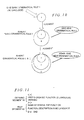
Referring to FIG. 12, a basic context in MC language is
explained. In the basic context in MC language, a left side is a name
of a function while a right side means processing of said function.
As shown in the figure, the user describes function 1 in the left side,
to thereby define contents of function 1. The contents of an upper
side of the basic context in the figure indicates that, executing
function 1 performs function 2, and when a return value of function 2
is 0, contents of <<sentence>> is performed. The contents of a lower
side indicates that, instead of processing by function 2, comparison
processing between a literal train ("letter") which is enclosed by
double quotation marks and an input token is carried out, and the
contents of <<sentence>> is also performed even in the case that
these are same as each other. This is because the contents that are
enclosed by double quotation marks are processed as a literal train
comparing function. Also, the contents of <<sentence>> is described
in C language, and output as they are by the assembler generating
compiler 21 in the source program of the assembler 22. The user
omits the description of function 2 in the upper side of the basic
contexts, thereby making it possible to unconditionally output the
contents of <<sentence>> in the source program of the assembler 22.
Besides, the end of function 1 is indicated by ";" as shown in the
figure. Following the definition of function 1 using function 2, the
user describes the definition of function 2 using function 3, and
further describes the definition of function 3 using function 4. In
such a way of hierarchically describing the processing of functions
one after another, it is possible to express the grammatical rule of the
desired assembly language. Return values of each of functions are
determined as 0 = normal finish, and 1 = error, so that the user has to
create the functions according to this rule. Besides, the user can
describe so as to correspond to selected processing by separating the
processing with "| " marks for describing plural functions in parallel.
For example, as shown in FIG. 13, the user can describe selecting
processing between "func1 <<f=1;>>" and "func2 <<f=2;>>" by
describing the "|" mark before func2.
-
Parenthesis marks and their meaning which can be used in
the
rule segment 82 in FIG. 11 are as follows:
- [1] {}: Repeat {} processing
- [2] []: Ignore return from [] processing
- [3] <<>>: Output <<>> processing into the source program
of the assembler 22 as they are
- [4] "": Compare between a literal train enclosed by "" and a
token
-
-
The
assembler generating compiler 21 has various kinds of
normal functions that can be used in the
rule segment 82 in FIG. 11.
In the
rule segment 82, the user can define the grammatical rule of
the assembly language by using these normal functions. Some of
these normal functions and their capabilities are indicated below:
- [1] McChkRsv(char*): Compare between input buffer and a
specified literal train. Input pointers are not
renewed.
- [2] McChkNm(void): Input a literal train in decimal
numbers, and check whether the input train is
numerals or not. Spaces between tokens are
automatically omitted to be read, and input pointers
are renewed.
- [3] McStop(char*): Display an error message, and finish
processing in case that an error occurs. Input
pointers are renewed.
-
-
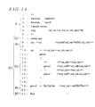
Next, referring to FIG. 14, an example of a simple
grammatical rule created in MC language is explained. "<<" in the
No. 1 line and ">>" in the No.6 line respectively indicate starting
positions of the defining segment 81 and rule segment 82, and the
No.2 to No.5 lines in the source program correspond to the defining
segment 81, and the No.7 to No.21 lines correspond to the rule
segment 82. Also, the rule segment 82 comprises the syntax
sentence 83, top function defining sentence 84, cal-function defining
sentence 85, getval-function defining sentence 86 and End sentence
87. The grammatical rule of the source program only permits
additions and subtractions, and performs additions and subtractions
based on input numerals, and "+" and "-" marks. If no error occurs,
a result of the calculation is displayed.
-
Next, the explanation is given to processing of each of
steps performed in the
rule segment 82 in the source program shown
in said FIG. 14.
- Line 7: Specify spa as a top function by a syntax sentence.
- Line 8: Defining processing of a top function spa.
Concretely, after the spa function is executed, cal
function is invoked, and if a return value of it is 0,
contents of a cal_val variation are displayed.
- Line 9: Terminate the spa function.
- Lines 10 - 17: Defining processing of a cal function.
Concretely, after the cal function is executed, the
top address of a cal_stk_spc array is set on a
cal_stk pointer (line 10), and a getval function
(function for reading numeric into the cal_val
variation) is invoked (line 11). Then, if a next
letter is "+", the value of the cal_val variation is
saved in a *cal_stk area (line 13), and the getval
function is again invoked. If return value of it is
0, the value of the cal_val variation is added to the
value of cal_stk area (line 14). On the other hand,
if the next letter is "-", the value of the cal_val
variation is saved in a *cal_stk area (line 15), and
the getval function is again invoked. If the
return value of it is 0, the value of the cal_val
variation is subtracted from the value of the
*cal_stk area (line 16). After that, the processing
from lines from 13 to 16 is repeated until the
termination of input.
- Line 18: Terminate the cal function.
- Line 19: Defining processing of a getval function.
Concretely, after the getval function is executed,
McChkNm function is invoked, and it is checked
whether input letter is numeral or not. If it is
numeral, a numerical value is read in the cal_val
variation.
- Line 20: Terminate the getval function.
- Line 21: Terminate the rule segment 82.
-
-
Based on the source program in MC language shown in FIG.
14, the assembler generating compiler 21 generates the source
program of the assembler 22 in C-language shown in FIGS. 15 - 17.
The defining segment 81 in FIG. 14 corresponds to a working section
91 in FIG. 15, and defining sentences 83 - 86 in FIG. 14 respectively
correspond to functions 93 - 96 in FIGS. 15 - 17. Thus, the
assembler generating compiler 21 generates the source program of
the assembler 22 in response to the grammatical rule given by the
user in MC language.
-
As described above, according to the CPU core
development support system 1 of the present embodiment, based on
the source program in MC language describing the basic grammatical
rule of assembly language that can be used in the CPU core 3, and
information about addition, changes or deletion of instructions of the
assembly language input from the instruction defining screen 33, the
assembler generating compiler 21 generates the source program of
the assembler 22 in which the new grammatical rule is taken in the
basic grammatical rule of the assembly language in correspondence
to information about addition, changes and deletion of the
instructions. Thus, the instructions of the assembly language that
is used in the CPU core 3 can be added, changed or deleted in
accordance with the specifications of other IPs 57 in the FPGA 2.
Further, based on information about addition, change or deletion of
the registers in the CPU core 3 that is directed by the user, VHDL
renewal section 24 renews the VHDL source of the CPU core 3,
thereby making it possible to easily add, change and delete the
registers in the CPU core 3 in accordance with the specifications of
other IPs 57 of the FPGA 2. This allows to easily construct the CPU
core 3 in response to the specifications of other IPs 57. Also, if there
is any unwanted register in the CPU core 3, the register can easily be
deleted from the source in the hardware description language level of
the CPU core 3, so that the simple CPU core 3 can be constructed on
the FPGA 2.
-
Having described preferred embodiments of the invention
with reference to the accompanying drawings, it is to be understood
that the invention is not limited to those precise embodiments, and
that various changes and modifications may be effected therein by
one skilled in the art without departing from the scope or spirit of the
invention as defined in the appended claims. Although the above
embodiment explained an example that an additional grammatical
rule is given from the customizing screen 31, it is also possible to
directly define an additional grammatical rule in MC language, and
generate the source program of the assembler 22 in which the new
grammatical rule is taken, based on said added grammatical rule and
a grammatical rule stored in the basic grammatical rule defining file
62.