EP1121902A2 - Pedicle screw - Google Patents
Pedicle screw Download PDFInfo
- Publication number
- EP1121902A2 EP1121902A2 EP01100933A EP01100933A EP1121902A2 EP 1121902 A2 EP1121902 A2 EP 1121902A2 EP 01100933 A EP01100933 A EP 01100933A EP 01100933 A EP01100933 A EP 01100933A EP 1121902 A2 EP1121902 A2 EP 1121902A2
- Authority
- EP
- European Patent Office
- Prior art keywords
- pedicle screw
- cap
- screw according
- round piece
- bracket part
- Prior art date
- Legal status (The legal status is an assumption and is not a legal conclusion. Google has not performed a legal analysis and makes no representation as to the accuracy of the status listed.)
- Granted
Links
- 239000007943 implant Substances 0.000 claims abstract description 4
- 230000000903 blocking effect Effects 0.000 claims description 2
- 230000006641 stabilisation Effects 0.000 claims 1
- 238000011105 stabilization Methods 0.000 claims 1
- 230000000087 stabilizing effect Effects 0.000 abstract 1
- 238000001356 surgical procedure Methods 0.000 description 2
- 230000009286 beneficial effect Effects 0.000 description 1
- 230000005540 biological transmission Effects 0.000 description 1
- 230000001771 impaired effect Effects 0.000 description 1
- 230000002045 lasting effect Effects 0.000 description 1
- 238000000034 method Methods 0.000 description 1
- 230000002028 premature Effects 0.000 description 1
Images


Classifications
-
- A—HUMAN NECESSITIES
- A61—MEDICAL OR VETERINARY SCIENCE; HYGIENE
- A61B—DIAGNOSIS; SURGERY; IDENTIFICATION
- A61B17/00—Surgical instruments, devices or methods, e.g. tourniquets
- A61B17/56—Surgical instruments or methods for treatment of bones or joints; Devices specially adapted therefor
- A61B17/58—Surgical instruments or methods for treatment of bones or joints; Devices specially adapted therefor for osteosynthesis, e.g. bone plates, screws, setting implements or the like
- A61B17/68—Internal fixation devices, including fasteners and spinal fixators, even if a part thereof projects from the skin
- A61B17/70—Spinal positioners or stabilisers ; Bone stabilisers comprising fluid filler in an implant
- A61B17/7001—Screws or hooks combined with longitudinal elements which do not contact vertebrae
- A61B17/7035—Screws or hooks, wherein a rod-clamping part and a bone-anchoring part can pivot relative to each other
- A61B17/7037—Screws or hooks, wherein a rod-clamping part and a bone-anchoring part can pivot relative to each other wherein pivoting is blocked when the rod is clamped
-
- A—HUMAN NECESSITIES
- A61—MEDICAL OR VETERINARY SCIENCE; HYGIENE
- A61B—DIAGNOSIS; SURGERY; IDENTIFICATION
- A61B17/00—Surgical instruments, devices or methods, e.g. tourniquets
- A61B17/56—Surgical instruments or methods for treatment of bones or joints; Devices specially adapted therefor
- A61B17/58—Surgical instruments or methods for treatment of bones or joints; Devices specially adapted therefor for osteosynthesis, e.g. bone plates, screws, setting implements or the like
- A61B17/68—Internal fixation devices, including fasteners and spinal fixators, even if a part thereof projects from the skin
- A61B17/70—Spinal positioners or stabilisers ; Bone stabilisers comprising fluid filler in an implant
- A61B17/7001—Screws or hooks combined with longitudinal elements which do not contact vertebrae
- A61B17/7032—Screws or hooks with U-shaped head or back through which longitudinal rods pass
-
- A—HUMAN NECESSITIES
- A61—MEDICAL OR VETERINARY SCIENCE; HYGIENE
- A61B—DIAGNOSIS; SURGERY; IDENTIFICATION
- A61B17/00—Surgical instruments, devices or methods, e.g. tourniquets
- A61B17/56—Surgical instruments or methods for treatment of bones or joints; Devices specially adapted therefor
- A61B17/58—Surgical instruments or methods for treatment of bones or joints; Devices specially adapted therefor for osteosynthesis, e.g. bone plates, screws, setting implements or the like
- A61B17/68—Internal fixation devices, including fasteners and spinal fixators, even if a part thereof projects from the skin
- A61B17/70—Spinal positioners or stabilisers ; Bone stabilisers comprising fluid filler in an implant
- A61B17/7001—Screws or hooks combined with longitudinal elements which do not contact vertebrae
- A61B17/7035—Screws or hooks, wherein a rod-clamping part and a bone-anchoring part can pivot relative to each other
- A61B17/7038—Screws or hooks, wherein a rod-clamping part and a bone-anchoring part can pivot relative to each other to a different extent in different directions, e.g. within one plane only
Definitions
- the invention relates to a pedicle screw for implants to correct and stabilize the spine, with one at the axial end of a threaded shaft arranged head part, to which a bracket part can be connected is that a holder for a fixable on the headboard Rod.
- Such pedicle screws are for example from DE 41 07 480 A1 known. With these known Pedicle screws overlap the bow part with the head part lateral leg parts in which parallel to Longitudinal direction of the rod, open on one side Grooves are formed in the provided on the head part and intervene in correspondingly running strips, the bars and to avoid spreading Grooves on their abutting leg parts have dovetail-like undercuts. This Pedicle screws have proven themselves well in practice because it is possible with these, a stable and lasting To allow fixation of the position of the rod.
- the invention is therefore based on the object To design pedicle screws of the type mentioned at the beginning that the space required for the placement and adjustment of the Pedicle screw is reduced during surgery.
- the invention offers the advantage that after placing the pedicle screws in the vertebral body and the Position the rod the other required Measures taken by the surgeon only in the longitudinal direction of the Threaded shaft must be carried out, i.e. opposite the space for screwing in the anyway Pedicle screws are needed, no additional space is required.
- An individual adjustment is required the course of the usually curved rod possible because in addition to the appropriate choice of the rotational position of the threaded shaft the pedicle screw with the head part additionally the cap can be rotated around the round piece.
- the rotatability thus given is subject to the least Restrictions when using the round piece as a hemisphere oriented perpendicular to the threaded shaft, to the free one End facing flat surface is formed.
- bracket part with a U-shape a base plate and two side legs is formed, at their free ends locking lugs are formed, which for Training of the rest seat during the plug-in movement on the Hook the cap on.
- the means Provide rotatability of the cap on the round piece.
- These are expediently designed so that the mutually facing surfaces of the round piece and the Cap have a surface profile, and that in a threaded hole in the base plate of the bracket part is designed for one of the fixation of the rod Locking screw.
- the cap is a gutter has as a support for the rod.
- the rod is to immediate transmission of those acting on the rod Forces on the pedicle screw or the calotte in the Channel formed an opening.
- bracket part Attaching the bracket part to the cap, to the one slight spreading of the side legs is required is facilitated by the fact that between the base plate and a groove is formed on the side legs.
- the pedicle screw according to the invention is still like this designed that the headboard at a taper of the Threaded shaft is attached. This has the advantage that the cap over a larger angular range on the Round piece can be adjusted without the cap on the Threaded shaft comes to rest.
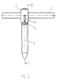
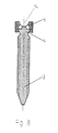
- the pedicle screw 1 shown in FIG. 1 is used in connection with implants, the correction and stabilize the spine and serve it a rod 2 guided along the spine use.
- the pedicle screw 1 consists of a Threaded shaft 3, at one axial end through a round piece 4 and a cap 6 formed head part 5 is arranged.
- the round piece 4 is a hemisphere 20 formed, the flat surface 22 perpendicular to the Threaded shaft 3 is oriented and points outwards.
- On the flat surface 22 of the hemisphere 20 is a spherical cap 23 arranged, whose diameter is smaller than that of Hemisphere 20 is. From this structure it follows that the Cap 6 rotatable polyaxially around the round piece 4 and one good adaptability to the location of the Spine along rod 2 is given (Fig. 3,8,10).
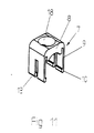
- the arranged on the round piece 4 cap 6 is one U-shaped bracket part 7, which accommodates provides the rod 2.
- the bracket part 7 consists of a Base plate 8 and two side legs 9, at their free Ends locking lugs 10 are formed.
- the locking lugs 10 at the edges of the End plates 11 assigned to cap 6 in a rest position hook up.
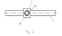
- Threaded bore 18 serves to receive a Locking screw 19 with which the rod 2 against Shifts in its longitudinal direction are secured can.
- This locking screw 19 clamped in The bracket part 7 also interacts with the locking lugs 10 opposite the cap 6, which is also used to to press the cap 6 against the hemisphere 20. If according to one embodiment, the mutually facing Surfaces of the round piece 4 and the cap 6 a Having surface profiling, this acts as a means to block the rotatability of the cap 6 and the Round piece 4, the design of the Surface profiling leaves the possibility open that Complete rotatability, with respect to several axes or can only be prevented with respect to one axis.
- the Cap 6 a channel 14 as a support for the rod 2.
- the Enclosure of the rod 2 by the pedicle screw 1 by a in the base plate 8 of the bracket part 7 trained gutter 16 completed.
- FIGS. 5 to 10 can also be seen that the head part 5 on a Taper 21 of the threaded shaft 3 is attached, the The angle of rotation of the cap 6 is therefore not premature due to this System on the threaded shaft 3 is limited.
Abstract
Die Erfindung betrifft eine Pedikelschraube für Implantate zur Korrektur und Stabilisierung der Wirbelsäule. Diese Pedikelschraube besitzt ein an dem axialen Ende eines Gewindeschafts (3) angeordnetes Kopfteil (5), an dem ein Bügelteil (7) anschließbar ist, das eine Aufnahme für einen am Kopfteil (5) fixierbaren Stab (2) aufweist. Das Kopfteil (5) ist durch ein Rundstück (4) und eine drehbar auf dem Rundstück (4) gelagerten Kappe (6) gebildet. Das Bügelteil (7) ist durch eine in axialer Richtung erfolgende Steckbewegung in einem Rastsitz an der Kappe (6) fixierbar. <IMAGE>The invention relates to a pedicle screw for implants for correcting and stabilizing the spine. This pedicle screw has a head part (5) arranged on the axial end of a threaded shaft (3), to which a bracket part (7) can be connected, which has a receptacle for a rod (2) which can be fixed to the head part (5). The head part (5) is formed by a round piece (4) and a cap (6) rotatably mounted on the round piece (4). The bracket part (7) can be fixed in a detent seat on the cap (6) by an axial plug-in movement. <IMAGE>
Description
Die Erfindung betrifft eine Pedikelschraube für Implantate zur Korrektur und Stabilisierung der Wirbelsäule, mit einem an dem axialen Ende eines Gewindeschafts angeordneten Kopfteil, an dem ein Bügelteil anschließbar ist, das eine Aufnahme für einen am Kopfteil fixierbaren Stab aufweist.The invention relates to a pedicle screw for implants to correct and stabilize the spine, with one at the axial end of a threaded shaft arranged head part, to which a bracket part can be connected is that a holder for a fixable on the headboard Rod.
Derartige Pedikelschrauben sind beispielsweise aus der DE 41 07 480 A1 bekannt. Bei diesen bekannten Pedikelschrauben übergreift das Bügelteil das Kopfteil mit seitlichen Schenkelteilen, in denen parallel zur Längsrichtung des Stabes verlaufende, einseitig offene Nuten ausgebildet sind, in die am Kopfteil vorgesehene und entsprechend verlaufende Leisten formschlüssig eingreifen, wobei zur Vermeidung von Abspreizungen die Leisten und Nuten an ihren aneinanderliegenden Schenkelteilen schwalbenschwanzartige Hinterschneidungen aufweisen. Diese Pedikelschrauben haben sich in der Praxis gut bewährt, da es mit diesen möglich ist, eine stabile und dauerhafte Fixierung der Lage des Stabes zu ermöglichen. Allerdings ist für die Plazierung und gegenseitige Fixierung von der Pedikelschraube und dem Stab während der Operation relativ viel Raum erforderlich, wobei es infolge der Krümmung der Wirbelsäule und der geneigt zur Längsachse der Wirbelkörper eingesetzten Pedikelschrauben möglich ist, daß die bereits plazierten Pedikelschrauben die Plazierung der Pedikelschrauben am unmittelbar benachbarten Wirbel behindern oder sogar verhindern.Such pedicle screws are for example from DE 41 07 480 A1 known. With these known Pedicle screws overlap the bow part with the head part lateral leg parts in which parallel to Longitudinal direction of the rod, open on one side Grooves are formed in the provided on the head part and intervene in correspondingly running strips, the bars and to avoid spreading Grooves on their abutting leg parts have dovetail-like undercuts. This Pedicle screws have proven themselves well in practice because it is possible with these, a stable and lasting To allow fixation of the position of the rod. Indeed is for the placement and mutual fixation of the Pedicle screw and the rod during surgery relatively much space is required, being due to the curvature of the Spine and the inclined to the longitudinal axis of the Vertebral body inserted pedicle screws is possible that the already placed pedicle screws are the placement the pedicle screws on the immediately adjacent vertebra hinder or even prevent.
Der Erfindung liegt daher die Aufgabe zugrunde, eine Pedikelschraube der eingangs genannten Art so auszubilden, daß der Raumbedarf für die Plazierung und Justierung der Pedikelschraube während der Operation verringert ist.The invention is therefore based on the object To design pedicle screws of the type mentioned at the beginning that the space required for the placement and adjustment of the Pedicle screw is reduced during surgery.
Diese Aufgabe wird nach der Erfindung bei einer Pedikelschraube der eingangs genannten Art dadurch gelöst, daß das Kopfteil durch ein Rundstück und eine drehbar auf dem Rundstück gelagerten Kappe gebildet ist, und daß das Bügelteil durch eine in axialer Richtung erfolgende Steckbewegung in einem Rastsitz an der Kappe fixierbar ist.This object is achieved according to the invention in a Loosened pedicle screw of the type mentioned above, that the head part by a round piece and a rotatable the round bearing cap is formed, and that Bracket part by an axially Plug-in movement can be fixed to the cap in a snap-in seat is.
Die Erfindung bietet den Vorteil, daß nach dem Plazieren der Pedikelschrauben in dem Wirbelkörper und der Positionierung des Stabes die weiteren erforderlichen Maßnahmen des Operateurs nur in der Längsrichtung des Gewindeschaftes durchgeführt werden müssen, also gegenüber dem Raum der ohnehin für das Einschrauben der Pedikelschrauben benötigt wird, kein zusätzlicher Raum erforderlich ist. Dabei ist eine individuelle Anpassung an den Verlauf des in der Regel gekrümmten Stabes möglich, da neben der geeigneten Wahl der Drehlage des Gewindeschaftes der Pedikelschraube mit dem Kopfteil zusätzlich die Kappe um das Rundstück verdreht werden kann.The invention offers the advantage that after placing the pedicle screws in the vertebral body and the Position the rod the other required Measures taken by the surgeon only in the longitudinal direction of the Threaded shaft must be carried out, i.e. opposite the space for screwing in the anyway Pedicle screws are needed, no additional space is required. An individual adjustment is required the course of the usually curved rod possible because in addition to the appropriate choice of the rotational position of the threaded shaft the pedicle screw with the head part additionally the cap can be rotated around the round piece.
Die so gegebene Verdrehbarkeit unterliegt den geringsten Einschränkungen, wenn das Rundstück als Halbkugel mit senkrecht zu dem Gewindeschaft orientierter, zum freien Ende weisender Planfläche ausgebildet ist.The rotatability thus given is subject to the least Restrictions when using the round piece as a hemisphere oriented perpendicular to the threaded shaft, to the free one End facing flat surface is formed.
Ist zusätzlich auf der Planfläche eine Kalotte mit gegenüber der Halbkugel geringeren Durchmessers angeordnet, besteht die Möglichkeit, den Stab an einem Auflagepunkt unmittelbar durch das Rundstück abzustützen, wobei die Drehbarkeit infolge des kleinen Durchmessers der Kalotte für den Stab relativ zum Rundstück nicht beeinträchtigt ist.Is a calotte also on the flat surface compared to the hemisphere of smaller diameter arranged, it is possible to attach the rod to a Support the support point directly through the round piece, the rotatability due to the small diameter of the Dome for the rod not relative to the round piece is impaired.
Nach einer besonders bevorzugten Ausführungsform der Erfindung ist vorgesehen, daß das Bügelteil U-förmig mit einer Grundplatte und zwei Seitenschenkeln gebildet ist, an deren freien Enden Rastnasen ausgebildet sind, die zur Ausbildung des Rastsitzes bei der Steckbewegung an dem Kappe einhaken.According to a particularly preferred embodiment of the Invention is provided that the bracket part with a U-shape a base plate and two side legs is formed, at their free ends locking lugs are formed, which for Training of the rest seat during the plug-in movement on the Hook the cap on.
Um eine ungewollte Verdrehung der Kappe zu verhindern, besteht die Möglichkeit, Mittel zur Blockade der Drehbarkeit von der Kappe auf dem Rundstück vorzusehen. Diese sind zweckmäßigerweise so gestaltet, daß die einander zugewandten Oberflächen von dem Rundstück und der Kappe eine Oberflächenprofilierung aufweisen, und daß in der Grundplatte des Bügelteils eine Gewindebohrung ausgebildet ist für eine der Fixierung des Stabes dienende Sicherungsschraube. Sobald beim Einschrauben der Sicherungsschraube diese an dem Stab zu Anlage kommt, wird der Stab gegen das Rundstück gepreßt, während die Sicherungsschraube sich an dem Stab abstützt und damit auch das Bügelteil gegen die Kappe verspannt, die somit gleichfalls an der dem Stab gegenüberliegenden Seite an das Rundstück gepreßt wird, was mit der geeigneten Oberflächenprofilierung ausgenutzt wird, die Drehbarkeit zu beschränken.To prevent unwanted twisting of the cap, there is a possibility of blocking the means Provide rotatability of the cap on the round piece. These are expediently designed so that the mutually facing surfaces of the round piece and the Cap have a surface profile, and that in a threaded hole in the base plate of the bracket part is designed for one of the fixation of the rod Locking screw. As soon as you screw in the Locking screw that comes into contact with the rod the rod pressed against the round piece, while the Locking screw is supported on the rod and thus also clamped the bracket part against the cap, which thus likewise on the side opposite the rod the round piece is pressed, what with the appropriate Surface profiling is used, the rotatability to restrict.
Um einen genau definierten Sitz des Bügelteiles auf der Kappe dauerhaft zu gewährleisten, ist die Pedikelschraube so gestaltet, daß an der Kappe Endplatten mit jeweils einem in axialer Richtung verlaufenden Führungssteg angeordnet sind, und daß jeder Seitenschenkel eine Führungsnut für den Führunssteg aufweist. Alternativ besteht zum Erreichen dieses Zieles natürlich auch die Möglichkeit, daß die Führungsstege und die Führungsnuten an den Endplatten und den Seitenschenkeln miteinander vertauscht sind.To ensure a precisely defined fit of the bracket part on the The pedicle screw is to ensure the cap permanently designed so that end plates with each on the cap a guide web extending in the axial direction are arranged, and that each side leg a Has guide groove for the guide bar. Alternatively there is of course also to achieve this goal Possibility that the guide webs and the guide grooves on the end plates and the side legs together are reversed.
Zur Vermeidung einer Aufspreizung der Seitenschenkel bei in axialer Richtung auf das Bügelteil einwirkenden Kräften ist vorgesehen, daß die Rastnasen die freien Kanten der Endplatten hintergreifen.To avoid spreading the side legs Forces acting on the bracket part in the axial direction it is provided that the locking lugs the free edges of the Reach behind the end plates.
Im Hinblick auf eine möglichst großflächig verteilte Krafteinleitung ist es günstig, wenn die Kappe eine Rinne als Auflager für den Stab aufweist. Dabei ist zur unmittelbaren Übertragung von auf den Stab einwirkenden Kräfte auf die Pedikelschraube bzw die Kalotte in der Rinne eine Öffnung ausgebildet. With a view to the largest possible distribution It is beneficial if the cap is a gutter has as a support for the rod. Here is to immediate transmission of those acting on the rod Forces on the pedicle screw or the calotte in the Channel formed an opening.
Um den Stab in Umfangsrichtung möglichst weit umfassen zu können, ist in der Grundplatte des Bügelteils eine Rinne ausgebildet.To encompass the rod as far as possible in the circumferential direction can, there is a gutter in the base plate of the bracket part educated.
Das Aufstecken des Bügelteils auf die Kappe, zu dem eine leichte Aufspreizung der Seitenschenkel erforderlich ist, wird dadurch erleichtert, daß zwischen der Grundplatte und den Seitenschenkeln eine Nut ausgebildet ist.Attaching the bracket part to the cap, to the one slight spreading of the side legs is required is facilitated by the fact that between the base plate and a groove is formed on the side legs.
Die erfindungsgemäße Pedikelschraube ist weiterhin so gestaltet, daß das Kopfteil an einer Verjüngung des Gewindeschafts angesetzt ist. Dies bietet den Vorteil, daß die Kappe über einen größeren Winkelbereich auf dem Rundstück verstellt werden kann, ohne daß die Kappe an dem Gewindeschaft zur Anlage kommt.The pedicle screw according to the invention is still like this designed that the headboard at a taper of the Threaded shaft is attached. This has the advantage that the cap over a larger angular range on the Round piece can be adjusted without the cap on the Threaded shaft comes to rest.
Im folgenden wird die Erfindung an einem in der Zeichnung dargestellten Ausführungsbeispiel näher erläutert; es zeigen:
- Fig. 1
- eine perspektivische Darstellung der erfindungsgemäßen Pedikelschraube mit einem am Kopfteil fixierten Stab,
- Fig. 2
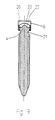
- eine Seitenansicht der Pedikelschraube,
- Fig. 3
- der Schnitt III-III aus Fig. 2,
- Fig. 4
- eine Draufsicht auf die Pedikelschraube aus Fig. 2,
- Fig. 5
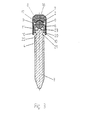
- eine Seitenansicht des Gewindeschaftes mit dem Kopfteil,
- Fig. 6
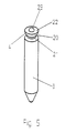
- eine perspektivische Darstellung der auf das Rundstück aufgesetzten Kappe,
- Fig. 7
- eine weitere perspektivische Darstellung der Pedikelschraube aus Fig. 6 aus einem anderen Blickwinkel,
- Fig. 8
- der Schnitt VIII-VIII aus Fig. 7,
- Fig. 9
- der Schnitt IX-IX aus Fig. 7
- Fig. 10
- eine der Fig. 9 entsprechende Darstellung mit einer gegenüber Fig. 9 verdrehten Kappe, und
- Fig. 11
- eine perspektivischen Darstellung des U-förmigen Bügelteils.
- Fig. 1
- 2 shows a perspective view of the pedicle screw according to the invention with a rod fixed to the head part,
- Fig. 2
- a side view of the pedicle screw,
- Fig. 3
- the section III-III of Fig. 2,
- Fig. 4
- 3 shows a plan view of the pedicle screw from FIG. 2,
- Fig. 5
- a side view of the threaded shaft with the head part,
- Fig. 6
- a perspective view of the cap placed on the round piece,
- Fig. 7
- 6 shows a further perspective view of the pedicle screw from FIG. 6 from a different perspective,
- Fig. 8
- the section VIII-VIII of Fig. 7,
- Fig. 9
- the section IX-IX from FIG. 7
- Fig. 10
- 9 shows a representation corresponding to FIG. 9 with a cap rotated relative to FIG. 9, and
- Fig. 11
- a perspective view of the U-shaped bracket part.
Die in der Fig. 1 dargestellte Pedikelschraube 1 wird
benutzt im Zusammenhang mit Implantaten, die der Korrektur
und Stabilisierung der Wirbelsäule dienen und die dazu
einen an der Wirbelsäule entlanggeführten Stab 2
verwenden. Die Pedikelschraube 1 besteht aus einem
Gewindeschaft 3, an dessen einem axialen Ende ein durch
ein Rundstück 4 und eine Kappe 6 gebildetes Kopfteil 5
angeordnet ist. Dabei ist das Rundstück 4 als Halbkugel 20
ausgebildet, deren Planfläche 22 senkrecht zu dem
Gewindeschaft 3 orientiert ist und nach außen weist. Auf
der Planfläche 22 der Halbkugel 20 ist eine Kalotte 23
angeordnet, deren Durchmesser kleiner als der der
Halbkugel 20 ist. Aus diesem Aufbau ergibt sich, daß die
Kappe 6 polyaxial um das Rundstück 4 verdrehbar und eine
gute Anpassungsmöglichkeit an die Lage des an der
Wirbelsäule entlanggeführten Stabes 2 gegeben ist
(Fig. 3,8,10).The pedicle screw 1 shown in FIG. 1 is
used in connection with implants, the correction
and stabilize the spine and serve it
a rod 2 guided along the spine
use. The pedicle screw 1 consists of a
Threaded shaft 3, at one axial end through
a round piece 4 and a
Die auf dem Rundstück 4 angeordnete Kappe 6 wird von einem
U-förmigen Bügelteil 7 übergriffen, das eine Aufnahme für
den Stab 2 bereitstellt. Das Bügelteil 7 besteht aus einer
Grundplatte 8 und zwei Seitenschenkeln 9, an deren freien
Enden Rastnasen 10 ausgebildet sind. Zur Fixierung des
Bügelteils 7 wird dieses durch eine ausschließlich in
axialer Richtung erfolgende Steckbewegung auf die Kappe 6
aufgesteckt, wobei die Rastnasen 10 an den Kanten von der
Kappe 6 zugeordneten Endplatten 11 in einem Rastsitz
einhaken. Um eine lagerichtige Verbindung des Bügelteils 7
mit der Kappe 6 zu gewährleisten, sowie um ein Verschieben
des Bügelteiles 7 in Längsrichtung des Stabes 2 zu
vermeiden, sind an den Endplatten 11 Führungsstege 12
ausgebildet, die mit einer Führungsnut 13 zusammenwirken,
die an den Seitenschenkeln 9 des Bügelteils 7 ausgebildet
sind. Nach einer selber nicht in der Zeichnung
dargestellten Ausführungsform ist es selbstverständlich
auch möglich, daß die Führungsstege 12 und die
Führungsnuten 13 an den Endplatten 11 und den
Seitenschenkeln 9 miteinander vertauscht sind.The arranged on the round piece 4
Eine in der Grundplatte 8 des Bügelteils 7 angeordnete
Gewindebohrung 18 dient zur Aufnahme einer
Sicherungsschraube 19, mit der der Stab 2 gegen
Verschiebungen in seiner Längsrichtung gesichert werden
kann. Diese Sicherungsschraube 19 verspannt im
Zusammenwirken mit den Rastnasen 10 auch das Bügelteil 7
gegenüber der Kappe 6, was weiterhin dazu ausgenutzt wird,
um die Kappe 6 gegen die Halbkugel 20 zu pressen. Wenn
nach einer Ausführungsform die einander zugewandten
Oberflächen von dem Rundstück 4 und der Kappe 6 eine
Oberflächenprofilierung aufweisen, wirkt dies als Mittel
zur Blockade der Drehbarkeit von der Kappe 6 und dem
Rundstück 4, wobei die Gestaltung der
Oberflächenprofilierung die Möglichkeit offenläßt, die
Drehbarkeit vollständig, hinsichtlich mehrerer Achsen oder
nur hinsichtlich einer Achse zu unterbinden.One arranged in the base plate 8 of the
Wie insbesondere aus Fig. 7 ersichtlich ist, weist die
Kappe 6 eine Rinne 14 als Auflager für den Stab 2 auf. Die
Umfassung des Stabes 2 durch die Pedikelschraube 1 wird
durch eine in der Grundplatte 8 des Bügelteils 7
ausgebildete Rinne 16 komplettiert.As can be seen in particular from FIG. 7, the
Cap 6 a
Aus den Fig. 1, 3 und 11 ist ersichtlich, daß am
Bügelteil 7 zwischen der Grundplatte 8 und den
Seitenschenkeln 9 eine Nut 17 ausgebildet ist, die das
Aufspreizen des Bügelteil 7 beim Aufsteckvorgang
erleichtert. Ein unerwünschtes Aufspreizen nach dem
Aufstecken des Bügelteils 7 wird dadurch verhindert, daß
die Rastnasen 10 die freien Kanten der Endplatten 11
hintergreifen.1, 3 and 11 it can be seen that on
Aus der Zeichnung, insbesondere den Fig. 5 bis 10 ist
weiterhin ersichtlich, daß das Kopfteil 5 an einer
Verjüngung 21 des Gewindeschaftes 3 angesetzt ist, der
Drehwinkel der Kappe 6 also nicht frühzeitig durch dessen
Anlage an dem Gewindeschaft 3 begrenzt ist.From the drawing, in particular FIGS. 5 to 10
can also be seen that the head part 5 on a
Claims (14)
Applications Claiming Priority (2)
| Application Number | Priority Date | Filing Date | Title |
|---|---|---|---|
| DE10005385 | 2000-02-07 | ||
| DE10005385A DE10005385A1 (en) | 2000-02-07 | 2000-02-07 | Pedicle screw |
Publications (3)
| Publication Number | Publication Date |
|---|---|
| EP1121902A2 true EP1121902A2 (en) | 2001-08-08 |
| EP1121902A3 EP1121902A3 (en) | 2002-02-06 |
| EP1121902B1 EP1121902B1 (en) | 2004-09-22 |
Family
ID=7630128
Family Applications (1)
| Application Number | Title | Priority Date | Filing Date |
|---|---|---|---|
| EP01100933A Expired - Lifetime EP1121902B1 (en) | 2000-02-07 | 2001-01-17 | Pedicle screw |
Country Status (5)
| Country | Link |
|---|---|
| US (1) | US6402752B2 (en) |
| EP (1) | EP1121902B1 (en) |
| AT (1) | ATE276705T1 (en) |
| DE (2) | DE10005385A1 (en) |
| ES (1) | ES2223651T3 (en) |
Cited By (32)
| Publication number | Priority date | Publication date | Assignee | Title |
|---|---|---|---|---|
| US6716214B1 (en) | 2003-06-18 | 2004-04-06 | Roger P. Jackson | Polyaxial bone screw with spline capture connection |
| US7322981B2 (en) | 2003-08-28 | 2008-01-29 | Jackson Roger P | Polyaxial bone screw with split retainer ring |
| US7513905B2 (en) | 2004-11-03 | 2009-04-07 | Jackson Roger P | Polyaxial bone screw |
| US7572279B2 (en) | 2004-11-10 | 2009-08-11 | Jackson Roger P | Polyaxial bone screw with discontinuous helically wound capture connection |
| US7625396B2 (en) | 2004-11-23 | 2009-12-01 | Jackson Roger P | Polyaxial bone screw with multi-part shank retainer |
| US7776067B2 (en) | 2005-05-27 | 2010-08-17 | Jackson Roger P | Polyaxial bone screw with shank articulation pressure insert and method |
| US7789896B2 (en) | 2005-02-22 | 2010-09-07 | Jackson Roger P | Polyaxial bone screw assembly |
| US7833250B2 (en) | 2004-11-10 | 2010-11-16 | Jackson Roger P | Polyaxial bone screw with helically wound capture connection |
| US8052724B2 (en) | 2003-06-18 | 2011-11-08 | Jackson Roger P | Upload shank swivel head bone screw spinal implant |
| US8137386B2 (en) | 2003-08-28 | 2012-03-20 | Jackson Roger P | Polyaxial bone screw apparatus |
| CN104939902A (en) * | 2015-05-06 | 2015-09-30 | 山东威高骨科材料股份有限公司 | Single-plane pedicle screw |
| US9629669B2 (en) | 2004-11-23 | 2017-04-25 | Roger P. Jackson | Spinal fixation tool set and method |
| USRE46431E1 (en) | 2003-06-18 | 2017-06-13 | Roger P Jackson | Polyaxial bone anchor with helical capture connection, insert and dual locking assembly |
| US9907574B2 (en) | 2008-08-01 | 2018-03-06 | Roger P. Jackson | Polyaxial bone anchors with pop-on shank, friction fit fully restrained retainer, insert and tool receiving features |
| US9918751B2 (en) | 2004-02-27 | 2018-03-20 | Roger P. Jackson | Tool system for dynamic spinal implants |
| US9918745B2 (en) | 2009-06-15 | 2018-03-20 | Roger P. Jackson | Polyaxial bone anchor with pop-on shank and winged insert with friction fit compressive collet |
| US9980753B2 (en) | 2009-06-15 | 2018-05-29 | Roger P Jackson | pivotal anchor with snap-in-place insert having rotation blocking extensions |
| US10039577B2 (en) | 2004-11-23 | 2018-08-07 | Roger P Jackson | Bone anchor receiver with horizontal radiused tool attachment structures and parallel planar outer surfaces |
| US10039578B2 (en) | 2003-12-16 | 2018-08-07 | DePuy Synthes Products, Inc. | Methods and devices for minimally invasive spinal fixation element placement |
| US10076361B2 (en) | 2005-02-22 | 2018-09-18 | Roger P. Jackson | Polyaxial bone screw with spherical capture, compression and alignment and retention structures |
| US10194951B2 (en) | 2005-05-10 | 2019-02-05 | Roger P. Jackson | Polyaxial bone anchor with compound articulation and pop-on shank |
| US10258382B2 (en) | 2007-01-18 | 2019-04-16 | Roger P. Jackson | Rod-cord dynamic connection assemblies with slidable bone anchor attachment members along the cord |
| US10299839B2 (en) | 2003-12-16 | 2019-05-28 | Medos International Sárl | Percutaneous access devices and bone anchor assemblies |
| US10363070B2 (en) | 2009-06-15 | 2019-07-30 | Roger P. Jackson | Pivotal bone anchor assemblies with pressure inserts and snap on articulating retainers |
| US10383660B2 (en) | 2007-05-01 | 2019-08-20 | Roger P. Jackson | Soft stabilization assemblies with pretensioned cords |
| US10470801B2 (en) | 2007-01-18 | 2019-11-12 | Roger P. Jackson | Dynamic spinal stabilization with rod-cord longitudinal connecting members |
| US10729469B2 (en) | 2006-01-09 | 2020-08-04 | Roger P. Jackson | Flexible spinal stabilization assembly with spacer having off-axis core member |
| US10792074B2 (en) | 2007-01-22 | 2020-10-06 | Roger P. Jackson | Pivotal bone anchor assemly with twist-in-place friction fit insert |
| US10952777B2 (en) | 2003-04-09 | 2021-03-23 | Roger P. Jackson | Pivotal bone screw assembly with receiver having threaded open channel and lower opening |
| US11234745B2 (en) | 2005-07-14 | 2022-02-01 | Roger P. Jackson | Polyaxial bone screw assembly with partially spherical screw head and twist in place pressure insert |
| US11419642B2 (en) | 2003-12-16 | 2022-08-23 | Medos International Sarl | Percutaneous access devices and bone anchor assemblies |
| EP3946104A4 (en) * | 2019-04-03 | 2022-12-28 | OrthoPediatrics Corp. | Bone anchor head converter |
Families Citing this family (219)
| Publication number | Priority date | Publication date | Assignee | Title |
|---|---|---|---|---|
| US20050025916A1 (en) * | 2000-11-30 | 2005-02-03 | Hideki Nakanishi | Transfer sheet |
| US6726689B2 (en) | 2002-09-06 | 2004-04-27 | Roger P. Jackson | Helical interlocking mating guide and advancement structure |
| US8377100B2 (en) | 2000-12-08 | 2013-02-19 | Roger P. Jackson | Closure for open-headed medical implant |
| US6451021B1 (en) * | 2001-02-15 | 2002-09-17 | Third Millennium Engineering, Llc | Polyaxial pedicle screw having a rotating locking element |
| FR2822053B1 (en) * | 2001-03-15 | 2003-06-20 | Stryker Spine Sa | ANCHORING MEMBER WITH SAFETY RING FOR SPINAL OSTEOSYNTHESIS SYSTEM |
| US8292926B2 (en) | 2005-09-30 | 2012-10-23 | Jackson Roger P | Dynamic stabilization connecting member with elastic core and outer sleeve |
| US7862587B2 (en) | 2004-02-27 | 2011-01-04 | Jackson Roger P | Dynamic stabilization assemblies, tool set and method |
| US8353932B2 (en) | 2005-09-30 | 2013-01-15 | Jackson Roger P | Polyaxial bone anchor assembly with one-piece closure, pressure insert and plastic elongate member |
| WO2003008660A1 (en) * | 2001-07-19 | 2003-01-30 | Trikon Holdings Limited | Depositing a tantalum film |
| BR0117178B1 (en) * | 2001-11-22 | 2011-10-04 | device for connecting a longitudinal support to a bone fixation means. | |
| ATE300245T1 (en) * | 2002-02-11 | 2005-08-15 | Synthes Ag | DEVICE FOR CONNECTING A LONGITUDINAL BEAM TO A BONE |
| US7879075B2 (en) * | 2002-02-13 | 2011-02-01 | Zimmer Spine, Inc. | Methods for connecting a longitudinal member to a bone portion |
| US7066937B2 (en) * | 2002-02-13 | 2006-06-27 | Endius Incorporated | Apparatus for connecting a longitudinal member to a bone portion |
| WO2003086204A2 (en) * | 2002-04-09 | 2003-10-23 | Neville Alleyne | Bone fixation apparatus |
| DE20207851U1 (en) | 2002-05-21 | 2002-10-10 | Metz Stavenhagen Peter | Anchoring element for fastening a rod of a device for setting up a human or animal spine to a vertebral bone |
| US8876868B2 (en) | 2002-09-06 | 2014-11-04 | Roger P. Jackson | Helical guide and advancement flange with radially loaded lip |
| US8282673B2 (en) | 2002-09-06 | 2012-10-09 | Jackson Roger P | Anti-splay medical implant closure with multi-surface removal aperture |
| US8257402B2 (en) | 2002-09-06 | 2012-09-04 | Jackson Roger P | Closure for rod receiving orthopedic implant having left handed thread removal |
| FR2844180B1 (en) * | 2002-09-11 | 2005-08-05 | Spinevision | CONNECTING ELEMENT FOR THE DYNAMIC STABILIZATION OF A SPINAL FIXING SYSTEM AND SPINAL FASTENING SYSTEM COMPRISING SUCH A MEMBER |
| US20040073221A1 (en) * | 2002-10-11 | 2004-04-15 | Spineco, Inc., A Corporation Of Ohio | Electro-stimulation and medical delivery device |
| US7615070B2 (en) * | 2002-10-11 | 2009-11-10 | Spineco, Inc. | Electro-stimulation and medical delivery device |
| US7476228B2 (en) * | 2002-10-11 | 2009-01-13 | Abdou M Samy | Distraction screw for skeletal surgery and method of use |
| US7331961B2 (en) * | 2003-01-10 | 2008-02-19 | Abdou M Samy | Plating system for bone fixation and subsidence and method of implantation |
| US7887539B2 (en) | 2003-01-24 | 2011-02-15 | Depuy Spine, Inc. | Spinal rod approximators |
| US6964666B2 (en) * | 2003-04-09 | 2005-11-15 | Jackson Roger P | Polyaxial bone screw locking mechanism |
| US7377923B2 (en) | 2003-05-22 | 2008-05-27 | Alphatec Spine, Inc. | Variable angle spinal screw assembly |
| US8377102B2 (en) | 2003-06-18 | 2013-02-19 | Roger P. Jackson | Polyaxial bone anchor with spline capture connection and lower pressure insert |
| US8926670B2 (en) | 2003-06-18 | 2015-01-06 | Roger P. Jackson | Polyaxial bone screw assembly |
| US8257398B2 (en) | 2003-06-18 | 2012-09-04 | Jackson Roger P | Polyaxial bone screw with cam capture |
| US8092500B2 (en) | 2007-05-01 | 2012-01-10 | Jackson Roger P | Dynamic stabilization connecting member with floating core, compression spacer and over-mold |
| US8398682B2 (en) | 2003-06-18 | 2013-03-19 | Roger P. Jackson | Polyaxial bone screw assembly |
| US7766915B2 (en) | 2004-02-27 | 2010-08-03 | Jackson Roger P | Dynamic fixation assemblies with inner core and outer coil-like member |
| US7087057B2 (en) | 2003-06-27 | 2006-08-08 | Depuy Acromed, Inc. | Polyaxial bone screw |
| US6945975B2 (en) * | 2003-07-07 | 2005-09-20 | Aesculap, Inc. | Bone fixation assembly and method of securement |
| US6945974B2 (en) | 2003-07-07 | 2005-09-20 | Aesculap Inc. | Spinal stabilization implant and method of application |
| CA2538105A1 (en) * | 2003-09-08 | 2005-03-17 | Synthes Gmbh | Longitudinal support |
| US8070785B2 (en) | 2003-09-16 | 2011-12-06 | Spineco, Inc. | Bone anchor prosthesis and system |
| US7635366B2 (en) * | 2003-12-29 | 2009-12-22 | Abdou M Samy | Plating system for bone fixation and method of implantation |
| US7993373B2 (en) | 2005-02-22 | 2011-08-09 | Hoy Robert W | Polyaxial orthopedic fastening apparatus |
| US7311712B2 (en) * | 2004-02-26 | 2007-12-25 | Aesculap Implant Systems, Inc. | Polyaxial locking screw plate assembly |
| AU2004317551B2 (en) | 2004-02-27 | 2008-12-04 | Roger P. Jackson | Orthopedic implant rod reduction tool set and method |
| US7160300B2 (en) | 2004-02-27 | 2007-01-09 | Jackson Roger P | Orthopedic implant rod reduction tool set and method |
| BRPI0512056A (en) * | 2004-06-14 | 2008-02-06 | M S Abdou | Occipital fixation system and method of use |
| US7303563B2 (en) * | 2004-06-17 | 2007-12-04 | Sdgi Holdings, Inc. | Orthopedic fixation system and method of use |
| US8114158B2 (en) | 2004-08-03 | 2012-02-14 | Kspine, Inc. | Facet device and method |
| US7766945B2 (en) * | 2004-08-10 | 2010-08-03 | Lanx, Inc. | Screw and rod fixation system |
| US7186255B2 (en) * | 2004-08-12 | 2007-03-06 | Atlas Spine, Inc. | Polyaxial screw |
| WO2006031397A1 (en) | 2004-09-14 | 2006-03-23 | Spineco, Inc. | Implant device |
| US7651502B2 (en) | 2004-09-24 | 2010-01-26 | Jackson Roger P | Spinal fixation tool set and method for rod reduction and fastener insertion |
| US7604655B2 (en) | 2004-10-25 | 2009-10-20 | X-Spine Systems, Inc. | Bone fixation system and method for using the same |
| EP1814473B1 (en) | 2004-10-25 | 2012-12-05 | X-spine Systems, Inc. | Pedicle screw systems |
| US8926672B2 (en) | 2004-11-10 | 2015-01-06 | Roger P. Jackson | Splay control closure for open bone anchor |
| CA2586361A1 (en) | 2004-11-10 | 2006-05-18 | Roger P. Jackson | Helical guide and advancement flange with break-off extensions |
| US8444681B2 (en) | 2009-06-15 | 2013-05-21 | Roger P. Jackson | Polyaxial bone anchor with pop-on shank, friction fit retainer and winged insert |
| US7875065B2 (en) | 2004-11-23 | 2011-01-25 | Jackson Roger P | Polyaxial bone screw with multi-part shank retainer and pressure insert |
| US9216041B2 (en) | 2009-06-15 | 2015-12-22 | Roger P. Jackson | Spinal connecting members with tensioned cords and rigid sleeves for engaging compression inserts |
| US8308782B2 (en) | 2004-11-23 | 2012-11-13 | Jackson Roger P | Bone anchors with longitudinal connecting member engaging inserts and closures for fixation and optional angulation |
| WO2006057837A1 (en) | 2004-11-23 | 2006-06-01 | Jackson Roger P | Spinal fixation tool attachment structure |
| US9168069B2 (en) | 2009-06-15 | 2015-10-27 | Roger P. Jackson | Polyaxial bone anchor with pop-on shank and winged insert with lower skirt for engaging a friction fit retainer |
| EP1814474B1 (en) | 2004-11-24 | 2011-09-14 | Samy Abdou | Devices for inter-vertebral orthopedic device placement |
| US7736380B2 (en) | 2004-12-21 | 2010-06-15 | Rhausler, Inc. | Cervical plate system |
| US7445627B2 (en) * | 2005-01-31 | 2008-11-04 | Alpinespine, Llc | Polyaxial pedicle screw assembly |
| BRPI0607139A2 (en) | 2005-02-18 | 2009-08-11 | M S Abdou | bone fixation set |
| US7901437B2 (en) | 2007-01-26 | 2011-03-08 | Jackson Roger P | Dynamic stabilization member with molded connection |
| US7951175B2 (en) | 2005-03-04 | 2011-05-31 | Depuy Spine, Inc. | Instruments and methods for manipulating a vertebra |
| US7951172B2 (en) | 2005-03-04 | 2011-05-31 | Depuy Spine Sarl | Constrained motion bone screw assembly |
| WO2006096756A2 (en) * | 2005-03-07 | 2006-09-14 | Abdou M Samy | Occipital fixation system |
| WO2006116437A2 (en) * | 2005-04-25 | 2006-11-02 | Synthes (U.S.A.) | Bone anchor with locking cap and method of spinal fixation |
| US7883532B2 (en) * | 2005-04-25 | 2011-02-08 | Spineco, Inc. | Vertebral pars interarticularis clamp a new spine fixation device, instrumentation, and methodology |
| US8100948B2 (en) * | 2005-05-25 | 2012-01-24 | K2M, Inc. | Low profile pedicle screw assembly |
| WO2006127992A2 (en) * | 2005-05-25 | 2006-11-30 | Alphaspine, Inc. | Low profile pedicle screw and rod assembly |
| US7766946B2 (en) * | 2005-07-27 | 2010-08-03 | Frank Emile Bailly | Device for securing spinal rods |
| US7717943B2 (en) | 2005-07-29 | 2010-05-18 | X-Spine Systems, Inc. | Capless multiaxial screw and spinal fixation assembly and method |
| US8105368B2 (en) | 2005-09-30 | 2012-01-31 | Jackson Roger P | Dynamic stabilization connecting member with slitted core and outer sleeve |
| EP1942838A4 (en) * | 2005-10-03 | 2012-01-04 | Samy M Abdou | Devices and methods for inter-vertebral orthopedic device placement |
| US7686835B2 (en) | 2005-10-04 | 2010-03-30 | X-Spine Systems, Inc. | Pedicle screw system with provisional locking aspects |
| US7927359B2 (en) * | 2005-10-06 | 2011-04-19 | Paradigm Spine, Llc | Polyaxial screw |
| WO2007044705A2 (en) * | 2005-10-07 | 2007-04-19 | Abdou Samy M | Devices and methods for inter-verterbral orthopedic device placement |
| US8002806B2 (en) * | 2005-10-20 | 2011-08-23 | Warsaw Orthopedic, Inc. | Bottom loading multi-axial screw assembly |
| US7722651B2 (en) | 2005-10-21 | 2010-05-25 | Depuy Spine, Inc. | Adjustable bone screw assembly |
| GB0521582D0 (en) | 2005-10-22 | 2005-11-30 | Depuy Int Ltd | An implant for supporting a spinal column |
| US8100946B2 (en) | 2005-11-21 | 2012-01-24 | Synthes Usa, Llc | Polyaxial bone anchors with increased angulation |
| US20070161986A1 (en) * | 2005-12-13 | 2007-07-12 | Levy Mark M | Polyaxial fastener assembly |
| US7704271B2 (en) | 2005-12-19 | 2010-04-27 | Abdou M Samy | Devices and methods for inter-vertebral orthopedic device placement |
| KR200410476Y1 (en) * | 2005-12-21 | 2006-03-07 | (주)베리안 | Pedicle screw |
| US20070173819A1 (en) * | 2006-01-11 | 2007-07-26 | Robin Sandlin | Spinal implant fixation assembly |
| GB0600662D0 (en) | 2006-01-13 | 2006-02-22 | Depuy Int Ltd | Spinal support rod kit |
| US8348952B2 (en) | 2006-01-26 | 2013-01-08 | Depuy International Ltd. | System and method for cooling a spinal correction device comprising a shape memory material for corrective spinal surgery |
| CN101500515A (en) * | 2006-03-22 | 2009-08-05 | 先锋外科技术公司 | Low top bone fixation system and method for using the same |
| US8361129B2 (en) | 2006-04-28 | 2013-01-29 | Depuy Spine, Inc. | Large diameter bone anchor assembly |
| US8133262B2 (en) * | 2006-04-28 | 2012-03-13 | Depuy Spine, Inc. | Large diameter bone anchor assembly |
| US20080058808A1 (en) | 2006-06-14 | 2008-03-06 | Spartek Medical, Inc. | Implant system and method to treat degenerative disorders of the spine |
| US7922748B2 (en) * | 2006-06-16 | 2011-04-12 | Zimmer Spine, Inc. | Removable polyaxial housing for a pedicle screw |
| US8303630B2 (en) * | 2006-07-27 | 2012-11-06 | Samy Abdou | Devices and methods for the minimally invasive treatment of spinal stenosis |
| WO2008022268A2 (en) * | 2006-08-16 | 2008-02-21 | Pioneer Surgical Technology, Inc. | Spinal rod anchor device and method |
| WO2008024373A2 (en) * | 2006-08-21 | 2008-02-28 | Abdou M Samy | Bone screw systems and methods of use |
| US8414628B2 (en) | 2006-10-26 | 2013-04-09 | Warsaw Orthopedic, Inc. | Bone screw |
| US8162990B2 (en) | 2006-11-16 | 2012-04-24 | Spine Wave, Inc. | Multi-axial spinal fixation system |
| US8366745B2 (en) | 2007-05-01 | 2013-02-05 | Jackson Roger P | Dynamic stabilization assembly having pre-compressed spacers with differential displacements |
| US8926667B2 (en) * | 2007-02-09 | 2015-01-06 | Transcendental Spine, Llc | Connector |
| US8012177B2 (en) | 2007-02-12 | 2011-09-06 | Jackson Roger P | Dynamic stabilization assembly with frusto-conical connection |
| US8167912B2 (en) | 2007-02-27 | 2012-05-01 | The Center for Orthopedic Research and Education, Inc | Modular pedicle screw system |
| US8926669B2 (en) * | 2007-02-27 | 2015-01-06 | The Center For Orthopedic Research And Education, Inc. | Modular polyaxial pedicle screw system |
| EP2146654A4 (en) | 2007-03-27 | 2011-09-28 | X Spine Systems Inc | Pedicle screw system configured to receive a straight or a curved rod |
| US7922725B2 (en) | 2007-04-19 | 2011-04-12 | Zimmer Spine, Inc. | Method and associated instrumentation for installation of spinal dynamic stabilization system |
| US8202302B2 (en) * | 2007-04-19 | 2012-06-19 | Mi4Spine, Llc | Pedicle screw and rod system |
| US7942909B2 (en) | 2009-08-13 | 2011-05-17 | Ortho Innovations, Llc | Thread-thru polyaxial pedicle screw system |
| US7942910B2 (en) | 2007-05-16 | 2011-05-17 | Ortho Innovations, Llc | Polyaxial bone screw |
| US8197518B2 (en) | 2007-05-16 | 2012-06-12 | Ortho Innovations, Llc | Thread-thru polyaxial pedicle screw system |
| US7951173B2 (en) | 2007-05-16 | 2011-05-31 | Ortho Innovations, Llc | Pedicle screw implant system |
| US7947065B2 (en) | 2008-11-14 | 2011-05-24 | Ortho Innovations, Llc | Locking polyaxial ball and socket fastener |
| US7942911B2 (en) | 2007-05-16 | 2011-05-17 | Ortho Innovations, Llc | Polyaxial bone screw |
| CA2690038C (en) | 2007-05-31 | 2012-11-27 | Roger P. Jackson | Dynamic stabilization connecting member with pre-tensioned solid core |
| US8162987B2 (en) | 2007-06-05 | 2012-04-24 | Spartek Medical, Inc. | Modular spine treatment kit for dynamic stabilization and motion preservation of the spine |
| US8021396B2 (en) | 2007-06-05 | 2011-09-20 | Spartek Medical, Inc. | Configurable dynamic spinal rod and method for dynamic stabilization of the spine |
| US8070775B2 (en) | 2007-06-05 | 2011-12-06 | Spartek Medical, Inc. | Deflection rod system for a dynamic stabilization and motion preservation spinal implantation system and method |
| US8048115B2 (en) | 2007-06-05 | 2011-11-01 | Spartek Medical, Inc. | Surgical tool and method for implantation of a dynamic bone anchor |
| US8092501B2 (en) | 2007-06-05 | 2012-01-10 | Spartek Medical, Inc. | Dynamic spinal rod and method for dynamic stabilization of the spine |
| US8114134B2 (en) | 2007-06-05 | 2012-02-14 | Spartek Medical, Inc. | Spinal prosthesis having a three bar linkage for motion preservation and dynamic stabilization of the spine |
| US8002803B2 (en) | 2007-06-05 | 2011-08-23 | Spartek Medical, Inc. | Deflection rod system for a spine implant including an inner rod and an outer shell and method |
| US8083772B2 (en) | 2007-06-05 | 2011-12-27 | Spartek Medical, Inc. | Dynamic spinal rod assembly and method for dynamic stabilization of the spine |
| WO2008151091A1 (en) | 2007-06-05 | 2008-12-11 | Spartek Medical, Inc. | A deflection rod system for a dynamic stabilization and motion preservation spinal implantation system and method |
| WO2008154313A1 (en) | 2007-06-06 | 2008-12-18 | Vertech, Inc. | Medical device and method to correct deformity |
| US9439681B2 (en) | 2007-07-20 | 2016-09-13 | DePuy Synthes Products, Inc. | Polyaxial bone fixation element |
| WO2009015100A2 (en) * | 2007-07-20 | 2009-01-29 | Synthes (U.S.A.) | Polyaxial bone fixation element |
| US8911477B2 (en) | 2007-10-23 | 2014-12-16 | Roger P. Jackson | Dynamic stabilization member with end plate support and cable core extension |
| US8398683B2 (en) * | 2007-10-23 | 2013-03-19 | Pioneer Surgical Technology, Inc. | Rod coupling assembly and methods for bone fixation |
| US20090105756A1 (en) * | 2007-10-23 | 2009-04-23 | Marc Richelsoph | Spinal implant |
| GB0720762D0 (en) | 2007-10-24 | 2007-12-05 | Depuy Spine Sorl | Assembly for orthopaedic surgery |
| US9232968B2 (en) | 2007-12-19 | 2016-01-12 | DePuy Synthes Products, Inc. | Polymeric pedicle rods and methods of manufacturing |
| US9277940B2 (en) | 2008-02-05 | 2016-03-08 | Zimmer Spine, Inc. | System and method for insertion of flexible spinal stabilization element |
| US8211155B2 (en) | 2008-02-26 | 2012-07-03 | Spartek Medical, Inc. | Load-sharing bone anchor having a durable compliant member and method for dynamic stabilization of the spine |
| US8337536B2 (en) | 2008-02-26 | 2012-12-25 | Spartek Medical, Inc. | Load-sharing bone anchor having a deflectable post with a compliant ring and method for stabilization of the spine |
| US8083775B2 (en) | 2008-02-26 | 2011-12-27 | Spartek Medical, Inc. | Load-sharing bone anchor having a natural center of rotation and method for dynamic stabilization of the spine |
| US8267979B2 (en) | 2008-02-26 | 2012-09-18 | Spartek Medical, Inc. | Load-sharing bone anchor having a deflectable post and axial spring and method for dynamic stabilization of the spine |
| US8016861B2 (en) | 2008-02-26 | 2011-09-13 | Spartek Medical, Inc. | Versatile polyaxial connector assembly and method for dynamic stabilization of the spine |
| US8057517B2 (en) | 2008-02-26 | 2011-11-15 | Spartek Medical, Inc. | Load-sharing component having a deflectable post and centering spring and method for dynamic stabilization of the spine |
| US8007518B2 (en) | 2008-02-26 | 2011-08-30 | Spartek Medical, Inc. | Load-sharing component having a deflectable post and method for dynamic stabilization of the spine |
| US8097024B2 (en) | 2008-02-26 | 2012-01-17 | Spartek Medical, Inc. | Load-sharing bone anchor having a deflectable post and method for stabilization of the spine |
| US8333792B2 (en) | 2008-02-26 | 2012-12-18 | Spartek Medical, Inc. | Load-sharing bone anchor having a deflectable post and method for dynamic stabilization of the spine |
| US8608746B2 (en) | 2008-03-10 | 2013-12-17 | DePuy Synthes Products, LLC | Derotation instrument with reduction functionality |
| US8709015B2 (en) | 2008-03-10 | 2014-04-29 | DePuy Synthes Products, LLC | Bilateral vertebral body derotation system |
| US8636740B2 (en) * | 2008-05-08 | 2014-01-28 | Aesculap Implant Systems, Llc | Minimally invasive spinal stabilization system |
| US10973556B2 (en) | 2008-06-17 | 2021-04-13 | DePuy Synthes Products, Inc. | Adjustable implant assembly |
| US20090326584A1 (en) * | 2008-06-27 | 2009-12-31 | Michael Andrew Slivka | Spinal Dynamic Stabilization Rods Having Interior Bumpers |
| EP2355725B1 (en) | 2008-09-05 | 2017-03-08 | Synthes GmbH | Bone fixation assembly |
| US9603629B2 (en) | 2008-09-09 | 2017-03-28 | Intelligent Implant Systems Llc | Polyaxial screw assembly |
| CA2736616A1 (en) | 2008-09-12 | 2010-03-18 | Marcel Mueller | Spinal stabilizing and guiding fixation system |
| DE09793113T8 (en) | 2008-09-29 | 2013-04-25 | Synthes Gmbh | POLYAXIAL BOTTOM CHARGE SCREW AND BAR ASSEMBLY |
| US8506601B2 (en) | 2008-10-14 | 2013-08-13 | Pioneer Surgical Technology, Inc. | Low profile dual locking fixation system and offset anchor member |
| US8382809B2 (en) * | 2008-10-17 | 2013-02-26 | Omni Surgical | Poly-axial pedicle screw implements and lock screw therefor |
| US8080040B2 (en) * | 2008-10-29 | 2011-12-20 | Warsaw Orthopedic, Inc. | Anchor with two member securing mechanism for attaching an elongated member to a bone |
| US20100114168A1 (en) * | 2008-10-30 | 2010-05-06 | Warsaw Orthopedic, Inc. | Anchor with non-threaded securing mechanism to attach an elongated member to a bone |
| EP3117788B1 (en) | 2008-11-03 | 2020-04-01 | Synthes GmbH | Uni-planar bone fixation assembly |
| US8828058B2 (en) | 2008-11-11 | 2014-09-09 | Kspine, Inc. | Growth directed vertebral fixation system with distractible connector(s) and apical control |
| US8075603B2 (en) | 2008-11-14 | 2011-12-13 | Ortho Innovations, Llc | Locking polyaxial ball and socket fastener |
| US20100160978A1 (en) * | 2008-12-23 | 2010-06-24 | John Carbone | Bone screw assembly with non-uniform material |
| US8727972B2 (en) * | 2009-02-03 | 2014-05-20 | Warsaw Orthopedic, Inc. | Low profile bone screw extender and its application in minimum invasive spinal surgeries |
| US8636778B2 (en) * | 2009-02-11 | 2014-01-28 | Pioneer Surgical Technology, Inc. | Wide angulation coupling members for bone fixation system |
| US8641734B2 (en) | 2009-02-13 | 2014-02-04 | DePuy Synthes Products, LLC | Dual spring posterior dynamic stabilization device with elongation limiting elastomers |
| US8998961B1 (en) | 2009-02-26 | 2015-04-07 | Lanx, Inc. | Spinal rod connector and methods |
| US8357183B2 (en) | 2009-03-26 | 2013-01-22 | Kspine, Inc. | Semi-constrained anchoring system |
| US10105163B2 (en) | 2009-04-15 | 2018-10-23 | DePuy Synthes Products, Inc. | Revision connector for spinal constructs |
| EP2753252A1 (en) | 2009-06-15 | 2014-07-16 | Jackson, Roger P. | Polyaxial bone anchor with pop-on shank and friction fit retainer with low profile edge lock |
| US9668771B2 (en) | 2009-06-15 | 2017-06-06 | Roger P Jackson | Soft stabilization assemblies with off-set connector |
| US11229457B2 (en) | 2009-06-15 | 2022-01-25 | Roger P. Jackson | Pivotal bone anchor assembly with insert tool deployment |
| US8998959B2 (en) | 2009-06-15 | 2015-04-07 | Roger P Jackson | Polyaxial bone anchors with pop-on shank, fully constrained friction fit retainer and lock and release insert |
| JP5654584B2 (en) | 2009-06-17 | 2015-01-14 | ジンテス ゲゼルシャフト ミット ベシュレンクテル ハフツング | Correction connector for spine construction |
| US9320543B2 (en) | 2009-06-25 | 2016-04-26 | DePuy Synthes Products, Inc. | Posterior dynamic stabilization device having a mobile anchor |
| WO2011004222A1 (en) * | 2009-07-10 | 2011-01-13 | Kamil Bal | Pedicular screw system |
| CA2767562A1 (en) * | 2009-07-16 | 2011-01-20 | Spinesave Ag | Spinal implant set including a quick closure |
| US9168071B2 (en) | 2009-09-15 | 2015-10-27 | K2M, Inc. | Growth modulation system |
| WO2011043805A1 (en) | 2009-10-05 | 2011-04-14 | Roger Jackson P | Polyaxial bone anchor with non-pivotable retainer and pop-on shank, some with friction fit |
| US8361123B2 (en) | 2009-10-16 | 2013-01-29 | Depuy Spine, Inc. | Bone anchor assemblies and methods of manufacturing and use thereof |
| US20110202094A1 (en) * | 2009-11-11 | 2011-08-18 | Pereira Mario L | Trans-polyaxial screw |
| US8257397B2 (en) | 2009-12-02 | 2012-09-04 | Spartek Medical, Inc. | Low profile spinal prosthesis incorporating a bone anchor having a deflectable post and a compound spinal rod |
| US8764806B2 (en) | 2009-12-07 | 2014-07-01 | Samy Abdou | Devices and methods for minimally invasive spinal stabilization and instrumentation |
| US9393048B2 (en) | 2010-02-23 | 2016-07-19 | K2M, Inc. | Polyaxial bonescrew assembly |
| US9445844B2 (en) | 2010-03-24 | 2016-09-20 | DePuy Synthes Products, Inc. | Composite material posterior dynamic stabilization spring rod |
| KR100974497B1 (en) | 2010-04-27 | 2010-08-10 | 주식회사 지에스메디칼 | Bone anchoring device |
| US8518085B2 (en) | 2010-06-10 | 2013-08-27 | Spartek Medical, Inc. | Adaptive spinal rod and methods for stabilization of the spine |
| WO2012030712A1 (en) | 2010-08-30 | 2012-03-08 | Zimmer Spine, Inc. | Polyaxial pedicle screw |
| JP2013540468A (en) | 2010-09-08 | 2013-11-07 | ロジャー・ピー・ジャクソン | Dynamic fixing member having an elastic part and an inelastic part |
| US20120203281A1 (en) * | 2011-02-05 | 2012-08-09 | Alphatec Spine, Inc | Semi-rigid screw assembly |
| AU2012261983B2 (en) | 2011-06-03 | 2015-10-08 | K2M, Inc. | Spinal correction system actuators |
| US9993269B2 (en) * | 2011-07-15 | 2018-06-12 | Globus Medical, Inc. | Orthopedic fixation devices and methods of installation thereof |
| US8845728B1 (en) | 2011-09-23 | 2014-09-30 | Samy Abdou | Spinal fixation devices and methods of use |
| WO2014172632A2 (en) | 2011-11-16 | 2014-10-23 | Kspine, Inc. | Spinal correction and secondary stabilization |
| US9451987B2 (en) | 2011-11-16 | 2016-09-27 | K2M, Inc. | System and method for spinal correction |
| US9468468B2 (en) | 2011-11-16 | 2016-10-18 | K2M, Inc. | Transverse connector for spinal stabilization system |
| US8920472B2 (en) | 2011-11-16 | 2014-12-30 | Kspine, Inc. | Spinal correction and secondary stabilization |
| US9468469B2 (en) | 2011-11-16 | 2016-10-18 | K2M, Inc. | Transverse coupler adjuster spinal correction systems and methods |
| WO2013106217A1 (en) | 2012-01-10 | 2013-07-18 | Jackson, Roger, P. | Multi-start closures for open implants |
| US8430916B1 (en) | 2012-02-07 | 2013-04-30 | Spartek Medical, Inc. | Spinal rod connectors, methods of use, and spinal prosthesis incorporating spinal rod connectors |
| US20130226240A1 (en) | 2012-02-22 | 2013-08-29 | Samy Abdou | Spinous process fixation devices and methods of use |
| US8491640B1 (en) * | 2012-07-02 | 2013-07-23 | James C. Robinson | Bone screw coupling assembly |
| US9198767B2 (en) | 2012-08-28 | 2015-12-01 | Samy Abdou | Devices and methods for spinal stabilization and instrumentation |
| US9320617B2 (en) | 2012-10-22 | 2016-04-26 | Cogent Spine, LLC | Devices and methods for spinal stabilization and instrumentation |
| US8911478B2 (en) | 2012-11-21 | 2014-12-16 | Roger P. Jackson | Splay control closure for open bone anchor |
| US10058354B2 (en) | 2013-01-28 | 2018-08-28 | Roger P. Jackson | Pivotal bone anchor assembly with frictional shank head seating surfaces |
| US8852239B2 (en) | 2013-02-15 | 2014-10-07 | Roger P Jackson | Sagittal angle screw with integral shank and receiver |
| US8979898B2 (en) | 2013-02-20 | 2015-03-17 | K2M, Inc. | Iliosacral polyaxial screw |
| US9453526B2 (en) | 2013-04-30 | 2016-09-27 | Degen Medical, Inc. | Bottom-loading anchor assembly |
| US9468471B2 (en) | 2013-09-17 | 2016-10-18 | K2M, Inc. | Transverse coupler adjuster spinal correction systems and methods |
| US9044273B2 (en) | 2013-10-07 | 2015-06-02 | Intelligent Implant Systems, Llc | Polyaxial plate rod system and surgical procedure |
| US9566092B2 (en) | 2013-10-29 | 2017-02-14 | Roger P. Jackson | Cervical bone anchor with collet retainer and outer locking sleeve |
| US9717533B2 (en) | 2013-12-12 | 2017-08-01 | Roger P. Jackson | Bone anchor closure pivot-splay control flange form guide and advancement structure |
| US9451993B2 (en) | 2014-01-09 | 2016-09-27 | Roger P. Jackson | Bi-radial pop-on cervical bone anchor |
| WO2015164051A1 (en) * | 2014-04-21 | 2015-10-29 | X-Spine Systems, Inc. | Modular multi-axial screw system |
| US9597119B2 (en) | 2014-06-04 | 2017-03-21 | Roger P. Jackson | Polyaxial bone anchor with polymer sleeve |
| US10064658B2 (en) | 2014-06-04 | 2018-09-04 | Roger P. Jackson | Polyaxial bone anchor with insert guides |
| US10149702B2 (en) | 2015-01-12 | 2018-12-11 | Imds Llc | Polyaxial screw and rod system |
| CN104799931B (en) * | 2015-04-13 | 2017-07-07 | 李贵涛 | Nest mortar rail chain type replacement and fixation dynamic pedicle screw system |
| US10857003B1 (en) | 2015-10-14 | 2020-12-08 | Samy Abdou | Devices and methods for vertebral stabilization |
| AU2017222593B9 (en) | 2016-02-26 | 2021-04-22 | Medos International Sarl | Polyaxial bone fixation element |
| US10744000B1 (en) | 2016-10-25 | 2020-08-18 | Samy Abdou | Devices and methods for vertebral bone realignment |
| US10973648B1 (en) | 2016-10-25 | 2021-04-13 | Samy Abdou | Devices and methods for vertebral bone realignment |
| US11026730B2 (en) | 2017-05-10 | 2021-06-08 | Medos International Sarl | Bone anchors with drag features and related methods |
| US11179248B2 (en) | 2018-10-02 | 2021-11-23 | Samy Abdou | Devices and methods for spinal implantation |
Citations (1)
| Publication number | Priority date | Publication date | Assignee | Title |
|---|---|---|---|---|
| DE4107480A1 (en) | 1991-03-08 | 1992-09-10 | Heinrich Ulrich | Screw for fixing appliance for correcting spinal column - has specially shaped head to receive appliance rod |
Family Cites Families (8)
| Publication number | Priority date | Publication date | Assignee | Title |
|---|---|---|---|---|
| US4950269A (en) * | 1988-06-13 | 1990-08-21 | Acromed Corporation | Spinal column fixation device |
| US5882350A (en) * | 1995-04-13 | 1999-03-16 | Fastenetix, Llc | Polyaxial pedicle screw having a threaded and tapered compression locking mechanism |
| DE29606468U1 (en) * | 1996-04-09 | 1997-08-07 | Link Waldemar Gmbh Co | Spinal fixator |
| US5879350A (en) * | 1996-09-24 | 1999-03-09 | Sdgi Holdings, Inc. | Multi-axial bone screw assembly |
| DE19732188C2 (en) * | 1997-07-26 | 2003-04-24 | Ulrich Gmbh & Co Kg | Implant to correct and stabilize the spine |
| US6113601A (en) * | 1998-06-12 | 2000-09-05 | Bones Consulting, Llc | Polyaxial pedicle screw having a loosely coupled locking cap |
| US6090111A (en) * | 1998-06-17 | 2000-07-18 | Surgical Dynamics, Inc. | Device for securing spinal rods |
| US6280442B1 (en) * | 1999-09-01 | 2001-08-28 | Sdgi Holdings, Inc. | Multi-axial bone screw assembly |
-
2000
- 2000-02-07 DE DE10005385A patent/DE10005385A1/en not_active Withdrawn
-
2001
- 2001-01-17 AT AT01100933T patent/ATE276705T1/en not_active IP Right Cessation
- 2001-01-17 EP EP01100933A patent/EP1121902B1/en not_active Expired - Lifetime
- 2001-01-17 DE DE50103696T patent/DE50103696D1/en not_active Expired - Fee Related
- 2001-01-17 ES ES01100933T patent/ES2223651T3/en not_active Expired - Lifetime
- 2001-02-07 US US09/778,336 patent/US6402752B2/en not_active Expired - Fee Related
Patent Citations (1)
| Publication number | Priority date | Publication date | Assignee | Title |
|---|---|---|---|---|
| DE4107480A1 (en) | 1991-03-08 | 1992-09-10 | Heinrich Ulrich | Screw for fixing appliance for correcting spinal column - has specially shaped head to receive appliance rod |
Cited By (52)
| Publication number | Priority date | Publication date | Assignee | Title |
|---|---|---|---|---|
| US10952777B2 (en) | 2003-04-09 | 2021-03-23 | Roger P. Jackson | Pivotal bone screw assembly with receiver having threaded open channel and lower opening |
| US9808292B2 (en) | 2003-06-18 | 2017-11-07 | Roger P. Jackson | Cannulated polyaxial screw |
| USRE46431E1 (en) | 2003-06-18 | 2017-06-13 | Roger P Jackson | Polyaxial bone anchor with helical capture connection, insert and dual locking assembly |
| US6716214B1 (en) | 2003-06-18 | 2004-04-06 | Roger P. Jackson | Polyaxial bone screw with spline capture connection |
| US11426207B2 (en) | 2003-06-18 | 2022-08-30 | Roger P. Jackson | Pivotal bone anchor assembly with centrally open screw shank |
| US11000314B2 (en) | 2003-06-18 | 2021-05-11 | Roger P. Jackson | Cannulated polyaxial screw |
| US8052724B2 (en) | 2003-06-18 | 2011-11-08 | Jackson Roger P | Upload shank swivel head bone screw spinal implant |
| US8241333B2 (en) | 2003-08-28 | 2012-08-14 | Jackson Roger P | Polyaxial bone screw with split retainer ring |
| US7322981B2 (en) | 2003-08-28 | 2008-01-29 | Jackson Roger P | Polyaxial bone screw with split retainer ring |
| US8475501B2 (en) | 2003-08-28 | 2013-07-02 | Roger P. Jackson | Polyaxial bone screw with split retainer ring |
| US8137386B2 (en) | 2003-08-28 | 2012-03-20 | Jackson Roger P | Polyaxial bone screw apparatus |
| US10299839B2 (en) | 2003-12-16 | 2019-05-28 | Medos International Sárl | Percutaneous access devices and bone anchor assemblies |
| US11419642B2 (en) | 2003-12-16 | 2022-08-23 | Medos International Sarl | Percutaneous access devices and bone anchor assemblies |
| US11426216B2 (en) | 2003-12-16 | 2022-08-30 | DePuy Synthes Products, Inc. | Methods and devices for minimally invasive spinal fixation element placement |
| US10039578B2 (en) | 2003-12-16 | 2018-08-07 | DePuy Synthes Products, Inc. | Methods and devices for minimally invasive spinal fixation element placement |
| US9918751B2 (en) | 2004-02-27 | 2018-03-20 | Roger P. Jackson | Tool system for dynamic spinal implants |
| US8439958B2 (en) | 2004-11-03 | 2013-05-14 | Roger P. Jackson | Polyaxial bone screw |
| US8034087B2 (en) | 2004-11-03 | 2011-10-11 | Jackson Roger P | Polyaxial bone screw |
| US7513905B2 (en) | 2004-11-03 | 2009-04-07 | Jackson Roger P | Polyaxial bone screw |
| US8444677B2 (en) | 2004-11-10 | 2013-05-21 | Roger P. Jackson | Polyaxial bone screw with helically wound capture connection |
| US8636777B2 (en) | 2004-11-10 | 2014-01-28 | Roger P. Jackson | Polyaxial bone screw with discontinuous helically wound capture connection |
| US7833250B2 (en) | 2004-11-10 | 2010-11-16 | Jackson Roger P | Polyaxial bone screw with helically wound capture connection |
| US7572279B2 (en) | 2004-11-10 | 2009-08-11 | Jackson Roger P | Polyaxial bone screw with discontinuous helically wound capture connection |
| US9743957B2 (en) | 2004-11-10 | 2017-08-29 | Roger P. Jackson | Polyaxial bone screw with shank articulation pressure insert and method |
| US10039577B2 (en) | 2004-11-23 | 2018-08-07 | Roger P Jackson | Bone anchor receiver with horizontal radiused tool attachment structures and parallel planar outer surfaces |
| US11389214B2 (en) | 2004-11-23 | 2022-07-19 | Roger P. Jackson | Spinal fixation tool set and method |
| US9629669B2 (en) | 2004-11-23 | 2017-04-25 | Roger P. Jackson | Spinal fixation tool set and method |
| US7625396B2 (en) | 2004-11-23 | 2009-12-01 | Jackson Roger P | Polyaxial bone screw with multi-part shank retainer |
| USRE47551E1 (en) | 2005-02-22 | 2019-08-06 | Roger P. Jackson | Polyaxial bone screw with spherical capture, compression insert and alignment and retention structures |
| US7789896B2 (en) | 2005-02-22 | 2010-09-07 | Jackson Roger P | Polyaxial bone screw assembly |
| US10076361B2 (en) | 2005-02-22 | 2018-09-18 | Roger P. Jackson | Polyaxial bone screw with spherical capture, compression and alignment and retention structures |
| US10194951B2 (en) | 2005-05-10 | 2019-02-05 | Roger P. Jackson | Polyaxial bone anchor with compound articulation and pop-on shank |
| US7776067B2 (en) | 2005-05-27 | 2010-08-17 | Jackson Roger P | Polyaxial bone screw with shank articulation pressure insert and method |
| US11234745B2 (en) | 2005-07-14 | 2022-02-01 | Roger P. Jackson | Polyaxial bone screw assembly with partially spherical screw head and twist in place pressure insert |
| US10729469B2 (en) | 2006-01-09 | 2020-08-04 | Roger P. Jackson | Flexible spinal stabilization assembly with spacer having off-axis core member |
| US10258382B2 (en) | 2007-01-18 | 2019-04-16 | Roger P. Jackson | Rod-cord dynamic connection assemblies with slidable bone anchor attachment members along the cord |
| US10470801B2 (en) | 2007-01-18 | 2019-11-12 | Roger P. Jackson | Dynamic spinal stabilization with rod-cord longitudinal connecting members |
| US10792074B2 (en) | 2007-01-22 | 2020-10-06 | Roger P. Jackson | Pivotal bone anchor assemly with twist-in-place friction fit insert |
| US10383660B2 (en) | 2007-05-01 | 2019-08-20 | Roger P. Jackson | Soft stabilization assemblies with pretensioned cords |
| US11504164B2 (en) | 2007-05-23 | 2022-11-22 | Roger P. Jackson | Pivotal bone anchor assembly with horizontal tool engagement grooves and insert control surfaces |
| US10561445B2 (en) | 2007-10-30 | 2020-02-18 | Roger P. Jackson | Pivotal bone anchor assembly with cannulated shank threaded capture connection and compression insert |
| US10799272B2 (en) | 2007-10-30 | 2020-10-13 | Roger P. Jackson | Pivotal bone anchor assembly with cannulated shank threaded capture connection and compression insert |
| US11051856B2 (en) | 2007-10-30 | 2021-07-06 | Roger P. Jackson | Pivotal bone anchor receiver with upper tool engagement grooves and inwardly protruding insert engaging structures |
| US11197696B2 (en) | 2007-10-30 | 2021-12-14 | Roger P. Jackson | Pivotal bone anchor assembly with threaded spherical shank head having a planar top surface |
| US10278740B2 (en) | 2007-10-30 | 2019-05-07 | Roger P. Jackson | Pivotal bone anchor assembly with cannulated shank threaded capture connection and compression insert |
| US9907574B2 (en) | 2008-08-01 | 2018-03-06 | Roger P. Jackson | Polyaxial bone anchors with pop-on shank, friction fit fully restrained retainer, insert and tool receiving features |
| US9980753B2 (en) | 2009-06-15 | 2018-05-29 | Roger P Jackson | pivotal anchor with snap-in-place insert having rotation blocking extensions |
| US10363070B2 (en) | 2009-06-15 | 2019-07-30 | Roger P. Jackson | Pivotal bone anchor assemblies with pressure inserts and snap on articulating retainers |
| US9918745B2 (en) | 2009-06-15 | 2018-03-20 | Roger P. Jackson | Polyaxial bone anchor with pop-on shank and winged insert with friction fit compressive collet |
| CN104939902A (en) * | 2015-05-06 | 2015-09-30 | 山东威高骨科材料股份有限公司 | Single-plane pedicle screw |
| CN104939902B (en) * | 2015-05-06 | 2017-05-31 | 山东威高骨科材料股份有限公司 | Monoplane pedicle screw |
| EP3946104A4 (en) * | 2019-04-03 | 2022-12-28 | OrthoPediatrics Corp. | Bone anchor head converter |
Also Published As
| Publication number | Publication date |
|---|---|
| ES2223651T3 (en) | 2005-03-01 |
| DE10005385A1 (en) | 2001-08-09 |
| EP1121902B1 (en) | 2004-09-22 |
| EP1121902A3 (en) | 2002-02-06 |
| ATE276705T1 (en) | 2004-10-15 |
| US20010012937A1 (en) | 2001-08-09 |
| US6402752B2 (en) | 2002-06-11 |
| DE50103696D1 (en) | 2004-10-28 |
Similar Documents
| Publication | Publication Date | Title |
|---|---|---|
| EP1121902B1 (en) | Pedicle screw | |
| EP1551320B1 (en) | Orthopedic fixation device | |
| EP1815812B1 (en) | Spinal implant | |
| DE10005386A1 (en) | Pedicle screw for spinal implants takes round bar whose longitudinally rotating shoe notchably accepts notch-legged clip for bar. | |
| DE19944120B4 (en) | Bone screw for variable angle connection with a side member | |
| EP1796599B1 (en) | Intervertebral implant | |
| DE102012105264B4 (en) | Device for fixing a femur in hip endoprosthesis | |
| DE60203159T2 (en) | Spinal implant inserted between vertebral spinous processes | |
| DE69916294T2 (en) | DEVICE FOR POSTERIORS SPINE-COLUMN OSTEOSYNTHESIS | |
| DE69925374T2 (en) | SPINAL OSTEOSYNTHESIS SYSTEM WITH IMPROVED STABILITY | |
| WO2012048920A1 (en) | Implant for the spinal column and actuating instrument | |
| EP0659062A1 (en) | Posterior vertebral column implant | |
| EP0328883B1 (en) | Supporting device for the human spinal column | |
| EP0776635A1 (en) | Anchoring element | |
| DE3021238A1 (en) | ARRANGEMENT WITH HOOK-SHAPED ELEMENTS | |
| DE3121271A1 (en) | DISTRACTION DEVICE FOR CORRECTION, IN PARTICULAR KYPHOTIC SPINE AREAS | |
| EP1663031A1 (en) | Longitudinal support | |
| EP1764048A2 (en) | Ventral plate | |
| DE19914232A1 (en) | Device to stabilise vertebrae; has clamp with legs sliding on stabilising rod with bores having inserts for screws to fit in neighbouring vertebrae at variable angle, to clamp rod to vertebrae | |
| DE10324319A1 (en) | Implant and instrument for placement and distraction of the implant | |
| DE102012016294A1 (en) | Polyaxial connector for spinal fixation systems and spine fixation system | |
| AT394941B (en) | SPINE FIXATION DEVICE | |
| EP2074957A1 (en) | Pedicle screw with a locking device for attaching a rod to stabilise the spine | |
| EP2505155A1 (en) | Spinal implant for stabilising and reinforcing spinal bodies of a spine | |
| WO2013029188A1 (en) | Device for movably connecting bones |
Legal Events
| Date | Code | Title | Description |
|---|---|---|---|
| PUAI | Public reference made under article 153(3) epc to a published international application that has entered the european phase |
Free format text: ORIGINAL CODE: 0009012 |
|
| AK | Designated contracting states |
Kind code of ref document: A2 Designated state(s): AT BE CH CY DE DK ES FI FR GB GR IE IT LI LU MC NL PT SE TR |
|
| AX | Request for extension of the european patent |
Free format text: AL;LT;LV;MK;RO;SI |
|
| PUAL | Search report despatched |
Free format text: ORIGINAL CODE: 0009013 |
|
| AK | Designated contracting states |
Kind code of ref document: A3 Designated state(s): AT BE CH CY DE DK ES FI FR GB GR IE IT LI LU MC NL PT SE TR |
|
| AX | Request for extension of the european patent |
Free format text: AL;LT;LV;MK;RO;SI |
|
| 17P | Request for examination filed |
Effective date: 20020112 |
|
| 17Q | First examination report despatched |
Effective date: 20020628 |
|
| AKX | Designation fees paid |
Free format text: AT BE CH CY DE DK ES FI FR GB GR IE IT LI LU MC NL PT SE TR |
|
| GRAP | Despatch of communication of intention to grant a patent |
Free format text: ORIGINAL CODE: EPIDOSNIGR1 |
|
| GRAS | Grant fee paid |
Free format text: ORIGINAL CODE: EPIDOSNIGR3 |
|
| GRAA | (expected) grant |
Free format text: ORIGINAL CODE: 0009210 |
|
| AK | Designated contracting states |
Kind code of ref document: B1 Designated state(s): AT BE CH CY DE DK ES FI FR GB GR IE IT LI LU MC NL PT SE TR |
|
| PG25 | Lapsed in a contracting state [announced via postgrant information from national office to epo] |
Ref country code: FI Free format text: LAPSE BECAUSE OF FAILURE TO SUBMIT A TRANSLATION OF THE DESCRIPTION OR TO PAY THE FEE WITHIN THE PRESCRIBED TIME-LIMIT Effective date: 20040922 Ref country code: TR Free format text: LAPSE BECAUSE OF FAILURE TO SUBMIT A TRANSLATION OF THE DESCRIPTION OR TO PAY THE FEE WITHIN THE PRESCRIBED TIME-LIMIT Effective date: 20040922 Ref country code: NL Free format text: LAPSE BECAUSE OF FAILURE TO SUBMIT A TRANSLATION OF THE DESCRIPTION OR TO PAY THE FEE WITHIN THE PRESCRIBED TIME-LIMIT Effective date: 20040922 Ref country code: IE Free format text: LAPSE BECAUSE OF FAILURE TO SUBMIT A TRANSLATION OF THE DESCRIPTION OR TO PAY THE FEE WITHIN THE PRESCRIBED TIME-LIMIT Effective date: 20040922 |
|
| REG | Reference to a national code |
Ref country code: GB Ref legal event code: FG4D Free format text: NOT ENGLISH |
|
| REG | Reference to a national code |
Ref country code: CH Ref legal event code: NV Representative=s name: ISLER & PEDRAZZINI AG Ref country code: CH Ref legal event code: EP |
|
| REG | Reference to a national code |
Ref country code: IE Ref legal event code: FG4D Free format text: GERMAN |
|
| GBT | Gb: translation of ep patent filed (gb section 77(6)(a)/1977) | ||
| REF | Corresponds to: |
Ref document number: 50103696 Country of ref document: DE Date of ref document: 20041028 Kind code of ref document: P |
|
| PG25 | Lapsed in a contracting state [announced via postgrant information from national office to epo] |
Ref country code: GR Free format text: LAPSE BECAUSE OF FAILURE TO SUBMIT A TRANSLATION OF THE DESCRIPTION OR TO PAY THE FEE WITHIN THE PRESCRIBED TIME-LIMIT Effective date: 20041222 Ref country code: DK Free format text: LAPSE BECAUSE OF FAILURE TO SUBMIT A TRANSLATION OF THE DESCRIPTION OR TO PAY THE FEE WITHIN THE PRESCRIBED TIME-LIMIT Effective date: 20041222 Ref country code: SE Free format text: LAPSE BECAUSE OF FAILURE TO SUBMIT A TRANSLATION OF THE DESCRIPTION OR TO PAY THE FEE WITHIN THE PRESCRIBED TIME-LIMIT Effective date: 20041222 |
|
| PG25 | Lapsed in a contracting state [announced via postgrant information from national office to epo] |
Ref country code: CY Free format text: LAPSE BECAUSE OF FAILURE TO SUBMIT A TRANSLATION OF THE DESCRIPTION OR TO PAY THE FEE WITHIN THE PRESCRIBED TIME-LIMIT Effective date: 20050117 |
|
| PG25 | Lapsed in a contracting state [announced via postgrant information from national office to epo] |
Ref country code: MC Free format text: LAPSE BECAUSE OF NON-PAYMENT OF DUE FEES Effective date: 20050131 |
|
| REG | Reference to a national code |
Ref country code: ES Ref legal event code: FG2A Ref document number: 2223651 Country of ref document: ES Kind code of ref document: T3 |
|
| NLV1 | Nl: lapsed or annulled due to failure to fulfill the requirements of art. 29p and 29m of the patents act | ||
| REG | Reference to a national code |
Ref country code: IE Ref legal event code: FD4D |
|
| ET | Fr: translation filed | ||
| PLBE | No opposition filed within time limit |
Free format text: ORIGINAL CODE: 0009261 |
|
| STAA | Information on the status of an ep patent application or granted ep patent |
Free format text: STATUS: NO OPPOSITION FILED WITHIN TIME LIMIT |
|
| 26N | No opposition filed |
Effective date: 20050623 |
|
| REG | Reference to a national code |
Ref country code: CH Ref legal event code: PCAR Free format text: ISLER & PEDRAZZINI AG;POSTFACH 1772;8027 ZUERICH (CH) |
|
| PG25 | Lapsed in a contracting state [announced via postgrant information from national office to epo] |
Ref country code: PT Free format text: LAPSE BECAUSE OF NON-PAYMENT OF DUE FEES Effective date: 20050222 |
|
| PGFP | Annual fee paid to national office [announced via postgrant information from national office to epo] |
Ref country code: ES Payment date: 20071221 Year of fee payment: 8 Ref country code: LU Payment date: 20071119 Year of fee payment: 8 |
|
| PGFP | Annual fee paid to national office [announced via postgrant information from national office to epo] |
Ref country code: CH Payment date: 20080123 Year of fee payment: 8 Ref country code: FR Payment date: 20071107 Year of fee payment: 8 Ref country code: GB Payment date: 20071224 Year of fee payment: 8 |
|
| PGFP | Annual fee paid to national office [announced via postgrant information from national office to epo] |
Ref country code: DE Payment date: 20071109 Year of fee payment: 8 Ref country code: IT Payment date: 20080130 Year of fee payment: 8 |
|
| PGFP | Annual fee paid to national office [announced via postgrant information from national office to epo] |
Ref country code: AT Payment date: 20080131 Year of fee payment: 8 |
|
| PGFP | Annual fee paid to national office [announced via postgrant information from national office to epo] |
Ref country code: BE Payment date: 20080130 Year of fee payment: 8 |
|
| REG | Reference to a national code |
Ref country code: CH Ref legal event code: PL |
|
| GBPC | Gb: european patent ceased through non-payment of renewal fee |
Effective date: 20090117 |
|
| PG25 | Lapsed in a contracting state [announced via postgrant information from national office to epo] |
Ref country code: AT Free format text: LAPSE BECAUSE OF NON-PAYMENT OF DUE FEES Effective date: 20090117 Ref country code: LI Free format text: LAPSE BECAUSE OF NON-PAYMENT OF DUE FEES Effective date: 20090131 Ref country code: CH Free format text: LAPSE BECAUSE OF NON-PAYMENT OF DUE FEES Effective date: 20090131 Ref country code: DE Free format text: LAPSE BECAUSE OF NON-PAYMENT OF DUE FEES Effective date: 20090801 |
|
| REG | Reference to a national code |
Ref country code: FR Ref legal event code: ST Effective date: 20091030 |
|
| PG25 | Lapsed in a contracting state [announced via postgrant information from national office to epo] |
Ref country code: GB Free format text: LAPSE BECAUSE OF NON-PAYMENT OF DUE FEES Effective date: 20090117 |
|
| PG25 | Lapsed in a contracting state [announced via postgrant information from national office to epo] |
Ref country code: BE Free format text: LAPSE BECAUSE OF NON-PAYMENT OF DUE FEES Effective date: 20090131 |
|
| REG | Reference to a national code |
Ref country code: ES Ref legal event code: FD2A Effective date: 20090119 |
|
| PG25 | Lapsed in a contracting state [announced via postgrant information from national office to epo] |
Ref country code: FR Free format text: LAPSE BECAUSE OF NON-PAYMENT OF DUE FEES Effective date: 20090202 Ref country code: ES Free format text: LAPSE BECAUSE OF NON-PAYMENT OF DUE FEES Effective date: 20090119 |
|
| PG25 | Lapsed in a contracting state [announced via postgrant information from national office to epo] |
Ref country code: IT Free format text: LAPSE BECAUSE OF NON-PAYMENT OF DUE FEES Effective date: 20090117 |
|
| PG25 | Lapsed in a contracting state [announced via postgrant information from national office to epo] |
Ref country code: LU Free format text: LAPSE BECAUSE OF NON-PAYMENT OF DUE FEES Effective date: 20090117 |