EP1117074A2 - Augmented reality presentation apparatus and method, and storage medium - Google Patents
Augmented reality presentation apparatus and method, and storage medium Download PDFInfo
- Publication number
- EP1117074A2 EP1117074A2 EP00119769A EP00119769A EP1117074A2 EP 1117074 A2 EP1117074 A2 EP 1117074A2 EP 00119769 A EP00119769 A EP 00119769A EP 00119769 A EP00119769 A EP 00119769A EP 1117074 A2 EP1117074 A2 EP 1117074A2
- Authority
- EP
- European Patent Office
- Prior art keywords
- video
- viewpoint position
- viewed
- virtual object
- player
- Prior art date
- Legal status (The legal status is an assumption and is not a legal conclusion. Google has not performed a legal analysis and makes no representation as to the accuracy of the status listed.)
- Withdrawn
Links
Images


Classifications
-
- A63F13/10—
-
- A—HUMAN NECESSITIES
- A63—SPORTS; GAMES; AMUSEMENTS
- A63F—CARD, BOARD, OR ROULETTE GAMES; INDOOR GAMES USING SMALL MOVING PLAYING BODIES; VIDEO GAMES; GAMES NOT OTHERWISE PROVIDED FOR
- A63F13/00—Video games, i.e. games using an electronically generated display having two or more dimensions
- A63F13/50—Controlling the output signals based on the game progress
- A63F13/52—Controlling the output signals based on the game progress involving aspects of the displayed game scene
- A63F13/525—Changing parameters of virtual cameras
- A63F13/5255—Changing parameters of virtual cameras according to dedicated instructions from a player, e.g. using a secondary joystick to rotate the camera around a player's character
-
- A—HUMAN NECESSITIES
- A63—SPORTS; GAMES; AMUSEMENTS
- A63F—CARD, BOARD, OR ROULETTE GAMES; INDOOR GAMES USING SMALL MOVING PLAYING BODIES; VIDEO GAMES; GAMES NOT OTHERWISE PROVIDED FOR
- A63F13/00—Video games, i.e. games using an electronically generated display having two or more dimensions
- A63F13/25—Output arrangements for video game devices
- A63F13/26—Output arrangements for video game devices having at least one additional display device, e.g. on the game controller or outside a game booth
-
- A—HUMAN NECESSITIES
- A63—SPORTS; GAMES; AMUSEMENTS
- A63F—CARD, BOARD, OR ROULETTE GAMES; INDOOR GAMES USING SMALL MOVING PLAYING BODIES; VIDEO GAMES; GAMES NOT OTHERWISE PROVIDED FOR
- A63F13/00—Video games, i.e. games using an electronically generated display having two or more dimensions
- A63F13/45—Controlling the progress of the video game
-
- A—HUMAN NECESSITIES
- A63—SPORTS; GAMES; AMUSEMENTS
- A63F—CARD, BOARD, OR ROULETTE GAMES; INDOOR GAMES USING SMALL MOVING PLAYING BODIES; VIDEO GAMES; GAMES NOT OTHERWISE PROVIDED FOR
- A63F13/00—Video games, i.e. games using an electronically generated display having two or more dimensions
- A63F13/60—Generating or modifying game content before or while executing the game program, e.g. authoring tools specially adapted for game development or game-integrated level editor
- A63F13/65—Generating or modifying game content before or while executing the game program, e.g. authoring tools specially adapted for game development or game-integrated level editor automatically by game devices or servers from real world data, e.g. measurement in live racing competition
-
- G—PHYSICS
- G06—COMPUTING; CALCULATING OR COUNTING
- G06T—IMAGE DATA PROCESSING OR GENERATION, IN GENERAL
- G06T15/00—3D [Three Dimensional] image rendering
- G06T15/10—Geometric effects
- G06T15/20—Perspective computation
-
- H—ELECTRICITY
- H04—ELECTRIC COMMUNICATION TECHNIQUE
- H04N—PICTORIAL COMMUNICATION, e.g. TELEVISION
- H04N5/00—Details of television systems
- H04N5/222—Studio circuitry; Studio devices; Studio equipment
- H04N5/2224—Studio circuitry; Studio devices; Studio equipment related to virtual studio applications
-
- A—HUMAN NECESSITIES
- A63—SPORTS; GAMES; AMUSEMENTS
- A63F—CARD, BOARD, OR ROULETTE GAMES; INDOOR GAMES USING SMALL MOVING PLAYING BODIES; VIDEO GAMES; GAMES NOT OTHERWISE PROVIDED FOR
- A63F2300/00—Features of games using an electronically generated display having two or more dimensions, e.g. on a television screen, showing representations related to the game
- A63F2300/10—Features of games using an electronically generated display having two or more dimensions, e.g. on a television screen, showing representations related to the game characterized by input arrangements for converting player-generated signals into game device control signals
- A63F2300/1012—Features of games using an electronically generated display having two or more dimensions, e.g. on a television screen, showing representations related to the game characterized by input arrangements for converting player-generated signals into game device control signals involving biosensors worn by the player, e.g. for measuring heart beat, limb activity
-
- A—HUMAN NECESSITIES
- A63—SPORTS; GAMES; AMUSEMENTS
- A63F—CARD, BOARD, OR ROULETTE GAMES; INDOOR GAMES USING SMALL MOVING PLAYING BODIES; VIDEO GAMES; GAMES NOT OTHERWISE PROVIDED FOR
- A63F2300/00—Features of games using an electronically generated display having two or more dimensions, e.g. on a television screen, showing representations related to the game
- A63F2300/60—Methods for processing data by generating or executing the game program
- A63F2300/66—Methods for processing data by generating or executing the game program for rendering three dimensional images
- A63F2300/6661—Methods for processing data by generating or executing the game program for rendering three dimensional images for changing the position of the virtual camera
- A63F2300/6676—Methods for processing data by generating or executing the game program for rendering three dimensional images for changing the position of the virtual camera by dedicated player input
-
- A—HUMAN NECESSITIES
- A63—SPORTS; GAMES; AMUSEMENTS
- A63F—CARD, BOARD, OR ROULETTE GAMES; INDOOR GAMES USING SMALL MOVING PLAYING BODIES; VIDEO GAMES; GAMES NOT OTHERWISE PROVIDED FOR
- A63F2300/00—Features of games using an electronically generated display having two or more dimensions, e.g. on a television screen, showing representations related to the game
- A63F2300/80—Features of games using an electronically generated display having two or more dimensions, e.g. on a television screen, showing representations related to the game specially adapted for executing a specific type of game
- A63F2300/8082—Virtual reality
Definitions
- the present invention relates to an augmented reality presentation apparatus and method, which superimposes a virtual object on a real space, and a storage medium.
- the present invention relates to an augmented reality presentation apparatus and method having a function of presenting a subjective augmented reality view for a-player and generating a video of the same augmented reality space observed from an objective viewpoint, and a storage medium.
- a conventional augmented reality (AR) game system is constructed by an AR game apparatus for controlling an AR game, a head-mounted display (to be abbreviated as an HMD hereinafter) which the player of the AR game wears, and a display for presenting a subjective viewpoint video of the player to a third party other than the player.
- AR augmented reality
- the AR game apparatus controls the AR game, and generates information that pertains to rendering of a virtual object at the same time.
- the AR game apparatus generates a composite video as a video obtained by compositing a video of a virtual object generated using the information that pertains to rendering of the virtual object, and a video of a real space at the subjective viewpoint of the player, which is sensed by a camera attached to or built in the HMD.
- the composite video is displayed on the display screen of the HMD.
- the player plays the AR game while reviewing this composite video.
- the video at the subjective viewpoint of the player as this composite video is presented to a third party who watches this AR game in addition to the player by displaying that video on a display prepared for a third party other than the player.
- Some TV programs use virtual studios in each of which a program stage set is built by virtual objects.
- a program video is generated by compositing an actually sensed video of characters of the program sensed by a set camera, and a video of the virtual studio seen at the position and posture of that camera.
- a third party (watcher) other than the player can only watch a video generated for the player (mainly at the subjective viewpoint of the player). For this reason, the watcher cannot watch videos of the AR game at viewpoints other than the subjective viewpoint of the player, e.g., the overall view of the AR game viewed from the objective viewpoint, a video of the AR game at a desired viewpoint of the watcher, and the like and can neither recognize the overall status of the AR game nor watch the AR game from a desired viewpoint.
- a program video using a virtual studio is generated at the objective viewpoint of a third party other than the characters of the program, but a video viewed from the subjective viewpoint of each character of the program cannot be generated.
- an object of the present invention to generate a video of an AR game at the subjective viewpoint of the player and also generate the overall view of the AR game viewed from an objective viewpoint and a video of the AR game viewed from a desired viewpoint of the watcher.
- an augmented reality presentation apparatus described in claim 1 as a preferred embodiment of the present invention comprises the following arrangement.
- augmented reality presentation means for superimposing the virtual object viewed from a player's viewpoint position in the real space viewed from said player's viewpoint position;
- a video that reviews an operating state of a virtual object by the player in the augmented reality space from the objective viewpoint position can be generated and presented to a third party other than the player.
- the augmented reality presentation apparatus as a preferred embodiment of the present invention further comprises the following feature described in claim 2.
- said augmented reality presentation means further comprises:
- the augmented reality presentation apparatus as a preferred embodiment of the present invention further comprises the following feature described in claim 3.
- said augmented reality presentation means further comprises:
- the augmented reality presentation apparatus as a preferred embodiment of the present invention further comprises the following feature described in claim 4.
- information generation means for generating information that pertains to rendering of the virtual object, and in that said first video generation means and said second video generation means generate videos of the virtual object using the information that pertains to rendering of the virtual object.
- the augmented reality presentation apparatus as a preferred embodiment of the present invention further comprises the following feature described in claim 5.
- said information generation means generates information of an outer appearance of the virtual object and information of a position/posture of the virtual object as the information that pertains to rendering of the virtual object.
- the augmented reality presentation apparatus as a preferred embodiment of the present invention further comprises the following feature described in claim 6.
- parameters of said first video sensing means are known, and said first video generation means generates the video of the virtual object viewed from said first viewpoint position in accordance with the known parameters.
- the augmented reality presentation apparatus as a preferred embodiment of the present invention further comprises the following feature described in-claim 7.
- the objective viewpoint video generation means receives parameters from the measurement means, and generates an objective viewpoint video according to the received parameters.
- the augmented reality presentation apparatus as a preferred embodiment of the present invention further comprises the following feature described in claim 8.
- the parameters of said first video sensing means measured by said measurement means include at least one of a viewpoint position/posture, and zoom ratio.
- the objective viewpoint video of a virtual object is generated in accordance with camera parameters (external parameters (viewpoint position/posture) and internal parameters (zoom ratio, aspect ratio, optical axis central position, distortion ratio)) of the objective viewpoint video sensing means.
- the camera parameters measured by the measurement means preferably include all parameters to be changed dynamically of those parameters.
- this embodiment will explain an augmented reality presentation apparatus and method, which present a state in which a player is playing an AR (augmented reality) game in an AR space to a third party (to be referred to as a watcher hereinafter) other than the player.
- a third party to be referred to as a watcher hereinafter
- Fig. 1 shows this embodiment.
- Reference numeral 101 denotes a player who is playing an AR (augmented reality) game, and wears a head-mounted display (to be abbreviated as an HMD hereinafter) 107 on his or her head.
- HMD 107 in this embodiment is of video see-through type which possesses video camera(s) inside or on it to capture the video(s) from the same viewpoint of the player's eye(s). Since the video see-through HMD is known to those who are skilled in the art, a detailed description thereof will be omitted.
- Reference numeral 102 denotes virtual objects as characters which appear in the AR game.
- Each virtual object 102 is a three-dimensional virtual object rendered by computer graphics.
- the virtual objects 102 are generated by a method to be described later by an AR game apparatus 104.
- the player 101 can review a video obtained by superimposing the virtual objects 102 on a real space (to be referred to as an AR video hereinafter) from his or her subjective viewpoint by wearing the HMD 107 on his or her head, and can consequently play the AR game.
- Reference numeral 103 denotes an objective viewpoint video sensing camera (to be simply referred to as a camera hereinafter) for sensing a state in which the player 101 is playing the AR game.
- this camera 103 is fixed at a predetermined position and posture.
- a video sensed by the camera 103 (to be referred to as an objective viewpoint actually sensed video) is sent to the AR game apparatus 104 via a cable shown in Fig. 1.
- the sensed video is an actually sensed video, which does not include any images of the virtual objects 102.
- Reference numeral 104 denotes an AR game apparatus which controls the AR game, generates the videos of the virtual objects 102, and generates an AR video to be output to the HMD 107 and a display 106.
- a video which the AR game apparatus 104 outputs to the HMD 107 is an AR video (to be referred to as a subjective viewpoint AR video hereinafter) obtained by compositing an actually sensed video of the real space (to be referred to as a subjective viewpoint actually sensed video hereinafter) input from the HMD 107, and videos of the virtual objects 102 viewed from the subjective viewpoint (to be referred to as subjective viewpoint virtual videos hereinafter).
- a video that the AR game apparatus 104 outputs to the display 106 is an AR video (to be referred to as an objective viewpoint AR video hereinafter) obtained by compositing videos of the virtual objects 102 viewed from the objective viewpoint (to be referred to as objective viewpoint virtual videos hereinafter), and the objective viewpoint actually sensed video sensed by the camera 103.
- an AR video to be referred to as an objective viewpoint AR video hereinafter
- objective viewpoint virtual videos hereinafter
- Reference numeral 105 denotes a table as a real object used as a stage in the AR game.
- Reference numeral 106 denotes a display which displays the objective viewpoint AR video generated by the AR game apparatus 104 to present the playing state of the AR game by the player 101 to a third party other than the player 101, as described above.
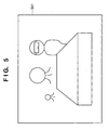
- Reference numeral 107 denotes the aforementioned HMD which displays the subjective viewpoint AR video generated by the AR game apparatus 104 on its display screen 501 shown in Fig. 5. Also, the HMD 107 senses the subjective viewpoint actually sensed video viewed from the subjective viewpoint of the player 101. The sensed video is sent to the AR game apparatus 104 via a cable shown in Fig. 1.
- Reference numeral 201 denotes a game state manager incorporated in the AR game apparatus 104.
- the game state manager 201 manages the state of the AR game (information that pertains to rendering of the virtual objects 102, the score of the player 101, AR game round count, and the like).
- the information that pertains to rendering of the virtual objects 102 includes information of the outer appearance of each virtual object 102, and information of the position/posture of each virtual object 102 in the world coordinate system.
- the information of the outer appearance of each virtual object 102 is information that pertains to polygons which build the virtual object 102, i.e., the number of polygons, the coordinate values of polygons, the colors of polygons, and the like.
- the information of the outer appearance of each virtual object 102 includes a texture size, texture file name, and the like.
- Reference numeral 204 denotes a camera parameter measurement/management unit which measures/manages camera parameters as parameters of the HMD 107 and camera 103.
- the camera parameters to be managed by the camera parameter measurement/management unit 204 includes viewpoint position/posture information as external parameters, and information of the field angle, focal length, distortion, and the like as internal parameters.
- the camera parameter measurement/management unit 204 stores the internal parameters of the HMD 107 as known information.
- the unit 204 measures the external parameters (information of the viewpoint position and posture) of the HMD 107, and manages the camera parameters of the HMD 107.
- the camera parameter measurement/management unit 204 manages camera parameters of the camera 103 as known information.
- Reference numeral 202 denotes an objective viewpoint video generator built in the AR game apparatus 104.
- the objective viewpoint video generator 202 generates objective viewpoint virtual videos on the basis of the information that pertains to rendering of the virtual objects 102, which is input from the game state manager 201.
- Reference numeral 203 denotes an objective viewpoint video composition unit built in the AR game apparatus 104, which generates an objective viewpoint AR video by compositing objective viewpoint virtual videos generated by the objective viewpoint video generator 202, and an objective viewpoint actually sensed video input from the camera 103.
- the game state manager 201 updates the information that pertains to rendering of the virtual objects 102 as needed, and outputs the updated information to a subjective viewpoint video generator 212.
- the subjective viewpoint video generator 212 generates videos of the virtual objects 102 (subjective viewpoint virtual video) viewed from the viewpoint position/posture of the HMD107, on the basis of the information that pertains to rendering of the virtual objects 102, which is input from the game state manager 201, and the camera parameters of the HMD 107, which are input from the camera parameter measurement/management unit 204.
- the generated subjective viewpoint virtual video is output to a subjective viewpoint video composition unit 213.
- the subjective viewpoint video composition unit 213 receives from the HMD 107 the subjective viewpoint actually sensed video that the player 101 watches via the HMD 107.
- the subjective viewpoint video composition unit 213 generates a subjective viewpoint AR video as a composite video of this subjective viewpoint actually sensed video, and the subjective viewpoint virtual videos input from the subjective viewpoint video generator 212, and outputs that subjective viewpoint AR video to the HMD 107.
- the subjective viewpoint AR video is displayed on the display screen 501 of the HMD 107, and the player 101 plays the AR game while reviewing this subjective viewpoint AR video.
- the game state manager 201 updates the information that pertains to rendering of the virtual objects 102 as needed, and outputs the updated information to the objective viewpoint video generator 202.
- the generated objective viewpoint virtual video is output to the objective viewpoint video composition unit 203.
- the objective viewpoint video composition unit 203 receives an objective viewpoint actually sensed video from the camera 103.
- the objective viewpoint video composition unit 203 generates an objective viewpoint AR video as a composite video of this objective viewpoint actually sensed video, and the objective viewpoint virtual videos input from the objective viewpoint video generator 202, and outputs the objective viewpoint AR video to the display 106.
- This objective viewpoint AR video is displayed on the display 106, and the watcher can see the overall view of the AR game by reviewing this objective viewpoint AR video and can recognize the current situation of the AR game.
- the image coordinate values of the vertices of the polygons that build each virtual object 102 viewed from each viewpoint can be computed using the coordinate conversion matrix Ml or M2 from the object coordinate system into the image coordinate system.
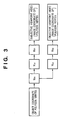
- the generation process of such coordinate conversion matrix will be explained below using the block diagram shown in Fig. 3.
- a coordinate conversion matrix Mm from the object coordinate system into a world coordinate system is computed on the basis of the information of the position/posture of each virtual object 102.
- coordinate conversion matrices Mcl and Mc2 from the world coordinate system into the corresponding camera coordinate systems are respectively computed on the basis of information of the positions/postures of respective viewpoints included in the camera parameters of the HMD 107 and camera 103.
- coordinate conversion matrices Mdl and Md2 for implementing perspective conversions from the corresponding camera coordinate systems into the image coordinate system are respectively computed on the basis of information such as the field angles, focal lengths, distortions, and the like included in the camera parameters of the HMD 107 and camera 103.
- the aforementioned coordinate conversion matrices are computed by the subjective viewpoint video generator 212 or objective viewpoint video generator 202.
- the present invention is not limit to these computations to make images. These computations are used, as factors that characterize subjective viewpoint and objective viewpoint.
- Fig. 7 shows the internal block diagram of the AR game apparatus 104.
- Reference numeral 701 denotes a CPU, which executes a program code loaded onto a RAM 703.
- the CPU 701 also has an area for temporarily saving data during execution of a program.
- Reference numeral 702 denotes a ROM which stores setups upon and after starting up the AR game apparatus 104, and a startup program code. Also, the ROM 702 stores character codes and the like used to display on the display screen 501 a score or the like output to the HMD 107 during the AR game.
- Reference numeral 703 denotes a RAM which stores a program code of the AR game loaded from a-floppy disk, CD-ROM, or the like as an external storage medium, polygon and texture data that build each virtual object 102, and the like.
- the game state manager 201 refers to and manages polygon (texture) data that build each virtual object 102, which are stored in the RAM 703.
- Reference numeral 704 denotes an interface (to be abbreviated as an I/F hereinafter), which is used to connect the AR game apparatus 104 to an external apparatus.
- the HMD 107, camera 103, and display 106 are all connected to the AR game apparatus 104 via this I/F 704.
- Reference numeral 705 denotes a console which comprises a keyboard and a pointing device such as a mouse or the like. This console 705 allows the user to input setup commands of the AR game apparatus 104, and those for peripheral devices connected to the AR game apparatus 104.
- Reference numeral 706 denotes a bus that connects the aforementioned units. Note that the game state manager 201, objective viewpoint video generator 202, objective viewpoint video composition unit 203, subjective viewpoint video generator 212, subjective viewpoint video composition unit 213, and camera parameter measurement/management unit 204 are connected to this bus 706, and are controlled via the bus 706 on the basis of the program code loaded onto the RAM 703, as described above.
- the game state manager 201 executes the program code loaded onto the RAM 703, the game state manager 201, objective viewpoint video generator 202, objective viewpoint video composition unit 203, subjective viewpoint video generator 212, subjective viewpoint video composition unit 213, and camera parameter measurement/management unit 204 execute the aforementioned processes, and output the subjective and objective viewpoint AR videos to the HMD 107 and display 106, respectively.
- the flow chart of this program code is shown in Fig. 8, and will be described below.
- step S801 the camera parameter measurement/management unit 204 updates the information of the viewpoint position/posture of the HMD 107.
- step S802 the game state manager 201 updates the game state (information that pertains to rendering of the virtual objects 102).
- step S803 the objective and subjective viewpoint video generators 202 and 212 respectively generate objective and subjective viewpoint videos.
- step S804 the objective and subjective viewpoint video composition units 203 and 213 respectively receive actually sensed videos sensed by the HMD 107 and 103.
- step S805 the objective and subjective viewpoint video composition units 203 and 213 respectively generate objective and subjective viewpoint AR videos.
- step S806 the objective and subjective viewpoint video composition units 203 and 213 respectively output the objective and subjective viewpoint AR videos to the display 106 and HMD 107.
- an objective viewpoint AR video can be presented to a third party other than the player 101 in the AR game using the video see-through HMD 107.
- the HMD 107 is of video see-through type. However, if the HMD 107 is of optical see-through type, the player 101 can still play the AR game.
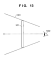
- Fig. 13 shows an optical see-through HMD 1301. Note that Fig. 13 schematically illustrates the HMD 1301, and the present invention is not limited to the size and shape shown in Fig. 13.
- Reference numeral 1301 denotes an optical see-through HMD; and 1302, the eye of the player 101.
- Fig. 14 is a block diagram showing the flow of processes of this embodiment.
- a video output from the AR game apparatus 104 to the HMD 1301 is a subjective viewpoint virtual video alone, as described above.
- the HMD 1301 and subjective viewpoint video generator 212 are electrically connected via a cable, and a subjective viewpoint virtual video which is generated by the subjective viewpoint video generator 212 on the basis of the position and posture of the HMD 1301 is sent from the subjective viewpoint video generator 212 to the HMD 1301.
- this embodiment has no subjective viewpoint video composition unit 213 in the first embodiment.
- the internal block diagram of the AR game apparatus 104 in this embodiment is substantially the same as that shown in Fig. 7, except that the objective viewpoint video composition unit 213 is removed from the arrangement shown in Fig. 7.
- steps S804, S805, and S806 in Fig. 8 are rewritten as follows. More specifically, upon generating a subjective viewpoint AR video (only videos of the virtual objects 102 based on the position and posture of the HMD 1301 in this embodiment) to be displayed on the HMD 1301, steps S804 and S805 are skipped. That is, in step S804 the objective viewpoint video composition unit 203 receives an actually sensed video sensed by the camera 103. In step S805, the objective viewpoint video composition unit 203 generates an objective viewpoint AR video. In step S806, the objective viewpoint video composition unit 203 outputs the objective viewpoint AR video to the display 106, and the subjective viewpoint video generator 212 outputs a subjective viewpoint virtual video to the HMD 1301.
- the flow chart obtained by modifying the contents of Fig. 8 as described above is that in this embodiment, and this embodiment is controlled by a program code according to this modified flow chart.
- an objective viewpoint AR video can be presented to a third party other than the player 101 in the AR game using the optical see-through HMD 1301.
- the camera parameters of the camera 103 are fixed. That is, an objective viewpoint AR video is generated based on the camera parameters of the camera 103 which is fixed in position.
- the camera parameter data of the camera 103 are stored as permanent values in the RAM 703 of the AR game apparatus 104.
- this embodiment uses a video see-through HMD as in the first embodiment.
- the HMD that can be used in this embodiment is not limited to the video see-through type, but an optical see-through HMD may be used, as can be seen from the description of the second embodiment and this embodiment.
- a measurement means as a means for measuring the position, posture, and zooming ratio of the camera 103 must be added to the first embodiment.
- Fig. 4 is a block diagram showing the flow of processes in this embodiment. The flow of processes in this embodiment will be described below using Fig. 4.
- the camera parameter measurement/management unit 204 measures and manages the camera parameters of the HMD 107, and holds some internal parameters of the camera 103 as known information. Unlike in the first embodiment, in this embodiment the camera parameter measurement/management unit 204 controls a sensor (not shown) attached to the camera 103 to measure the position, posture, and zooming ratio of the camera 103.
- the camera parameter measurement/management unit 204 measures the position, posture, and zooming ratio of the camera 103.
- the measurement result data (the position, posture, and zooming ratio data of the camera 103) by the camera parameter measurement/management unit 204, and the known internal parameters are output to the objective viewpoint video generator 202.
- the objective viewpoint video generator 202 generates an objective viewpoint virtual video on the basis of the input camera parameters of the camera 103 in the same manner as in the process in the first embodiment. Other processes are the same as those in the first embodiment.
- a control program code of the interface that changes the position, posture, and zooming ratio of the camera 103, and a control program code of the camera parameter measurement/managementunit 204 are stored in the RAM 703 of the AR game apparatus 104.
- the flow chart of this embodiment is the same as that shown in Fig. 8. However, in this embodiment the camera parameter measurement/management unit 204 updates the information of the viewpoint position and posture of the HMD 107 and the information of the viewpoint position, posture, and the zooming ratio of the camera 103 in step S801.
- Internal parameter zooming ratio
- position and posture may be variable.
- an objective viewpoint AR video can be generated based on data from the camera whose position and posture change.
- only one camera is set.
- objective viewpoint AR videos from a plurality of positions and postures can be displayed on the display 106.
- Fig. 9 shows a camera system in this embodiment.
- the camera system will be explained below using Fig. 9. Note that this embodiment sets three cameras.
- Reference numerals 901a, 901b, and 901c denote cameras (cameras 901a, 901b, and 901c), the camera parameters (positions, postures, field angles, and the like) of which are fixed.
- the functions of these cameras are the same as those in the first and second embodiments.
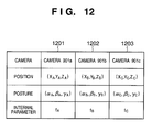
- the camera parameters of these three cameras are set, as shown in Fig. 12, and these three sets of data are stored in the RAM 703 of the AR game apparatus 104 and are managed by the camera parameter measurement/management unit 204.
- reference numerals 1201, 1202, and 1203 in Fig. 12 denote (selection information) tags corresponding to the cameras 901a, 901b, and 901c, which are used to select the camera to be used.
- Reference numeral 902 denotes a camera switching device, which has a function of a switcher that sends only a signal (actually sensed video of a real space sensed by the selected camera) from the camera selected by a selector 903 to the video composition unit 203 via the switching device 902.
- Reference numeral 903 denotes a selector which has the aforementioned function, and has three buttons (buttons A, B, and C) corresponding to the three cameras. When the user selectively presses one of these buttons, he or she can select the camera to be used.
- the selector 903 outputs selection information indicating the camera selected to the switching device 902 and camera parameter measurement/management unit 204. Note that the cameras 901a, 901b, and 901c are respectively selected by pressing buttons A, B, and C in Fig. 9 as the camera to be used.
- the camera parameter measurement/management unit 204 selects the tag (one of the tags 1201, 1202, and 1203) of the camera mentioned above in accordance with the camera selection information input from the selector 903, and outputs the camera parameters of the selected camera to the objective viewpoint video generator 202. For example, when the camera 901b is used, the camera parameters of the camera 901b held by the tag 1202 are output to the objective viewpoint video generator 202 upon depression of button B.
- Fig. 10 is a flow chart showing the process of this embodiment.
- step S1001 It is checked in step S1001 if one of the buttons of the selector 903 has been pressed. Note that this process is repeated until one of the buttons is pressed.
- step S1002 the button pressed is determined. Assuming that button B has been pressed, the flow advances from step S1003 to step S1006.
- steps S1005, S1006, and S1007 an actually sensed video sensed by the camera corresponding to the pressed button is sent to the objective viewpoint video composition unit 203 via the switching device 902. Also, the selection information of the camera corresponding to the pressed button is sent to the camera parameter measurement/management unit 204.
- a program code according to the aforementioned flow chart is stored in the internal memory (not shown) of the switching device 902.
- Camera switching may be automatically performed in accordance with the progress of a game.
- the selector 903 is omitted, and the game state manager 201 outputs camera selection information to the camera switching device 902 and the camera parameter measurement/management unit 204.
- Camera switching can employ a method of switching cameras every predetermined time interval or a method of switching cameras in accordance with the progress of a scenario by presetting a camera having an appropriate camera angle every time the scenario progresses.
- the camera parameters of the three cameras are fixed.
- the aforementioned arrangement of the apparatus, augmented reality presentation method, and program code can be applied.
- such application can be implemented by connecting the camera system of this embodiment to the AR game apparatus 104 in place of the camera 103 in the third embodiment.
- a plurality of objective viewpoint AR videos sensed by a plurality of cameras can be displayed on the display 106.
- an objective viewpoint AR video is presented to a third party other than the player via the display 106 by outputting it to the display 106.
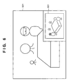
- the objective viewpoint AR video may be presented to the player 101. That is, a display area 601 shown in Fig. 6 is assured on the display screen 501 of the HMD (which can be of either video or optical see-through type) that the player 101 wears, and the objective viewpoint AR video is displayed there.
- a video displayed on this display screen 501 will be referred to as an augmented video hereinafter.
- a program code for setting the display area 601 on the display screen 501, and writing an objective viewpoint AR video on that display area 601 is stored in the RAM 703 of the AR game apparatus 104 in addition to the program code according to the flow chart shown in Fig. 8.
- the augmented video can be displayed on the display screen 501.
- Fig. 11 is a flow chart of the program code for writing the objective viewpoint AR video on the display area 601 mentioned above.
- step S1101 It is checked in step S1101 if the display area 601 is assured. Selection as to whether or not the display area 601 is assured can be implemented by providing this selection switch to an operation device (not shown) used when the player 101 plays the AR game. Or such selection can be implemented by inputting a command indicating whether or not the display area 601 is assured from the console 705.
- step S1102 the display position of the display area 601 is input.
- the display position is input from the console 705.
- the player 101 may input the display position using the aforementioned operation device.
- step S1103 the size of the display area 601 is input.
- the size is input from the console 705.
- the player 101 may input the size using the aforementioned operation device.
- step S1104 the display area 601, the setups of which have been determined in steps S1102 and S1103, is assured on the display screen 501.
- step S1105 the objective viewpoint AR video generated by the objective viewpoint video composition unit 203 is rendered on the display area 601. As a consequence, the augmented video can be generated.
- this augmented video may be output to the display 106.
- Selection of whether the display area 601 is set and the display position and size of the display area 601 may be automatically set/changed not by the player but in accordance with the progress of the game.
- the game state manager 201 determines these parameters.
- the display area 601 may be the entire area of the display screen 501.
- both the subjective and objective viewpoint AR videos can be presented to the player.
- a plurality of players 101 may join the AR game.
- subjective viewpoint AR videos from individual subjective viewpoints must be provided to the individual players.
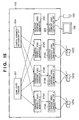
- Fig. 15 shows the internal arrangement of the AR game apparatus for providing subjective viewpoint AR videos from the players' subjective viewpoints to the individual players.
- the camera 103 is fixed in position, and the processes that pertain to the camera 103 and display are the same as those in the first embodiment.
- Fig. 15 shows the internal arrangement for three players.
- the AR game apparatus 104 comprises HMDs 107A, 107B, and 107C, subjective viewpoint video composition units 213A, 213B, and 213C, and subjective viewpoint video generators 212A, 212B, and 212C in correspondence with three players a, b, and c.
- Three players a, b, and c respectively wear the HMDs 107A, 107B, and 107C.
- This embodiment uses a video see-through HMD, but an optical see-through HMD may be used. In this case, the subjective viewpoint video composition units for the three HMDs can be omitted.
- the HMDs, subjective viewpoint video generators, and subjective viewpoint video composition units execute the same processes as those described in the first embodiment, and subjective viewpoint AR videos generated for the individual players are output to the HMDs 107A, 107B, and 107C that the players wear.
- subjective viewpoint AR videos can be provided to a plurality of players.
- a plurality of cameras 103 are set, but only one display 106 for displaying an objective viewpoint AR video is used.
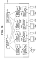
- the number of displays 106 is not limited to one, but a plurality of displays 106 may be used. That is, when objective viewpoint AR videos from the respective cameras 103 are separately displayed on a plurality of displays 106, the objective viewpoint AR videos from all the cameras 103 can be presented to a third party other than the player 101 using a plurality of displays 106.
- Fig. 16 shows the internal arrangement of the AR game apparatus 104 for displaying objective viewpoint AR videos from a plurality of cameras 103 on a plurality of displays 106.
- the AR game apparatus 104 comprises objective viewpoint video generators 202A, 202B, and 202C, and objective viewpoint video composition units 203A, 203B, and 203C corresponding to the displays 106A, 106B, and 106C so as to generate objective viewpoint AR videos corresponding to the displays 106A, 106B, and 106C.
- the cameras, objective viewpoint video generators, and objective viewpoint video composition units execute the same processes as those in the first embodiment, and objective viewpoint AR videos from the cameras 103A to 103C are displayed on the displays 106A to 106C corresponding to these cameras 103A to 103C.
- all objective viewpoint AR videos from a plurality of cameras 103 can be presented to a third party other than the player 101 using a plurality of displays 106.
- An apparatus that offers an AR video to the player 101 may be other than the game apparatus. That is, an AR apparatus which has substantially the same internal arrangement as that of the AR game apparatus 104 and stores a program code for implementing shopping in an AR space in place of a game program code may be used in place of the AR game apparatus 104. As a result, the player 101 can browse among presented products in shopping by observing a subjective viewpoint AR video from the AR apparatus, and that state is displayed on the display 106 as an objective viewpoint AR video.
- the camera parameters such as the position, posture, zoom ratio, and the like of the camera change
- they may be estimated from an actually sensed video input from the camera 103 in place of the sensor.
- the camera parameter measurement/management unit 204 receives an actually sensed video, and estimates camera parameters by a known method. In consideration of estimation errors, the camera parameters measured by the sensor and those estimated by the camera parameter measurement/management unit 204 may be averaged to determine camera parameters to be used finally.
- the generated objective viewpoint AR video can be not only displayed on the display 106 but also printed on a medium such as paper or a film.
- a print controller 301 printer control apparatus 301
- a printer 302 are added to the arrangement shown in each of the first to seventh embodiments.
- the 10th embodiment will be described with reference to Fig. 17 by exemplifying the arrangement of the first embodiment.
- an objective viewpoint AR video output from an objective viewpoint video composition unit 203 is output to the print controller 301 as well as the display 106.
- the print controller 301 stores the objective viewpoint AR video input at this time point and outputs the stored image to the printer 302 in accordance with a command input from a console 705.
- the printer 302 prints the input image on paper.
- the print controller 301 receives objective viewpoint AR videos respectively output from the objective viewpoint video composition units 203.
- the print controller 301 selects an objective viewpoint AR video having a specific viewpoint, stores the objective viewpoint AR video input at this time point, and outputs the stored image to the printer 302. It is possible to print the subjective viewpoint AR video of each embodiment described above in accordance with the same processing as described above.
- a subjective viewpoint video composition unit 213 outputs the subjective viewpoint AR video to an HMD 107 and at the same time to the print controller 301.
- the print controller 301 selects a viewpoint in accordance with a command input from the console 705 and stores the AR video viewed from the selected viewpoint.
- the print controller 301 determines a layout for printing a plurality of stored images on one paper sheet in accordance with a command input from the console 705 and outputs them to the printer 302.
- the command may be automatically input to the print controller 301 in accordance with the progress of a game without using the console 705.
- a game state manager 201 transmits a command to the print controller 301.
- the command may be transmitted at a fixed timing preset in accordance with the progress of the game or a dynamic timing corresponding to the progress of the game such that the distance between the player and a virtual object 102 becomes a predetermined interval or less.
- the camera 103 (or camera 901) can be located at an arbitrary position.
- the third party can easily grasp the state of the game when the camera is located at a position where the entire AR space can be observed from the bird-view position or a position where the upper half image (so-called bust shot) of the player can be sensed from the front.
- a video of the AR game viewed from the subjective viewpoint of the player can be generated, and, simultaneously, a video of the AR game viewed from an objective viewpoint to see the overall view of the game field or a video of the AR game viewed from a viewpoint the watcher wants can be generated.
- a game state manager (201) manages the state of an AR game (information that pertains to rendering of each virtual object (102), the score of a player (101), the AR game round count, and the like).
- An objective viewpoint video generator (202) generates a video of each virtual object (102) viewed from a camera (103).
- An objective viewpoint video composition unit (203) generates a composite video of the video of the virtual object (102) and an actually sensed video, and outputs it to a display (106).
- a subjective viewpoint video generator (212) generates a video of the virtual object (102) viewed from an HMD (107).
- a subjective viewpoint video composition unit (213) generates a composite video of the video of the virtual object (102) and an actually sensed video, and outputs it to the HMD (107).
Abstract
Description
- The present invention relates to an augmented reality presentation apparatus and method, which superimposes a virtual object on a real space, and a storage medium.
- More specifically, the present invention relates to an augmented reality presentation apparatus and method having a function of presenting a subjective augmented reality view for a-player and generating a video of the same augmented reality space observed from an objective viewpoint, and a storage medium.
- A conventional augmented reality (AR) game system is constructed by an AR game apparatus for controlling an AR game, a head-mounted display (to be abbreviated as an HMD hereinafter) which the player of the AR game wears, and a display for presenting a subjective viewpoint video of the player to a third party other than the player.
- The AR game apparatus controls the AR game, and generates information that pertains to rendering of a virtual object at the same time. The AR game apparatus generates a composite video as a video obtained by compositing a video of a virtual object generated using the information that pertains to rendering of the virtual object, and a video of a real space at the subjective viewpoint of the player, which is sensed by a camera attached to or built in the HMD.
- The composite video is displayed on the display screen of the HMD. The player plays the AR game while reviewing this composite video. In addition to the player, the video at the subjective viewpoint of the player as this composite video is presented to a third party who watches this AR game in addition to the player by displaying that video on a display prepared for a third party other than the player.
- Some TV programs use virtual studios in each of which a program stage set is built by virtual objects. In this virtual studio, a program video is generated by compositing an actually sensed video of characters of the program sensed by a set camera, and a video of the virtual studio seen at the position and posture of that camera.
- In the conventional AR (augmented reality) game system, a third party (watcher) other than the player can only watch a video generated for the player (mainly at the subjective viewpoint of the player). For this reason, the watcher cannot watch videos of the AR game at viewpoints other than the subjective viewpoint of the player, e.g., the overall view of the AR game viewed from the objective viewpoint, a video of the AR game at a desired viewpoint of the watcher, and the like and can neither recognize the overall status of the AR game nor watch the AR game from a desired viewpoint.
- Also, a program video using a virtual studio is generated at the objective viewpoint of a third party other than the characters of the program, but a video viewed from the subjective viewpoint of each character of the program cannot be generated.
- It is, therefore, an object of the present invention to generate a video of an AR game at the subjective viewpoint of the player and also generate the overall view of the AR game viewed from an objective viewpoint and a video of the AR game viewed from a desired viewpoint of the watcher.
- In order to achieve the above object, an augmented reality presentation apparatus described in
claim 1 as a preferred embodiment of the present invention comprises the following arrangement. - That is, augmented reality presentation means for superimposing the virtual object viewed from a player's viewpoint position in the real space viewed from said player's viewpoint position;
- the first video sensing means for sensing a video of the real space viewed from a first viewpoint position which differ from said player's viewpoint position;
- the first video generation means for generating a
video of the virtual object viewed from said first
viewpoint position;
and - the first video composition means for compositing an augmented reality video viewed from said first viewpoint position on the basis of said videos of the real space and the virtual object viewed from said first viewpoint position.
-
- As a result, a video that reviews an operating state of a virtual object by the player in the augmented reality space from the objective viewpoint position can be generated and presented to a third party other than the player.
- The augmented reality presentation apparatus as a preferred embodiment of the present invention further comprises the following feature described in claim 2.
- That is, said augmented reality presentation means further comprises:
- the second video sensing means for sensing a video of the real space viewed from said player's viewpoint position;
- the second video generation means for generating a video of the virtual object viewed from said player's viewpoint position;
- the second video composition means for
compositing an augmented reality video viewed from said
player's viewpoint position on the basis of said videos
of the real space and the virtual object viewed from
said player's viewpoint position;
and - the display means for displaying to the player the augmented reality video viewed from said player's viewpoint position.
-
- The augmented reality presentation apparatus as a preferred embodiment of the present invention further comprises the following feature described in claim 3.
- That is, said augmented reality presentation means further comprises:
- the second video generation means for generating
a video of the virtual object viewed from said player's
viewpoint position;
and - the display means for displaying to the player the video of the virtual object viewed from said player's viewpoint position on a display surface through which the player can visually see the real space.
-
- The augmented reality presentation apparatus as a preferred embodiment of the present invention further comprises the following feature described in
claim 4. - That is, information generation means for generating information that pertains to rendering of the virtual object, and
in that said first video generation means and said second video generation means generate videos of the virtual object using the information that pertains to rendering of the virtual object. - The augmented reality presentation apparatus as a preferred embodiment of the present invention further comprises the following feature described in claim 5.
- That is, said information generation means generates information of an outer appearance of the virtual object and information of a position/posture of the virtual object as the information that pertains to rendering of the virtual object.
- The augmented reality presentation apparatus as a preferred embodiment of the present invention further comprises the following feature described in claim 6.
- That is, parameters of said first video sensing means are known, and
said first video generation means generates the video of the virtual object viewed from said first viewpoint position in accordance with the known parameters. - The augmented reality presentation apparatus as a preferred embodiment of the present invention further comprises the following feature described in-claim 7.
- That is, some of parameters of said first video sensing means are variable,
- said apparatus further comprises measurement means for measuring changes of the parameters, and
- said first video generation means generates the video of the virtual object viewed from said first viewpoint position in accordance with the parameters measured by said measurement means.
-
- When the parameters of the objective viewpoint video sensing means, the objective viewpoint video generation means receives parameters from the measurement means, and generates an objective viewpoint video according to the received parameters.
- The augmented reality presentation apparatus as a preferred embodiment of the present invention further comprises the following feature described in claim 8.
- That is, the parameters of said first video sensing means measured by said measurement means include at least one of a viewpoint position/posture, and zoom ratio.
- The objective viewpoint video of a virtual object is generated in accordance with camera parameters (external parameters (viewpoint position/posture) and internal parameters (zoom ratio, aspect ratio, optical axis central position, distortion ratio)) of the objective viewpoint video sensing means. The camera parameters measured by the measurement means preferably include all parameters to be changed dynamically of those parameters.
- Other features and advantages of the present invention will be apparent from the following description taken in conjunction with the accompanying drawings, in which like reference characters designate the same or similar parts throughout the figures thereof.
- The accompanying drawings, which are incorporated in and constitute a part of the specification, illustrate embodiments of the invention and, together with the description, serve to explain the principles of the invention.
- Fig. 1 is a view showing the first embodiment;
- Fig. 2 is a block diagram showing the flow of processes of the first embodiment;
- Fig. 3 is a diagram showing the generation process of a coordinate conversion matrix used to convert the object coordinate position of a virtual object into an image coordinate position viewed from a given viewpoint;
- Fig. 4 is a block diagram showing the flow of processes of the third embodiment;
- Fig. 5 is a view showing a video presented to a player in the first to fourth embodiments;
- Fig. 6 is a view showing a video presented to a player in the fifth embodiment;
- Fig. 7 is a block diagram showing the internal arrangement of an AR game apparatus;
- Fig. 8 is a flow chart for generating a subjective viewpoint AR video and an objective viewpoint AR video;
- Fig. 9 is a diagram showing a camera system used in the fourth embodiment;
- Fig. 10 is a flow chart in the fourth embodiment;
- Fig. 11 is a flow chart in the fifth embodiment;
- Fig. 12 is a table showing camera parameters of a plurality of cameras in the fourth embodiment;
- Fig. 13 is a view for explaining an optical see-through HMD;
- Fig. 14 is a block diagram showing the flow of processes of the second embodiment;
- Fig. 15 is a block diagram showing the sixth embodiment; and
- Fig. 16 is a block diagram showing the seventh embodiment.
- Fig. 17 is a block diagram showing the flow of processes of the tenth embodiment.
-
- Preferred embodiments of the present invention will now be described in detail in accordance with the accompanying drawings.
- As one preferred embodiment of the present invention, this embodiment will explain an augmented reality presentation apparatus and method, which present a state in which a player is playing an AR (augmented reality) game in an AR space to a third party (to be referred to as a watcher hereinafter) other than the player.
- Fig. 1 shows this embodiment.
-
Reference numeral 101 denotes a player who is playing an AR (augmented reality) game, and wears a head-mounted display (to be abbreviated as an HMD hereinafter) 107 on his or her head. Note that theHMD 107 in this embodiment is of video see-through type which possesses video camera(s) inside or on it to capture the video(s) from the same viewpoint of the player's eye(s). Since the video see-through HMD is known to those who are skilled in the art, a detailed description thereof will be omitted. -
Reference numeral 102 denotes virtual objects as characters which appear in the AR game. Eachvirtual object 102 is a three-dimensional virtual object rendered by computer graphics. Thevirtual objects 102 are generated by a method to be described later by anAR game apparatus 104. Theplayer 101 can review a video obtained by superimposing thevirtual objects 102 on a real space (to be referred to as an AR video hereinafter) from his or her subjective viewpoint by wearing theHMD 107 on his or her head, and can consequently play the AR game. -
Reference numeral 103 denotes an objective viewpoint video sensing camera (to be simply referred to as a camera hereinafter) for sensing a state in which theplayer 101 is playing the AR game. In this embodiment, thiscamera 103 is fixed at a predetermined position and posture. A video sensed by the camera 103 (to be referred to as an objective viewpoint actually sensed video) is sent to theAR game apparatus 104 via a cable shown in Fig. 1. Note that the sensed video is an actually sensed video, which does not include any images of thevirtual objects 102. -
Reference numeral 104 denotes an AR game apparatus which controls the AR game, generates the videos of thevirtual objects 102, and generates an AR video to be output to theHMD 107 and adisplay 106. Note that a video which theAR game apparatus 104 outputs to theHMD 107 is an AR video (to be referred to as a subjective viewpoint AR video hereinafter) obtained by compositing an actually sensed video of the real space (to be referred to as a subjective viewpoint actually sensed video hereinafter) input from theHMD 107, and videos of thevirtual objects 102 viewed from the subjective viewpoint (to be referred to as subjective viewpoint virtual videos hereinafter). On the other hand, a video that theAR game apparatus 104 outputs to thedisplay 106 is an AR video (to be referred to as an objective viewpoint AR video hereinafter) obtained by compositing videos of thevirtual objects 102 viewed from the objective viewpoint (to be referred to as objective viewpoint virtual videos hereinafter), and the objective viewpoint actually sensed video sensed by thecamera 103. -
Reference numeral 105 denotes a table as a real object used as a stage in the AR game. -
Reference numeral 106 denotes a display which displays the objective viewpoint AR video generated by theAR game apparatus 104 to present the playing state of the AR game by theplayer 101 to a third party other than theplayer 101, as described above. -
Reference numeral 107 denotes the aforementioned HMD which displays the subjective viewpoint AR video generated by theAR game apparatus 104 on itsdisplay screen 501 shown in Fig. 5. Also, theHMD 107 senses the subjective viewpoint actually sensed video viewed from the subjective viewpoint of theplayer 101. The sensed video is sent to theAR game apparatus 104 via a cable shown in Fig. 1. - The flow of processes until the
AR game apparatus 104 displays the subjective and objective AR videos respectively on theHMD 107 and display 106 based on the aforementioned arrangement will be explained below using Fig. 2 that shows the flow of such processes. -
Reference numeral 201 denotes a game state manager incorporated in theAR game apparatus 104. Thegame state manager 201 manages the state of the AR game (information that pertains to rendering of thevirtual objects 102, the score of theplayer 101, AR game round count, and the like). Note that the information that pertains to rendering of thevirtual objects 102 includes information of the outer appearance of eachvirtual object 102, and information of the position/posture of eachvirtual object 102 in the world coordinate system. - The information of the outer appearance of each
virtual object 102 is information that pertains to polygons which build thevirtual object 102, i.e., the number of polygons, the coordinate values of polygons, the colors of polygons, and the like. When eachvirtual object 102 has undergone texture mapping, the information of the outer appearance of eachvirtual object 102 includes a texture size, texture file name, and the like. -
Reference numeral 204 denotes a camera parameter measurement/management unit which measures/manages camera parameters as parameters of theHMD 107 andcamera 103. The camera parameters to be managed by the camera parameter measurement/management unit 204 includes viewpoint position/posture information as external parameters, and information of the field angle, focal length, distortion, and the like as internal parameters. The camera parameter measurement/management unit 204 stores the internal parameters of theHMD 107 as known information. At the same time, theunit 204 measures the external parameters (information of the viewpoint position and posture) of theHMD 107, and manages the camera parameters of theHMD 107. Furthermore, the camera parameter measurement/management unit 204 manages camera parameters of thecamera 103 as known information. -
Reference numeral 202 denotes an objective viewpoint video generator built in theAR game apparatus 104. The objectiveviewpoint video generator 202 generates objective viewpoint virtual videos on the basis of the information that pertains to rendering of thevirtual objects 102, which is input from thegame state manager 201. -
Reference numeral 203 denotes an objective viewpoint video composition unit built in theAR game apparatus 104, which generates an objective viewpoint AR video by compositing objective viewpoint virtual videos generated by the objectiveviewpoint video generator 202, and an objective viewpoint actually sensed video input from thecamera 103. - Generation of the subjective viewpoint video will be explained below.
- The
game state manager 201 updates the information that pertains to rendering of thevirtual objects 102 as needed, and outputs the updated information to a subjectiveviewpoint video generator 212. The subjectiveviewpoint video generator 212 generates videos of the virtual objects 102 (subjective viewpoint virtual video) viewed from the viewpoint position/posture of the HMD107, on the basis of the information that pertains to rendering of thevirtual objects 102, which is input from thegame state manager 201, and the camera parameters of theHMD 107, which are input from the camera parameter measurement/management unit 204. - The generated subjective viewpoint virtual video is output to a subjective viewpoint
video composition unit 213. - The subjective viewpoint
video composition unit 213 receives from theHMD 107 the subjective viewpoint actually sensed video that theplayer 101 watches via theHMD 107. The subjective viewpointvideo composition unit 213 generates a subjective viewpoint AR video as a composite video of this subjective viewpoint actually sensed video, and the subjective viewpoint virtual videos input from the subjectiveviewpoint video generator 212, and outputs that subjective viewpoint AR video to theHMD 107. The subjective viewpoint AR video is displayed on thedisplay screen 501 of theHMD 107, and theplayer 101 plays the AR game while reviewing this subjective viewpoint AR video. - Generation of an objective viewpoint video will be explained below.
- The
game state manager 201 updates the information that pertains to rendering of thevirtual objects 102 as needed, and outputs the updated information to the objectiveviewpoint video generator 202. - Since generation of the videos of the
virtual objects 102 is implemented by the same processes as those in generation of the subjective viewpoint video, a detailed description thereof will be omitted. - The generated objective viewpoint virtual video is output to the objective viewpoint
video composition unit 203. - The objective viewpoint
video composition unit 203 receives an objective viewpoint actually sensed video from thecamera 103. The objective viewpointvideo composition unit 203 generates an objective viewpoint AR video as a composite video of this objective viewpoint actually sensed video, and the objective viewpoint virtual videos input from the objectiveviewpoint video generator 202, and outputs the objective viewpoint AR video to thedisplay 106. This objective viewpoint AR video is displayed on thedisplay 106, and the watcher can see the overall view of the AR game by reviewing this objective viewpoint AR video and can recognize the current situation of the AR game. - The image coordinate values of the vertices of the polygons that build each
virtual object 102 viewed from each viewpoint (HMD 107 or camera 103) can be computed using the coordinate conversion matrix Ml or M2 from the object coordinate system into the image coordinate system. The generation process of such coordinate conversion matrix will be explained below using the block diagram shown in Fig. 3. - A coordinate conversion matrix Mm from the object coordinate system into a world coordinate system is computed on the basis of the information of the position/posture of each
virtual object 102. Also, coordinate conversion matrices Mcl and Mc2 from the world coordinate system into the corresponding camera coordinate systems are respectively computed on the basis of information of the positions/postures of respective viewpoints included in the camera parameters of theHMD 107 andcamera 103. Furthermore, coordinate conversion matrices Mdl and Md2 for implementing perspective conversions from the corresponding camera coordinate systems into the image coordinate system are respectively computed on the basis of information such as the field angles, focal lengths, distortions, and the like included in the camera parameters of theHMD 107 andcamera 103. The aforementioned coordinate conversion matrices are computed by the subjectiveviewpoint video generator 212 or objectiveviewpoint video generator 202. - The conversion matrix Ml from the object coordinate system into the image coordinate system of the
HMD 107 is given by:camera 103 is given by:viewpoint video generator 212 or objectiveviewpoint video generator 202. - The present invention is not limit to these computations to make images. These computations are used, as factors that characterize subjective viewpoint and objective viewpoint.
- The internal arrangement and operation of the
AR game apparatus 104 will be explained below using Fig. 7 that shows the internal block diagram of theAR game apparatus 104. -
Reference numeral 701 denotes a CPU, which executes a program code loaded onto aRAM 703. TheCPU 701 also has an area for temporarily saving data during execution of a program. -
Reference numeral 702 denotes a ROM which stores setups upon and after starting up theAR game apparatus 104, and a startup program code. Also, theROM 702 stores character codes and the like used to display on the display screen 501 a score or the like output to theHMD 107 during the AR game. -
Reference numeral 703 denotes a RAM which stores a program code of the AR game loaded from a-floppy disk, CD-ROM, or the like as an external storage medium, polygon and texture data that build eachvirtual object 102, and the like. Note that thegame state manager 201 refers to and manages polygon (texture) data that build eachvirtual object 102, which are stored in theRAM 703. -
Reference numeral 704 denotes an interface (to be abbreviated as an I/F hereinafter), which is used to connect theAR game apparatus 104 to an external apparatus. TheHMD 107,camera 103, and display 106 are all connected to theAR game apparatus 104 via this I/F 704. -
Reference numeral 705 denotes a console which comprises a keyboard and a pointing device such as a mouse or the like. Thisconsole 705 allows the user to input setup commands of theAR game apparatus 104, and those for peripheral devices connected to theAR game apparatus 104. -
Reference numeral 706 denotes a bus that connects the aforementioned units. Note that thegame state manager 201, objectiveviewpoint video generator 202, objective viewpointvideo composition unit 203, subjectiveviewpoint video generator 212, subjective viewpointvideo composition unit 213, and camera parameter measurement/management unit 204 are connected to thisbus 706, and are controlled via thebus 706 on the basis of the program code loaded onto theRAM 703, as described above. - When the
CPU 701 executes the program code loaded onto theRAM 703, thegame state manager 201, objectiveviewpoint video generator 202, objective viewpointvideo composition unit 203, subjectiveviewpoint video generator 212, subjective viewpointvideo composition unit 213, and camera parameter measurement/management unit 204 execute the aforementioned processes, and output the subjective and objective viewpoint AR videos to theHMD 107 anddisplay 106, respectively. The flow chart of this program code is shown in Fig. 8, and will be described below. - In step S801, the camera parameter measurement/
management unit 204 updates the information of the viewpoint position/posture of theHMD 107. - In step S802, the
game state manager 201 updates the game state (information that pertains to rendering of the virtual objects 102). - In step S803, the objective and subjective
viewpoint video generators - In step S804, the objective and subjective viewpoint
video composition units HMD - In step S805, the objective and subjective viewpoint
video composition units - In step S806, the objective and subjective viewpoint
video composition units display 106 andHMD 107. - The aforementioned processes are repeated until the AR game ends.
- With the aforementioned arrangement of the apparatus, augmented reality presentation method, and program code, an objective viewpoint AR video can be presented to a third party other than the
player 101 in the AR game using the video see-throughHMD 107. - In the first embodiment, the
HMD 107 is of video see-through type. However, if theHMD 107 is of optical see-through type, theplayer 101 can still play the AR game. - Fig. 13 shows an optical see-through
HMD 1301. Note that Fig. 13 schematically illustrates theHMD 1301, and the present invention is not limited to the size and shape shown in Fig. 13. -
Reference numeral 1301 denotes an optical see-through HMD; and 1302, the eye of theplayer 101. - On the
display screen 501, only videos of the virtual objects 102 (subjective viewpoint virtual videos) are displayed. On the other hand, a video of a real space is seen behind thedisplay screen 501 when viewed from the position of theeye 1302. Hence, the player can review videos of thevirtual objects 102 and the real space seen behind thedisplay screen 501 when viewed from the position of theeye 1302 to overlap each other by observing thedisplay screen 501. - Fig. 14 is a block diagram showing the flow of processes of this embodiment.
- A video output from the
AR game apparatus 104 to theHMD 1301 is a subjective viewpoint virtual video alone, as described above. Hence, theHMD 1301 and subjectiveviewpoint video generator 212 are electrically connected via a cable, and a subjective viewpoint virtual video which is generated by the subjectiveviewpoint video generator 212 on the basis of the position and posture of theHMD 1301 is sent from the subjectiveviewpoint video generator 212 to theHMD 1301. Note that this embodiment has no subjective viewpointvideo composition unit 213 in the first embodiment. - Also, the method of generating an objective viewpoint AR video is the same as that which has been explained in the first embodiment.
- The internal block diagram of the
AR game apparatus 104 in this embodiment is substantially the same as that shown in Fig. 7, except that the objective viewpointvideo composition unit 213 is removed from the arrangement shown in Fig. 7. - In the flow chart of this embodiment, steps S804, S805, and S806 in Fig. 8 are rewritten as follows. More specifically, upon generating a subjective viewpoint AR video (only videos of the
virtual objects 102 based on the position and posture of theHMD 1301 in this embodiment) to be displayed on theHMD 1301, steps S804 and S805 are skipped. That is, in step S804 the objective viewpointvideo composition unit 203 receives an actually sensed video sensed by thecamera 103. In step S805, the objective viewpointvideo composition unit 203 generates an objective viewpoint AR video. In step S806, the objective viewpointvideo composition unit 203 outputs the objective viewpoint AR video to thedisplay 106, and the subjectiveviewpoint video generator 212 outputs a subjective viewpoint virtual video to theHMD 1301. - The flow chart obtained by modifying the contents of Fig. 8 as described above is that in this embodiment, and this embodiment is controlled by a program code according to this modified flow chart.
- With the aforementioned arrangement of the apparatus, augmented reality presentation method, and program code, an objective viewpoint AR video can be presented to a third party other than the
player 101 in the AR game using the optical see-throughHMD 1301. - In the first and second embodiments, the camera parameters of the
camera 103 are fixed. That is, an objective viewpoint AR video is generated based on the camera parameters of thecamera 103 which is fixed in position. The camera parameter data of thecamera 103 are stored as permanent values in theRAM 703 of theAR game apparatus 104. - A case will be examined below wherein the viewpoint position, posture, and zooming ratio of the
camera 103 are changed in real time to those that the player or a third party other than the player 101(watcher or operator) wants. That is, a case will be examined below wherein the camera parameters of thecamera 103 are changed in real time. Note that this embodiment uses a video see-through HMD as in the first embodiment. However, the HMD that can be used in this embodiment is not limited to the video see-through type, but an optical see-through HMD may be used, as can be seen from the description of the second embodiment and this embodiment. - When the position, posture, and zooming ratio of the
camera 103 are to be changed in real time, a measurement means as a means for measuring the position, posture, and zooming ratio of thecamera 103 must be added to the first embodiment. - Fig. 4 is a block diagram showing the flow of processes in this embodiment. The flow of processes in this embodiment will be described below using Fig. 4.
- Like in the first embodiment, in this embodiment the camera parameter measurement/
management unit 204 measures and manages the camera parameters of theHMD 107, and holds some internal parameters of thecamera 103 as known information. Unlike in the first embodiment, in this embodiment the camera parameter measurement/management unit 204 controls a sensor (not shown) attached to thecamera 103 to measure the position, posture, and zooming ratio of thecamera 103. - When the
player 101 has changed the position, posture, and zooming ratio of thecamera 103 via an interface (not shown), the camera parameter measurement/management unit 204 measures the position, posture, and zooming ratio of thecamera 103. The measurement result data (the position, posture, and zooming ratio data of the camera 103) by the camera parameter measurement/management unit 204, and the known internal parameters are output to the objectiveviewpoint video generator 202. The objectiveviewpoint video generator 202 generates an objective viewpoint virtual video on the basis of the input camera parameters of thecamera 103 in the same manner as in the process in the first embodiment. Other processes are the same as those in the first embodiment. - A control program code of the interface that changes the position, posture, and zooming ratio of the
camera 103, and a control program code of the camera parameter measurement/managementunit 204 are stored in theRAM 703 of theAR game apparatus 104. - The flow chart of this embodiment is the same as that shown in Fig. 8. However, in this embodiment the camera parameter measurement/
management unit 204 updates the information of the viewpoint position and posture of theHMD 107 and the information of the viewpoint position, posture, and the zooming ratio of thecamera 103 in step S801. - Internal parameter (zooming ratio) is fixed, position and posture may be variable. With the aforementioned arrangement of the apparatus, augmented reality presentation method, and program code, an objective viewpoint AR video can be generated based on data from the camera whose position and posture change.
- In the first to third embodiments, only one camera is set. Alternatively, when a plurality of cameras are set and the camera to be used is switched, objective viewpoint AR videos from a plurality of positions and postures can be displayed on the
display 106. - Fig. 9 shows a camera system in this embodiment. The camera system will be explained below using Fig. 9. Note that this embodiment sets three cameras.
-
Reference numerals cameras RAM 703 of theAR game apparatus 104 and are managed by the camera parameter measurement/management unit 204. - Note that
reference numerals cameras -
Reference numeral 902 denotes a camera switching device, which has a function of a switcher that sends only a signal (actually sensed video of a real space sensed by the selected camera) from the camera selected by aselector 903 to thevideo composition unit 203 via theswitching device 902. -
Reference numeral 903 denotes a selector which has the aforementioned function, and has three buttons (buttons A, B, and C) corresponding to the three cameras. When the user selectively presses one of these buttons, he or she can select the camera to be used. Theselector 903 outputs selection information indicating the camera selected to theswitching device 902 and camera parameter measurement/management unit 204. Note that thecameras - The camera parameter measurement/
management unit 204 selects the tag (one of thetags selector 903, and outputs the camera parameters of the selected camera to the objectiveviewpoint video generator 202. For example, when thecamera 901b is used, the camera parameters of thecamera 901b held by thetag 1202 are output to the objectiveviewpoint video generator 202 upon depression of button B. - Fig. 10 is a flow chart showing the process of this embodiment.
- It is checked in step S1001 if one of the buttons of the
selector 903 has been pressed. Note that this process is repeated until one of the buttons is pressed. - In steps S1002, S1003, and S1004, the button pressed is determined. Assuming that button B has been pressed, the flow advances from step S1003 to step S1006.
- In steps S1005, S1006, and S1007, an actually sensed video sensed by the camera corresponding to the pressed button is sent to the objective viewpoint
video composition unit 203 via theswitching device 902. Also, the selection information of the camera corresponding to the pressed button is sent to the camera parameter measurement/management unit 204. - A program code according to the aforementioned flow chart is stored in the internal memory (not shown) of the
switching device 902. - Camera switching may be automatically performed in accordance with the progress of a game. In this case, the
selector 903 is omitted, and thegame state manager 201 outputs camera selection information to thecamera switching device 902 and the camera parameter measurement/management unit 204. Camera switching can employ a method of switching cameras every predetermined time interval or a method of switching cameras in accordance with the progress of a scenario by presetting a camera having an appropriate camera angle every time the scenario progresses. - In this embodiment, the camera parameters of the three cameras are fixed. Alternatively, when the camera parameters of these cameras change in real time, the aforementioned arrangement of the apparatus, augmented reality presentation method, and program code can be applied. In this case, such application can be implemented by connecting the camera system of this embodiment to the
AR game apparatus 104 in place of thecamera 103 in the third embodiment. - With the aforementioned arrangement of the apparatus, augmented reality presentation method, and program code, a plurality of objective viewpoint AR videos sensed by a plurality of cameras can be displayed on the
display 106. - In the first to fourth embodiments, an objective viewpoint AR video is presented to a third party other than the player via the
display 106 by outputting it to thedisplay 106. Alternatively, the objective viewpoint AR video may be presented to theplayer 101. That is, adisplay area 601 shown in Fig. 6 is assured on thedisplay screen 501 of the HMD (which can be of either video or optical see-through type) that theplayer 101 wears, and the objective viewpoint AR video is displayed there. In Fig. 6, a video displayed on thisdisplay screen 501 will be referred to as an augmented video hereinafter. - In order to generate this augmented video, a program code for setting the
display area 601 on thedisplay screen 501, and writing an objective viewpoint AR video on thatdisplay area 601 is stored in theRAM 703 of theAR game apparatus 104 in addition to the program code according to the flow chart shown in Fig. 8. As a result, by executing this program code, the augmented video can be displayed on thedisplay screen 501. - Fig. 11 is a flow chart of the program code for writing the objective viewpoint AR video on the
display area 601 mentioned above. - It is checked in step S1101 if the
display area 601 is assured. Selection as to whether or not thedisplay area 601 is assured can be implemented by providing this selection switch to an operation device (not shown) used when theplayer 101 plays the AR game. Or such selection can be implemented by inputting a command indicating whether or not thedisplay area 601 is assured from theconsole 705. - In step S1102, the display position of the
display area 601 is input. The display position is input from theconsole 705. Alternatively, theplayer 101 may input the display position using the aforementioned operation device. - In step S1103, the size of the
display area 601 is input. The size is input from theconsole 705. Alternatively, theplayer 101 may input the size using the aforementioned operation device. - In step S1104, the
display area 601, the setups of which have been determined in steps S1102 and S1103, is assured on thedisplay screen 501. - In step S1105, the objective viewpoint AR video generated by the objective viewpoint
video composition unit 203 is rendered on thedisplay area 601. As a consequence, the augmented video can be generated. - Note that this augmented video may be output to the
display 106. - Selection of whether the
display area 601 is set and the display position and size of thedisplay area 601 may be automatically set/changed not by the player but in accordance with the progress of the game. In this case, thegame state manager 201 determines these parameters. - The
display area 601 may be the entire area of thedisplay screen 501. - With the aforementioned arrangement of the apparatus, augmented reality presentation method, and program code, both the subjective and objective viewpoint AR videos can be presented to the player.
- A plurality of
players 101 may join the AR game. In this case, subjective viewpoint AR videos from individual subjective viewpoints must be provided to the individual players. Fig. 15 shows the internal arrangement of the AR game apparatus for providing subjective viewpoint AR videos from the players' subjective viewpoints to the individual players. Note that thecamera 103 is fixed in position, and the processes that pertain to thecamera 103 and display are the same as those in the first embodiment. - Fig. 15 shows the internal arrangement for three players. Hence, the
AR game apparatus 104 comprisesHMDs video composition units viewpoint video generators HMDs - When the AR game starts, the HMDs, subjective viewpoint video generators, and subjective viewpoint video composition units execute the same processes as those described in the first embodiment, and subjective viewpoint AR videos generated for the individual players are output to the
HMDs - Note that the aforementioned arrangement of the apparatus and augmented reality presentation method are not limited to three players, as is obvious from the above description.
- With the aforementioned arrangement of the apparatus and augmented reality presentation method, subjective viewpoint AR videos can be provided to a plurality of players.
- In the fourth embodiment, a plurality of
cameras 103 are set, but only onedisplay 106 for displaying an objective viewpoint AR video is used. - However, the number of
displays 106 is not limited to one, but a plurality ofdisplays 106 may be used. That is, when objective viewpoint AR videos from therespective cameras 103 are separately displayed on a plurality ofdisplays 106, the objective viewpoint AR videos from all thecameras 103 can be presented to a third party other than theplayer 101 using a plurality ofdisplays 106. - In this embodiment, a case will be described below wherein a plurality of
cameras 103 and a plurality ofdisplays 106 are set. Fig. 16 shows the internal arrangement of theAR game apparatus 104 for displaying objective viewpoint AR videos from a plurality ofcameras 103 on a plurality ofdisplays 106. - In Fig. 16, three
cameras cameras AR game apparatus 104 comprises objectiveviewpoint video generators video composition units displays displays - When the AR game starts, the cameras, objective viewpoint video generators, and objective viewpoint video composition units execute the same processes as those in the first embodiment, and objective viewpoint AR videos from the
cameras 103A to 103C are displayed on thedisplays 106A to 106C corresponding to thesecameras 103A to 103C. - Note that the aforementioned arrangement of the apparatus and augmented reality presentation method are not limited to three
displays 106, as is obvious from the aforementioned description. - With the aforementioned arrangement of the apparatus and augmented reality presentation method, all objective viewpoint AR videos from a plurality of
cameras 103 can be presented to a third party other than theplayer 101 using a plurality ofdisplays 106. - An apparatus that offers an AR video to the
player 101 may be other than the game apparatus. That is, an AR apparatus which has substantially the same internal arrangement as that of theAR game apparatus 104 and stores a program code for implementing shopping in an AR space in place of a game program code may be used in place of theAR game apparatus 104. As a result, theplayer 101 can browse among presented products in shopping by observing a subjective viewpoint AR video from the AR apparatus, and that state is displayed on thedisplay 106 as an objective viewpoint AR video. - Note that these subjective and objective viewpoint AR videos can be generated in the same manner as in the above embodiments.
- When the camera parameters such as the position, posture, zoom ratio, and the like of the camera change, they may be estimated from an actually sensed video input from the
camera 103 in place of the sensor. In this case, the camera parameter measurement/management unit 204 receives an actually sensed video, and estimates camera parameters by a known method. In consideration of estimation errors, the camera parameters measured by the sensor and those estimated by the camera parameter measurement/management unit 204 may be averaged to determine camera parameters to be used finally. - The generated objective viewpoint AR video can be not only displayed on the
display 106 but also printed on a medium such as paper or a film. In this case, a print controller 301 (print control apparatus 301) and aprinter 302 are added to the arrangement shown in each of the first to seventh embodiments. The 10th embodiment will be described with reference to Fig. 17 by exemplifying the arrangement of the first embodiment. - In the 10th embodiment, an objective viewpoint AR video output from an objective viewpoint
video composition unit 203 is output to theprint controller 301 as well as thedisplay 106. Theprint controller 301 stores the objective viewpoint AR video input at this time point and outputs the stored image to theprinter 302 in accordance with a command input from aconsole 705. Theprinter 302 prints the input image on paper. - As in the seventh embodiment, when a plurality of objective viewpoint
video composition units 203 are used, theprint controller 301 receives objective viewpoint AR videos respectively output from the objective viewpointvideo composition units 203. In this case, in accordance with a command input from theconsole 705 theprint controller 301 selects an objective viewpoint AR video having a specific viewpoint, stores the objective viewpoint AR video input at this time point, and outputs the stored image to theprinter 302. It is possible to print the subjective viewpoint AR video of each embodiment described above in accordance with the same processing as described above. In this case, a subjective viewpointvideo composition unit 213 outputs the subjective viewpoint AR video to anHMD 107 and at the same time to theprint controller 301. - It is also possible to simultaneously print objective viewpoint AR videos viewed from a plurality of viewpoint positions, objective viewpoint AR videos viewed from the same viewpoint at different times, or subjective viewpoint AR videos of the respective players on one paper sheet. In this case, the
print controller 301 selects a viewpoint in accordance with a command input from theconsole 705 and stores the AR video viewed from the selected viewpoint. Theprint controller 301 determines a layout for printing a plurality of stored images on one paper sheet in accordance with a command input from theconsole 705 and outputs them to theprinter 302. - The command may be automatically input to the
print controller 301 in accordance with the progress of a game without using theconsole 705. In this case, agame state manager 201 transmits a command to theprint controller 301. The command may be transmitted at a fixed timing preset in accordance with the progress of the game or a dynamic timing corresponding to the progress of the game such that the distance between the player and avirtual object 102 becomes a predetermined interval or less. - The camera 103 (or camera 901) can be located at an arbitrary position. The third party can easily grasp the state of the game when the camera is located at a position where the entire AR space can be observed from the bird-view position or a position where the upper half image (so-called bust shot) of the player can be sensed from the front.
- As described above, according to the present invention, a video of the AR game viewed from the subjective viewpoint of the player can be generated, and, simultaneously, a video of the AR game viewed from an objective viewpoint to see the overall view of the game field or a video of the AR game viewed from a viewpoint the watcher wants can be generated.
- As many apparently widely different embodiments of the present invention can be made without departing from the spirit and scope thereof, it is to be understood that the invention is not limited to the specific embodiments thereof except as defined in the appended claims.
- A game state manager (201) manages the state of an AR game (information that pertains to rendering of each virtual object (102), the score of a player (101), the AR game round count, and the like). An objective viewpoint video generator (202) generates a video of each virtual object (102) viewed from a camera (103). An objective viewpoint video composition unit (203) generates a composite video of the video of the virtual object (102) and an actually sensed video, and outputs it to a display (106). A subjective viewpoint video generator (212) generates a video of the virtual object (102) viewed from an HMD (107). A subjective viewpoint video composition unit (213) generates a composite video of the video of the virtual object (102) and an actually sensed video, and outputs it to the HMD (107).
Claims (30)
- An augmented reality presentation apparatus for superimposing a virtual object in a real space, characterized by comprising:augmented reality presentation means for superimposing the virtual object viewed from a player's viewpoint position in the real space viewed from said player's viewpoint position;the first video sensing means for sensing a video of the real space viewed from a first viewpoint position which differ from said player's viewpoint position;the first video generation means for generating a video of the virtual object viewed from said first viewpoint position;
andthe first video composition means for compositing an augmented reality video viewed from said first viewpoint position on the basis of said videos of the real space and the virtual object viewed from said first viewpoint position. - The apparatus according to claim 1, characterized in that said augmented reality presentation means further comprises:the second video sensing means for sensing a video of the real space viewed from said player's viewpoint position;the second video generation means for generating a video of the virtual object viewed from said player's viewpoint position;the second video composition means for compositing an augmented reality video viewed from said player's viewpoint position on the basis of said videos of the real space and the virtual object viewed from said player's viewpoint position;
andthe display means for displaying to the player the augmented reality video viewed from said player's viewpoint position. - The apparatus according to claim 1, characterized in that said augmented reality presentation means further comprises:the second video generation means for generating a video of the virtual object viewed from said player's viewpoint position;
andthe display means for displaying to the player the video of the virtual object viewed from said player's viewpoint position on a display surface through which the player can visually see the real space. - The apparatus according to any one of claim 1 to 3, characterized by further comprising information generation means for generating information that pertains to rendering of the virtual object, and
in that said first video generation means and said second video generation means generate videos of the virtual object using the information that pertains to rendering of the virtual object. - The apparatus according to claim 4, characterized in that said information generation means generates information of an outer appearance of the virtual object and information of a position/posture of the virtual object as the information that pertains to rendering of the virtual object.
- The apparatus according to claim 1 or 4, characterized in that parameters of said first video sensing means are known, and
said first video generation means generates the video of the virtual object viewed from said first viewpoint position in accordance with the known parameters. - The apparatus according to claim 1 or 4, characterized in that some of parameters of said first video sensing means are variable,said apparatus further comprises measurement means for measuring changes of the parameters, andsaid first video generation means generates the video of the virtual object viewed from said first viewpoint position in accordance with the parameters measured by said measurement means.
- The apparatus according to claim 7, characterized in that the parameters of said first video sensing means measured by said measurement means include at least one of a viewpoint position/posture, and zoom ratio.
- The apparatus according to claim 1, characterized in that when a plurality of first video sensing means equivalent to said first video sensing means are present,said apparatus further comprises selection means for receiving a plurality of videos of the real space from said first viewpoint position from the plurality of first video sensing means, and outputting a video of the real space viewed from said first viewpoint position input from one selected first video sensing means to said first video composition means, andsaid first video composition means generates a video of the virtual object viewed from said first viewpoint position using parameters of the first video sensing means selected by said selection means.
- An augmented reality presentation method for superimposing a virtual object in a real space, characterized by comprising:augmented reality presentation step of superimposing the virtual object viewed from a player's viewpoint position in the real space viewed from said player's viewpoint position;the first video sensing step of sensing a video of the real space viewed from a first viewpoint position which differ from said player's viewpoint position;the first video generation step of generating a video of the virtual object viewed from said first viewpoint position;
andthe first video composition step of compositing an augmented reality video viewed from said first viewpoint position on the basis of said videos of the real space and the virtual object viewed from said first viewpoint position. - The method according to claim 10, characterized in that the augmented reality presentation step further comprises:the second video sensing step of sensing a video of the real space viewed from said player's viewpoint position;the second video generation step of generating a video of the virtual object viewed from said player's viewpoint position;the second video composition step of compositing an augmented reality video viewed from said player's viewpoint position on the basis of said videos of the real space and the virtual object viewed from said player's viewpoint position;
andthe display step of displaying to the player the augmented reality video viewed from said player's viewpoint position. - The method according to claim 10, characterized in that the augmented reality presentation step further comprises:the second video generation step of generating a video of the virtual object viewed from said player's viewpoint position;
andthe display step of displaying to the player the video of the virtual object viewed from said player's viewpoint position on a display surface through which the player can visually see the real space. - The method according to any one of claim 10 to 12, characterized by further comprising the information generation step of generating information that pertains to rendering of the virtual object,
and
in that in said first video generation step and said second video generation step, videos of the virtual object are generated using the information that pertains to rendering of the virtual object. - The method according to claim 13, characterized in that said information generation step includes the step of generating information of an outer appearance of the virtual object and information of a position/posture of the virtual object as the information that pertains to rendering of the virtual object.
- The method according to claim 10 or 13, characterized in that parameters of means for sensing said first viewpoint video are known, and
said first video generation step includes the step of generating the video of the virtual object viewed from said first viewpoint position in accordance with the known parameters. - The method according to claim 10 or 13,
characterized
in that some of parameters of means for sensing a video viewed from said first viewpoint position are variable,said method further comprises the measurement step of measuring changes of the parameters,
andsaid first video generation step includes the step of generating the video of the virtual object viewed from said first viewpoint position in accordance with the parameters measured in the measurement step. - The method according to claim 16, characterized in that the parameters of the means for sensing a video viewed from said first viewpoint position measured in the measurement step include at least one of a viewpoint position/posture, and zoom ratio.
- The method according to claim 10, characterized in that when a plurality of means for sensing a video viewed from said first viewpoint position are present,said method further comprises the selection step of receiving a plurality of videos of the real space viewed from a first viewpoint position from the plurality of means for sensing a video viewed from said first viewpoint position, and outputting the video of the real space viewed from a first viewpoint position input from one selected means for sensing a video of said first viewpoint position to means for compositing a first viewpoint video, andsaid first video composition step includes the step of generating a video of the virtual object viewed from said first viewpoint position using parameters of the means for sensing a video viewed from a first viewpoint position selected in the selection step.
- A storage medium storing a program code for superimposing a virtual object in a real space when said program code is loaded by a computer,
characterized by comprising:a program code of the augmented reality presentation step of superimposing the virtual object viewed from a player's viewpoint position in the real space viewed from said player' viewpoint position;a program code of the first video sensing step of sensing a video of the real space viewed from a first viewpoint position which differ from said player's viewpoint position;a program code of the first video generation step of generating a video of the virtual object viewed from said first viewpoint position;
anda program code of the first video composition step of compositing an augmented reality video viewed from said first viewpoint position on the basis of said videos of-the real space and the virtual object viewed from said first viewpoint position. - The medium according to claim 19, characterized in that the program code of the augmented reality presentation step further comprises:a program code of the second video sensing step of sensing a video of the real space viewed from said player's viewpoint position;a program code of the second video generation step of generating a video of the virtual object viewed from said player's viewpoint position;a program code of the second video composition step of compositing an augmented reality video viewed from said player's viewpoint position on the basis of said videos of the real space and the virtual object viewed from said player's viewpoint position;
anda program code of the display step of displaying to the player the augmented reality video viewed from said player's viewpoint position. - The medium according to claim 19, characterized in that the program code of the augmented reality presentation step further comprises:a program code of the second video generation step of generating a video of the virtual object viewed from said player's viewpoint position;
anda program code of the display step of displaying to the player the video of the virtual object viewed from said player's viewpoint position on a display surface through which the player can visually see the real space. - The medium according to any one of claim 19 to 21, characterized by further comprising a program code of the information generation step of generating information that pertains to rendering of the virtual object,
and
in that in the program codes of said first video generation step and said second video generation step, videos of the virtual object are generated using the information that pertains to rendering of the virtual object. - The medium according to claim 22, characterized in that the program code of said information generation step includes the step of generating information of an outer appearance of the virtual object and information of a position/posture of the virtual object as the information that pertains to rendering of the virtual object.
- The medium according to claim 19 or 22, characterized in that parameters of means for sensing said first viewpoint video are known, and
the program code of said first video generation step includes the step of generating the video of the virtual object viewed from said first viewpoint position in accordance with the known parameters. - The medium according to claim 19 or 22, characterized in that some of parameters of means for sensing a video viewed from said first viewpoint position are variable,the program code of said medium further comprises the measurement step of measuring changes of the parameters,
andthe program code of said first video generation step includes the step of generating the video of the virtual object viewed from said first viewpoint position in accordance with the parameters measured in the measurement step. - The medium according to claim 25, characterized in that the parameters of the means for sensing a video viewed from said first viewpoint position measured in the measurement step include at least one of a viewpoint position/posture, and zoom ratio.
- The medium according to claim 19, characterized in that when a plurality of means for sensing a video viewed from said first viewpoint position are present,said medium further comprises a program code of the selection step of receiving a plurality of videos of the real space viewed from a first viewpoint position from the plurality of means for sensing a video viewed from said first viewpoint position, and outputting the video of the real space viewed from a first viewpoint position input from one selected means for sensing a video of said first viewpoint position to means for compositing a first viewpoint video, andthe program code of said first video composition step includes the step of generating a video of the virtual object viewed from said first viewpoint position using parameters of the means for sensing a video viewed from a first viewpoint position selected in the selection step.
- The apparatus according to claim 1, characterized by further comprising printing means,in that said first video composition means outputs the augmented reality video to said printing means,said printing means grabs one frame of the received video and prints out to the paper as a still image.
- The method according to claim 10, characterized by further comprising printing step,in that in said first video composition step the augmented reality video is output to means for printing,in said printing step one frame of the received video is grabbed and printed out to the paper as a still image.
- The method according to claim 19, characterized by further comprising a program code of the printing step,in that in the program codes of said first video composition step the augmented reality video is output to means for printing,in the program codes of said printing step one frame of the received video is grabbed and printed out to the paper as a still image.
Applications Claiming Priority (2)
| Application Number | Priority Date | Filing Date | Title |
|---|---|---|---|
| JP2000004716A JP3363861B2 (en) | 2000-01-13 | 2000-01-13 | Mixed reality presentation device, mixed reality presentation method, and storage medium |
| JP2000004716 | 2000-01-13 |
Publications (2)
| Publication Number | Publication Date |
|---|---|
| EP1117074A2 true EP1117074A2 (en) | 2001-07-18 |
| EP1117074A3 EP1117074A3 (en) | 2004-01-07 |
Family
ID=18533473
Family Applications (1)
| Application Number | Title | Priority Date | Filing Date |
|---|---|---|---|
| EP00119769A Withdrawn EP1117074A3 (en) | 2000-01-13 | 2000-09-11 | Augmented reality presentation apparatus and method, and storage medium |
Country Status (3)
| Country | Link |
|---|---|
| US (1) | US7289130B1 (en) |
| EP (1) | EP1117074A3 (en) |
| JP (1) | JP3363861B2 (en) |
Cited By (35)
| Publication number | Priority date | Publication date | Assignee | Title |
|---|---|---|---|---|
| EP1241876A2 (en) | 2001-03-13 | 2002-09-18 | Canon Kabushiki Kaisha | Image processing apparatus, image processing method, and control program |
| WO2002073954A1 (en) * | 2001-03-13 | 2002-09-19 | Canon Kabushiki Kaisha | Image composition apparatus and method |
| EP1365358A2 (en) * | 2002-05-24 | 2003-11-26 | Olympus Optical Co., Ltd. | Information presentation system of visual field agreement type, and portable information terminal and server for use in the system |
| EP1372341A2 (en) * | 2002-05-24 | 2003-12-17 | Olympus Optical Co., Ltd. | Information display system and portable information terminal |
| WO2004072908A2 (en) * | 2003-02-17 | 2004-08-26 | Sony Computer Entertainment Inc. | Image generating method utilizing on-the-spot photograph and shape data |
| EP1503348A2 (en) * | 2003-07-30 | 2005-02-02 | Canon Kabushiki Kaisha | Image displaying method and apparatus for mixed reality space |
| EP1710002A1 (en) * | 2005-04-08 | 2006-10-11 | Canon Kabushiki Kaisha | Information processing method and apparatus |
| EP1837060A1 (en) * | 2006-03-21 | 2007-09-26 | In Fusio (S.A.) | Method for displaying interactive video content from a video stream in a display of a user device |
| EP1852828A2 (en) | 2006-05-02 | 2007-11-07 | Canon Kabushiki Kaisha | Information processing apparatus and control method thereof, image processing apparatus, computer program, and storage medium |
| CN101872241A (en) * | 2009-04-26 | 2010-10-27 | 艾利维公司 | Set up the method and system of the network game communal space |
| EP2243526A3 (en) * | 2009-04-26 | 2011-01-26 | Ailive Inc. | Method and system for controlling movements of objects in a videogame |
| EP2098271A3 (en) * | 2008-02-21 | 2011-04-06 | Palo Alto Research Center Incorporated | A location-aware mixed-reality gaming platform |
| US8139087B2 (en) * | 2005-07-01 | 2012-03-20 | Canon Kabushiki Kaisha | Image presentation system, image presentation method, program for causing computer to execute the method, and storage medium storing the program |
| WO2012066484A1 (en) * | 2010-11-16 | 2012-05-24 | Braun Gmbh | Virtual product demonstration |
| CN102859470A (en) * | 2011-03-15 | 2013-01-02 | 松下电器产业株式会社 | Object control device, object control method, object control program, and integrated circuit |
| US8378997B2 (en) | 2006-04-21 | 2013-02-19 | Canon Kabushiki Kaisha | Information processing method and device for presenting haptics received from a virtual object |
| US20140098130A1 (en) * | 2012-10-05 | 2014-04-10 | Elwha Llc | Systems and methods for sharing augmentation data |
| US9077647B2 (en) | 2012-10-05 | 2015-07-07 | Elwha Llc | Correlating user reactions with augmentations displayed through augmented views |
| US9111383B2 (en) | 2012-10-05 | 2015-08-18 | Elwha Llc | Systems and methods for obtaining and using augmentation data and for sharing usage data |
| US9141188B2 (en) | 2012-10-05 | 2015-09-22 | Elwha Llc | Presenting an augmented view in response to acquisition of data inferring user activity |
| US9639964B2 (en) | 2013-03-15 | 2017-05-02 | Elwha Llc | Dynamically preserving scene elements in augmented reality systems |
| US9671863B2 (en) | 2012-10-05 | 2017-06-06 | Elwha Llc | Correlating user reaction with at least an aspect associated with an augmentation of an augmented view |
| WO2017161281A1 (en) * | 2016-03-17 | 2017-09-21 | Sony Interactive Enteratainment Inc. | Spectating virtual reality (vr) environments associated with vr user interactivity |
| CN107408314A (en) * | 2015-01-20 | 2017-11-28 | 微软技术许可有限责任公司 | Mixed reality system |
| CN108159698A (en) * | 2017-12-29 | 2018-06-15 | 武汉艺术先生数码科技有限公司 | Indoor cool run game simulation system based on AR |
| CN108176051A (en) * | 2017-12-29 | 2018-06-19 | 武汉艺术先生数码科技有限公司 | Indoor cool run game simulation system |
| US10025486B2 (en) | 2013-03-15 | 2018-07-17 | Elwha Llc | Cross-reality select, drag, and drop for augmented reality systems |
| WO2018191312A1 (en) * | 2017-04-11 | 2018-10-18 | Dolby Laboratories Licensing Corporation | Layered augmented entertainment experiences |
| US10109075B2 (en) | 2013-03-15 | 2018-10-23 | Elwha Llc | Temporal element restoration in augmented reality systems |
| CN109069934A (en) * | 2016-03-18 | 2018-12-21 | 索尼互动娱乐股份有限公司 | Spectators' view tracking to the VR user in reality environment (VR) |
| CN109200586A (en) * | 2017-06-29 | 2019-01-15 | 深圳市掌网科技股份有限公司 | Game implementation method and device based on augmented reality |
| WO2019067480A1 (en) * | 2017-09-29 | 2019-04-04 | Sony Interactive Entertainment America Llc | Venue mapping for virtual reality spectating of electronic sports |
| US10269179B2 (en) | 2012-10-05 | 2019-04-23 | Elwha Llc | Displaying second augmentations that are based on registered first augmentations |
| US10463962B2 (en) | 2016-03-18 | 2019-11-05 | Sony Interactive Entertainment Inc. | Spectator view perspectives in VR environments |
| EP3404624B1 (en) * | 2016-01-15 | 2022-10-12 | Meleap Inc. | Image display system, image display system control method, image distribution system, and head-mounted display |
Families Citing this family (87)
| Publication number | Priority date | Publication date | Assignee | Title |
|---|---|---|---|---|
| DE50007901D1 (en) * | 1999-03-02 | 2004-10-28 | Siemens Ag | USE OF AUGMENTED REALITY BASIC TECHNOLOGIES FOR SITUATION-RELATED SUPPORT OF THE SPECIALIST BY DISTANT EXPERTS |
| WO2002073955A1 (en) * | 2001-03-13 | 2002-09-19 | Canon Kabushiki Kaisha | Image processing apparatus, image processing method, studio apparatus, storage medium, and program |
| US8035612B2 (en) | 2002-05-28 | 2011-10-11 | Intellectual Ventures Holding 67 Llc | Self-contained interactive video display system |
| US8300042B2 (en) * | 2001-06-05 | 2012-10-30 | Microsoft Corporation | Interactive video display system using strobed light |
| US20050122308A1 (en) * | 2002-05-28 | 2005-06-09 | Matthew Bell | Self-contained interactive video display system |
| US7710391B2 (en) * | 2002-05-28 | 2010-05-04 | Matthew Bell | Processing an image utilizing a spatially varying pattern |
| JP4065507B2 (en) * | 2002-07-31 | 2008-03-26 | キヤノン株式会社 | Information presentation apparatus and information processing method |
| US7427996B2 (en) | 2002-10-16 | 2008-09-23 | Canon Kabushiki Kaisha | Image processing apparatus and image processing method |
| JP4125085B2 (en) * | 2002-10-16 | 2008-07-23 | キヤノン株式会社 | Image processing apparatus and image processing method |
| JP4235522B2 (en) * | 2003-09-25 | 2009-03-11 | キヤノン株式会社 | Image processing apparatus, image processing method, and program |
| US7693702B1 (en) * | 2002-11-01 | 2010-04-06 | Lockheed Martin Corporation | Visualizing space systems modeling using augmented reality |
| AU2003301043A1 (en) * | 2002-12-13 | 2004-07-09 | Reactrix Systems | Interactive directed light/sound system |
| JP4027294B2 (en) * | 2003-09-26 | 2007-12-26 | 株式会社国際電気通信基礎技術研究所 | Moving object detection apparatus, moving object detection method, and moving object detection program |
| CN102034197A (en) | 2003-10-24 | 2011-04-27 | 瑞克楚斯系统公司 | Method and system for managing an interactive video display system |
| JP2005250748A (en) * | 2004-03-03 | 2005-09-15 | Nippon Hoso Kyokai <Nhk> | Video compositing apparatus, video compositing program and video compositing system |
| US8194002B2 (en) * | 2004-09-14 | 2012-06-05 | The Boeing Company | Situational awareness components of an enhanced vision system |
| US8585476B2 (en) | 2004-11-16 | 2013-11-19 | Jeffrey D Mullen | Location-based games and augmented reality systems |
| US7774275B2 (en) | 2005-02-28 | 2010-08-10 | Searete Llc | Payment options for virtual credit |
| US8096882B2 (en) | 2005-02-04 | 2012-01-17 | The Invention Science Fund I, Llc | Risk mitigation in a virtual world |
| US8512143B2 (en) | 2005-07-18 | 2013-08-20 | The Invention Science Fund I, Llc | Third party control over virtual world characters |
| US7937314B2 (en) | 2005-10-21 | 2011-05-03 | The Invention Science Fund I | Disposition of component virtual property rights |
| US8457991B2 (en) | 2005-02-04 | 2013-06-04 | The Invention Science Fund I, Llc | Virtual credit in simulated environments |
| US8556723B2 (en) | 2005-02-04 | 2013-10-15 | The Invention Science Fund I. LLC | Third party control over virtual world characters |
| US7720687B2 (en) * | 2005-10-03 | 2010-05-18 | The Invention Science Fund I, Llc | Virtual world property disposition after real-world occurrence |
| US7890419B2 (en) * | 2005-02-04 | 2011-02-15 | The Invention Science Fund I, Llc | Virtual credit in simulated environments |
| US8060829B2 (en) | 2005-04-15 | 2011-11-15 | The Invention Science Fund I, Llc | Participation profiles of virtual world players |
| US8473382B2 (en) | 2006-02-28 | 2013-06-25 | The Invention Science Fund I, Llc | Virtual collateral for real-world obligations |
| US8271365B2 (en) * | 2005-02-04 | 2012-09-18 | The Invention Science Fund I, Llc | Real-world profile data for making virtual world contacts |
| US7958047B2 (en) | 2005-02-04 | 2011-06-07 | The Invention Science Fund I | Virtual credit in simulated environments |
| US8566111B2 (en) | 2005-02-04 | 2013-10-22 | The Invention Science Fund I, Llc | Disposition of component virtual property rights |
| US9128519B1 (en) | 2005-04-15 | 2015-09-08 | Intellectual Ventures Holding 67 Llc | Method and system for state-based control of objects |
| US8081822B1 (en) | 2005-05-31 | 2011-12-20 | Intellectual Ventures Holding 67 Llc | System and method for sensing a feature of an object in an interactive video display |
| FR2889761A1 (en) * | 2005-08-09 | 2007-02-16 | Total Immersion Sa | SYSTEM FOR USER TO LOCATE A CAMERA FOR QUICKLY ADJUSTED INSERTION OF VIRTUAL IMAGE IMAGES IN VIDEO IMAGES OF CAMERA-CAPTURED ACTUAL ELEMENTS |
| US7920165B2 (en) * | 2005-09-26 | 2011-04-05 | Adderton Dennis M | Video training system |
| US8098277B1 (en) | 2005-12-02 | 2012-01-17 | Intellectual Ventures Holding 67 Llc | Systems and methods for communication between a reactive video system and a mobile communication device |
| JP4834424B2 (en) * | 2006-03-03 | 2011-12-14 | キヤノン株式会社 | Information processing apparatus, information processing method, and program |
| JP4847195B2 (en) * | 2006-04-21 | 2011-12-28 | キヤノン株式会社 | How to get color information from an image |
| JP4847203B2 (en) * | 2006-04-27 | 2011-12-28 | キヤノン株式会社 | Information processing method and information processing apparatus |
| JP4757115B2 (en) | 2006-06-28 | 2011-08-24 | キヤノン株式会社 | Image processing apparatus and image processing method |
| JP4883774B2 (en) * | 2006-08-07 | 2012-02-22 | キヤノン株式会社 | Information processing apparatus, control method therefor, and program |
| JP5067850B2 (en) * | 2007-08-02 | 2012-11-07 | キヤノン株式会社 | System, head-mounted display device, and control method thereof |
| US8230367B2 (en) | 2007-09-14 | 2012-07-24 | Intellectual Ventures Holding 67 Llc | Gesture-based user interactions with status indicators for acceptable inputs in volumetric zones |
| US8159682B2 (en) | 2007-11-12 | 2012-04-17 | Intellectual Ventures Holding 67 Llc | Lens system |
| US20110175903A1 (en) * | 2007-12-20 | 2011-07-21 | Quantum Medical Technology, Inc. | Systems for generating and displaying three-dimensional images and methods therefor |
| US8259163B2 (en) | 2008-03-07 | 2012-09-04 | Intellectual Ventures Holding 67 Llc | Display with built in 3D sensing |
| US8595218B2 (en) | 2008-06-12 | 2013-11-26 | Intellectual Ventures Holding 67 Llc | Interactive display management systems and methods |
| EP2374110A4 (en) * | 2008-12-19 | 2013-06-05 | Saab Ab | System and method for mixing a scene with a virtual scenario |
| US8970690B2 (en) * | 2009-02-13 | 2015-03-03 | Metaio Gmbh | Methods and systems for determining the pose of a camera with respect to at least one object of a real environment |
| US8379056B2 (en) * | 2009-02-27 | 2013-02-19 | Fraunhofer-Gesellschaft Zur Foerderung Der Angewandten Forschung E.V. | Device and method for providing a video signal of a virtual image |
| US20100306825A1 (en) | 2009-05-27 | 2010-12-02 | Lucid Ventures, Inc. | System and method for facilitating user interaction with a simulated object associated with a physical location |
| US20110065496A1 (en) * | 2009-09-11 | 2011-03-17 | Wms Gaming, Inc. | Augmented reality mechanism for wagering game systems |
| US8506377B2 (en) | 2010-09-30 | 2013-08-13 | Disney Enterprises, Inc. | Systems and methods to provide augmented reality for a board game |
| US8836771B2 (en) | 2011-04-26 | 2014-09-16 | Echostar Technologies L.L.C. | Apparatus, systems and methods for shared viewing experience using head mounted displays |
| US8854282B1 (en) * | 2011-09-06 | 2014-10-07 | Google Inc. | Measurement method |
| US9155964B2 (en) * | 2011-09-14 | 2015-10-13 | Steelseries Aps | Apparatus for adapting virtual gaming with real world information |
| JP5718197B2 (en) * | 2011-09-14 | 2015-05-13 | 株式会社バンダイナムコゲームス | Program and game device |
| US9182815B2 (en) * | 2011-12-07 | 2015-11-10 | Microsoft Technology Licensing, Llc | Making static printed content dynamic with virtual data |
| US9183807B2 (en) * | 2011-12-07 | 2015-11-10 | Microsoft Technology Licensing, Llc | Displaying virtual data as printed content |
| US9229231B2 (en) | 2011-12-07 | 2016-01-05 | Microsoft Technology Licensing, Llc | Updating printed content with personalized virtual data |
| US20130293580A1 (en) | 2012-05-01 | 2013-11-07 | Zambala Lllp | System and method for selecting targets in an augmented reality environment |
| US9165381B2 (en) | 2012-05-31 | 2015-10-20 | Microsoft Technology Licensing, Llc | Augmented books in a mixed reality environment |
| US20150213649A1 (en) * | 2012-07-27 | 2015-07-30 | Nec Solutions Innovators, Ltd. | Three-dimensional environment sharing system and three-dimensional environment sharing method |
| JP6143469B2 (en) * | 2013-01-17 | 2017-06-07 | キヤノン株式会社 | Information processing apparatus, information processing method, and program |
| US10363486B2 (en) | 2013-06-10 | 2019-07-30 | Pixel Press Technology, LLC | Smart video game board system and methods |
| US9579573B2 (en) * | 2013-06-10 | 2017-02-28 | Pixel Press Technology, LLC | Systems and methods for creating a playable video game from a three-dimensional model |
| US10955665B2 (en) * | 2013-06-18 | 2021-03-23 | Microsoft Technology Licensing, Llc | Concurrent optimal viewing of virtual objects |
| US9691181B2 (en) * | 2014-02-24 | 2017-06-27 | Sony Interactive Entertainment Inc. | Methods and systems for social sharing head mounted display (HMD) content with a second screen |
| JP6011567B2 (en) * | 2014-03-10 | 2016-10-19 | キヤノンマーケティングジャパン株式会社 | Information processing apparatus, control method thereof, and program |
| US10600245B1 (en) * | 2014-05-28 | 2020-03-24 | Lucasfilm Entertainment Company Ltd. | Navigating a virtual environment of a media content item |
| US20150362733A1 (en) * | 2014-06-13 | 2015-12-17 | Zambala Lllp | Wearable head-mounted display and camera system with multiple modes |
| US9779554B2 (en) * | 2015-04-10 | 2017-10-03 | Sony Interactive Entertainment Inc. | Filtering and parental control methods for restricting visual activity on a head mounted display |
| CN105107200B (en) * | 2015-08-14 | 2018-09-25 | 济南中景电子科技有限公司 | Face Changing system and method based on real-time deep body feeling interaction and augmented reality |
| JP6641122B2 (en) | 2015-08-27 | 2020-02-05 | キヤノン株式会社 | Display device, information processing device, and control method therefor |
| WO2017068824A1 (en) * | 2015-10-21 | 2017-04-27 | シャープ株式会社 | Image generation device, method for controlling image generation device, display system, image generation control program, and computer-readable recording medium |
| CN109478339A (en) * | 2016-07-29 | 2019-03-15 | 三菱电机株式会社 | Display device, display control unit and display control method |
| US10656704B2 (en) * | 2017-05-10 | 2020-05-19 | Universal City Studios Llc | Virtual reality mobile pod |
| JP2018198025A (en) * | 2017-05-25 | 2018-12-13 | 株式会社Five for | Image processing device, image processing device control method, and program |
| JP6799017B2 (en) * | 2017-12-18 | 2020-12-09 | ガンホー・オンライン・エンターテイメント株式会社 | Terminal devices, systems, programs and methods |
| JP6669783B2 (en) * | 2017-12-25 | 2020-03-18 | ガンホー・オンライン・エンターテイメント株式会社 | Terminal device, system, program and method |
| JP6857795B2 (en) | 2017-12-28 | 2021-04-14 | 株式会社コナミデジタルエンタテインメント | Information processing device, information processing device program, information processing system, and display method |
| JP6590324B2 (en) | 2017-12-28 | 2019-10-16 | 株式会社コナミデジタルエンタテインメント | Information processing apparatus, information processing apparatus program, information processing system, and display method |
| JP7364218B2 (en) | 2017-12-28 | 2023-10-18 | 株式会社コナミデジタルエンタテインメント | Information processing device, program for information processing device, information processing system, and display method |
| US11870972B2 (en) | 2018-10-02 | 2024-01-09 | Within Unlimited, Inc. | Methods, systems and devices supporting real-time shared virtual reality environment |
| JP6611145B1 (en) * | 2018-10-05 | 2019-11-27 | neten株式会社 | Third person view VR system and method of use thereof |
| JP6849709B2 (en) * | 2019-01-17 | 2021-03-24 | 株式会社カプコン | Game programs and game systems |
| JP2020204856A (en) * | 2019-06-17 | 2020-12-24 | 株式会社バンダイナムコアミューズメント | Image generation system and program |
| JP7029189B2 (en) * | 2020-03-06 | 2022-03-03 | 株式会社コナミデジタルエンタテインメント | Viewpoint confirmation system |
Citations (1)
| Publication number | Priority date | Publication date | Assignee | Title |
|---|---|---|---|---|
| US5850352A (en) * | 1995-03-31 | 1998-12-15 | The Regents Of The University Of California | Immersive video, including video hypermosaicing to generate from multiple video views of a scene a three-dimensional video mosaic from which diverse virtual video scene images are synthesized, including panoramic, scene interactive and stereoscopic images |
Family Cites Families (6)
| Publication number | Priority date | Publication date | Assignee | Title |
|---|---|---|---|---|
| EP0677187B1 (en) * | 1990-11-30 | 2002-09-18 | Sun Microsystems, Inc. | Improved method and apparatus for creating virtual worlds |
| US6317127B1 (en) * | 1996-10-16 | 2001-11-13 | Hughes Electronics Corporation | Multi-user real-time augmented reality system and method |
| US6522312B2 (en) * | 1997-09-01 | 2003-02-18 | Canon Kabushiki Kaisha | Apparatus for presenting mixed reality shared among operators |
| US6166744A (en) * | 1997-11-26 | 2000-12-26 | Pathfinder Systems, Inc. | System for combining virtual images with real-world scenes |
| RU2161871C2 (en) * | 1998-03-20 | 2001-01-10 | Латыпов Нурахмед Нурисламович | Method and device for producing video programs |
| JP3745117B2 (en) * | 1998-05-08 | 2006-02-15 | キヤノン株式会社 | Image processing apparatus and image processing method |
-
2000
- 2000-01-13 JP JP2000004716A patent/JP3363861B2/en not_active Expired - Lifetime
- 2000-09-08 US US09/658,463 patent/US7289130B1/en not_active Expired - Lifetime
- 2000-09-11 EP EP00119769A patent/EP1117074A3/en not_active Withdrawn
Patent Citations (1)
| Publication number | Priority date | Publication date | Assignee | Title |
|---|---|---|---|---|
| US5850352A (en) * | 1995-03-31 | 1998-12-15 | The Regents Of The University Of California | Immersive video, including video hypermosaicing to generate from multiple video views of a scene a three-dimensional video mosaic from which diverse virtual video scene images are synthesized, including panoramic, scene interactive and stereoscopic images |
Non-Patent Citations (2)
| Title |
|---|
| KANBARA M ET AL: "Real-time composition of stereo images for video see-through augmented reality" MULTIMEDIA COMPUTING AND SYSTEMS, 1999. IEEE INTERNATIONAL CONFERENCE ON FLORENCE, ITALY 7-11 JUNE 1999, LOS ALAMITOS, CA, USA,IEEE COMPUT. SOC, US, 7 June 1999 (1999-06-07), pages 213-219, XP010342853 ISBN: 0-7695-0253-9 * |
| OHSHIMA T ET AL: "ARHockey: a case study of collaborative augmented reality" VIRTUAL REALITY ANNUAL INTERNATIONAL SYMPOSIUM, 1998. PROCEEDINGS., IEEE 1998 ATLANTA, GA, USA 14-18 MARCH 1998, LOS ALAMITOS, CA, USA,IEEE COMPUT. SOC, US, 14 March 1998 (1998-03-14), pages 268-275, XP010268738 ISBN: 0-8186-8362-7 * |
Cited By (76)
| Publication number | Priority date | Publication date | Assignee | Title |
|---|---|---|---|---|
| US7038699B2 (en) | 2001-03-13 | 2006-05-02 | Canon Kabushiki Kaisha | Image processing apparatus and method with setting of prohibited region and generation of computer graphics data based on prohibited region and first or second position/orientation |
| WO2002073954A1 (en) * | 2001-03-13 | 2002-09-19 | Canon Kabushiki Kaisha | Image composition apparatus and method |
| EP1241876A2 (en) | 2001-03-13 | 2002-09-18 | Canon Kabushiki Kaisha | Image processing apparatus, image processing method, and control program |
| US7365706B2 (en) | 2001-03-13 | 2008-04-29 | Canon Kabushiki Kaisha | Image composition apparatus and method |
| EP1241876A3 (en) * | 2001-03-13 | 2004-01-02 | Canon Kabushiki Kaisha | Image processing apparatus, image processing method, and control program |
| EP1372341A3 (en) * | 2002-05-24 | 2005-12-28 | Olympus Optical Co., Ltd. | Information display system and portable information terminal |
| EP1372341A2 (en) * | 2002-05-24 | 2003-12-17 | Olympus Optical Co., Ltd. | Information display system and portable information terminal |
| EP1365358A2 (en) * | 2002-05-24 | 2003-11-26 | Olympus Optical Co., Ltd. | Information presentation system of visual field agreement type, and portable information terminal and server for use in the system |
| EP1365358A3 (en) * | 2002-05-24 | 2005-12-28 | Olympus Optical Co., Ltd. | Information presentation system of visual field agreement type, and portable information terminal and server for use in the system |
| US7516421B2 (en) | 2002-05-24 | 2009-04-07 | Olympus Corporation | Information presentation system of visual field agreement type, and portable information terminal and server for use in the system |
| WO2004072908A3 (en) * | 2003-02-17 | 2005-02-10 | Sony Computer Entertainment Inc | Image generating method utilizing on-the-spot photograph and shape data |
| WO2004072908A2 (en) * | 2003-02-17 | 2004-08-26 | Sony Computer Entertainment Inc. | Image generating method utilizing on-the-spot photograph and shape data |
| EP1503348A3 (en) * | 2003-07-30 | 2006-04-19 | Canon Kabushiki Kaisha | Image displaying method and apparatus for mixed reality space |
| EP1503348A2 (en) * | 2003-07-30 | 2005-02-02 | Canon Kabushiki Kaisha | Image displaying method and apparatus for mixed reality space |
| US7830334B2 (en) | 2003-07-30 | 2010-11-09 | Canon Kabushiki Kaisha | Image displaying method and apparatus |
| EP1710002A1 (en) * | 2005-04-08 | 2006-10-11 | Canon Kabushiki Kaisha | Information processing method and apparatus |
| CN100426218C (en) * | 2005-04-08 | 2008-10-15 | 佳能株式会社 | Information processing method and apparatus |
| US7532224B2 (en) | 2005-04-08 | 2009-05-12 | Canon Kabushiki Kaisha | Information processing method and apparatus |
| US8139087B2 (en) * | 2005-07-01 | 2012-03-20 | Canon Kabushiki Kaisha | Image presentation system, image presentation method, program for causing computer to execute the method, and storage medium storing the program |
| EP1837060A1 (en) * | 2006-03-21 | 2007-09-26 | In Fusio (S.A.) | Method for displaying interactive video content from a video stream in a display of a user device |
| US8378997B2 (en) | 2006-04-21 | 2013-02-19 | Canon Kabushiki Kaisha | Information processing method and device for presenting haptics received from a virtual object |
| EP1852828A2 (en) | 2006-05-02 | 2007-11-07 | Canon Kabushiki Kaisha | Information processing apparatus and control method thereof, image processing apparatus, computer program, and storage medium |
| EP1852828A3 (en) * | 2006-05-02 | 2007-11-14 | Canon Kabushiki Kaisha | Information processing apparatus and control method thereof, image processing apparatus, computer program, and storage medium |
| US8231465B2 (en) | 2008-02-21 | 2012-07-31 | Palo Alto Research Center Incorporated | Location-aware mixed-reality gaming platform |
| EP2098271A3 (en) * | 2008-02-21 | 2011-04-06 | Palo Alto Research Center Incorporated | A location-aware mixed-reality gaming platform |
| CN101872241A (en) * | 2009-04-26 | 2010-10-27 | 艾利维公司 | Set up the method and system of the network game communal space |
| EP2243526A3 (en) * | 2009-04-26 | 2011-01-26 | Ailive Inc. | Method and system for controlling movements of objects in a videogame |
| EP2243525A3 (en) * | 2009-04-26 | 2011-01-26 | Ailive Inc. | Method and system for creating a shared game space for a networked game |
| CN101872241B (en) * | 2009-04-26 | 2014-07-16 | 艾利维公司 | Method and system for creating a shared game space for a networked game |
| WO2012066484A1 (en) * | 2010-11-16 | 2012-05-24 | Braun Gmbh | Virtual product demonstration |
| CN102859470A (en) * | 2011-03-15 | 2013-01-02 | 松下电器产业株式会社 | Object control device, object control method, object control program, and integrated circuit |
| CN102859470B (en) * | 2011-03-15 | 2015-12-02 | 松下电器(美国)知识产权公司 | Object control device, object control method and integrated circuit |
| US9448623B2 (en) | 2012-10-05 | 2016-09-20 | Elwha Llc | Presenting an augmented view in response to acquisition of data inferring user activity |
| US9671863B2 (en) | 2012-10-05 | 2017-06-06 | Elwha Llc | Correlating user reaction with at least an aspect associated with an augmentation of an augmented view |
| US9111383B2 (en) | 2012-10-05 | 2015-08-18 | Elwha Llc | Systems and methods for obtaining and using augmentation data and for sharing usage data |
| US9111384B2 (en) | 2012-10-05 | 2015-08-18 | Elwha Llc | Systems and methods for obtaining and using augmentation data and for sharing usage data |
| US9141188B2 (en) | 2012-10-05 | 2015-09-22 | Elwha Llc | Presenting an augmented view in response to acquisition of data inferring user activity |
| US9077647B2 (en) | 2012-10-05 | 2015-07-07 | Elwha Llc | Correlating user reactions with augmentations displayed through augmented views |
| US20140098130A1 (en) * | 2012-10-05 | 2014-04-10 | Elwha Llc | Systems and methods for sharing augmentation data |
| US10254830B2 (en) | 2012-10-05 | 2019-04-09 | Elwha Llc | Correlating user reaction with at least an aspect associated with an augmentation of an augmented view |
| US9674047B2 (en) | 2012-10-05 | 2017-06-06 | Elwha Llc | Correlating user reactions with augmentations displayed through augmented views |
| US10180715B2 (en) | 2012-10-05 | 2019-01-15 | Elwha Llc | Correlating user reaction with at least an aspect associated with an augmentation of an augmented view |
| US10713846B2 (en) | 2012-10-05 | 2020-07-14 | Elwha Llc | Systems and methods for sharing augmentation data |
| US9105126B2 (en) * | 2012-10-05 | 2015-08-11 | Elwha Llc | Systems and methods for sharing augmentation data |
| US10665017B2 (en) | 2012-10-05 | 2020-05-26 | Elwha Llc | Displaying in response to detecting one or more user behaviors one or more second augmentations that are based on one or more registered first augmentations |
| US10269179B2 (en) | 2012-10-05 | 2019-04-23 | Elwha Llc | Displaying second augmentations that are based on registered first augmentations |
| US10025486B2 (en) | 2013-03-15 | 2018-07-17 | Elwha Llc | Cross-reality select, drag, and drop for augmented reality systems |
| US9639964B2 (en) | 2013-03-15 | 2017-05-02 | Elwha Llc | Dynamically preserving scene elements in augmented reality systems |
| US10109075B2 (en) | 2013-03-15 | 2018-10-23 | Elwha Llc | Temporal element restoration in augmented reality systems |
| CN107408314A (en) * | 2015-01-20 | 2017-11-28 | 微软技术许可有限责任公司 | Mixed reality system |
| EP3496047B1 (en) * | 2016-01-15 | 2022-11-02 | Meleap Inc. | Image distribution system |
| EP3404624B1 (en) * | 2016-01-15 | 2022-10-12 | Meleap Inc. | Image display system, image display system control method, image distribution system, and head-mounted display |
| WO2017161281A1 (en) * | 2016-03-17 | 2017-09-21 | Sony Interactive Enteratainment Inc. | Spectating virtual reality (vr) environments associated with vr user interactivity |
| CN109069932A (en) * | 2016-03-17 | 2018-12-21 | 索尼互动娱乐股份有限公司 | Watch VR environment associated with virtual reality (VR) user interaction |
| CN109069932B (en) * | 2016-03-17 | 2022-10-11 | 索尼互动娱乐股份有限公司 | Viewing Virtual Reality (VR) environment associated with VR user interactivity |
| US11163358B2 (en) | 2016-03-17 | 2021-11-02 | Sony Interactive Entertainment Inc. | Spectating virtual (VR) environments associated with VR user interactivity |
| US11181990B2 (en) | 2016-03-18 | 2021-11-23 | Sony Interactive Entertainment Inc. | Spectator view tracking of virtual reality (VR) user in VR environments |
| CN109069934A (en) * | 2016-03-18 | 2018-12-21 | 索尼互动娱乐股份有限公司 | Spectators' view tracking to the VR user in reality environment (VR) |
| US10463962B2 (en) | 2016-03-18 | 2019-11-05 | Sony Interactive Entertainment Inc. | Spectator view perspectives in VR environments |
| KR20190100420A (en) * | 2017-04-11 | 2019-08-28 | 돌비 레버러토리즈 라이쎈싱 코오포레이션 | Layered Augmented Entertainment Experience |
| WO2018191312A1 (en) * | 2017-04-11 | 2018-10-18 | Dolby Laboratories Licensing Corporation | Layered augmented entertainment experiences |
| RU2722495C1 (en) * | 2017-04-11 | 2020-06-01 | Долби Лэборетериз Лайсенсинг Корпорейшн | Perception of multilayer augmented entertainment |
| CN111406412A (en) * | 2017-04-11 | 2020-07-10 | 杜比实验室特许公司 | Layered enhanced entertainment experience |
| US11893700B2 (en) | 2017-04-11 | 2024-02-06 | Dolby Laboratories Licensing Corporation | Layered augmented entertainment experiences |
| KR20200113031A (en) * | 2017-04-11 | 2020-10-05 | 돌비 레버러토리즈 라이쎈싱 코오포레이션 | Layered augmented entertainment experiences |
| US10991164B2 (en) | 2017-04-11 | 2021-04-27 | Dolby Laboratories Licensing Corporation | Layered augmented entertainment experiences |
| CN111406412B (en) * | 2017-04-11 | 2021-09-03 | 杜比实验室特许公司 | Layered enhanced entertainment experience |
| KR20200026328A (en) * | 2017-04-11 | 2020-03-10 | 돌비 레버러토리즈 라이쎈싱 코오포레이션 | Layered augmented entertainment experiences |
| US11361520B2 (en) | 2017-04-11 | 2022-06-14 | Dolby Laboratories Licensing Corporation | Layered augmented entertainment experiences |
| EP3988187A1 (en) * | 2017-04-11 | 2022-04-27 | Dolby Laboratories Licensing Corporation | Layered augmented entertainment experiences |
| CN109200586A (en) * | 2017-06-29 | 2019-01-15 | 深圳市掌网科技股份有限公司 | Game implementation method and device based on augmented reality |
| US11436803B2 (en) | 2017-09-29 | 2022-09-06 | Sony Interactive Entertainment LLC | Insertion of VR spectator in live video of a live event |
| WO2019067480A1 (en) * | 2017-09-29 | 2019-04-04 | Sony Interactive Entertainment America Llc | Venue mapping for virtual reality spectating of electronic sports |
| US10621784B2 (en) | 2017-09-29 | 2020-04-14 | Sony Interactive Entertainment America Llc | Venue mapping for virtual reality spectating of live events |
| CN108176051A (en) * | 2017-12-29 | 2018-06-19 | 武汉艺术先生数码科技有限公司 | Indoor cool run game simulation system |
| CN108159698A (en) * | 2017-12-29 | 2018-06-15 | 武汉艺术先生数码科技有限公司 | Indoor cool run game simulation system based on AR |
Also Published As
| Publication number | Publication date |
|---|---|
| JP2001195601A (en) | 2001-07-19 |
| JP3363861B2 (en) | 2003-01-08 |
| EP1117074A3 (en) | 2004-01-07 |
| US7289130B1 (en) | 2007-10-30 |
Similar Documents
| Publication | Publication Date | Title |
|---|---|---|
| EP1117074A2 (en) | Augmented reality presentation apparatus and method, and storage medium | |
| US7843470B2 (en) | System, image processing apparatus, and information processing method | |
| US8933965B2 (en) | Method for calculating light source information and generating images combining real and virtual images | |
| US7952594B2 (en) | Information processing method, information processing apparatus, and image sensing apparatus | |
| US5546530A (en) | Method and apparatus for rendering graphical images using parallel processing | |
| JP4533087B2 (en) | Image processing method and image processing apparatus | |
| US7532224B2 (en) | Information processing method and apparatus | |
| US20070273644A1 (en) | Personal device with image-acquisition functions for the application of augmented reality resources and method | |
| EP0677187A1 (en) | Improved method and apparatus for creating virtual worlds | |
| JP4847195B2 (en) | How to get color information from an image | |
| CN107911737A (en) | Methods of exhibiting, device, computing device and the storage medium of media content | |
| JP2006285609A (en) | Image processing method, image processor | |
| JP2007299062A (en) | Information processing method, and information processing device | |
| US20210235014A1 (en) | Image processing apparatus and control method thereof, computer-readable storage medium | |
| JP4079378B2 (en) | Image processing apparatus, image processing apparatus control method, and program | |
| WO2019123509A1 (en) | Terminal device, system, program and method | |
| CN111862348A (en) | Video display method, video generation method, video display device, video generation device, video display equipment and storage medium | |
| JP3127447B2 (en) | 3D display device | |
| JP4031509B1 (en) | Image processing apparatus, image processing apparatus control method, and program | |
| JP2004355131A (en) | Method and device for generating composite reality feeling image | |
| JP2007004442A (en) | Panorama virtual reality file providing device, program, method, and system | |
| CN101496069B (en) | Image processing device and image processing method | |
| JP4217661B2 (en) | Image processing method and image processing apparatus | |
| JP2000232660A (en) | Video display method in three dimensional cooperative virtual space and storage medium recording its program | |
| JP6442619B2 (en) | Information processing device |
Legal Events
| Date | Code | Title | Description |
|---|---|---|---|
| PUAI | Public reference made under article 153(3) epc to a published international application that has entered the european phase |
Free format text: ORIGINAL CODE: 0009012 |
|
| 17P | Request for examination filed |
Effective date: 20000913 |
|
| AK | Designated contracting states |
Kind code of ref document: A2 Designated state(s): AT BE CH CY DE DK ES FI FR GB GR IE IT LI LU MC NL PT SE |
|
| AX | Request for extension of the european patent |
Free format text: AL;LT;LV;MK;RO;SI |
|
| RAP1 | Party data changed (applicant data changed or rights of an application transferred) |
Owner name: CANON KABUSHIKI KAISHA |
|
| PUAL | Search report despatched |
Free format text: ORIGINAL CODE: 0009013 |
|
| AK | Designated contracting states |
Kind code of ref document: A3 Designated state(s): AT BE CH CY DE DK ES FI FR GB GR IE IT LI LU MC NL PT SE |
|
| AX | Request for extension of the european patent |
Extension state: AL LT LV MK RO SI |
|
| AKX | Designation fees paid |
Designated state(s): AT BE CH CY DE DK ES FI FR GB GR IE IT LI LU MC NL PT SE |
|
| 17Q | First examination report despatched |
Effective date: 20050117 |
|
| STAA | Information on the status of an ep patent application or granted ep patent |
Free format text: STATUS: THE APPLICATION HAS BEEN WITHDRAWN |
|
| 18W | Application withdrawn |
Effective date: 20140611 |