EP1111359B1 - Method of and apparatus for determining the tractive force of a trackbound, driven system - Google Patents
Method of and apparatus for determining the tractive force of a trackbound, driven system Download PDFInfo
- Publication number
- EP1111359B1 EP1111359B1 EP00124871A EP00124871A EP1111359B1 EP 1111359 B1 EP1111359 B1 EP 1111359B1 EP 00124871 A EP00124871 A EP 00124871A EP 00124871 A EP00124871 A EP 00124871A EP 1111359 B1 EP1111359 B1 EP 1111359B1
- Authority
- EP
- European Patent Office
- Prior art keywords
- resistance
- tractive
- instantaneous
- resistances
- determined
- Prior art date
- Legal status (The legal status is an assumption and is not a legal conclusion. Google has not performed a legal analysis and makes no representation as to the accuracy of the status listed.)
- Expired - Lifetime
Links
Images


Classifications
-
- G—PHYSICS
- G01—MEASURING; TESTING
- G01L—MEASURING FORCE, STRESS, TORQUE, WORK, MECHANICAL POWER, MECHANICAL EFFICIENCY, OR FLUID PRESSURE
- G01L5/00—Apparatus for, or methods of, measuring force, work, mechanical power, or torque, specially adapted for specific purposes
- G01L5/13—Apparatus for, or methods of, measuring force, work, mechanical power, or torque, specially adapted for specific purposes for measuring the tractive or propulsive power of vehicles
-
- B—PERFORMING OPERATIONS; TRANSPORTING
- B60—VEHICLES IN GENERAL
- B60L—PROPULSION OF ELECTRICALLY-PROPELLED VEHICLES; SUPPLYING ELECTRIC POWER FOR AUXILIARY EQUIPMENT OF ELECTRICALLY-PROPELLED VEHICLES; ELECTRODYNAMIC BRAKE SYSTEMS FOR VEHICLES IN GENERAL; MAGNETIC SUSPENSION OR LEVITATION FOR VEHICLES; MONITORING OPERATING VARIABLES OF ELECTRICALLY-PROPELLED VEHICLES; ELECTRIC SAFETY DEVICES FOR ELECTRICALLY-PROPELLED VEHICLES
- B60L2200/00—Type of vehicles
- B60L2200/26—Rail vehicles
Definitions
- the invention relates to a method for determining a tensile force of a track-bound, driven system comprising at least one vehicle and a device to carry out the method, with the in the preamble of claim 8 mentioned features.
- tensile force used traction vehicles have a tensile force characteristic that the traction above the speed.
- a to determine instantaneous tractive force during a drive of the driven system is a so-called Meßradsatz method, a hollow shaft method and a towing hook measuring method.
- In the Meßradsatz method can be longitudinal, lateral and contact forces between the wheel and rail at the Traction transmission involved wheel sets capture.
- the measured tensile forces result from elastic deformations of wheelsets and wheels, by means of Detected strain gauges and acting with the help of a computer in the wheel Longitudinal and shear forces are converted.
- In the hollow shaft method are at Traction vehicles with unilateral cardan hollow shaft drives the tensile forces in both Radaufstandsus a wheelset on measurements of a hollow shaft torque and the known radius of the wheels. This is the arrangement required by strain gauges on the hollow shaft.
- In the known Towing hook measuring method is the traction vehicle with a trailer load (other vehicles, Carriage of a train) connected via a Switzerlandkraftmeßkupplung. These Switzerlandmeßkupplung includes bending and temperature compensated strain gauges, by means of which acting on the coupling tensile forces can be detected.
- This method is exclusively related to road vehicles, with the Mass of this car. is determined.
- the mass is only for the determination of the acceleration force significant.
- the mass of a vehicle is not relevant.
- the invention is based on the object, a method and a device for determining indicate a traction of a track-bound, powered system, by means of which a metrological effort while maintaining a high accuracy is reduced and the use of all track-bound, driven systems is possible.
- this object is achieved by a method with the mentioned in claim 1 Characteristics solved. Due to the fact that the instantaneous overall travel resistance of the track-bound, driven system is detected and determines the tensile force is, is advantageously possible, the traction indirectly over the total driving resistance too determine, so that to dispense with complex direct force measuring arrangements can. Since the applied tensile force when driving the driven system with certain Speed exactly corresponds to the total travel resistance to be overcome, can be so easily by determining the total driving resistance close to the actual momentary pull. Overall, therefore, a measuring method provided that with a reduced Meßaufwand a tensile force with high Determine accuracy in real time.
- the instantaneous Securitywiderstand determined from a sum of instantaneous individual driving resistances is, in particular as a single running resistances a running resistance, an arc resistance, a pitch resistance and an acceleration resistance determined become.
- a determination of the total driving resistance can be in easy way the driving resistance of the entire track-bound, driven Detecting systems, that is, all the individual vehicles of the system. This leaves determine with high accuracy of the total driving resistance, since all this Driving resistance influencing components of the entire system, so all individual Vehicles of the system, are taken into account in the investigation.
- the inventive method is possible in total, in knowledge of one instantaneous speed, which can be determined by measuring methods known per se is to determine the instantaneous traction at any time.
- derivation of the current Traction from the current total driving resistance is a direct force measurement not mandatory. This is a significant simplification of the entire measurement process possible. Especially with distributed drives so can the current Traction of the entire driven system can be determined.
- the object is further by a device with the in the claim 8 mentioned features solved.
- a device with the in the claim 8 mentioned features solved.
- at least one system fixedly arranged inertial measuring system for determining the instantaneous acceleration of the system in the three spatial directions and the instantaneous rotation rates around the three spatial axes and a measuring device for determining the instantaneous speed of the system and a detection and evaluation unit for determining a current total driving resistance can be easily for the determination tapping the measured variables required by the instantaneous total travel resistance so that via the detection and evaluation unit without direct force measurement the instantaneous Traction of the system is mediate.
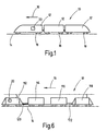
- FIG. 1 schematically shows a track-bound, driven system 10 (hereafter also called train 10), which comprises a total of three vehicles 12.
- train 10 which comprises a total of three vehicles 12.
- at least one of the vehicles 12 is a traction vehicle, that is, via this is a drive energy for moving the system 10 along a route 14 in the direction of travel 16 can be applied.
- the necessary, not shown drive system comprises at least one drive, if necessary also several drives that act on one or more of the wheelsets 18. hereby takes place in a known manner, a transmission of the drive energy of the Wheelsets 18 on the route 14.
- distributed drives are available, that is, the drive power is via wheelsets 18 of several vehicles 12 of a system 10 applied simultaneously.
- the route 14 is known from a arranged on a corresponding substructure track with two rails.
- the route 14 is according to topographic conditions laid, that is, the route 14 may inclines and slopes and arches show different radii.
- the system 10 is a track bound system, independent What kind of drive energy is applied.
- These can be for example rail-bound Systems (high-speed trains, freight trains, trains or the like) or Magnetschwebenmer, where no direct physical contact between the system 10 and the route 14 consists.
- the system 10 includes a device, generally designated 20, for determining a momentary tensile force of the system 10. Under current tensile force, the tensile force understood at any time t, in which the system 10 with any Speed v moves in the direction of travel 16 along the route 14, is required.
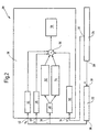
- FIG. 2 shows a block diagram of the device 20.
- the device 20 comprises an inertial Measuring system 22, a speed measuring device 24 and a detection and Evaluation unit 26.
- a first signal output 28 of the speed measuring device 24 is connected to an input 30 of the inertial measuring system 22.
- One second signal output 32 of the speed measuring device 24 is connected to a first Input 34 of the detection and evaluation unit 26 connected.
- a signal output 36 of the inertial measuring system 22 is connected to inputs 38, 40 and 42 of the detection and Evaluation unit 26 connected.
- the detection and evaluation unit 26 comprises circuit components 44, 46, 48, 50, 52, 54, 56 and 58, whose importance and function are discussed in more detail below becomes.
- the device 20 in connection with the system 10 has the following function:
- the instantaneous tensile force of the system 10 is to be determined. This is based on the initial consideration that in order to move the system 10 in the direction of travel 16, this requires a traction that overcomes all of the system 10 acting driving resistances.
- the tractive force is transmitted via the driven wheel sets 18, optionally a plurality of wheel sets 18, which may be distributed over the individual vehicles 12, to the travel path 14 (rails) in the direction of travel 16.
- the number of driven wheelsets 18 act Generalzug devis, the sum of the total tensile force of the system 10.
- the running resistance F wl and the arc resistance F wb are always positive, while the inclination resistance F wn (at Gradient) and the acceleration resistance F wa (during deceleration) can assume positive as well as negative values.
- These individual driving resistances of the system 10 can be determined either for the entire system 10 by means of a device 20. According to a further embodiment, it can be provided that the individual driving resistances for each vehicle 12 of the system 10 are determined separately. For this purpose, a corresponding number of detection and evaluation units 26, each associated with a vehicle 12, would then be required. When determining the individual driving resistances, only one inertial measuring system 22 and one speed measuring device 24 at a certain point of the system 10 are required. At this point, the inputs of the circuit components 44, 46, 48, 52, 54 and 50 are measured and latched. To determine the individual driving resistances, the knowledge of the distances s i of the individual vehicles 12 (or their bogies) is necessary.
- the output variables of the inertial measuring system 22 are then assigned to the circuit components of the individual vehicles, and thus the individual driving resistances are determined.
- the Einzeifahrwiderand for driven and non-powered vehicles can be determined separately.
- the tensile force of a system 10 is determined by when the tensile force for at least one driven vehicle via the determination of the total driving resistance and the required traction for non-powered vehicles by a direct Switzerlandstation, for example, after the known tow hook -Meßhabilit, is determined. Can be detected on the tensile force F to - as already explained - by summation of the so ascertainable individual driving resistance, the total road load of the system 10 over the results then.
- the individual driving resistances are dependent on a number of boundary conditions, which are known in a particular system 10, however.
- the running resistance F wl the arc resistance F wb and the inclination resistance F wn is approximately proportional to the weight G, while the acceleration resistance F wa is linearly connected to the mass m of the system 10.
- the running resistance F wl depends on the aerodynamic shape of the system 10, which can be expressed by the product of air resistance C w and cross-sectional area A in the direction of travel 16.
- the acceleration resistance is determined.
- F wa m ⁇ a x ( ⁇ + 1), where a x is the heading of the system 10 in the direction of travel 16, m is the mass of the system 10 and ⁇ is a weighting factor for a rotational mass fraction of the system 10.
- the mass m and the weighting factor p are known as the constant of the system 10.
- the acceleration a x is provided at the input 42 from the inertial measuring system 22, as will be explained in more detail later.
- the acceleration resistance F wa is proportional to the force that must be applied for a change in speed. In steady state of the system 10, the acceleration resistance F wa is not present. During acceleration of the system 10, an inertial force must be overcome, which can be considered as a damping resistance F wa . In this case, in addition to the translation acceleration of the total mass m, an angular acceleration of the rotating masses of the system 10 must also be taken into account. The rotational energy of the rotating masses can each be replaced by the translational energy of an additional mass.
- the acceleration resistance F wa of the system 10 can thus be determined with knowledge of the mass m of the weighting factor p and the acceleration a x in the direction of travel 16.
- the factor p is, for example, 0.02 to 0.12 for passenger coaches and freight cars, 0.08 to 0.18 for electric railcars, 0.15 to 0.30 for electric locomotives and 0.06 to 0.30 for the average of a locomotive train 0.10.
- the size of the weighting factor p for the rotary mass fraction is weighted according to a total mass m of the system. For empty or loaded (passengers, goods to be transported) systems 10 results in a different weighting factor p of the rotational mass fraction, since the total mass m changes with the load of the system 10.
- the inclination resistance F wn of the system 10 is determined.
- the angle of inclination ⁇ is provided by the inertial measuring system 22 at the input 40 of the detection and evaluation unit 26, as will be explained below.
- the mass m and the gravitational acceleration g are known as constants.
- the sheet resistance F wb of the system 10 is determined.
- the sheet resistance F wb is formed in addition to the running resistance Fwl by the running of the system 10 in track curves.
- the centrifugal forces increase quadratically at increasing speed v and are compensated, for example, in part by civil engineering measures, for example an elevation of the curve-outside rail of the travel path 14.
- the bow resistance F wb is an additional frictional resistance that arises when driving on track curves.
- the cause lies in the unequal way the rigidly connected wheels (inner wheel and outer wheel at Bogenfahrt) of the wheelsets 18.
- the given by the rigid connection of the wheels tracking the wheelsets leads to an inclination of the wheelsets at bow travel, which lead to an increase in the frictional resistance.
- the flange of the outer wheel is pressed at arc travel by the centrifugal force against the rail, so that a further frictional resistance is given.
- the arc resistance F wb is thus dependent on the geometric conditions of the route 14, in particular the radius of curvature r, the gauge of the route 14, the elevation of the outer rail and a track extension in the bow. Further, the arc resistance F wb of the vehicles 12 of the system 10, such as a wheelbase, a Radialein suitkeit the wheelsets 18 dependent. Further, the arc resistance F wb is dependent on a condition of the wheel-rail contact, for example due to wheel flange and / or rail wear, the effect of wheel flange lubrication, wet or dry rails.
- the circuit component becomes 52 and at arc radii r ⁇ 300 m is the circuit component 54 ( Figure 2) of the detection and evaluation 26 activated.
- a signal corresponding to the radius of curvature r lies at the entrance 38 which, as will be explained later, is available from the inertial measuring system 22 is provided.
- the circuit component 50 (FIG. 2) of the detection and evaluation unit 26 is used to determine 45 the running resistance F wl .
- the running resistance F wl is composed of the rolling resistance of the wheels on the guideway 14, the frictional resistance of the bearings and rotating drive components and the air resistance of the system 10.
- the running resistance F wl is always positive.
- the coefficient c 0 indicates the velocity-independent component. This primarily takes into account the rolling friction between the wheel and the rail, the bearing and the spring friction, the friction of the rotating drive parts and the influence of rail joints or the like.
- the coefficient C 1 of the linear member (C 1 ⁇ v) takes into account the movement-inhibiting influence of air currents.
- the coefficient C2 takes into account the air resistance (arerodynamic resistance) of the system 10, which is proportional to the square of the velocity v.
- the numerical values of the coefficients C 0 , C 1 and C 2 are known for known systems 10 and are obtained, for example, during test runs. These coefficients C 0 , C 1 and C 2 can be stored in a table and retrieved depending on the type of vehicles 12 used in the system 10 in consideration of the driving resistance F v .
- an average may be used for simplicity are formed from the coefficients of the individual vehicles 12.
- the running resistance F wl of individual vehicles 12 or of a system 10 can be determined, for example, by a so-called run-out test, in which the system 10 or a vehicle 12 is driven without drive over a defined driving route. In accordance with the effects of friction, the air currents and the aerodynamic resistance, this results in a deceleration of the rolling system 10 or of the vehicles 12, ie a negative acceleration, via which the running resistance F wl can be determined.
- the speed v needed to determine the running resistance F wl is present as a signal at the input 34 and is provided by the speed measuring device 24 , as will be explained below.
- the individual driving resistances F wa , F wn , F wb and F wl are determined and supplied to the formed as a summing circuit component 56. This forms the sum and thus the total driving resistance F w of the system 10.
- tensile force F to equal to the negative driving resistance F w can now be determined via the circuit component 58, the instantaneous tensile force F to the system 10.
- the instantaneous tensile force F can be, for example, in their time characteristic store and / or display, for example on a display screen.
- the acceleration a x in the direction of travel 16 the inclination angle ⁇ , the radius of curvature r and the instantaneous speed v are required. These measured quantities must be provided in real time - to determine the instantaneous total driving resistance F w and thus the instantaneous tractive force F zu .
- the inertial measuring system 22 and the speed measuring device 24 is provided.
- the running resistance F wl is speed-dependent, so that at the input 34, the instantaneous speed signal v must be provided. This is determined by the speed measuring device 24, for example, by detecting the ground speed.
- the driving speed v can be detected, for example, with an incremental encoder on a passive wheel set 18, that is, on a non-drivable and non-brakable wheelset 18. In this case, 18 pulses are generated with each revolution of the wheelset, so that it is possible to determine the speed v in a simple manner with a known extent and measured frequency of the pulses of the incremental encoder.
- the actual speed can also be determined by means of other known methods, for example satellite-based methods (GPS) or radar measuring methods.
- GPS satellite-based methods
- the acceleration a x of the system 10 in the direction of travel 16 can be determined from the speed signal v by differentiation.
- the detection of the distance traveled over the speed v is possible, which is necessary for the separate detection of the driving resistance of the individual vehicles.
- the inertial measuring system 22 has a known per se Gyro arrangement with which the accelerations in all three spatial directions, as well the rotation rates around all spatial axes can be measured.
- the radius of curvature r can look like this the velocity v and the yaw rate about the system vertical axis are determined.
- a determination of the slope and cant of arcs is from the rates of rotation possible around the system longitudinal axis and the system transverse axis.
- centrifugal-based inertial measuring systems 22 Function and construction of such centrifugal-based inertial measuring systems 22 are known, so that in the context of the present description thereto should not be discussed in detail. It is crucial that with such inertial Measuring Systems 22 Accelerations, rotation rates and the positional angles of a moving Body, here the moving system 10, can be determined.
- the inertial measuring system 22 is arranged at a defined location of the system 10. This ensures that this system is fixed, so that the inertial Measuring system 22 is subjected to the same dynamic influences as the System 10.
- FIG. 6 schematically shows a train 10 which can be moved along the route 14 by a traction vehicle 112 designed as an electric locomotive.
- the tensile force F is to be detected to the traction unit 112, which exerts this on the train 10.
- the train 10 comprises in addition to the traction vehicle 112 a measuring carriage 114, a support vehicle 116 and a brake drive vehicle 118.
- the traction unit 112 is coupled to the measuring carriage 114 via a known Buchkraftmeßkupplung 120. This Buchkraftmeßkupplung 120 serves only to verify the instantaneous values supplied by the device 20 to the tension F. During an actual test drive can be dispensed with the arrangement of Switzerlandkraftmeßkupplung 120.
- the brake truck 118 is connected to the backing carriage 116 via a brake power hook 122.
- the brake truck 118 is for simulating the load of a train of a plurality of vehicles 12 (FIG. 1). If the brake drive vehicle 118 is pulled along by the traction vehicle 112, a braking torque acts. The resulting additional braking force is detected by the Bremszugkrafthaken 122 and taken into account in the determination of the acceleration resistance F wa by addition.
- the acceleration resistance F wa the inclination resistance F wn , the arc resistance F wb and the running resistance F wl . determined.
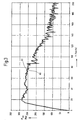
- FIG 3 two traction characteristics are shown, wherein the tensile force F is registered to over the speed v.
- a first tensile force characteristic curve 60 shows the course of the traction force F determined by means of the device 20th
- a second curve 62 shows the course of the tensile force F which has been determined only for verification purposes using the Glaskraftmeßkupplung 120th
- the substantially congruent course of the characteristic curves 60 and 62 it is clear that can be provided by the device 20 and performed by the apparatus 20 method for determining the tensile force F to be very exact values. These are provided without, as in the Switzerlandkraftmeßkupplung 120, a direct tensile force measurement.
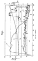
- FIG. 4 shows the course of the individual driving resistances over the speed v for clarification.
- the braking force F br and the damping resistance F wa and on the right the inclination resistance F wn the arc resistance F wb and the running resistance F wl are scaled.
- a characteristic curve 64 illustrates the course of the braking force F br , which takes into account the load simulated via the brake drive vehicle 118.
- a characteristic curve 66 shows the course of the acceleration resistance F wa , which takes into account the force component required for mass acceleration of the train 10.
- a curve 68 represents the course of the inclination resistance F wn taking into account gradients and slopes of the route 14.
- a characteristic curve 70 represents the course of the sheet resistance F wb . The test travel documented here is a route 14 without arcs, so that the characteristic curve 70 essentially runs on the zero line.
- characteristic 72 is entered, which identifies the course of the running resistance F wl . It is clear that with increasing speed v, the running resistance F wl increases exponentially.
- FIG. 5 shows the inclination resistance F wn over the distance s of the travel path 14.
- a first characteristic curve 74 represents the course of the inclination resistances F wn measured by the device 20, while a second characteristic curve 76 represents for comparison the inclination of the travel path 14 taken from a known route file .
- the measured inclination resistance F wn substantially coincides with the actual slope course of the route 14. This results in a further advantage that a route file of routes 14, which are only very expensive to build, for the determination of the inclination resistance F wn per se is not needed.
- a more accurate measurement is possible by means of the instantaneous measurement of the inclination resistance F wn , since here the actual momentary track conditions are taken into account, which may deviate from calculated expected track ratios stored in a track file .
Abstract
Description
Die Erfindung betrifft ein Verfahren zur Ermittlung einer Zugkraft eines spurgebundenen, angetriebenen Systems, das wenigstens ein Fahrzeug umfaßt sowie eine Vorrichtung zur Durchführung des Verfahrens, mit den im Oberbegriff des Anspruchs 8 genannten Merkmalen.The invention relates to a method for determining a tensile force of a track-bound, driven system comprising at least one vehicle and a device to carry out the method, with the in the preamble of claim 8 mentioned features.
Verfahren und Vorrichtungen zur Ermittlung einer Zugkraft eines spurgebundenen, angetriebenen Systems sind bekannt. Unter spurgebundene, angetriebene Systeme werden beispielsweise schienengebundene Züge, die wenigstens ein Triebfahrzeug umfassen, Schnellbahnen, Magnetschwebebahnen oder dergleichen verstanden. Diese Systeme werden durch wenigstens ein Triebfahrzeug entlang einer vorgegebenen Fahrstrecke bewegt. Üblicherweise verkehren derartige spurgebundene, angetriebene Systeme in einem Taktfahrplan, das heißt, zu festgelegten Zeitpunkten müssen diese Systeme eine bestimmte Position auf der bekannten Fahrstrecke aufweisen. Hierzu bewegen sich diese Systeme mit einer Geschwindigkeit entlang der Fahrstrecke. Um diese notwendige Geschwindigkeit zu erreichen, ist das Aufbringen einer Antriebskraft notwendig, mittels der das System in Bewegung gesetzt wird. Die benötigte Antriebsenergie ist zum einen abhängig von einer Topographie der Fahrstrecke, wie beispielsweise Steigungen, Gefälle, Bogenfahrten oder dergleichen und andererseits von Parametern des Systems selber, wie beispielsweise Masse oder dergleichen.Method and devices for determining a tensile force of a track-bound, driven Systems are known. Under track-bound, powered systems will be for example, rail-bound trains comprising at least one traction unit, Railways, magnetic levitation trains or the like understood. These Systems are driven by at least one traction vehicle along a predetermined Driving distance moved. Usually run such track-bound, driven Systems in a timetable, that is, at fixed times must this Systems have a certain position on the known route. For this These systems move at a speed along the route. Around To achieve this necessary speed is the application of a driving force necessary, by means of which the system is set in motion. The required drive energy is on the one hand dependent on a topography of the route, such as Gradients, gradients, curves or the like and on the other hand of parameters the system itself, such as mass or the like.
Beim bestimmungsgemäßen Einsatz der gattungsgemäßen spurgebundenen, angetriebenen Systeme besitzen diese eine bestimmte, bekannte Antriebsleistung. Für die Einbindung der Systeme in einen Taktfahrplan ist nunmehr erforderlich zu überprüfen, ob diese Antriebsleistung ausreichend ist, entsprechend der gegebenen Systemparameter und Streckentopographie eine ausreichende Antriebskraft (nachfolgend Zugkraft) aufzubringen. Eingesetzte Triebfahrzeuge besitzen eine Zugkraftkennlinie, die die Zugkraft über der Geschwindigkeit beinhaltet. Zum Ermitteln dieser Zugkraftkennlinie beziehungsweise zum Überprüfen einer vorgegebenen Zugkraftkennlinie ist bekannt, eine momentane Zugkraft während einer Fahrt des angetriebenen Systems zu ermitteln. Zum Ermitteln der Zugkraft ist ein sogenanntes Meßradsatz-Verfahren, ein Hohlwellen-Verfahren und ein Zughaken-Meßverfahren bekannt. Bei dem Meßradsatz-Verfahren lassen sich Längs-, Quer- und Aufstandskräfte zwischen Rad und Schiene der an der Zugkraftübertragung beteiligten Radsätze erfassen. Die hierbei gemessenen Zugkräfte resultieren aus elastischen Verformungen von Radsatzwellen und -rädern, die mittels Dehnungsmeßstreifen erfaßt und mit Hilfe eines Rechners in die am Rad wirkenden Längs- und Querkräfte umgerechnet werden. Beim Hohlwellen-Verfahren werden bei Triebfahrzeugen mit einseitigen Kardanhohlwellenantrieben die Zugkräfte in beiden Radaufstandspunkten eines Radsatzes über Messungen eines Hohlwellendrehmomentes und dem bekannten Laufkreisradius der Räder ermittelt. Hierzu ist die Anordnung von Dehnungsmeßstreifen an der Hohlwelle erforderlich. Bei dem bekannten Zughaken-Meßverfahren wird das Triebfahrzeug mit einer Anhängelast (weitere Fahrzeuge, Wagen eines Zuges) über eine Zugkraftmeßkupplung verbunden. Diese Zugkraftmeßkupplung umfaßt biege- und temperaturkompensierte Dehnungsmeßstreifen, mittels denen auf die Kupplung wirkende Zugkräfte erfaßbar sind.When used according to the purpose of the generic track-bound, driven Systems have these a certain, known drive power. For the integration The systems in a timetable is now required to check whether this drive power is sufficient, according to the given system parameters and track topography sufficient driving force (hereinafter tensile force) apply. Used traction vehicles have a tensile force characteristic that the traction above the speed. For determining this tensile force characteristic or for checking a predetermined tensile force characteristic is known, a to determine instantaneous tractive force during a drive of the driven system. To determine the tensile force is a so-called Meßradsatz method, a hollow shaft method and a towing hook measuring method. In the Meßradsatz method can be longitudinal, lateral and contact forces between the wheel and rail at the Traction transmission involved wheel sets capture. The measured tensile forces result from elastic deformations of wheelsets and wheels, by means of Detected strain gauges and acting with the help of a computer in the wheel Longitudinal and shear forces are converted. In the hollow shaft method are at Traction vehicles with unilateral cardan hollow shaft drives the tensile forces in both Radaufstandspunkte a wheelset on measurements of a hollow shaft torque and the known radius of the wheels. This is the arrangement required by strain gauges on the hollow shaft. In the known Towing hook measuring method is the traction vehicle with a trailer load (other vehicles, Carriage of a train) connected via a Zugkraftmeßkupplung. These Zugkraftmeßkupplung includes bending and temperature compensated strain gauges, by means of which acting on the coupling tensile forces can be detected.
Bei den bekannten Zugkraft-Meßverfahren ist nachteilig, daß diese eine sehr aufwendige meßtechnische Anordnung zur direkten Zugkraftmessung erfordern. Ferner ist nachteilig, daß zur Ermittlung einer resultierenden Zugkraft aller Räder eine entsprechende Anzahl von Zugmeßeinrichtungen vorzusehen ist, deren einzelne Meßergebnisse addiert werden müssen. Bei dem Meßradsatz-Verfahren müssen hierzu insgesamt acht Radumfangskräfte und beim Hohlwellen-Verfahren vier Radumfangskräfte berücksichtigt werden. Neben hiermit gegebenen zusätzlichen Fehlerquellen ist nachteilig, daß nicht nur die statischen Anteile der auftretenden Drehmomente, sondern auch dynamische Anteile der Drehmomente erfaßt werden, die als Eigenschwingungsformen des Antriebsstranges auftreten. Hierdurch sind diese Verfahren mit einem Fehler behaftet.In the known tensile force measuring method is disadvantageous that this is a very expensive require metrological arrangement for direct Zugkraftmessung. Further is disadvantageous in that for determining a resulting tensile force of all wheels a corresponding Number of Zugmeßeinrichtungen is to provide their individual measurement results must be added. In the Meßradsatz method must do this in total eight Radumfangskräfte and the hollow shaft method four Radumfangskräfte be taken into account. Besides hereby given additional sources of error disadvantageous that not only the static components of the torques occurring, but Also dynamic portions of the torques are detected, which are natural vibration modes of the drive train occur. As a result, these methods are with an error afflicted.
Beim Einsatz einer Zugkraftmeßkupplung ist nachteilig, daß diese ausschließlich bei angetriebenen Systemen mit einem Triebfahrzeug und an das Triebfahrzeug angehängten Fahrzeugen als Last möglich ist.When using a Zugkraftmeßkupplung is disadvantageous that this exclusively at powered systems with a traction unit and attached to the traction unit Vehicles as a load is possible.
Bei den bekannten Verfahren ist ferner nachteilig, daß diese in spurgebundenen, angetriebenen Systemen mit verteiltem Antrieb und spurgebundenen, angetriebenen Systemen ohne unmittelbaren Berührungskontakt zwischen System und Fahrweg, wie beispielsweise bei Magnetschwebebahnen, nicht einsetzbar sind.In the known methods is also disadvantageous that these in track-bound, driven Distributed drive systems and track-bound, powered systems without direct physical contact between system and infrastructure, such as in magnetic levitation railways, are not used.
Aus IMAR, Gesellschaft inertiale Meß-, Automatisierungs- und Regelsysteme, Meßsystem zur inertialen kinematischen Vermessung, Version 1.5, 1997 sind inertiale Meßsysteme bekannt, mittels denen Beschleunigungen, Drehraten und Lagewinkel eines bewegten Körpers bestimmbar sind. From IMAR, society inertial measuring, automation and control systems, measuring system for inertial kinematic measurement, Version 1.5, 1997 are inertial measuring systems Known by means of which accelerations, rotation rate and angle of a Movable body can be determined.
Nach DE-OS 42 28 413 ist ein Verfahren zur Bestimmung der Masse eines durch Vertriebskräfte in seine Längsrichtung bewegten Kraftfahrzeuges bekannt, wobei
- wenigstens zwei Längsbeschleunigungen zu wenigstens zwei unterschiedlichen Zeitpunkten erfaßt werden, und
- die zu diesen Zeitpunkten vorliegenden Vortriebskräfte erfaßt werden, und
- aus der Differenz der Vertriebskräfte und der Differenz der Längsbeschleunigungen die Fahrzeugmasse bestimmt wird.
- at least two longitudinal accelerations are detected at at least two different times, and
- the propulsive forces present at those times are recorded, and
- from the difference of the sales forces and the difference of the longitudinal accelerations the vehicle mass is determined.
Dieses Verfahren ist ausschließlich auf Straßen-Kraftfahrzeuge bezogen, wobei die Masse dieses Kfz. bestimmt wird. Die Masse ist nur für die Ermittlung der Beschleunigungskraft von Bedeutung. Für alle anderen Kriterien, so auch für den Fahrwiderstand, ist die Masse eines Fahrzeuges nicht relevant.This method is exclusively related to road vehicles, with the Mass of this car. is determined. The mass is only for the determination of the acceleration force significant. For all other criteria, including the driving resistance, the mass of a vehicle is not relevant.
Der Erfindung liegt die Aufgabe zugrunde, ein Verfahren und eine Vorrichtung zur Ermittlung einer Zugkraft eines spurgebundenen, angetriebenen Systems anzugeben, mittels denen ein meßtechnischer Aufwand unter Beibehaltung einer hohen Genauigkeit reduziert ist und der Einsatz bei allen spurgebundenen, angetriebenen Systemen möglich ist.The invention is based on the object, a method and a device for determining indicate a traction of a track-bound, powered system, by means of which a metrological effort while maintaining a high accuracy is reduced and the use of all track-bound, driven systems is possible.
Erfindungsgemäß wird diese Aufgabe durch ein Verfahren mit den im Anspruch 1 genannten Merkmalen gelöst. Dadurch, daß der momentane Gesamtfahrwiderstand des spurgebundenen, angetriebenen Systems erfaßt wird und hieraus die Zugkraft ermittelt wird, ist vorteilhaft möglich, die Zugkraft indirekt über den Gesamtfahrwiderstand zu ermitteln, so daß auf aufwendige direkt kraftmessende Anordnungen verzichtet werden kann. Da die aufzubringende Zugkraft bei Fahrt des angetriebenen Systems mit bestimmter Geschwindigkeit exakt dem zu überwindenden Gesamtfahrwiderstand entspricht, läßt sich so in einfacher Weise durch Ermittlung des Gesamtfahrwiderstandes auf die tatsächliche momentane Zugkraft schließen. Insgesamt wird somit ein Meßverfahren bereitgestellt, das mit einem reduzierten Meßaufwand eine Zugkraft mit hoher Genauigkeit in Echtzeit ermitteln kann.According to the invention this object is achieved by a method with the mentioned in claim 1 Characteristics solved. Due to the fact that the instantaneous overall travel resistance of the track-bound, driven system is detected and determines the tensile force is, is advantageously possible, the traction indirectly over the total driving resistance too determine, so that to dispense with complex direct force measuring arrangements can. Since the applied tensile force when driving the driven system with certain Speed exactly corresponds to the total travel resistance to be overcome, can be so easily by determining the total driving resistance close to the actual momentary pull. Overall, therefore, a measuring method provided that with a reduced Meßaufwand a tensile force with high Determine accuracy in real time.
In bevorzugter Ausgestaltung der Erfindung ist vorgesehen, daß der momentane Gesamtfahrwiderstand aus einer Summe von momentanen Einzelfahrwiderständen ermittelt wird, wobei insbesondere als Einzelfahrwiderstände ein Laufwiderstand, ein Bogenwiderstand, ein Neigungswiderstand und ein Beschleunigungswiderstand ermittelt werden. Durch eine derartige Ermittlung des Gesamtfahrwiderstandes lassen sich in einfacher Weise die Fahrwiderstände des gesamten spurgebundenen, angetriebenen Systems ermitteln, das heißt, aller einzelner Fahrzeuge des Systems. Hierdurch läßt sich mit hoher Genauigkeit der Gesamtfahrwiderstand ermitteln, da sämtliche diesen Fahrwiderstand beeinflussenden Komponenten des gesamten Systems, also alle einzelne Fahrzeuge des Systems, bei der Ermittlung Berücksichtigung finden.In a preferred embodiment of the invention, it is provided that the instantaneous Gesamtfahrwiderstand determined from a sum of instantaneous individual driving resistances is, in particular as a single running resistances a running resistance, an arc resistance, a pitch resistance and an acceleration resistance determined become. By such a determination of the total driving resistance can be in easy way the driving resistance of the entire track-bound, driven Detecting systems, that is, all the individual vehicles of the system. This leaves determine with high accuracy of the total driving resistance, since all this Driving resistance influencing components of the entire system, so all individual Vehicles of the system, are taken into account in the investigation.
Durch das erfindungsgemäße Verfahren wird insgesamt möglich, in Kenntnis einer momentanen Geschwindigkeit, die durch an sich bekannte Meßverfahren ermittelbar ist, jederzeit die momentane Zugkraft zu ermitteln. Durch Ableitung der momentanen Zugkraft aus dem momentanen Gesamtfahrwiderstand ist eine direkte Kraftmessung nicht erforderlich. Hierdurch ist eine wesentliche Vereinfachung des gesamten Meßverfahrens möglich. Insbesondere auch bei verteilten Antrieben kann so die momentane Zugkraft des gesamten angetriebenen Systems ermittelt werden.The inventive method is possible in total, in knowledge of one instantaneous speed, which can be determined by measuring methods known per se is to determine the instantaneous traction at any time. By derivation of the current Traction from the current total driving resistance is a direct force measurement not mandatory. This is a significant simplification of the entire measurement process possible. Especially with distributed drives so can the current Traction of the entire driven system can be determined.
Erfindungsgemäß wird die Aufgabe ferner durch eine Vorrichtung mit den im Anspruch 8 genannten Merkmalen gelöst. Dadurch, daß wenigstens ein systemfest angeordnetes inertiales Meßsystem zur Ermittlung der momentanen Beschleunigung des Systems in den drei Raumrichtungen und der momentanen Drehraten um die drei Raumachsen und eine Meßeinrichtung zur Ermittlung der momentanen Geschwindigkeit des Systems und eine Erfassungs- und Auswerteeinheit zur Ermittlung eines momentanen Gesamtfahrwiderstandes vorgesehen sind, lassen sich in einfacher Weise die für die Ermittlung des momentanen Gesamtfahrwiderstandes benötigten Meßgrößen abgreifen, so daß über die Erfassungs- und Auswerteeinheit ohne direkte Kraftmessung die momentane Zugkraft des Systems enmittelbar ist.According to the invention the object is further by a device with the in the claim 8 mentioned features solved. Characterized in that at least one system fixedly arranged inertial measuring system for determining the instantaneous acceleration of the system in the three spatial directions and the instantaneous rotation rates around the three spatial axes and a measuring device for determining the instantaneous speed of the system and a detection and evaluation unit for determining a current total driving resistance are provided, can be easily for the determination tapping the measured variables required by the instantaneous total travel resistance so that via the detection and evaluation unit without direct force measurement the instantaneous Traction of the system is mediate.
Weitere bevorzugte Ausgestaltungen der Erfindung ergeben sich aus den übrigen, in den abhängigen Ansprüchen genannten Merkmalen.Further preferred embodiments of the invention will become apparent from the others, in The features mentioned in the dependent claims.
Die Erfindung wird nachfolgend in einem Ausführungsbeispiel anhand der zugehörigen Zeichnungen näher erläutert. Es zeigen:
- Figur 1
- schematisch ein spurgebundenes, angetriebenes System;
- Figur 2
- ein Blockschaltbild einer Vorrichtung zur Ermittlung einer Zugkraft des Systems;
- Figur 3
- eine mit dem erfindungsgemäßen Verfahren ermittelte Zugkraftkennlinie;
- Figur 4
- Kennlinien von Einzelfahrwiderständen des Systems;
- Figur 5
- ein mit dem erfindungsgemäßen Verfahren ermittelter Verlauf eines Neigungswiderstandes;
- Figur 6
- schematisch ein konkretes Ausführungsbeispiel eines Systems und
- Figur 7
- schematisch ein System nach einem weiteren Ausführungsbeispiel.
- FIG. 1
- schematically a track bound, powered system;
- FIG. 2
- a block diagram of a device for determining a tensile force of the system;
- FIG. 3
- a determined by the method according to the invention tensile force characteristic;
- FIG. 4
- Characteristic curves of individual driving resistances of the system;
- FIG. 5
- a determined by the method according to the invention gradient of a pitch resistance;
- FIG. 6
- schematically a concrete embodiment of a system and
- FIG. 7
- schematically a system according to another embodiment.
Figur 1 zeigt schematisch ein spurgebundenes, angetriebenes System 10 (nachfolgend auch Zug 10 genannt), das insgesamt drei Fahrzeuge 12 umfaßt. Selbstverständlich sind weitere Ausführungsbeispiele mit weniger oder mehr als drei Fahrzeugen 12 möglich. Innerhalb des Systems 10 ist wenigstens eines der Fahrzeuge 12 ein Triebfahrzeug, das heißt, über dieses ist eine Antriebsenergie zur Bewegung des Systems 10 entlang einer Fahrstrecke 14 in Fahrtrichtung 16 aufbringbar. Das hierzu notwendige, nicht näherdargestellte Antriebssystem umfaßt wenigstens einen Antrieb, gegebenenfalls auch mehrere Antriebe, die auf ein oder mehrere der Radsätze 18 wirken. Hierdurch erfolgt in bekannter Weise eine Übertragung der Antriebsenergie von den Radsätzen 18 auf die Fahrstrecke 14. Gegebenenfalls sind auch verteilte Antriebe vorhanden, das heißt, die Antriebsenergie wird über Radsätze 18 von mehreren Fahrzeugen 12 eines Systems 10 gleichzeitig aufgebracht. Die Fahrstrecke 14 besteht bekannterweise aus einem auf einem entsprechenden Unterbau angeordneten Gleis mit zwei Schienen. Die Fahrstrecke 14 ist entsprechend topographischer Gegebenheiten verlegt, das heißt, die Fahrstrecke 14 kann Steigungen und Gefälle sowie Bögen mit unterschiedlichen Radien aufweise.FIG. 1 schematically shows a track-bound, driven system 10 (hereafter also called train 10), which comprises a total of three vehicles 12. Of course Further embodiments with fewer or more than three vehicles 12 are possible. Within the system 10, at least one of the vehicles 12 is a traction vehicle, that is, via this is a drive energy for moving the system 10 along a route 14 in the direction of travel 16 can be applied. The necessary, not shown drive system comprises at least one drive, if necessary also several drives that act on one or more of the wheelsets 18. hereby takes place in a known manner, a transmission of the drive energy of the Wheelsets 18 on the route 14. Optionally, distributed drives are available, that is, the drive power is via wheelsets 18 of several vehicles 12 of a system 10 applied simultaneously. The route 14 is known from a arranged on a corresponding substructure track with two rails. The route 14 is according to topographic conditions laid, that is, the route 14 may inclines and slopes and arches show different radii.
Bei dem System 10 handelt es sich um ein spurgebundenes System, unabhängig auf welche Art die Antriebsenergie aufgebracht wird. Dies können beispielsweise schienengebundene Systeme (Hochgeschwindigkeitszüge, Güterzüge, Schnellbahnen oder dergleichen) sein oder Magnetschwebezüge, bei denen kein unmittelbarer Berührungskontakt zwischen dem System 10 und der Fahrstrecke 14 besteht.The system 10 is a track bound system, independent What kind of drive energy is applied. These can be for example rail-bound Systems (high-speed trains, freight trains, trains or the like) or Magnetschwebenzüge, where no direct physical contact between the system 10 and the route 14 consists.
Das System 10 umfaßt eine insgesamt mit 20 bezeichnete Vorrichtung zum Ermitteln einer momentanen Zugkraft des Systems 10. Unter momentaner Zugkraft wird die Zugkraft verstanden, die zu einem beliebigen Zeitpunkt t, bei dem das System 10 mit beliebiger Geschwindigkeit v sich in Fahrtrichtung 16 entlang der Fahrstrecke 14 bewegt, erforderlich ist.The system 10 includes a device, generally designated 20, for determining a momentary tensile force of the system 10. Under current tensile force, the tensile force understood at any time t, in which the system 10 with any Speed v moves in the direction of travel 16 along the route 14, is required.
Figur 2 zeigt ein Blockschaltbild der Vorrichtung 20. Die Vorrichtung 20 umfaßt ein inertiales Meßsystem 22, eine Geschwindigkeitsmeßeinrichtung 24 sowie eine Erfassungsund Auswerteeinheit 26. Ein erster Signalausgang 28 der Geschwindigkeitsmeßeinrichtung 24 ist mit einem Eingang 30 des inertialen Meßsystems 22 verbunden. Ein zweiter Signalausgang 32 der Geschwindigkeitsmeßeinrichtung 24 ist mit einem ersten Eingang 34 der Erfassungs- und Auswerteeinheit 26 verbunden. Ein Signalausgang 36 des inertialen Meßsystems 22 ist mit Eingängen 38, 40 und 42 der Erfassungs- und Auswerteeinheit 26 verbunden.Figure 2 shows a block diagram of the device 20. The device 20 comprises an inertial Measuring system 22, a speed measuring device 24 and a detection and Evaluation unit 26. A first signal output 28 of the speed measuring device 24 is connected to an input 30 of the inertial measuring system 22. One second signal output 32 of the speed measuring device 24 is connected to a first Input 34 of the detection and evaluation unit 26 connected. A signal output 36 of the inertial measuring system 22 is connected to inputs 38, 40 and 42 of the detection and Evaluation unit 26 connected.
Die Erfassungs- und Auswerteeinheit 26 umfaßt Schaltungsbestandteile 44, 46, 48, 50, 52, 54, 56 und 58, auf deren Bedeutung und Funktion nachfolgend noch näher eingegangen wird.The detection and evaluation unit 26 comprises circuit components 44, 46, 48, 50, 52, 54, 56 and 58, whose importance and function are discussed in more detail below becomes.
Die Vorrichtung 20 in Verbindung mit dem System 10 zeigt folgende Funktion:The device 20 in connection with the system 10 has the following function:
Mittels der Vorrichtung 20 soll die momentane Zugkraft des Systems 10 ermittelt werden.
Hierbei liegt die Ausgangsüberlegung zugrunde, daß um das System 10 in Fahrtrichtung
16 bewegen zu können, dieses einer Zugkraft bedarf, die alle auf das System
10 wirkenden Fahrwiderstände überwindet. Die Zugkraft wird hierbei über die angetriebenen
Radsätze 18, gegebenenfalls mehrere Radsätze 18, die über die einzelnen
Fahrzeuge 12 verteilt sein können, auf die Fahrstrecke 14 (Schienen) in Fahrtrichtung
16 übertragen. Entsprechend der Anzahl der angetriebenen Radsätze 18 wirken Teilzugkräfte,
deren Summe die Gesamtzugkraft des Systems 10 ergeben. Bei Bewegung
des Systems 10 in Fahrtrichtung 16 ist die Zugkraft Fzu gleich dem Gesamtfahrwiderstand
Fw, so daß gilt:
Da der Gesamtfahrwiderstand Fw der Zugkraft entgegengerichtet ist, ist dieser in bezug auf die Fahrtrichtung 16 negativ.Since the total driving resistance F w is opposed to the tensile force, this is negative with respect to the direction of travel 16.
Anhand dieser Beziehung wird deutlich, daß die Zugkraft des Systems 10 ohne direkte Kraftmessung, wie dies bisher ausschließlich im Stand der Technik genutzt wird, durch Ermittlung des Gesamtfahrwiderstands Fw des Systems 10 möglich ist.From this relationship it is clear that the tensile force of the system 10 without direct force measurement, as previously used exclusively in the prior art, by determining the total driving resistance F w of the system 10 is possible.
Der Gesamtfahrwiderstand Fw des Systems 10 setzt sich aus einer Summe von Einzelfahrwiderständen
zusammen, wobei gilt:
Diese Einzelfahrwiderstände des Systems 10 können entweder für das gesamte System 10 mittels einer Vorrichtung 20 ermittelt werden. Nach einem weiteren Ausführungsbeispiel kann vorgesehen sein, daß die Einzelfahrwiderstände für jedes Fahrzeug 12 des Systems 10 getrennt ermittelt werden. Hierzu wären dann eine entsprechende Anzahl von Erfassungs- und Auswerteeinheiten 26, die jeweils einem Fahrzeug 12 zugeordnet sind, erforderlich. Bei der Ermittlung der einzelnen Fahrwiderstände ist nur ein inertiales Meßsystem 22 und eine Geschwindigkeitsmeßeinrichtung 24 an einer bestimmten Stelle des Systems 10 erforderlich. An dieser Stelle werden die Eingangsgrößen der Schaltungsbestandteile 44, 46, 48, 52, 54 und 50 gemessen und zwischengespeichert. Zur Bestimmung der Einzelfahrwiderstände ist die Kenntnis der Abstände si der einzelnen Fahrzeuge 12 (oder deren Drehgestelle) notwendig. Die Ausgangsgrößen des inertialen Meßsystems 22 werden dann unter Berücksichtigung des Abstandes si (Figur 7) den Schaltungsbestandteilen der einzelnen Fahrzeuge zugeordnet und damit die Einzelfahrwiderstände ermittelt. Mit derselben Anordnung können die Einzeifahrwiderstände für angetriebene und nicht angetriebene Fahrzeuge getrennt ermittelt werden.These individual driving resistances of the system 10 can be determined either for the entire system 10 by means of a device 20. According to a further embodiment, it can be provided that the individual driving resistances for each vehicle 12 of the system 10 are determined separately. For this purpose, a corresponding number of detection and evaluation units 26, each associated with a vehicle 12, would then be required. When determining the individual driving resistances, only one inertial measuring system 22 and one speed measuring device 24 at a certain point of the system 10 are required. At this point, the inputs of the circuit components 44, 46, 48, 52, 54 and 50 are measured and latched. To determine the individual driving resistances, the knowledge of the distances s i of the individual vehicles 12 (or their bogies) is necessary. Taking into account the distance s i (FIG. 7), the output variables of the inertial measuring system 22 are then assigned to the circuit components of the individual vehicles, and thus the individual driving resistances are determined. With the same arrangement, the Einzeifahrwiderstände for driven and non-powered vehicles can be determined separately.
Im Sinne der Erfindung ist auch, wenn die Zugkraft eines Systems 10 dadurch ermittelt wird, wenn die Zugkraft für wenigstens ein angetriebenes Fahrzeug über die Ermittlung von dessen Gesamtfahrwiderstand erfolgt und die erforderliche Zugkraft für nicht angetriebene Fahrzeuge durch eine direkte Zugkraftmessung, beispielsweise nach dem bekannten Zughaken-Meßverfahren, ermittelt wird. Durch Summation der so ermittelbaren Einzelfahrwiderstände ergibt sich dann der Gesamtfahrwiderstand des Systems 10, über den - wie bereits erläutert - auf die Zugkraft Fzu erkannt werden kann.In the context of the invention is also when the tensile force of a system 10 is determined by when the tensile force for at least one driven vehicle via the determination of the total driving resistance and the required traction for non-powered vehicles by a direct Zugkraftmessung, for example, after the known tow hook -Meßverfahren, is determined. Can be detected on the tensile force F to - as already explained - by summation of the so ascertainable individual driving resistance, the total road load of the system 10 over the results then.
Die einzelnen Fahrwiderstände sind von einer Reihe von Randbedingungen abhängig, die bei einem bestimmten System 10 jedoch bekannt sind. So ist der Laufwiderstand Fwl der Bogenwiderstand Fwb und der Neigungswiderstand Fwn näherungsweise proportional zur Gewichtskraft G, während der Beschleunigungswiderstand Fwa linear mit der Masse m des Systems 10 verknüpft ist. Ferner ist der Laufwiderstand Fwl von der aerodynamischen Form des Systems 10 abhängig, die sich durch das Produkt aus Luftwiderstand Cw und Querschnittsfläche A in Fahrtrichtung 16 ausdrücken lassen.The individual driving resistances are dependent on a number of boundary conditions, which are known in a particular system 10, however. Thus, the running resistance F wl the arc resistance F wb and the inclination resistance F wn is approximately proportional to the weight G, while the acceleration resistance F wa is linearly connected to the mass m of the system 10. Further, the running resistance F wl depends on the aerodynamic shape of the system 10, which can be expressed by the product of air resistance C w and cross-sectional area A in the direction of travel 16.
Hieraus ergibt sich als allgemeingültige Beziehung für den Gesamtfahrwiderstand:
Mittels des Schaltungsbestandteils 44 (Figur 2) der Erfassungs- und Auswerteeinheit 26
wird der Beschleunigungswiderstand ermittelt. Hierbei gilt die Beziehung.
Der Beschleunigungswiderstand Fwa ist proportional zu der Kraft, die für eine Veränderung
der Geschwindigkeit aufgebracht werden muß. Bei Beharrungsfahrt des Systems
10 ist der Beschleunigungswiderstand Fwa nicht vorhanden. Während einer Beschleunigung
des Systems 10 ist eine Trägheitskraft zu überwinden, die als Beschteunigungswiderstand
Fwa betrachtet werden kann. Hierbei muß neben der Translationsbeschleunigung
der Gesamtmasse m auch eine Winkelbeschleunigung der rotierenden
Massen des Systems 10 berücksichtigt werden. Die Rotationsenergie der rotierenden
Massen läßt sich jeweils durch die Translationsenergie einer Zusatzmasse ersetzen.
Hierbei gilt:
Mittels des Schaltungsbestandteils 46 (Figur 2) der Erfassungs- und Auswerteeinheit 26
wird der Neigungswiderstand Fwn des Systems 10 ermittelt. Der Neigungswiderstand
Fwn ist die entgegen der Bewegungsrichtung 16 positiv gezählte Komponente der Gewichtskraft
G des Zuges, die sogenannte Hangabtriebskraft. In der Ebene ist der Neigungswiderstand
Fwn = 0. Der Neigungswiderstand Fwn ergibt sich aus
Mittels der Schaltungsbestandteile 48, 52 und 54 (Figur 2) der Erfassungs- und Auswerteeinheit 26 wird der Bogenwiderstand Fwb des Systems 10 ermittelt. Der Bogenwiderstand Fwb entsteht zusätzlich zum Laufwiderstand Fwl durch den Lauf des Systems 10 in Gleisbögen. Bei der Bogenfahrt entstehen durch die Wirkung der Fliehkräfte Querkräfte zwischen Rad und Schiene. Die Fliehkräfte steigen bei größerwerdender Geschwindigkeit v quadratisch an und werden beispielsweise zum Teil durch bautechnische Maßnahmen, beispielsweise eine Überhöhung der kurvenäußeren Schiene des Fahrweges 14, kompensiert. By means of the circuit components 48, 52 and 54 (FIG. 2) of the detection and evaluation unit 26, the sheet resistance F wb of the system 10 is determined. The sheet resistance F wb is formed in addition to the running resistance Fwl by the running of the system 10 in track curves. In the case of bow travel, the effect of the centrifugal forces creates lateral forces between the wheel and the rail. The centrifugal forces increase quadratically at increasing speed v and are compensated, for example, in part by civil engineering measures, for example an elevation of the curve-outside rail of the travel path 14.
Der Bogenwiderstand Fwb ist ein zusätzlicher Reibungswiderstand, der beim Befahren von Gleisbögen entsteht. Die Ursache liegt im ungleichen Weg der starr verbundenen Räder (Innenrad und Außenrad bei Bogenfahrt) der Radsätze 18. Die durch die starre Verbindung der Räder gegebene Spurführung der Radsätze führt zu einer Schrägstellung der Radsätze bei Bogenfahrt, die zu einer Vergrößerung des Reibungswiderstandes führen. Ferner wird der Spurkranz des Außenrades bei Bogenfahrt durch die Fliehkraft gegen die Schiene gepreßt, so daß ein weiterer Reibungswiderstand gegeben ist.The bow resistance F wb is an additional frictional resistance that arises when driving on track curves. The cause lies in the unequal way the rigidly connected wheels (inner wheel and outer wheel at Bogenfahrt) of the wheelsets 18. The given by the rigid connection of the wheels tracking the wheelsets leads to an inclination of the wheelsets at bow travel, which lead to an increase in the frictional resistance. Furthermore, the flange of the outer wheel is pressed at arc travel by the centrifugal force against the rail, so that a further frictional resistance is given.
Der Bogenwiderstand Fwb ist somit von den geometrischen Verhältnissen der Fahrtstrecke 14, insbesondere vom Bogenradius r, der Spurweite der Fahrstrecke 14, der Überhöhung der äußeren Schiene sowie einer Spurerweiterung im Bogen abhängig. Ferner ist der Bogenwiderstand Fwb von den Fahrzeugen 12 des Systems 10, beispielsweise einem Radstand, einer Radialeinstellbarkeit der Radsätze 18 abhängig. Ferner ist der Bogenwiderstand Fwb von einem Zustand des Rad-Schiene-Kontaktes, beispielsweise infolge von Spurkranz- und/oder Schienenabnutzung, der Wirkung einer Spurkranzschmierung, von nassen oder trockenen Schienen, abhängig.The arc resistance F wb is thus dependent on the geometric conditions of the route 14, in particular the radius of curvature r, the gauge of the route 14, the elevation of the outer rail and a track extension in the bow. Further, the arc resistance F wb of the vehicles 12 of the system 10, such as a wheelbase, a Radialeinstellbarkeit the wheelsets 18 dependent. Further, the arc resistance F wb is dependent on a condition of the wheel-rail contact, for example due to wheel flange and / or rail wear, the effect of wheel flange lubrication, wet or dry rails.
Der Bogenwiderstand Fwb ist proportional der Spurweite tsp. Hieraus ergibt sich
Für die Ermittlung des Bogenwiderstandes Fwb wird von der Beziehung ausgegangen:

Bei Bogenradien r ≥ 300 m wird der Schaltungsbestandteil 52 und bei Bogenradien r < 300 m wird der Schaltungsbestandteil 54 (Figur 2) der Erfassungs- und Auswerteeinheit 26 aktiviert. Ein dem Bogenradius r entsprechendes Signal liegt am Eingang 38 an, das - wie noch später erläutert wird - von dem inertialen Meßsystem 22 zur Verfügung gestellt wird.At arc radii r ≥ 300 m, the circuit component becomes 52 and at arc radii r <300 m is the circuit component 54 (Figure 2) of the detection and evaluation 26 activated. A signal corresponding to the radius of curvature r lies at the entrance 38 which, as will be explained later, is available from the inertial measuring system 22 is provided.
Der Schaltungsbestandteil 50 (Figur 2) der Erfassungs- und Auswerteeinheit 26 dient
der Ermittlung 45 des Laufwiderstandes Fwl. Der Laufwiderstand Fwl setzt sich aus dem
Rollwiderstand der Räder auf dem Fahrweg 14, aus dem Reibungswiderstand der Lager
und rotierender Antriebsanteile sowie aus dem Luftwiderstand des Systems 10 zusammen.
Der Laufwiderstand Fwl ist immer positiv. Der Laufwiderstand Fwl läßt sich
nach der allgemeinen Beziehung
Die Zahlenwerte der Koeffizienten C0, C1 und C2 sind für bekannte Systeme 10 bekannt und werden beispielsweise während Meßfahrten gewonnen. Diese Koeffizienten C0, C1 und C2 können in einer Tabelle abgespeichert werden und abhängig von der Gattung der verwendeten Fahrzeuge 12 des Systems 10 bei der Berücksichtigung des Fahrwiderstandes Fv abgerufen werden.The numerical values of the coefficients C 0 , C 1 and C 2 are known for known systems 10 and are obtained, for example, during test runs. These coefficients C 0 , C 1 and C 2 can be stored in a table and retrieved depending on the type of vehicles 12 used in the system 10 in consideration of the driving resistance F v .
Bei einem System 10 mit mehreren Fahrzeugen 12 kann zur Vereinfachung ein Mittelwert aus den Koeffizienten der einzelnen Fahrzeuge 12 gebildet werden.In a multi-vehicle system 12, an average may be used for simplicity are formed from the coefficients of the individual vehicles 12.
Der Laufwiderstand Fwl einzelner Fahrzeuge 12 oder eines Systems 10 läßt sich beispielsweise durch einen sogenannten Auslaufversuch ermitteln, bei dem das System 10 beziehungsweise ein Fahrzeug 12 antriebslos über eine definierte Fahrstrecke gerollt wird. Entsprechend den Reibungseinflüssen, den Luftströmungen und dem aerodynamischen Widerstand ergibt sich hierbei eine Verzögerung des rollenden Systems 10 beziehungsweise der Fahrzeuge 12, also eine negative Beschleunigung, über die der Laufwiderstand Fwl ermittelbar ist.The running resistance F wl of individual vehicles 12 or of a system 10 can be determined, for example, by a so-called run-out test, in which the system 10 or a vehicle 12 is driven without drive over a defined driving route. In accordance with the effects of friction, the air currents and the aerodynamic resistance, this results in a deceleration of the rolling system 10 or of the vehicles 12, ie a negative acceleration, via which the running resistance F wl can be determined.
Beim bestimmungsgemäßen Einsatz des Systems 10 liegt die zur Bestimmung des Laufwiderstands Fwl benötigte Geschwindigkeit v als Signal am Eingang 34 an und wird - in noch zu erläuternder Weise - durch die Geschwindigkeitsmeßeinrichtung 24 bereitgestellt.When the system 10 is used as intended , the speed v needed to determine the running resistance F wl is present as a signal at the input 34 and is provided by the speed measuring device 24 , as will be explained below.
Über die Schaltungsbestandteile 44, 46, 48, in Verbindung mit den Schaltungsbestandteilen 52 und 54 sowie dem Schaltungsbestandteil 50 werden die Einzelfahrwiderstände Fwa, Fwn, Fwb und Fwl ermittelt und dem als Summierglied ausgebildeten Schaltungsbestandteil 56 zugeführt. Dieses bildet die Summe und somit den Gesamtfahrwiderstand Fw des Systems 10. Entsprechend der bereits erläuterten Beziehung Zugkraft F zu ist gleich der negative Fahrwiderstand Fw kann über das Schaltungsbestandteil 58 nunmehr die momentane Zugkraft Fzu des Systems 10 ermittelt werden. Die momentane Zugkraft Fzu läßt sich beispielsweise in ihrem zeitlichen Verlauf speichern und/oder darstellen, beispielsweise auf einem Anzeigedisplay.Via the circuit components 44, 46, 48, in conjunction with the circuit components 52 and 54 and the circuit component 50, the individual driving resistances F wa , F wn , F wb and F wl are determined and supplied to the formed as a summing circuit component 56. This forms the sum and thus the total driving resistance F w of the system 10. According to the already described relationship tensile force F to equal to the negative driving resistance F w can now be determined via the circuit component 58, the instantaneous tensile force F to the system 10. The instantaneous tensile force F can be, for example, in their time characteristic store and / or display, for example on a display screen.
Für die Ermittlung der Einzelfahrwiderstände und somit des Gesamtfahrwiderstandes Fw des Systems 10 sind die Beschleuhigung ax in Fahrtrichtung 16, der Neigungswinkel β, der Bogenradius r sowie die momentane Geschwindigkeit v erforderlich. Diese Meßgrößen müssen in Echtzeit - zur Bestimmung des momentanen Gesamtfahrwiderstandes Fw und somit der momentanen Zugkraft Fzu bereitgestellt werden. Hierzu ist das inertiale Meßsystem 22 und die Geschwindigkeitsmeßeinrichtung 24 vorgesehen.To determine the individual driving resistances and thus the total driving resistance F w of the system 10, the acceleration a x in the direction of travel 16, the inclination angle β, the radius of curvature r and the instantaneous speed v are required. These measured quantities must be provided in real time - to determine the instantaneous total driving resistance F w and thus the instantaneous tractive force F zu . For this purpose, the inertial measuring system 22 and the speed measuring device 24 is provided.
Der Laufwiderstand Fwl ist geschwindigkeitsabhängig, so daß am Eingang 34 das momentane Geschwindigkeitssignal v bereitgestellt werden muß. Dieses wird durch die Geschwindigkeitsmeßeinrichtung 24 ermittelt, indem beispielsweise die Fahrgeschwindigkeit über Grund erfaßt wird. Die Fahrgeschwindigkeit v kann beispielsweise mit einem Inkrementalgeber an einem passiven Radsatz 18, das heißt, an einem nicht antreibbaren und nicht abbremsbaren Radsatz 18 erfaßt werden. Hierbei werden mit jeder Umdrehung des Radsatzes 18 Impulse erzeugt, so daß sich bei bekanntem Umfang und gemessener Frequenz der Impulse des Inkrementalgebers die Geschwindigkeit v in einfacher Weise bestimmen läßt. Sind keine passiven Radsätze 18 im System 10 vorhanden, beispielsweise bei Magnetschwebebahnen, läßt sich die Ist-Geschwindigkeit auch mittels an sich bekannter anderer Verfahren, beispielsweise satellitengestützter Verfahren (GPS) oder Radarmeßverfahren, bestimmen. Für die Durchführung des erfindungsgemäßen Verfahrens ist entscheidend, daß die Ist-Geschwindigkeit v als Signal bereitgestellt wird. Neben der Bestimmung des Laufwiderstandes Fwl kann aus dem Geschwindigkeitssignal v durch Differenzierung die Beschleunigung ax des Systems 10 in Fahrtrichtung 16 ermittelt werden. Nach einer weiteren Ausführungsvariante kann vorgesehen sein, die Beschleunigung ax durch einen separaten, an sich ebenfalls bekannten Beschleunigungssensor zu erfassen. Zudem ist die Erfassung der zurückgelegten Wegstrecke über die Geschwindigkeit v möglich, die zur getrennten Erfassung der Fahrwiderstände der einzelnen Fahrzeuge notwendig ist.The running resistance F wl is speed-dependent, so that at the input 34, the instantaneous speed signal v must be provided. This is determined by the speed measuring device 24, for example, by detecting the ground speed. The driving speed v can be detected, for example, with an incremental encoder on a passive wheel set 18, that is, on a non-drivable and non-brakable wheelset 18. In this case, 18 pulses are generated with each revolution of the wheelset, so that it is possible to determine the speed v in a simple manner with a known extent and measured frequency of the pulses of the incremental encoder. If no passive wheelsets 18 are present in the system 10, for example in magnetic levitation trains, the actual speed can also be determined by means of other known methods, for example satellite-based methods (GPS) or radar measuring methods. For carrying out the method according to the invention, it is crucial that the actual speed v is provided as a signal. In addition to determining the running resistance F wl , the acceleration a x of the system 10 in the direction of travel 16 can be determined from the speed signal v by differentiation. According to a further embodiment variant, it is possible to detect the acceleration a x by means of a separate acceleration sensor which is also known per se. In addition, the detection of the distance traveled over the speed v is possible, which is necessary for the separate detection of the driving resistance of the individual vehicles.
Bei Steigungen oder Gefällen der Fahrstrecke 14 treten jedoch zusätzliche Erdbeschleunigungen auf, die durch einen nur in Fahrtrichtung 16 wirkenden Beschleunigungssensor beziehungsweise aus dem Geschwindigkeitssignal v nicht eliminierbar sind.On slopes or gradients of the route 14, however, additional accelerations occur on, by an acting only in the direction of travel 16 acceleration sensor or can not be eliminated from the speed signal v are.
Um die relevanten Streckendaten, wie beispielsweise die Steigung β und den Bogenradius r, zu ermitteln, besitzt das inertiale Meßsystem 22 eine an sich bekannte Kreiselanordnung, mit der die Beschleunigungen in allen drei Raumrichtungen, sowie die Drehraten um alle Raumachsen gemessen werden können. Durch Kenntnis der Beschleunigung in allen drei Raumrichtungen läßt sich der Nutzbeschleunigungsanteil des Systems 10 in Fahrtrichtung 16 exakt bestimmen. Der Bogenradius r kann so aus der Geschwindigkeit v und der Drehrate um die Systemhochachse ermittelt werden. Eine Bestimmung der Neigung und der Überhöhung von Bögen ist aus den Drehraten um die Systemlängsachse und die Systemquerachse möglich.To the relevant track data, such as the slope β and the radius of curvature r, to determine, the inertial measuring system 22 has a known per se Gyro arrangement with which the accelerations in all three spatial directions, as well the rotation rates around all spatial axes can be measured. By knowing the Acceleration in all three spatial directions can be the Nutzbeschleunigungsanteil of the system 10 in the direction 16 exactly determine. The radius of curvature r can look like this the velocity v and the yaw rate about the system vertical axis are determined. A determination of the slope and cant of arcs is from the rates of rotation possible around the system longitudinal axis and the system transverse axis.
Funktion und Aufbau derartiger auf einem Kreiselprinzip basierender inertialer Meßsysteme 22 sind bekannt, so daß im Rahmen der vorliegenden Beschreibung hierauf nicht näher eingegangen werden soll. Entscheidend ist, daß mit derartigen inertialen Meßsystemen 22 Beschleunigungen, Drehraten und die Lagewinkel eines bewegten Körpers, hier des bewegten Systems 10, bestimmt werden können.Function and construction of such centrifugal-based inertial measuring systems 22 are known, so that in the context of the present description thereto should not be discussed in detail. It is crucial that with such inertial Measuring Systems 22 Accelerations, rotation rates and the positional angles of a moving Body, here the moving system 10, can be determined.
Das inertiale Meßsystem 22 ist an einer definierten Stelle des Systems 10 angeordnet. Hierdurch wird sichergestellt, daß dieses System fest angeordnet ist, so daß das inertiale Meßsystem 22 den gleichen dynamischen Einflüssen unterworfen wird wie das System 10. The inertial measuring system 22 is arranged at a defined location of the system 10. This ensures that this system is fixed, so that the inertial Measuring system 22 is subjected to the same dynamic influences as the System 10.
Nachfolgend soll anhand der Figuren 3, 4 und 5 das Verfahren zur Ermittlung der Zugkraft Fzu anhand eines konkreten Beispieles, das schematisch in Figur 6 dargestellt ist, verdeutlicht werden.Hereinafter, the method for determining the tensile force F will be explained with reference to a concrete example, which is shown schematically in Figure 6, with reference to Figures 3, 4 and 5.
Figur 6 zeigt schematisch einen Zug 10, der von einem als Elektrolokomotive ausgebildeten Triebfahrzeug 112 entlang der Fahrstrecke 14 bewegbar ist. Mittels der Vorrichtung 20 soll die Zugkraft Fzu des Triebfahrzeuges 112 erfaßt werden, die diese auf den Zug 10 ausübt. Der Zug 10 umfaßt neben dem Triebfahrzeug 112 einen Meßwagen 114, einen Begleitwagen 116 sowie ein Bremstriebfahrzeug 118. Das Triebfahrzeug 112 ist mit dem Meßwagen 114 über eine bekannte Zugkraftmeßkupplung 120 gekuppelt. Diese Zugkraftmeßkupplung 120 dient lediglich der Verifizierung der von der Vorrichtung 20 gelieferten Momentanwerte der Zugkraft Fzu. Während einer tatsächlichen Meßfahrt kann auf die Anordnung der Zugkraftmeßkupplung 120 verzichtet werden. Das Bremstriebfahrzeug 118 ist mit dem Begleitwagen 116 über einen Bremszugkrafthaken 122 verbunden. Das Bremstriebfahrzeug 118 dient der Simulation der Last eines Zuges aus einer Vielzahl von Fahrzeugen 12 (Figur 1). Wird das Bremstriebfahrzeug 118 durch das Triebfahrzeug 112 mitgezogen, wirkt ein Bremsmoment. Die hieraus resultierende zusätzliche Bremskraft wird über den Bremszugkrafthaken 122 erfaßt und bei der Ermittlung des Beschleunigungswiderstandes Fwa durch Addition berücksichtigt.FIG. 6 schematically shows a train 10 which can be moved along the route 14 by a traction vehicle 112 designed as an electric locomotive. By means of the device 20, the tensile force F is to be detected to the traction unit 112, which exerts this on the train 10. The train 10 comprises in addition to the traction vehicle 112 a measuring carriage 114, a support vehicle 116 and a brake drive vehicle 118. The traction unit 112 is coupled to the measuring carriage 114 via a known Zugkraftmeßkupplung 120. This Zugkraftmeßkupplung 120 serves only to verify the instantaneous values supplied by the device 20 to the tension F. During an actual test drive can be dispensed with the arrangement of Zugkraftmeßkupplung 120. The brake truck 118 is connected to the backing carriage 116 via a brake power hook 122. The brake truck 118 is for simulating the load of a train of a plurality of vehicles 12 (FIG. 1). If the brake drive vehicle 118 is pulled along by the traction vehicle 112, a braking torque acts. The resulting additional braking force is detected by the Bremszugkrafthaken 122 and taken into account in the determination of the acceleration resistance F wa by addition.
Durch die Vorrichtung 20 werden - wie erläutert - der Beschleunigungswiderstand Fwa, der Neigungswiderstand Fwn, der Bogenwiderstand Fwb und der Laufwiderstand Fwl. ermittelt. Die Summe, also der Gesamtfahrwiderstand Fw der so ermittelten Einzelfahrwiderstände, stellt die Zugkraft Fzu am Radumfang aller Antriebsräder des Triebfahrzeuges 112 dar.By the device 20 - as explained - the acceleration resistance F wa , the inclination resistance F wn , the arc resistance F wb and the running resistance F wl . determined. The sum, ie the total driving resistance F w of the individual driving resistances determined in this way, represents the pulling force F at the wheel circumference of all drive wheels of the traction vehicle 112.
In Figur 3 sind zwei Zugkraftkennlinien dargestellt, wobei die Zugkraft Fzu über der Geschwindigkeit v eingetragen ist. Eine erste Zugkraftkennlinie 60 zeigt den mittels der Vorrichtung 20 ermittelten Verlauf der Zugkraft Fzu. Eine zweite Kennlinie 62 zeigt den Verlauf der Zugkraft Fzu, der lediglich zu Verifizierungszwecken mittels der Zugkraftmeßkupplung 120 ermittelt wurde. Anhand des im wesentlichen deckungsgleichen Verlaufes der Kennlinien 60 und 62 wird deutlich, daß durch die Vorrichtung 20 und des mittels der Vorrichtung 20 durchgeführten Verfahrens zur Ermittlung der Zugkraft Fzu sehr exakte Werte bereitgestellt werden können. Diese werden bereitgestellt, ohne daß, wie bei der Zugkraftmeßkupplung 120, eine direkte Zugkraftmessung erfolgt. In Figure 3, two traction characteristics are shown, wherein the tensile force F is registered to over the speed v. A first tensile force characteristic curve 60 shows the course of the traction force F determined by means of the device 20th A second curve 62 shows the course of the tensile force F which has been determined only for verification purposes using the Zugkraftmeßkupplung 120th On the basis of the substantially congruent course of the characteristic curves 60 and 62 it is clear that can be provided by the device 20 and performed by the apparatus 20 method for determining the tensile force F to be very exact values. These are provided without, as in the Zugkraftmeßkupplung 120, a direct tensile force measurement.
Figur 4 zeigt zur Verdeutlichung den Verlauf der Einzelfahrwiderstände über der Geschwindigkeit v. Hierbei sind links die Bremskraft Fbr und der Beschteunigungswiderstand Fwa sowie rechts der Neigungswiderstand Fwn, der Bogenwiderstand Fwb sowie der Laufwiderstand Fwl skaliert.FIG. 4 shows the course of the individual driving resistances over the speed v for clarification. In this case, on the left the braking force F br and the damping resistance F wa and on the right the inclination resistance F wn , the arc resistance F wb and the running resistance F wl are scaled.
Eine Kennlinie 64 verdeutlicht den Verlauf der Bremskraft Fbr, die die über das Bremstriebfahrzeug 118 simulierte Last berücksichtigt. Eine Kennlinie 66 zeigt den Verlauf des Beschleunigungswiderstandes Fwa, der den zur Massenbeschleunigung des Zuges 10 benötigten Kraftanteil berücksichtigt. Eine Kennlinie 68 stellt den Verlauf des Neigungswiderstandes Fwn unter Berücksichtigung von Steigungen und Gefällen der Fahrstrecke 14 dar. Eine Kennlinie 70 stellt den Verlauf des Bogenwiderstandes Fwb dar. Bei der hier dokumentieren Meßfahrt handelt es sich um eine Fahrstrecke 14 ohne Bögen, so daß die Kennlinie 70 im wesentlichen auf der Null-Linie verläuft. Schließlich ist noch Kennlinie 72 eingetragen, die den Verlauf des Laufwiderstandes Fwl kennzeichnet. Es wird deutlich, daß mit steigender Geschwindigkeit v der Laufwiderstand Fwl exponentiell zunimmt.A characteristic curve 64 illustrates the course of the braking force F br , which takes into account the load simulated via the brake drive vehicle 118. A characteristic curve 66 shows the course of the acceleration resistance F wa , which takes into account the force component required for mass acceleration of the train 10. A curve 68 represents the course of the inclination resistance F wn taking into account gradients and slopes of the route 14. A characteristic curve 70 represents the course of the sheet resistance F wb . The test travel documented here is a route 14 without arcs, so that the characteristic curve 70 essentially runs on the zero line. Finally, characteristic 72 is entered, which identifies the course of the running resistance F wl . It is clear that with increasing speed v, the running resistance F wl increases exponentially.
In Figur 5 ist der Neigungswiderstand Fwn über die Entfernung s der Fahrstrecke 14 dargestellt. Eine erste Kennlinie 74 stellt den Verlauf der mittels der Vorrichtung 20 gemessenen Neigungswiderstände Fwn dar, während eine zweite Kennlinie 76 zum Vergleich die aus einer bekannten Streckendatei entnommene Neigung der Fahrstrecke 14 darstellt. Es wird deutlich, daß der gemessene Neigungswiderstand Fwn im wesentlichen deckungsgleich mit dem tatsächlichen Neigungsverlauf der Fahrstrecke 14 übereinstimmt. Hier ergibt sich als weiterer Vorteil, daß eine Streckendatei von Fahrstrecken 14, die nur sehr aufwendig erstellbar sind, für die Bestimmung des Neigungswiderstandes Fwn an sich nicht benötigt wird. Ferner ist mittels der momentanen Messung des Neigungswiderstandes Fwn eine genauere Messung möglich, da hier die tatsächlichen momentanen Streckenverhältnisse Berücksichtigung finden, die von errechneten erwartenden Streckenverhältnissen, die in einer Streckendatei abgelegt sind, abweichen können.FIG. 5 shows the inclination resistance F wn over the distance s of the travel path 14. A first characteristic curve 74 represents the course of the inclination resistances F wn measured by the device 20, while a second characteristic curve 76 represents for comparison the inclination of the travel path 14 taken from a known route file . It is clear that the measured inclination resistance F wn substantially coincides with the actual slope course of the route 14. This results in a further advantage that a route file of routes 14, which are only very expensive to build, for the determination of the inclination resistance F wn per se is not needed. Furthermore, a more accurate measurement is possible by means of the instantaneous measurement of the inclination resistance F wn , since here the actual momentary track conditions are taken into account, which may deviate from calculated expected track ratios stored in a track file .
Claims (16)
- A method for determining a tractive power of a railborne driven system that comprises at least one vehicle, characterized in that the total instantaneous tractive resistance (Fw) of the system (10) is determined from the sum of individual instantaneous tractive resistances, wherein the individual tractive resistances being considered are a running resistance (Fwl) , a curve resistance (Fwb), a gradient resistance (Fwn) and an acceleration resistance (Fwa) and the tractive power (Fzu) is determined thereof in accordance with the formulac0-coefficient for the speed-independent fractionc1-coefficient of the linear elementc2-coefficient for the aerodynamic drag of the systemv-instantaneous speed of the systemm-mass of the systemg-gravitational accelerationK-coefficient for the rail gauger-curve radiusβ-gradient of the trackax-acceleration of the system in the driving directionρ-weighting factor for the rotatory mass fraction.
- The method according to Claim 1, characterized in that the individual tractive resistances (Fwl, Fwb, Fwn, Fwa) are determined as a whole for the entire system (10).
- The method according to Claim 1, characterized in that the individual tractive resistances (Fwl, Fwb, Fwn, Fwa) are determined individually for each vehicle (12) of the system (10) and the total individual tractive resistances of the system (10) are determined thereof.
- The method according to one of the preceding claims, characterized in that the individual tractive resistances (Fwl, Fwb, Fwn, Fwa) are determined separately for driven vehicles (12) and non-driven vehicles (12) of the system and the total individual tractive resistances of the system (10) are determined thereof.
- The method according to one of Claims 1-4, characterized in that the tractive resistances of the non-driven vehicles are determined with a conventional measuring method according to the state of the art, for example, a measuring draw-hook, and the tractive power of the traction vehicle is determined based on its total tractive resistance.
- A device for determining a tractive power of a railborne driven system that comprises at least one vehicle, characterized in that the device comprises at least one inertial measuring system (22) that is rigidly arranged on the system and serves for determining the instantaneous acceleration of the system (10) in the three directions in space, as well as the instantaneous rotational speeds of the system (10) about the three axes in space, a measuring device (24) for determining the instantaneous speed (v) of the system (10) and an acquisition and evaluation unit (26) for determining the total instantaneous tractive resistance (Fw) of the system (10) from a sum of individual instantaneous tractive resistances, wherein the individual tractive resistances being considered are a running resistance (Fwl), a curve resistance (Fwb), a gradient resistance (Fwn) and an acceleration resistance (Fwa) and the tractive power Fzu is determined thereof in accordance with the formulac0-coefficient for the speed-independent fractionc1-coefficient of the linear elementc2-coefficient for the aerodynamic drag of the systemv-instantaneous speed of the systemm-mass of the systemg-gravitational accelerationK-coefficient for the rail gauger-curve radiusβ-gradient of the trackax-acceleration of the system in the driving directionp-weighting factor for the rotatory mass fraction.
- The device according to Claim 6, characterized in that the acquisition and evaluation unit (26) comprises a circuit component (44) for determining an instantaneous acceleration resistance (Fwa) .
- The device according to one of the preceding claims, characterized in that the acquisition and evaluation unit (26) comprises a circuit component (46) for determining an instantaneous gradient resistance (Fwn) .
- The device according to one of the preceding claims, characterized in that the acquisition and evaluation unit (26) comprises circuit components (48, 52, 54) for determining an instantaneous curve resistance (Fwb).
- The device according to one of the preceding claims, characterized in that the acquisition and evaluation unit (26) comprises a circuit component (50) for determining an instantaneous running resistance (Fwl).
- The device according to one of the preceding claims, characterized in that the acquisition and evaluation unit (26) comprises a circuit component (56) for adding the instantaneous acceleration resistances (Fwa) , gradient resistances (Fwn), curve resistances (Fwb) and running resistances (Fwl) in order to obtain the total instantaneous tractive resistance (Fw).
- The device according to one of the preceding claims, characterized in that a gradient (β), a curve radius (r) of a track (14) of the system (10) and an acceleration (ax) of the system (10) in the driving direction (16) can be determined by means of the inertial measuring system (22).
- The device according to one of the preceding claims, characterized in that the acquisition and evaluation unit (26) comprises a circuit component (58) for determining the tractive power (Fzu) from the total tractive resistance (Fw).
- The device according to one of the preceding claims, characterized in that the system (10) consists of a railborne train with at least one traction vehicle.
- The device according to one of Claims 6-14, characterized in that the system (10) consists of a magnetic levitation train.
- The device according to one of the preceding claims, characterized in that the system (10) has a distributed drive.
Applications Claiming Priority (2)
| Application Number | Priority Date | Filing Date | Title |
|---|---|---|---|
| DE19955010A DE19955010C2 (en) | 1999-11-16 | 1999-11-16 | Method and device for determining a tensile force of a track-bound, driven system |
| DE19955010 | 1999-11-16 |
Publications (2)
| Publication Number | Publication Date |
|---|---|
| EP1111359A1 EP1111359A1 (en) | 2001-06-27 |
| EP1111359B1 true EP1111359B1 (en) | 2005-02-02 |
Family
ID=7929165
Family Applications (1)
| Application Number | Title | Priority Date | Filing Date |
|---|---|---|---|
| EP00124871A Expired - Lifetime EP1111359B1 (en) | 1999-11-16 | 2000-11-15 | Method of and apparatus for determining the tractive force of a trackbound, driven system |
Country Status (3)
| Country | Link |
|---|---|
| EP (1) | EP1111359B1 (en) |
| AT (1) | ATE288582T1 (en) |
| DE (2) | DE19955010C2 (en) |
Cited By (1)
| Publication number | Priority date | Publication date | Assignee | Title |
|---|---|---|---|---|
| US8185263B2 (en) | 2008-11-24 | 2012-05-22 | General Electric Company | Apparatus and method for estimating resistance parameters and weight of a train |
Families Citing this family (8)
| Publication number | Priority date | Publication date | Assignee | Title |
|---|---|---|---|---|
| DE10146757B4 (en) * | 2001-09-22 | 2004-03-04 | Bayerische Motoren Werke Ag | Method for simulating a downhill force on a motor vehicle moving in the plane |
| DE10159957B4 (en) * | 2001-12-06 | 2006-11-02 | Db Fernverkehr Ag | Onboard determination of driving dynamics data |
| DE102006005206B3 (en) * | 2006-02-02 | 2007-09-13 | Deutsches Zentrum für Luft- und Raumfahrt e.V. | System to monitor the integrity of couplings in a railway train rake, while traveling, has sensors at the couplings linked to a monitor unit with a data store to ensure that they are functioning |
| DE102006005207B4 (en) * | 2006-02-02 | 2007-10-18 | Deutsches Zentrum für Luft- und Raumfahrt e.V. | Device for on-board monitoring of train completion |
| DE102007061168A1 (en) * | 2007-12-17 | 2009-06-25 | Rwe Power Ag | Method for determining the tensile mass of a train |
| AU2009316336A1 (en) * | 2008-11-24 | 2010-05-27 | General Electronic Company | Control system and method for controlling movement of an off-highway vehicle |
| CN107843370B (en) * | 2017-09-01 | 2020-07-17 | 中车青岛四方机车车辆股份有限公司 | Device and method for testing running resistance of rail train |
| CN113741404B (en) * | 2021-09-26 | 2022-11-11 | 广州文远知行科技有限公司 | Control method, device and system for simulating vehicle load and storage medium |
Family Cites Families (3)
| Publication number | Priority date | Publication date | Assignee | Title |
|---|---|---|---|---|
| DE3427907A1 (en) * | 1984-07-28 | 1986-01-30 | Robert Bosch Gmbh, 7000 Stuttgart | DEVICE FOR MECHANICAL MEASUREMENT AND REGULATING THE TOWING POWER OF A TRACTOR |
| DE4218929C1 (en) * | 1992-06-10 | 1993-09-09 | Deutsche Bundesbahn, Vertreten Durch Das Bundesbahn-Zentralamt Minden (Westf.), 4950 Minden, De | |
| DE4228413A1 (en) * | 1992-08-26 | 1994-03-03 | Bosch Gmbh Robert | Motor vehicle weight calculation - dividing difference between drive forces, measured at spaced times, by difference between accelerations measured at corresponding times, to form quotient |
-
1999
- 1999-11-16 DE DE19955010A patent/DE19955010C2/en not_active Expired - Fee Related
-
2000
- 2000-11-15 DE DE50009412T patent/DE50009412D1/en not_active Expired - Lifetime
- 2000-11-15 EP EP00124871A patent/EP1111359B1/en not_active Expired - Lifetime
- 2000-11-15 AT AT00124871T patent/ATE288582T1/en active
Cited By (1)
| Publication number | Priority date | Publication date | Assignee | Title |
|---|---|---|---|---|
| US8185263B2 (en) | 2008-11-24 | 2012-05-22 | General Electric Company | Apparatus and method for estimating resistance parameters and weight of a train |
Also Published As
| Publication number | Publication date |
|---|---|
| ATE288582T1 (en) | 2005-02-15 |
| DE19955010A1 (en) | 2001-06-07 |
| DE19955010C2 (en) | 2002-05-16 |
| EP1111359A1 (en) | 2001-06-27 |
| DE50009412D1 (en) | 2005-03-10 |
Similar Documents
| Publication | Publication Date | Title |
|---|---|---|
| EP1430276B1 (en) | Method for determining the mass of a motor vehicle while taking into account different driving situations | |
| DE102011113086B4 (en) | Brake force detection for dynamic braking of a rail vehicle | |
| EP3676138B1 (en) | Method and device for determining braking-related actual values of a rail vehicle for carrying out a deceleration-controlled braking with a central sensor system | |
| EP2872368B1 (en) | Method for decelerating a vehicle | |
| EP1111359B1 (en) | Method of and apparatus for determining the tractive force of a trackbound, driven system | |
| CH674180A5 (en) | ||
| DE102017213970A1 (en) | Method and device for determining changes in the longitudinal dynamic behavior of a rail vehicle | |
| DE19801311A1 (en) | Rail connected maintenance vehicle taking measurements with movement relative to track | |
| WO2016058727A1 (en) | State diagnosis of rail vehicle wheels | |
| EP2378263B1 (en) | System and method for determining the centre of gravity of rail vehicles | |
| DE102006006365A1 (en) | Vehicle velocity management from acquired environmental- and route data, anticipates maximum velocities on curves and corrects them in accordance with vehicle loading limitations | |
| DE10159957B4 (en) | Onboard determination of driving dynamics data | |
| DE102017119991A1 (en) | Method and device for determining braking-relevant actual values of a rail vehicle for carrying out deceleration-controlled braking with distributed sensors | |
| EP0647553B1 (en) | Guide system and method for controlling the lateral inclination of a railway vehicle | |
| EP3630575A1 (en) | Method for detecting derailment of a rail vehicle | |
| DE102019211939A1 (en) | Method for determining a carriage speed of a carriage | |
| DE69824940T2 (en) | Method for estimating the speed of a vehicle or of several interconnected vehicles | |
| EP1279581A1 (en) | External train length measuring device | |
| AT411982B (en) | DEVICE AND METHOD FOR MEASURING THE INFLUENCE OF SIDEWIND ON A CABLE CAR | |
| EP0826548A1 (en) | Electric drive control method for a railway vehicle | |
| EP2753511B1 (en) | Adhesion detection in a rail vehicle | |
| DE1906184A1 (en) | Method and arrangement for correcting the tractive force setpoint of traction vehicles as a function of the vehicle load | |
| DE102007061168A1 (en) | Method for determining the tensile mass of a train | |
| EP0943921A1 (en) | Method and device for determining an approximate speed of a railway vehicle | |
| DE19756704A1 (en) | Vehicle braking and cornering characteristics demonstration model |
Legal Events
| Date | Code | Title | Description |
|---|---|---|---|
| PUAI | Public reference made under article 153(3) epc to a published international application that has entered the european phase |
Free format text: ORIGINAL CODE: 0009012 |
|
| AK | Designated contracting states |
Kind code of ref document: A1 Designated state(s): AT CH DE FR LI SE |
|
| AX | Request for extension of the european patent |
Free format text: AL;LT;LV;MK;RO;SI |
|
| 17P | Request for examination filed |
Effective date: 20011207 |
|
| AKX | Designation fees paid |
Free format text: AT CH DE FR LI SE |
|
| RAP1 | Party data changed (applicant data changed or rights of an application transferred) |
Owner name: DB REISE & TOURISTIK AG Owner name: DB REGIO AG |
|
| 17Q | First examination report despatched |
Effective date: 20030916 |
|
| RAP1 | Party data changed (applicant data changed or rights of an application transferred) |
Owner name: DB REISE & TOURISTIK AG |
|
| GRAP | Despatch of communication of intention to grant a patent |
Free format text: ORIGINAL CODE: EPIDOSNIGR1 |
|
| GRAS | Grant fee paid |
Free format text: ORIGINAL CODE: EPIDOSNIGR3 |
|
| GRAA | (expected) grant |
Free format text: ORIGINAL CODE: 0009210 |
|
| AK | Designated contracting states |
Kind code of ref document: B1 Designated state(s): AT CH DE FR LI SE |
|
| REG | Reference to a national code |
Ref country code: CH Ref legal event code: EP Ref country code: CH Ref legal event code: NV Representative=s name: RIEDERER HASLER & PARTNER PATENTANWAELTE AG |
|
| REF | Corresponds to: |
Ref document number: 50009412 Country of ref document: DE Date of ref document: 20050310 Kind code of ref document: P |
|
| REG | Reference to a national code |
Ref country code: SE Ref legal event code: TRGR |
|
| ET | Fr: translation filed | ||
| PLBE | No opposition filed within time limit |
Free format text: ORIGINAL CODE: 0009261 |
|
| STAA | Information on the status of an ep patent application or granted ep patent |
Free format text: STATUS: NO OPPOSITION FILED WITHIN TIME LIMIT |
|
| 26N | No opposition filed |
Effective date: 20051103 |
|
| PGFP | Annual fee paid to national office [announced via postgrant information from national office to epo] |
Ref country code: AT Payment date: 20101119 Year of fee payment: 11 |
|
| REG | Reference to a national code |
Ref country code: DE Ref legal event code: R081 Ref document number: 50009412 Country of ref document: DE Owner name: DEUTSCHE BAHN AG, DE Free format text: FORMER OWNER: DB FERNVERKEHR AG, 60326 FRANKFURT, DE Effective date: 20110221 |
|
| PGFP | Annual fee paid to national office [announced via postgrant information from national office to epo] |
Ref country code: FR Payment date: 20111125 Year of fee payment: 12 Ref country code: SE Payment date: 20111122 Year of fee payment: 12 Ref country code: CH Payment date: 20111124 Year of fee payment: 12 |
|
| PGFP | Annual fee paid to national office [announced via postgrant information from national office to epo] |
Ref country code: DE Payment date: 20120125 Year of fee payment: 12 |
|
| REG | Reference to a national code |
Ref country code: CH Ref legal event code: PL |
|
| REG | Reference to a national code |
Ref country code: AT Ref legal event code: MM01 Ref document number: 288582 Country of ref document: AT Kind code of ref document: T Effective date: 20121115 |
|
| PG25 | Lapsed in a contracting state [announced via postgrant information from national office to epo] |
Ref country code: SE Free format text: LAPSE BECAUSE OF NON-PAYMENT OF DUE FEES Effective date: 20121116 Ref country code: LI Free format text: LAPSE BECAUSE OF NON-PAYMENT OF DUE FEES Effective date: 20121130 Ref country code: AT Free format text: LAPSE BECAUSE OF NON-PAYMENT OF DUE FEES Effective date: 20121115 Ref country code: CH Free format text: LAPSE BECAUSE OF NON-PAYMENT OF DUE FEES Effective date: 20121130 |
|
| REG | Reference to a national code |
Ref country code: FR Ref legal event code: ST Effective date: 20130731 |
|
| REG | Reference to a national code |
Ref country code: DE Ref legal event code: R119 Ref document number: 50009412 Country of ref document: DE Effective date: 20130601 |
|
| PG25 | Lapsed in a contracting state [announced via postgrant information from national office to epo] |
Ref country code: DE Free format text: LAPSE BECAUSE OF NON-PAYMENT OF DUE FEES Effective date: 20130601 |
|
| PG25 | Lapsed in a contracting state [announced via postgrant information from national office to epo] |
Ref country code: FR Free format text: LAPSE BECAUSE OF NON-PAYMENT OF DUE FEES Effective date: 20121130 |