EP1108460A1 - Device and process for eliminating particulates in exhaust gas - Google Patents
Device and process for eliminating particulates in exhaust gas Download PDFInfo
- Publication number
- EP1108460A1 EP1108460A1 EP00126852A EP00126852A EP1108460A1 EP 1108460 A1 EP1108460 A1 EP 1108460A1 EP 00126852 A EP00126852 A EP 00126852A EP 00126852 A EP00126852 A EP 00126852A EP 1108460 A1 EP1108460 A1 EP 1108460A1
- Authority
- EP
- European Patent Office
- Prior art keywords
- particulates
- exhaust gas
- filter
- eliminating
- catalyst solution
- Prior art date
- Legal status (The legal status is an assumption and is not a legal conclusion. Google has not performed a legal analysis and makes no representation as to the accuracy of the status listed.)
- Granted
Links
Images


Classifications
-
- F—MECHANICAL ENGINEERING; LIGHTING; HEATING; WEAPONS; BLASTING
- F01—MACHINES OR ENGINES IN GENERAL; ENGINE PLANTS IN GENERAL; STEAM ENGINES
- F01N—GAS-FLOW SILENCERS OR EXHAUST APPARATUS FOR MACHINES OR ENGINES IN GENERAL; GAS-FLOW SILENCERS OR EXHAUST APPARATUS FOR INTERNAL COMBUSTION ENGINES
- F01N3/00—Exhaust or silencing apparatus having means for purifying, rendering innocuous, or otherwise treating exhaust
- F01N3/02—Exhaust or silencing apparatus having means for purifying, rendering innocuous, or otherwise treating exhaust for cooling, or for removing solid constituents of, exhaust
- F01N3/021—Exhaust or silencing apparatus having means for purifying, rendering innocuous, or otherwise treating exhaust for cooling, or for removing solid constituents of, exhaust by means of filters
- F01N3/0215—Exhaust or silencing apparatus having means for purifying, rendering innocuous, or otherwise treating exhaust for cooling, or for removing solid constituents of, exhaust by means of filters the filtering elements having the form of disks or plates
-
- B—PERFORMING OPERATIONS; TRANSPORTING
- B01—PHYSICAL OR CHEMICAL PROCESSES OR APPARATUS IN GENERAL
- B01D—SEPARATION
- B01D53/00—Separation of gases or vapours; Recovering vapours of volatile solvents from gases; Chemical or biological purification of waste gases, e.g. engine exhaust gases, smoke, fumes, flue gases, aerosols
- B01D53/34—Chemical or biological purification of waste gases
- B01D53/74—General processes for purification of waste gases; Apparatus or devices specially adapted therefor
- B01D53/86—Catalytic processes
- B01D53/8621—Removing nitrogen compounds
- B01D53/8625—Nitrogen oxides
- B01D53/8631—Processes characterised by a specific device
-
- B—PERFORMING OPERATIONS; TRANSPORTING
- B01—PHYSICAL OR CHEMICAL PROCESSES OR APPARATUS IN GENERAL
- B01D—SEPARATION
- B01D53/00—Separation of gases or vapours; Recovering vapours of volatile solvents from gases; Chemical or biological purification of waste gases, e.g. engine exhaust gases, smoke, fumes, flue gases, aerosols
- B01D53/34—Chemical or biological purification of waste gases
- B01D53/74—General processes for purification of waste gases; Apparatus or devices specially adapted therefor
- B01D53/86—Catalytic processes
- B01D53/864—Removing carbon monoxide or hydrocarbons
-
- B—PERFORMING OPERATIONS; TRANSPORTING
- B01—PHYSICAL OR CHEMICAL PROCESSES OR APPARATUS IN GENERAL
- B01D—SEPARATION
- B01D53/00—Separation of gases or vapours; Recovering vapours of volatile solvents from gases; Chemical or biological purification of waste gases, e.g. engine exhaust gases, smoke, fumes, flue gases, aerosols
- B01D53/34—Chemical or biological purification of waste gases
- B01D53/74—General processes for purification of waste gases; Apparatus or devices specially adapted therefor
- B01D53/86—Catalytic processes
- B01D53/88—Handling or mounting catalysts
- B01D53/885—Devices in general for catalytic purification of waste gases
-
- B—PERFORMING OPERATIONS; TRANSPORTING
- B01—PHYSICAL OR CHEMICAL PROCESSES OR APPARATUS IN GENERAL
- B01D—SEPARATION
- B01D53/00—Separation of gases or vapours; Recovering vapours of volatile solvents from gases; Chemical or biological purification of waste gases, e.g. engine exhaust gases, smoke, fumes, flue gases, aerosols
- B01D53/34—Chemical or biological purification of waste gases
- B01D53/92—Chemical or biological purification of waste gases of engine exhaust gases
- B01D53/94—Chemical or biological purification of waste gases of engine exhaust gases by catalytic processes
- B01D53/9404—Removing only nitrogen compounds
- B01D53/9409—Nitrogen oxides
- B01D53/9431—Processes characterised by a specific device
-
- B—PERFORMING OPERATIONS; TRANSPORTING
- B01—PHYSICAL OR CHEMICAL PROCESSES OR APPARATUS IN GENERAL
- B01D—SEPARATION
- B01D53/00—Separation of gases or vapours; Recovering vapours of volatile solvents from gases; Chemical or biological purification of waste gases, e.g. engine exhaust gases, smoke, fumes, flue gases, aerosols
- B01D53/34—Chemical or biological purification of waste gases
- B01D53/92—Chemical or biological purification of waste gases of engine exhaust gases
- B01D53/94—Chemical or biological purification of waste gases of engine exhaust gases by catalytic processes
- B01D53/944—Simultaneously removing carbon monoxide, hydrocarbons or carbon making use of oxidation catalysts
-
- F—MECHANICAL ENGINEERING; LIGHTING; HEATING; WEAPONS; BLASTING
- F01—MACHINES OR ENGINES IN GENERAL; ENGINE PLANTS IN GENERAL; STEAM ENGINES
- F01N—GAS-FLOW SILENCERS OR EXHAUST APPARATUS FOR MACHINES OR ENGINES IN GENERAL; GAS-FLOW SILENCERS OR EXHAUST APPARATUS FOR INTERNAL COMBUSTION ENGINES
- F01N3/00—Exhaust or silencing apparatus having means for purifying, rendering innocuous, or otherwise treating exhaust
- F01N3/02—Exhaust or silencing apparatus having means for purifying, rendering innocuous, or otherwise treating exhaust for cooling, or for removing solid constituents of, exhaust
- F01N3/021—Exhaust or silencing apparatus having means for purifying, rendering innocuous, or otherwise treating exhaust for cooling, or for removing solid constituents of, exhaust by means of filters
- F01N3/023—Exhaust or silencing apparatus having means for purifying, rendering innocuous, or otherwise treating exhaust for cooling, or for removing solid constituents of, exhaust by means of filters using means for regenerating the filters, e.g. by burning trapped particles
-
- F—MECHANICAL ENGINEERING; LIGHTING; HEATING; WEAPONS; BLASTING
- F01—MACHINES OR ENGINES IN GENERAL; ENGINE PLANTS IN GENERAL; STEAM ENGINES
- F01N—GAS-FLOW SILENCERS OR EXHAUST APPARATUS FOR MACHINES OR ENGINES IN GENERAL; GAS-FLOW SILENCERS OR EXHAUST APPARATUS FOR INTERNAL COMBUSTION ENGINES
- F01N3/00—Exhaust or silencing apparatus having means for purifying, rendering innocuous, or otherwise treating exhaust
- F01N3/02—Exhaust or silencing apparatus having means for purifying, rendering innocuous, or otherwise treating exhaust for cooling, or for removing solid constituents of, exhaust
- F01N3/021—Exhaust or silencing apparatus having means for purifying, rendering innocuous, or otherwise treating exhaust for cooling, or for removing solid constituents of, exhaust by means of filters
- F01N3/033—Exhaust or silencing apparatus having means for purifying, rendering innocuous, or otherwise treating exhaust for cooling, or for removing solid constituents of, exhaust by means of filters in combination with other devices
- F01N3/035—Exhaust or silencing apparatus having means for purifying, rendering innocuous, or otherwise treating exhaust for cooling, or for removing solid constituents of, exhaust by means of filters in combination with other devices with catalytic reactors, e.g. catalysed diesel particulate filters
-
- F—MECHANICAL ENGINEERING; LIGHTING; HEATING; WEAPONS; BLASTING
- F01—MACHINES OR ENGINES IN GENERAL; ENGINE PLANTS IN GENERAL; STEAM ENGINES
- F01N—GAS-FLOW SILENCERS OR EXHAUST APPARATUS FOR MACHINES OR ENGINES IN GENERAL; GAS-FLOW SILENCERS OR EXHAUST APPARATUS FOR INTERNAL COMBUSTION ENGINES
- F01N3/00—Exhaust or silencing apparatus having means for purifying, rendering innocuous, or otherwise treating exhaust
- F01N3/08—Exhaust or silencing apparatus having means for purifying, rendering innocuous, or otherwise treating exhaust for rendering innocuous
-
- F—MECHANICAL ENGINEERING; LIGHTING; HEATING; WEAPONS; BLASTING
- F23—COMBUSTION APPARATUS; COMBUSTION PROCESSES
- F23J—REMOVAL OR TREATMENT OF COMBUSTION PRODUCTS OR COMBUSTION RESIDUES; FLUES
- F23J15/00—Arrangements of devices for treating smoke or fumes
- F23J15/02—Arrangements of devices for treating smoke or fumes of purifiers, e.g. for removing noxious material
- F23J15/022—Arrangements of devices for treating smoke or fumes of purifiers, e.g. for removing noxious material for removing solid particulate material from the gasflow
- F23J15/025—Arrangements of devices for treating smoke or fumes of purifiers, e.g. for removing noxious material for removing solid particulate material from the gasflow using filters
-
- F—MECHANICAL ENGINEERING; LIGHTING; HEATING; WEAPONS; BLASTING
- F01—MACHINES OR ENGINES IN GENERAL; ENGINE PLANTS IN GENERAL; STEAM ENGINES
- F01N—GAS-FLOW SILENCERS OR EXHAUST APPARATUS FOR MACHINES OR ENGINES IN GENERAL; GAS-FLOW SILENCERS OR EXHAUST APPARATUS FOR INTERNAL COMBUSTION ENGINES
- F01N2250/00—Combinations of different methods of purification
- F01N2250/02—Combinations of different methods of purification filtering and catalytic conversion
-
- F—MECHANICAL ENGINEERING; LIGHTING; HEATING; WEAPONS; BLASTING
- F01—MACHINES OR ENGINES IN GENERAL; ENGINE PLANTS IN GENERAL; STEAM ENGINES
- F01N—GAS-FLOW SILENCERS OR EXHAUST APPARATUS FOR MACHINES OR ENGINES IN GENERAL; GAS-FLOW SILENCERS OR EXHAUST APPARATUS FOR INTERNAL COMBUSTION ENGINES
- F01N2290/00—Movable parts or members in exhaust systems for other than for control purposes
- F01N2290/02—Movable parts or members in exhaust systems for other than for control purposes with continuous rotary movement
-
- F—MECHANICAL ENGINEERING; LIGHTING; HEATING; WEAPONS; BLASTING
- F23—COMBUSTION APPARATUS; COMBUSTION PROCESSES
- F23J—REMOVAL OR TREATMENT OF COMBUSTION PRODUCTS OR COMBUSTION RESIDUES; FLUES
- F23J2219/00—Treatment devices
- F23J2219/20—Non-catalytic reduction devices
Definitions
- the present invention is related to a device for eliminating particulates contained in exhaust gas to eliminate and decompose floating particulates (SPM) contained in exhaust gas generated from motors, such as diesel engines for ships, surface transportation vehicles and overland fixed uses.
- SPM floating particulates
- DPF Diesel Particulate Filter
- SPM floating particulates
- the regeneration method a method to improve exhaust temperature by throttling, and a method to burn the un-burned component of the captured particulates after elevating the exhaust gas temperature by means of heating using a heater, supplemental burning, etc.
- the device for eliminating particulates in exhaust gas according to the present invention is constituted by a capturing means to capture the particulates and a catalyst attaching means to attach the catalyst solution onto the surface of the particulates captured by the capturing means and is characterized by burning and decomposing the captured particulates.
- the device for eliminating the particulates in exhaust gas expelled from a motor described above, wherein the device is constituted by a capturing means to capture the particulates and a catalyst attaching means to attach the catalyst solution onto the surface of the particulates being captured by the capturing means, and the device burns and decomposes the captured particulates.
- the device for eliminating the particulates contained in exhaust gas to eliminate the particulates in the exhaust gas ejected from a motor as described above, wherein the device is constituted by a capturing means to capture the particulates and a catalyst attaching means to attach the catalyst solution onto the surface of the particulates captured by the capturing means, it enables to eliminate the particulates contained in the exhaust gas ejected from diesel engines, for example, by means of burning and decomposing the captured particulates at a low temperature.
- the device for eliminating the particulates in exhaust gas describe above can be prepared by equipping a spraying means to spray the catalyst solution to the capturing means, where to the particulates are captured, onto the catalyst attaching means to attach the catalyst solution onto the surface of the particulates.
- a spraying means to spray the catalyst solution to the capturing means, whereto the particulates are captured is equipped onto the catalyst attaching means to attach the catalyst solution onto the surface of the particulates, it enables to cover the surface of the particulates efficiently with the catalyst solution. Further, because of preparing in such constitution, the spraying operation can be firmly achieved even under unfavorable condition, such as vibration.
- the catalyst attaching means to attach the catalyst solution onto the surface of the particulates is a soaking means to soak the capturing means having captured the particulates into the catalyst solution.
- the catalyst attaching means to attach the catalyst solution onto the surface of the particulates is a soaking means to soak the capturing means having captured the particulates into the catalyst solution, it enables to cover the surface of the particulates on the capturing means with the catalyst solution even though the filter has a complex shape.
- the catalyst solution is any of a catalyst solution containing at least one of an alkali metal and an alkaline earth metal, seawater, and seawater containing at least one of the alkali metal and the alkaline earth metal.
- the catalyst solution is any of a catalyst solution containing at least one of alkali metals and alkaline earth metals, seawater, and seawater containing at least one of the alkali metals and the alkaline earth metals, the cost for the catalyst solution becomes less expensive, it enables to reuse the sprayed catalyst solution.
- the catalyst is carried onto the capturing means.
- the capturing means to capture the particulates is either a discoid-shaped filter or a cylinder-shaped filter.
- the device for eliminating the particulates in exhaust gas as described above, wherein the capturing means to capture the particulates is either a discoid-shaped filter or a cylinder-shaped filter, the device can be produced easily and in a compact size.
- the filter is either the internal direction filtration type to flow out the exhaust gas having been introduced into the inside of the filter or the external direction filtration type to feed the exhaust gas having been introduced into the exterior of the filter into the inside of the filter.
- the filter is either an internal direction filtration type to flow out the exhaust gas introduced into the inside of the filter or an external direction filtration type to feed the exhaust gas introduced into the exterior of the filter into the inside of the filter, it enables to capture the particulates contained in the exhaust gas in an efficient way.
- the external direction filtration type filter facilitates to eliminate the unburned substance.
- the filter has a laminated structure having a supporting layer to hold the strength of the filter and a capturing layer to capture the laminated particulates onto the supporting layer.
- the filter has a laminated structure having a supporting layer to hold the strength of the filter and a capturing layer to capture the laminated particulates on to the supporting layer, it enables to capture the particulates very efficiently.
- a protective layer for the particulates is mounted onto the capturing layer.
- the cross section of the filter assumes a convexo-concave shape.
- a plurality of cylinder-shaped filters are set in standing state onto the surface of the filter.
- the capturingmeans to capture the particulates is a discoid-shaped filter
- the catalyst attaching means to attach the catalyst solution onto the surface of the particulates is set at the surface side of the discoid-shaped filter, and device rotates the discoid-shaped filter, then sprays the catalyst solution onto the surface of the filter at the different positions on the same side of the surface of the discoid-shaped filter, and burns the particulates having been not burned in the exhaust gas following to drying of the said filter to eliminate the particulates.
- the capturing meanstocapturetheparticulates is a discoid-shapedfilter
- the catalyst attaching means to attach the catalyst solution onto the surface of the particulates is set at the surface side of the discoid-shaped filter
- the device rotates the discoid-shaped filter, then sprays the catalyst solution onto the surface of the filter at the different positions on the same side of the surface of the discoid-shaped filter and burns the particulates having been not burned in the exhaust gas following to drying of the said filter to eliminate the particulates, it enables to capture, burn and decompose the particulates very efficiently.
- the capturing means to capture the particulates is a cylinder-shaped filter
- the catalyst attaching means to attach the particulates in the exhaust gas from either side of inside or outside of the cylinder-shaped filter and to attach the catalyst solution onto the surface of the particulates is set to the interior side of the lateral side of the cylinder-shaped filter in case of the internal direction filtration or is set to the exterior side of the lateral side of the cylinder-shaped filter in case of the external direction filtration
- the device sprays the catalyst solution onto the surface of the filter while rotating the cylinder-shaped filter and burns the particulates having been not burned in the exhaust gas following to drying of the filter to eliminate the particulates.
- the capturing means to capture the particulates is a cylinder ⁇ shaped filter
- the catalyst attaching means to attach the particulates in the exhaust gas from either the inside or the outside of the cylinder-shaped filter and to attach the catalyst solution onto the surface of the particulates is set to the interior side of the lateral side of the cylinder-shaped filter in case of the internal direction filtration type or is set to the exterior side of the lateral side of the cylinder-shaped filter in case of the external direction filtration type
- the device sprays the catalyst solution onto the surface of the filter while rotating the cylinder-shaped filter and burns the particulates having been not burned in the exhaust gas following to drying of the filter to eliminate the particulates, it enables to capture, burn and decompose the particulates very efficiently.
- the capturing means to capture the particulates is a cylinder-shaped filter, and at least the two catalyst attaching means to attach the particulates in the exhaust gas from the outside of either the cylinder-shaped filter or the polygon-shaped filter and to attach the catalyst solution onto the surface of the particulates are arranged in the circumferential direction of the filter, and the device sprays the catalyst solution from the surrounding of the filter onto the surface of the filterwhile switching the catalyst attaching means and burns the particulates having been not burned in the exhaust gas following to drying of the sprayed filter.
- the capturing means to capture the particulates is a cylinder-shaped filter
- at least the two catalyst attaching means to attach the particulates in the exhaust gas from the outside of either the cylinder-shaped filter or the polygon-shaped filter and to attach the catalyst solution onto the surface of the particulates are arranged in the circumferential direction of the filter, and the device sprays the catalyst solution from the surrounding of the filter onto the surface of the filter while switching the catalyst attaching means and burns the particulates having been not burned in the exhaust gas following to drying of the sprayed filter, it enables to capture the particulates well, and burn and decompose the particulates very efficiently without rotating the filter.
- the capturing means to capture the particulates is a honeycomb-shaped filter provided with a choke of which end surface being checked and the device attaches the particulates in the exhaust gas onto the surface of the filter, sprays the catalyst solution onto the surface of the particulates and then burns the particulates having been not burned in the exhaust gas following to drying of the sprayed filter.
- the capturing means to capture the particulates is a honeycomb-shaped filter provided with a choke of which end surface being checked pattern
- the device attaches the particulates in the exhaust gas onto the surface of the filter, sprays the catalyst solution onto the surface of the particulates and then burns the particulates having been not burned in the exhaust gas following to drying of the sprayed filter, it enables to capture the particulates well and it can be constituted in a compact size.
- the capturing means to capture the particulates is a laminated type filter being constituted by laminated plate-shaped filters of which end parts are alternatively choked, and the device attaches the particulates in the exhaust gas onto the surface of the filter, sprays the catalyst solution onto the surface of the particulates and then burns the particulates in the exhaust gas having been not burned following to drying of the sprayed filter.
- the capturing means to capture the particulates is a laminated type filter being constituted by laminated plate-shaped filters of which end parts are alternatively choked
- the device attaches the particulates in the exhaust gas onto the surface of the filter, sprays the catalyst solution onto the surface of the particulates and then burns the particulates in the exhaust having been not burned following to drying of the sprayed filter, it enables to capture, burn and decompose the particulates well.
- the device can be constituted in a compact size and can facilitate the elimination of the unburned substance.
- the capturingmeans to capture the particulates is a laminated filter constituted by folding plate-shaped filters, and the device attaches the particulates in the exhaust gas onto the surface of the filter, sprays the catalyst solution onto the surface of the particulates and then burns the particulates having been not burned in the exhaust gas following to drying of the sprayed filter.
- the capturing means to capture the particulates is a laminated type filter constituted by folding plate-shaped filters
- the device attaches the particulates in the exhaust gas onto the surface of the filter, sprays the catalyst solution onto the surface of the particulates and then burns the particulates having been not burned in the exhaust gas following to drying of the sprayed filter, it enables to capture, burn and decompose the particulates well.
- the device can be constituted in a compact size and can facilitate the elimination of the unburned substance.
- the capturing means to capture the particulates is constituted by arranging a plurality of doughnut-shaped, fistulous and discoid filters in parallel, and the device attaches the particulates in the exhaust gas onto the surface of the filter, sprays the catalyst solution onto the surface of the particulates and then burns the particulates having been not burned in the exhaust gas following to drying of the sprayed filter.
- the capturing means to capture the particulates is constituted by arranging a plurality of doughnut-shaped, fistulous and discoid filters in parallel, and the device attaches the particulates in the exhaust gas onto the surface of the filter, sprays the catalyst solution onto the surface of the particulates and then burns the particulates having been not burned in the exhaust gas following to drying of the sprayed filter, it enables to capture, burn and decompose the particulates well.
- the device can be constituted in a compact size and can facilitate the elimination of the unburned substance.
- the process for eliminating particulates in exhaust gas according to the present invention is characterized in that the process is constituted by a step to capture the particulates, a step to attach a catalyst solution onto the surface of the captured particulates and a step to burn and decompose the particulates.
- the catalyst solution is sprayed onto the surface of the particulates being attached onto the surface of the capturing means and is attached to the surface of the captured particulates.
- the capturing means whereto the particulates having been attached onto the surface thereof is soaked into the catalyst solution to attach the catalyst solution onto the surface of the captured particulates.
- Constituting is the process as described above, wherein the capturing means whereto the particulates having been attached onto the surface thereof is soaked into the catalyst solution to attach the catalyst solution onto the surface of the captured particulates, it enables to eliminate the particulates in the exhaust gas at a low temperature.
- the exhaust gas treating system to clean up the exhaust gas according to the present invention is characterized in that the system is set onto the flue for the exhaust gas and having any one of the particulate eliminating devices as described above to decompose and treat the floating particulates in the exhaust gas.
- a denitrification device to decompose and treat nitrogen oxides in the exhaust gas is provided at the downstream side of the particulate eliminating device.
- the particulate eliminating device is a device to eliminate particulates in exhaust gas expelled from motors, such as diesel engine, gasification furnace, etc. and is constituted by equipping thereon with a capturing means to capture the particulates and a catalyst attaching means to attach the catalyst solution onto the surface of the particulates being captured in the capturing means, thereby burning and decomposing the particulates having been not burned in the exhaust gas while covering the whole particulates being captured with the catalyst solution.
- a discoid-shaped filter or a cylinder-shaped filter can be given as examples, however, any filter having a shape capable of capturing the particulates in the exhaust gas and being attached with the catalyst solution, for example, honeycomb-shaped filter, can be used without limitation.
- Fig. 2 is a schematic for the device to eliminate particulates in exhaust gas according to the first embodiment.
- the device for eliminating particulates is constituted by a discoid-shaped filter 11 having an axial core in vertical axis direction, the part of which filter is rotatably set in the interior of the flue 21, a capturing zone 22 to capture the particulates contained in the exhaust gas 10 in the flue 21, a catalyst carrying zone 24 to spray in the outside of the flue the catalyst solution 12 fed from a catalyst storing tank 23 by using a spray means 13 onto the rotating filter 11 having captured the particulates and a burning zone 25 where the carried catalyst is coming into the flue 21 again and burning the particulates having been not burned in combination with heat generated from the exhaust 10
- an alkali metal catalyst solution either K 2 CO 3 or seawater, is fed from a storing tank 26, stored therein and stirredby a stirring means 27.
- the remain of the catalyst solution 12 sprayed at the catalyst carrying zone 24 is recovered into the catalyst storing tank 23, and the remaining catalyst solution may contains non-burned carbon as the non-burned carbon may sometime drop into the remaining catalyst solution at the time of recovering.
- the device captures particulates in exhaust gas 10 on the surface of a filter 11 at the particulate capturing zone 22, sprays the catalyst solution 12 onto the captured particulates so as to cover the surface of the particulates with the catalyst solution in the catalyst carrying zone 24, dries the catalyst while rotating the filter 12 and burns the particulates again in the combustion zone 25 in the flue to decompose the non-burned particulates, such as suite and tar, at a low temperature as high as 300°C and to make the exhaust gas to clean gas 28.
- the non-burned particulates such as suite and tar
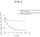
- Fig. 3 Combustion test results of the suite and tar comprising the particulates are presented in Fig. 3.
- the whole weight (mg) of the suite and tar is presented on the vertical axis and the elapsed time (h) is presented on the horizontal axis.
- the solid line represents the result obtained for the device according to the present invention, which shows the decomposing effect by spraying the catalyst, K 2 CO 3 . at 300°C. From the figure, it is understood that the weight of the suite and tar are decreasing along with the time elapse. On the other hand, the broken line represents the result obtained for the conventional device with no catalyst spray, where the reduction rate in the weight of the suite and tar is found to be low in comparison with that obtained by the device of the present invention.
- the catalyst is defined as the one at least containing one of alkali metals and alkaline earth metals, such Na and K including potassium carbonate and sodium carbonate.
- Seawater is also usable as an alkaline catalyst.
- at least one of the alkali metal or the alkaline earth metal can be contained in seawater to use as the catalyst.
- the device of the first embodiment for the present invention allows to uniformly distribute the catalyst by spraying the alkaline catalyst solution onto the surface of the captured particulates on the filter so as to cover the surface of the particulates with the alkaline catalyst solution to facilitate the absorption and carrying of the alkaline catalyst solution onto the filter, thereby allowing to make the combustion space uniform and enable the catalytic combustion at a lower temperature (300°C) than the burning temperature of higher than 400°C when using a conventional heater.
- the device of the first embodiment prevents to cause abnormal combustion happened at burning the particulates in the past and can control the combustion temperature by means of spraying the catalyst solution in away by adjusting the spraying amount and the spraying time and by adjusting the rotation speed of the filter, depending upon the combustion temperature.
- a material with excellent resistance to heat and impact for the filter 11 as the filter is repeatedly subjected to the burning and the spraying with aqueous solution.
- a heat-resisting ceramics filter or the like can be given.
- a laminated metal mesh type filter prepared by laminating metal filters onto the supporting layer for providing strength to the filter and a laminated metal unwoven cloth type filter prepared by laminating metal unwoven cloths onto the supporting layer for providing strength to the filter can be given.
- a laminated ceramics filter 34 constituted by arranging a ceramics layer 32 onto the upper side of the supporting layer 31 and a protective mesh layer 33 for protecting the ceramics layer 32 can be also used as said heat and impact-resisting filter.
- a metal catalyst such as platinum or the like, may be used for carrying it onto the filter.
- metal catalyst Other than platinum, rhodium, palladium, etc. can be used as the metal catalyst, and titanium oxide, aluminium oxide, cojulite, aluminum silica, zeolite, porous silicate, porous aluminate, and complex oxides having perovskite structure and spinel structure and the like can be given as examples for the oxide catalyst, though there is no limitation for such catalysts in the present invention.
- decomposition efficiency of the particulates may be further improved owing to combination effect of the catalytic action given by the catalyst contacting to the particulates and the catalytic action given by the alkaline catalyst attached to the particulates.
- Fig. 4(B) the mechanism and the effect of the catalyst specified in the present invention to eliminate the particulates are presented in Fig. 4(B).
- the particulates 10a contained in the exhaust gas are attached to the surface of the filter 11 at first.
- the catalyst solution 12 covers the surface of the particulates.
- the catalyst solution is penetrating into the fine pores on the particulates 10a.
- the catalyst solution having covered the surface of the particulates 10a is also dried and the component having the catalytic activity remains onto the surface of the particulates in a state being uniformly distributed.
- the catalyst solution penetrated into the inner part of the particulate is also dried, thereby allowing the component having the catalytic activity uniformly remain in the inner part of the particulate. Consequently, the catalytic reaction may take place not only on the surface of the particulates but also in the inner part of the particulates, thereby allowing complete burning of the particulates.
- the device provided in the present invention can decompose and treat the particulates contained in exhaust gas generated from motors irrespective of the type of the motors.
- non-burned portion of floating particulates (SPM) contained in exhaust gas generated from motors can be decomposed and treated at a low temperature.
- the device provided in the present invention can decompose and treat not only particulates in exhaust gas ejected from motors but also particulates contained in exhaust gas generated from various incinerators, such as urban garbage incinerators, industrial waste and sludge incinerators, thermal decomposition furnaces, fusing furnaces, etc.
- a soaking means to soak the capturing means having captured the particulates in the catalyst solution is given other than a spraying means to spray the catalyst solution onto the filter 11 having captured the particulates.
- a device for eliminating particulate in exhaust gas using a discoid-shaped filter and carrying a catalyst by using a soaking means is described.
- Fig. 5 is a schematic for showing the device for eliminating particulates in exhaust gas according to the second embodiment.
- the device for eliminating particulates contained in exhaust gas is constituted by a discoid- shaped filter 11 having the axial core in the orthogonal direction to the vertical axis, a capturing zone 22 to capture the particulates contained in the exhaust gas 10a in the flue, wherein a part of the filter 11 is rotatably set in the flue 21 for the exhaust gas, a catalyst carrying zone 25, wherein the filter 11 having captured particulates is rotated and the filter 11 is soaked in the catalyst storing tank 23 on outside the flue, and a burning zone 26, where the catalyst being carried is fed again into the flue 21 and burned at the temperature of combustion gas.
- the storing tank 27 may contain unburned carbon being attached to the surface of the filter, since the filter is soaked in the catalyst carrying zone 25.
- This soaking type device is suitable for exhaust gas treatment for overland-fixed motors, and it is required to equip a quake-preventing means to the device when applying it for motors for ships and surface transportation vehicles.
- a discoid-shaped filter as shown in Fig. 1(A), a cylinder-shaped filter as shown in Figs. 1(B) and 1(C), etc. can be given as the examples.
- Figs. 6(A) and 6(B) are schematics for showing the device for eliminating particulates contained in exhaust gas according to the third embodiment.
- the device for eliminating particulates contained in exhaust gas is constituted by a capturing means to capture the particulates being cylinder-shaped and an external direction filtration type filter 41A, whereto the particulates contained in the exhaust gas 10a are attached from outside the cylinder-shaped filter 41A, and a catalyst attaching means equipped with an ejecting nozzle 42A on the external side thereof to attach the catalyst solution onto the surface of the particulates, and sprays the catalyst solution 12 onto the surface of the filter 41A while rotating the cylinder-shaped filter 41A and then burns the unburned particulates contained in the exhaust gas after drying the sprayed filter.
- the marked number 43 represents a rotation unit to rotate the filter 41A.
- the device for eliminating particulates wherein an external direction filtration type cylinder-shaped filter 41A having the axial core in a direction orthogonal to the vertical axis direction is used and the filter 41A is rotatably set in the exhaust gas treating unit 44 by means of using a rotation unit 43, is constituted by a capturing zone 45 to capture the particulates contained in the exhaust gas 10, a catalyst carrying zone 46 to spray the catalyst solution 12 fed by the ejecting nozzle 42A from the catalyst storing tank 23 onto the rotating filter 11 having captured the particulates, a drying zone 47 to dry the carried catalyst and a burning zone 48 to burn the unburned particulate portion in combination with heat generated by the exhaust gas 10 and the catalytic effect.
- the catalyst carrying zone 46, the drying zone 47 and the burning zone 48 drawn in Fig. 6 are not the ones to be precisely specified, and these zones are expressed just as a guidepost.
- the device for eliminating particulates captures the particulates contained in the exhaust gas 10 in the particulate capturing zone 45 to the surface of the filter 41A, sprays the alkaline catalyst solution 12 in the catalyst carrying zone 46 onto the captured particulates so as to cover the surface of the particulates, dries the sprayed catalyst while rotating the filter 41A and burns the particulates in the burning zone 48, thereby allowing to decompose the unburned portion, such as suite and tar, of the particulates at a low temperature as high as 300°C and to eject the exhaust gas as clean gas 28.
- any of continuous spray, sprays at prefixed intervals and sprays depending upon the attached amount of the particulates to be detected by means of using a sensor can be employed.
- a plurality of the spray nozzles 42A may be arranged along with the axial direction of the cylinder-shaped filter 41A.
- the cylinder-shaped filter may be fixed in vertical direction by adjusting the position of rotation axis of the filter to the vertical axis to make the spray flow from the nozzle 41A downdraft and to reduce the number of the nozzles to be set.
- the device may be prepared in a type of soaking filter as shown in Fig. 9.
- Such soaking type may be suitable for the device of which filter 61 has a cross section in convexo-concave form comprising the convexo 61a and the concave 61b as shown in Fig. 10 and the device comprising a filter in a complex shape, such as small cylinder in group type filter 63, wherein a plurality of gas-permeable cylinders 41a are vertically set on the surface of a cylindrical tube 62 as shown in Fig. 11.
- Figs. 12(A) and 12(B) are schematics for showing the device for eliminating particulates contained in exhaust gas according to the fourth embodiment.
- the device for eliminating particulates contained in exhaust gas is equipped with a capturing means to capture the particulates being an internal filtration type cylinder-shaped filter 41B, ejects the particulates contained in the exhaust gas 10 from the internal side of the cylinder-shaped filter 41B via the gas ejecting tube 50, having therein an ejecting nozzle 42B for the catalyst attaching means to attach the catalyst solution onto the surface of the particulates, sprays the catalyst solution 12 onto the surface of the filter 41B while rotating the cylinder-shaped filter 41B and then burns the unburned particulates in the exhaust gas following to drying the sprayed catalyst.
- a capturing means to capture the particulates being an internal filtration type cylinder-shaped filter 41B
- ejects the particulates contained in the exhaust gas 10 from the internal side of the cylinder-shaped filter 41B via the gas ejecting tube 50, having therein an ejecting nozzle 42B for the catalyst attaching means to attach the catalyst solution onto the surface of the particulates,
- the device for eliminating particulates wherein an internal direction filtration type cylinder-shaped filter 41B having the axial core in a direction orthogonal to the vertical axis direction is used and the filter 41B is rotatably set in the exhaust gas treating unit 44 by means of using a rotation unit 43, is constituted by a capturing zone 45 to capture the particulates contained in the exhaust gas 10, a catalyst carrying zone 46 to spray the catalyst solution 12 fed by the ejecting nozzle 42A from the catalyst storing tank 23 onto the rotating filter 11 having captured the particulates, a drying zone 47 to dry the carried catalyst and a burning zone 48 to burn the unburned particulate portion in combination with heat generated by the exhaust gas 10 and the catalytic effect.
- the device for eliminating particulates captures the particulates contained in the exhaust gas 10 in the particulate capturing zone 45 to the surface of the filter 41B, sprays the alkaline catalyst solution 12 in the catalyst carrying zone 46 onto the captured particulates so as to cover the surface of the particulates, dries the sprayed catalyst while rotating the filter 41B and burns the particulates in the burning zone 48, thereby allowing to decompose the unburned portion, such as suite and tar, of the particulates at a low temperature as high as 300°C and to eject the exhaust gas as clean gas 28.
- thedevice for eliminating particulates contained in exhaust gas uses a fixed filter, which is different from the one using a rotatable filter, and performs the carrying of a catalyst by using a spraying means.
- Fig. 13 is a schematic for showing the device for eliminating particulates contained in exhaust gas according to the present embodiment.
- the device for eliminating particulates contained in exhaust gas has a capturing means to capture the particulates which is a fixed pier-shaped filter 71, attaches the particulates in the exhaust gas 10 onto the outside of the filter 71, has a catalyst attaching means equipped with four spray nozzles 2 A-D on the exterior circumference of the catalyst attaching means to attach the catalyst solution 12 onto the surface of the particulates and burns the unburned particulates in the exhaust gas following to drying of the catalyst.
- the pier-shaped filter is used for the fixed filter in the present embodiment, there is no limitation in the shape to be used.
- a cylinder-shaped and a polygon-shaped filter are also usable, which may be sprayed with the catalyst solution 12 in turn while switching the exhaust gas to be covered.
- the device for eliminating particulates contained in exhaust gas using a fixed filter and performing the carrying of a catalyst by using the spraying means is provided.
- Fig. 14 is a schematic for showing the device for eliminating particulates contained in exhaust gas according to the sixth embodiment.
- the device for eliminating particulates contained in exhaust gas has a capturing means to capture the particulates which is a fixed pier-shaped filter 81, attaches the particulates in the exhaust gas 10 onto the outside of the filter 81, sprays the catalyst solution 12 onto the surface of the particulates being captured on the filter 81 by using the spraying nozzle (not shown in Fig.) and burns the unburned particulates portion in the exhaust gas following to drying of the sprayed catalyst.
- the filter 81 to capture the particulates in the present embodiment is a honeycomb-shaped filter having a checkered pattern on the end surface thereof, which is constituted by alternatively closing the end with a choke 82.
- a method to attach the catalyst it is not limited to said spraying method, and any methods capable of appropriately carrying the catalyst onto the filter, such as a method to soak the internal part of the filter with the catalyst solution, may be employed without limitation.
- the device for eliminating particulates contained in exhaust gas using a fixed filter and performing the carrying of a catalyst by using a spraying means is provided.
- Fig. 15 is a schematic for showing the device for eliminating particulates contained in exhaust gas according to the seventh embodiment.
- the device for eliminating particulates contained in exhaust gas has a capturing means to capture the particulates which is a laminated filter 91 having a canaliform structure by folding a plate-shaped filter, attaches the particulates in the exhaust gas 10 onto the surface of the filter 91, sprays the catalyst solution 12 onto the surface of the particulates being captured on the filter 91 by using spraying nozzles (not shown in Fig.) and burns the unburned particulates portion in the exhaust gas following to drying of the sprayed catalyst.
- the marked number 92 represents a choke.
- the laminated type filter 91 may be constituted by laminating plate -shaped filters in multilayer and alternatively closing the both end sides with chokes 92.
- the unburned particulates attached to the surface of the filter can be cleaned up and eliminated easily.
- the device for eliminating particulates contained in exhaust gas using a fixed filter and performing the carrying of a catalyst by using a spraying means is provided.
- Fig. 16 is a schematic for showing the device for eliminating particulates contained in exhaust gas according to the eighth embodiment.
- the device for eliminating particulates contained in exhaust gas has a capturing means to capture the particulates which is a filter 95 constituted by setting a plurality of doughnut-shaped discoid filters in hollow 93 in the internal cylinder 94, attaches the particulates in the exhaust gas 10 onto the surface of the filter 91, sprays the catalyst solution 12 onto the surface of the particulates being captured on the filter 91 by using spraying nozzles (not shown in Fig.) and burns the unburned particulates in the exhaust gas following to drying of the sprayed catalyst.
- a capturing means to capture the particulates which is a filter 95 constituted by setting a plurality of doughnut-shaped discoid filters in hollow 93 in the internal cylinder 94, attaches the particulates in the exhaust gas 10 onto the surface of the filter 91, sprays the catalyst solution 12 onto the surface of the particulates being captured on the filter 91 by using spraying nozzles (not shown in Fig.) and burns the unburne
- discoid-shaped and cylinder-shaped filters or fixed type filter are exemplified above as the filter apparatus to be used in this embodiment, there is no limitation for the filters, and any types of filters which can efficiently capture the particulates contained in exhaust gas may be used.
- Fig. 17(A) shows an independent and either rotating or fixed type filter being in a cylindrical shape.
- Fig. 17(B) shows a filter system constituted by three filters arranged in parallel by means of tubing to perform absorption of the particulates onto the filter, drying of the filter and burning of the particulates in turn by switching the filters to be used from one to another.
- Fig. 17(C) shows an unit type filter comprising a plurality of filters.
- Fig. 18 is a schematic for showing the exhaust gas cleaning up system according to the present embodiment.
- the exhaust gas cleaning up system of this embodiment is a system to clean up exhaust gas ejected from motors and is constituted by mounting a particulate eliminating device 102, which is located in the exhaust gas feeding path from motors, large diesel engines 101 for ships, to decompose and treat floating particulates contained in the exhaust gas 10 and a denitification device 103 equipped at the downstream side of the particulate eliminating device 102 to eliminate the particulates and hazardous substance, such as nitrogen oxide, thereby allowing to eject clean gas 104 from a chimney 105.
- a particulate eliminating device 102 which is located in the exhaust gas feeding path from motors, large diesel engines 101 for ships, to decompose and treat floating particulates contained in the exhaust gas 10 and a denitification device 103 equipped at the downstream side of the particulate eliminating device 102 to eliminate the particulates and hazardous substance, such as nitrogen oxide, thereby allowing to eject clean gas 104 from a chimney 105.
- Fig. 19 is a schematic for showing the exhaust gas cleaning up system according to the tenth embodiment for the present invention.
- the exhaust gas cleaning up system of the present embodiment is a system to clean up the exhaust gas ejected from motors and is constituted by mounting a particulate eliminating device 102, which is located in the exhaust gas feeding path from motors, large diesel engines 101 for ships, to decompose and treat floating particulates contained in the exhaust gas 10, and the system is constituted as an exhaust gas recycling system (EGR) to recycles and circulates the part of the exhaust gas, approximately 30% more or less, which is ejected from an engine 101 to a diesel engine 101.
- EGR exhaust gas recycling system
- this system of the present embodiment allows to eject clean exhaust gas from which particulates have been eliminated, thereby allowing to reduce the amount of nitrogen oxides in total produced in exhaust gas over a long time.
- the present system is suitably applied for diesel engines to be used for surface transport vehicles other than for ships.
- Fig. 20 is a schematic for showing the exhaust gas cleaning up system according to the eleventh embodiment.
- the exhaust gas cleaning up system of this embodiment is a system to clean up exhaust gas ejected from motors, such as motors for surface transportation vehicles including motortrucks, buses, roller cars, folklifts and shoveling cars and overland-fixed motors including compressors and generators, and is constituted by mounting a particulate eliminating device 102, which is located in the exhaust gas feeding path from a diesel engines 101 as a motor, to decompose and treat floating particulates contained in the exhaust gas 10 and a denitification device 103 equipped at the downstream side of the particulate eliminating device 102 to eliminate the particulates and hazardous substance, such as nitrogen oxide, thereby allowing to eject clean gas 104 to the outdoor.
- motors such as motors for surface transportation vehicles including motortrucks, buses, roller cars, folklifts and shoveling cars and overland-fixed motors including compressors and generators
- a particulate eliminating device 102 which is located in the exhaust gas feeding path from a diesel engines 101 as a motor, to decompose and treat
- Fig. 21 is a schematic for showing the exhaust gas cleaning up system according to the twelfth embodiment.
- the exhaust gas cleaning up system of this embodiment is corresponding to the cogeneration system and is constituted by mounting a particulate eliminating device 102, which is located in the exhaust gas feeding path from a diesel engine generator 111 outputting electricity.
- a denitification device 103 is equipped at the downstream side of the particulate eliminating device 102 to eliminate the particulates and hazardous substance, such as nitrogen oxide, thereby allowing to eject clean gas 104 to the outdoor.
- the system recovers heat as hot water by using a heat-recovering boiler 112 at ejecting the clean gas 104 and is aiming at improving energy utilization efficiency.
- the system according to the present embodiment enables to constitute a system capable of decomposing and treating the unburned portion of the floating particulates (SPM) contained in the exhaust gas ejected from motors, such as diesel engines for ships, surface transportation vehicles and overland fixed use, at a low temperature.
- SPM floating particulates
- Fig. 22 is a schematic for showing the exhaust gas cleaning up system according to the thirteenth embodiment.
- the exhaust gas cleaning up system is a system to clean up exhaust gas ejected from a gasification furnace and is constituted with a particulate eliminating device 102, which is mounted in the smoke feeding path from the gasification furnace 121, to decompose and treat the floating particulates contained in the exhaust gas 10 and a denitrification device 103 equipped at the downstream side of the particulate eliminating device 102, thereby eliminating the particulates and hazardous substance, such as nitrogen oxides, to eject cleaned up gas 104 through a chimney 105.
- a particulate eliminating device 102 which is mounted in the smoke feeding path from the gasification furnace 121, to decompose and treat the floating particulates contained in the exhaust gas 10 and a denitrification device 103 equipped at the downstream side of the particulate eliminating device 102, thereby eliminating the particulates and hazardous substance, such as nitrogen oxides, to eject cleaned up gas 104 through a chimney 105.
- the exhaust gas cleaning up system allows to decompose and eliminate particulates contained in exhaust gas ejected not only from motors but also from various incinerators, such as urban garbage incinerators, industrial waste incinerators and sludge incinerators, thermal decomposition furnaces, fusion furnaces, etc.
Abstract
Description
Fig. 2 is a schematic for the device to eliminate particulates in exhaust gas according to the first embodiment.
On the other hand, the broken line represents the result obtained for the conventional device with no catalyst spray, where the reduction rate in the weight of the suite and tar is found to be low in comparison with that obtained by the device of the present invention.
Claims (24)
- A device for eliminating particulates contained in exhaust gas, characterized in that the device is constituted by a capturing means to capture the particulates and a catalyst attaching means to attach catalyst solution onto the surface of the particulates captured by the capturing means, and burns and decomposes the captured particulates.
- A device for eliminating the particulates contained in exhaust gas to eliminate the particulates in exhaust gas ejected from a motor, characterized in that the device is constituted by a capturing means to capture the particulates and a catalyst attaching means to attach catalyst solution onto the surface of the particulates captured by the capturing means, and burns and decomposes the captured particulates.
- The device for eliminating particulates contained in exhaust gas according to the claim 1, wherein the catalyst attaching means to attach the catalyst solution onto the surface of the particulates is characterized by being equipped with a spraying means to spray the catalyst solution to the capturing means by which the particulates are captured.
- The device for eliminating the particulates in exhaust gas according to the claim 1, wherein the catalyst attaching means to attach the catalyst solution onto the surface of the particulates is a soaking means to soak the capturing means having captured the particulates into the catalyst solution.
- The device for eliminating the particulates in exhaust gas according to claim 1, wherein the catalyst solution is any of a catalyst solution containing at least one of alkali metals and alkaline earth metals, seawater, and seawater containing at least one of the alkali metals and the alkaline earth metals.
- The device for eliminating the particulates in exhaust gas according to the claim 1, wherein the catalyst is carried onto the capturing means.
- The device for eliminating the particulates in exhaust gas according to any of the claims 1 through 6, wherein the capturing means to capture the particulates is either a discoid-shaped filter or a cylinder-shaped filter.
- The device for eliminating particulates in exhaust gas according to the claim 7, wherein the filter is either an internal direction filtration type to flow out the exhaust gas introduced into the inside of the filter or an external direction filtration type to vent the exhaust gas being introduced into the exterior of the filter into the inside of the filter.
- The device for eliminating particulates in exhaust gas according to the claim 8,wherein the filter has a laminated structure having a supporting layer to hold the strength of the filter and a capturing layer to capture the laminated particulates onto the supporting layer.
- The device for eliminating particulates in exhaust gas according to the claim 9, wherein a protective layer for the particulates is provided onto the capturing layer.
- The device for eliminating particulates in exhaust gas according to the claim 7, wherein the cross section of the filter assumes a convexo-concave shape.
- The device for eliminating particulates in exhaust gas according to the claim 7, wherein a plurality of cylinder-shaped filters are set in standing state onto the surface of the filter.
- The device for eliminating particulates in exhaust gas according to the claim 7, wherein the capturing means to capture the particulates is a discoid-shaped filter, and the catalyst attaching means to attach the catalyst solution onto the surface of the particulates is set at the surface side of the discoid-shaped filter, characterized in that the device rotates the discoid-shaped filter, then sprays the catalyst solution onto the surface of the filter at the different positions on the same side of the surface of the discoid-shaped filter, and burns the particulates having been not burned in the exhaust gas following to drying of the said filter to eliminate the particulates.
- The device for eliminating particulates in exhaust gas according to the claim 7, wherein the capturing means to capture the particulates is a cylinder-shaped filter, the catalyst attaching means to attach the particulates in the exhaust gas from either side of the inside or the outside of the cylinder-shaped filter and to attach the catalyst solution onto the surface of the particulates is set to the interior side of the lateral side of the cylinder-shaped filter in case of the internal direction filtration type or is set to the exterior side of the lateral side of the cylinder-shaped filter in case of the external direction filtration type, and characterized in that the device sprays the catalyst solution onto the surface of the filter while rotating the cylinder-shaped filter and burns the particulates having been not burned in the exhaust gas following to drying of the sprayed filter to eliminate the particulates.
- The device for eliminating particulates in exhaust gas according to the claim 7, wherein the capturing means to capture the particulates is a cylinder-shaped filter, and at least the two catalyst attaching means to attach the particulates in the exhaust gas from the outside of either the cylinder-shaped filter or the polygon-shaped filter and to attach the catalyst solution onto the surface of the particulates are arranged in the circumferential direction of the filter, characterized in that the device sprays the catalyst solution from the surrounding of the filter onto the surface of the filter while switching the catalyst attaching means and burns the particulates having been not burned in the exhaust gas following to drying of the sprayed filter.
- The device for eliminating particulates in exhaust gas according to the claim 7, wherein the capturing means to capture the particulates is a honeycomb-shaped filter provided with a choke of which end surface being checked pattern, characterized in that the device attaches the particulates in the exhaust gas onto the surface of the filter, sprays the catalyst solution onto the surface of the particulates and then burns the particulates having been not burned in the exhaust gas following to drying of the sprayed filter.
- The device for eliminating particulates in exhaust gas according to the claim 7, wherein the capturing means to capture the particulates is a laminated type filter being constituted by laminated plate-shaped filters of which end parts are alternatively choked, characterized in that the device attaches the particulates in the exhaust gas onto the surface of the filter, sprays the catalyst solution onto the surface of the particulates and then burns the particulates in the exhaust gas having been not burned following to drying of the sprayed filter.
- The device for eliminating particulates in exhaust gas according to the claim 7, wherein the capturing means to capture the particulates is a laminated type filter constituted by folding plate-shaped filters, characterized in that the device attaches the particulates in the exhaust gas onto the surface of the filter, sprays the catalyst solution onto the surface of the particulates and then burns the particulates having been not burned in the exhaust gas following to drying of the sprayed filter.
- The device for eliminating particulates in exhaust gas according to the claim 7, wherein the capturing means to capture the particulates is constituted by arranging a plurality of doughnut-shaped, fistulous and discoid filters in parallel, characterized in that the device attaches the particulates in the exhaust gas onto the surface of the filter, sprays the catalyst solution onto the surface of the particulates and then burns the particulates having been not burned in the exhaust gas following to drying of the sprayed filter.
- A process for eliminating particulates in exhaust gas, characterized in that the process is constituted by a step to capture the particulates, a step to attach a catalyst solution onto the surface of the captured particulates and a step to burn and decompose the particulates.
- The process to eliminate particulates in exhaust gas according to claim 20, characterized in that the process is constituted by a step to spray the catalyst solution onto the surface of the particulates being attached onto the surface of the capturing means and a step to attach the catalyst solution onto the surface of the captured particulates.
- The process to eliminate particulates in exhaust gas according to the claim 20, characterized in that the process is constituted by a step to soak the capturing means whereto the particulates having been attached onto the surface thereof into the catalyst solution and a step to attach the catalyst solution onto the surface of the captured particulates.
- A exhaust gas treating system to clean up the exhaust gas, characterized in that the system is set onto the flue for the exhaust gas andhas the particulate eliminating device according to any of the claims 1 through 19 to decompose and treat the floating particulates in the exhaust gas.
- The exhaust gas treating system to clean up the exhaust gas according to the claim 23 , characterized by having a denitrification device to decompose and treat nitrogen oxides in the exhaust gas at the downstream side of the particulate eliminating device.
Applications Claiming Priority (2)
| Application Number | Priority Date | Filing Date | Title |
|---|---|---|---|
| JP35871899A JP3258646B2 (en) | 1999-12-17 | 1999-12-17 | Apparatus and method for removing fine particles in exhaust gas |
| JP35871899 | 1999-12-17 |
Publications (2)
| Publication Number | Publication Date |
|---|---|
| EP1108460A1 true EP1108460A1 (en) | 2001-06-20 |
| EP1108460B1 EP1108460B1 (en) | 2006-10-11 |
Family
ID=18460761
Family Applications (1)
| Application Number | Title | Priority Date | Filing Date |
|---|---|---|---|
| EP00126852A Expired - Lifetime EP1108460B1 (en) | 1999-12-17 | 2000-12-07 | Process for eliminating particulates in exhaust gas |
Country Status (9)
| Country | Link |
|---|---|
| US (1) | US6631612B1 (en) |
| EP (1) | EP1108460B1 (en) |
| JP (1) | JP3258646B2 (en) |
| KR (1) | KR100418229B1 (en) |
| CN (1) | CN1119196C (en) |
| AT (1) | ATE342120T1 (en) |
| DE (1) | DE60031227T8 (en) |
| DK (1) | DK1108460T3 (en) |
| NO (1) | NO324435B1 (en) |
Cited By (4)
| Publication number | Priority date | Publication date | Assignee | Title |
|---|---|---|---|---|
| WO2003011437A1 (en) * | 2001-08-01 | 2003-02-13 | Johnson Matthey Public Limited Company | Gasoline engine with an exhaust system for combusting particulate matter |
| US7832203B2 (en) | 2001-10-27 | 2010-11-16 | Johnson Matthey Public Limited Company | Exhaust system for a lean burn internal combustion engine |
| WO2010073008A3 (en) * | 2008-12-22 | 2011-04-14 | Pyropure Limited | Processing of off-gas from waste treatment |
| US9387438B2 (en) | 2014-02-14 | 2016-07-12 | Tenneco Automotive Operating Company Inc. | Modular system for reduction of sulphur oxides in exhaust |
Families Citing this family (20)
| Publication number | Priority date | Publication date | Assignee | Title |
|---|---|---|---|---|
| JP4506928B2 (en) * | 2001-09-20 | 2010-07-21 | 三菱自動車工業株式会社 | Exhaust purification device |
| EP1736225A3 (en) * | 2003-06-10 | 2007-01-17 | Ibiden Co., Ltd. | Honeycomb structural body |
| JP4827530B2 (en) * | 2003-07-15 | 2011-11-30 | イビデン株式会社 | Honeycomb structure |
| FR2858355B1 (en) * | 2003-07-31 | 2005-10-28 | Peugeot Citroen Automobiles Sa | METHOD AND DEVICE FOR DEPOLLUTING THE EXHAUST GASES OF AN INTERNAL COMBUSTION ENGINE |
| US7964026B2 (en) * | 2003-08-04 | 2011-06-21 | Power Reclamation, Inc. | Gasification apparatus |
| DE10349632B4 (en) * | 2003-10-24 | 2017-05-24 | Robert Bosch Gmbh | Apparatus for filtering a gas flowing through a conduit |
| FR2892127B1 (en) * | 2005-10-14 | 2012-10-19 | Commissariat Energie Atomique | DEVICE FOR GASIFYING BIOMASS AND ORGANIC WASTE AT HIGH TEMPERATURE AND WITH EXTERNAL ENERGY DELIVERY FOR THE GENERATION OF A HIGH-QUALITY SYNTHESIS GAS |
| US20080078171A1 (en) * | 2006-09-29 | 2008-04-03 | Dacosta Herbert F M | Chemically functionalized filter system |
| US8356475B2 (en) | 2007-02-01 | 2013-01-22 | University Of Notre Dame Du Lac | Catalysts with slow, passive release of alkali ions |
| US8091337B2 (en) * | 2008-02-29 | 2012-01-10 | Corning Incorporated | Exhaust treatment device having a reactive compound and conditioning the device via endothermic reaction |
| JP2011148399A (en) * | 2010-01-21 | 2011-08-04 | Mitsubishi Heavy Ind Ltd | Ship and method for operating ship |
| DE102011012266A1 (en) * | 2011-02-22 | 2012-08-23 | Rauschert Kloster Veilsdorf Gmbh | Device for cleaning an exhaust gas stream |
| US9592490B2 (en) | 2011-11-30 | 2017-03-14 | University Of Notre Dame Du Lac | Glass catalysts for soot combustion and methods of manufacturing the same |
| CN102536392B (en) * | 2012-02-10 | 2013-08-07 | 徐和平 | Diesel engine exhaust purifier with rotary regeneration device |
| CN103272457A (en) * | 2013-06-14 | 2013-09-04 | 上海雄坤环境科技有限公司 | Indoor air purification device and method |
| CN103334817B (en) * | 2013-07-02 | 2016-03-02 | 武汉纺织大学 | A kind of diesel engine exhaust gas purification device |
| CN105804835B (en) * | 2014-12-31 | 2018-11-27 | 骆旭东 | Environmentally friendly dynamic particle trapper |
| KR102076915B1 (en) * | 2018-10-17 | 2020-02-12 | 한국조선해양 주식회사 | Fluidized Catalystic Response System with Regeneration Function |
| CN114033530B (en) * | 2021-11-09 | 2024-01-30 | 宁波开特环保科技有限公司 | Be applied to environment-friendly automobile's discharging equipment |
| CN115680825B (en) * | 2022-11-03 | 2023-07-18 | 江苏润沃达环境科技有限公司 | Diesel engine automobile tail gas purifying device and purifying method thereof |
Citations (5)
| Publication number | Priority date | Publication date | Assignee | Title |
|---|---|---|---|---|
| US4631076A (en) * | 1983-11-30 | 1986-12-23 | Tokyo Roki Co., Ltd. | Apparatus for removing carbon particles from exhaust gas from internal combustion engine |
| WO1997028358A1 (en) * | 1996-01-31 | 1997-08-07 | Clean Diesel Technologies, Inc. | Method and apparatus for reducing harmful emissions from a diesel engine by post combustion catalyst injection |
| US5820836A (en) * | 1994-12-26 | 1998-10-13 | Institute Francais Du Petrole | Rotating catalytic cleaning device for polluted effluents |
| US5912190A (en) * | 1995-04-24 | 1999-06-15 | The Associated Octel Company Limited | Synergistic process for improving combustion |
| US5967771A (en) * | 1997-04-01 | 1999-10-19 | Engelhard Corporation | Rotary regenerative oxidizer |
Family Cites Families (16)
| Publication number | Priority date | Publication date | Assignee | Title |
|---|---|---|---|---|
| US3289397A (en) * | 1964-03-31 | 1966-12-06 | Gen Dynamics Corp | Aerosol filter |
| US3763631A (en) * | 1971-06-01 | 1973-10-09 | Chemical Detergents Coinc | Method and apparatus for removing entrained matter from centrifugal filter media |
| US4276066A (en) * | 1980-02-25 | 1981-06-30 | General Motors Corporation | Monolith diesel exhaust filter with self-regeneration |
| AU540009B2 (en) * | 1982-02-16 | 1984-10-25 | Matsushita Electric Industrial Co., Ltd. | Exhaust gas filter |
| US4415344A (en) * | 1982-03-01 | 1983-11-15 | Corning Glass Works | Diesel particulate filters for use with smaller diesel engines |
| US4641496A (en) * | 1984-12-17 | 1987-02-10 | Ford Motor Company | Continuous rotary regeneration system for a particulate trap |
| US4573317A (en) * | 1985-03-11 | 1986-03-04 | General Motors Corporation | Diesel exhaust cleaner and regeneration burner system with indexing particulate trap |
| US4710520A (en) * | 1986-05-02 | 1987-12-01 | Max Klein | Mica-polymer micro-bits composition and process |
| US4869738A (en) * | 1987-08-26 | 1989-09-26 | W. R. Grace & Co.-Conn. | Particulate trap |
| DE68919505T2 (en) * | 1988-04-08 | 1995-06-22 | Mitsubishi Heavy Ind Ltd | Catalyst filter, method for producing a catalyst filter and method for treating combustion gases with a catalyst filter. |
| US5013340A (en) * | 1989-06-29 | 1991-05-07 | Northeastern University | Rotating diesel particulate trap |
| US5322671A (en) * | 1992-02-25 | 1994-06-21 | Blue Planet Technologies Co., L.P. | Catalytic vessel |
| NZ251022A (en) * | 1992-02-25 | 1996-09-25 | Blue Planet Technologies Co Lp | Catalytic system, for (automotive) combustion system |
| US5655212A (en) * | 1993-03-12 | 1997-08-05 | Micropyretics Heaters International, Inc. | Porous membranes |
| US5451558A (en) * | 1994-02-04 | 1995-09-19 | Goal Line Environmental Technologies | Process for the reaction and absorption of gaseous air pollutants, apparatus therefor and method of making the same |
| US6253543B1 (en) * | 1999-08-24 | 2001-07-03 | Ford Global Technologies, Inc. | Lean catalyst and particulate filter control |
-
1999
- 1999-12-17 JP JP35871899A patent/JP3258646B2/en not_active Expired - Fee Related
-
2000
- 2000-08-23 KR KR10-2000-0048814A patent/KR100418229B1/en not_active IP Right Cessation
- 2000-12-07 EP EP00126852A patent/EP1108460B1/en not_active Expired - Lifetime
- 2000-12-07 DK DK00126852T patent/DK1108460T3/en active
- 2000-12-07 AT AT00126852T patent/ATE342120T1/en not_active IP Right Cessation
- 2000-12-07 DE DE60031227T patent/DE60031227T8/en not_active Expired - Fee Related
- 2000-12-15 US US09/736,255 patent/US6631612B1/en not_active Expired - Fee Related
- 2000-12-15 NO NO20006414A patent/NO324435B1/en not_active IP Right Cessation
- 2000-12-17 CN CN00126794A patent/CN1119196C/en not_active Expired - Fee Related
Patent Citations (5)
| Publication number | Priority date | Publication date | Assignee | Title |
|---|---|---|---|---|
| US4631076A (en) * | 1983-11-30 | 1986-12-23 | Tokyo Roki Co., Ltd. | Apparatus for removing carbon particles from exhaust gas from internal combustion engine |
| US5820836A (en) * | 1994-12-26 | 1998-10-13 | Institute Francais Du Petrole | Rotating catalytic cleaning device for polluted effluents |
| US5912190A (en) * | 1995-04-24 | 1999-06-15 | The Associated Octel Company Limited | Synergistic process for improving combustion |
| WO1997028358A1 (en) * | 1996-01-31 | 1997-08-07 | Clean Diesel Technologies, Inc. | Method and apparatus for reducing harmful emissions from a diesel engine by post combustion catalyst injection |
| US5967771A (en) * | 1997-04-01 | 1999-10-19 | Engelhard Corporation | Rotary regenerative oxidizer |
Cited By (8)
| Publication number | Priority date | Publication date | Assignee | Title |
|---|---|---|---|---|
| WO2003011437A1 (en) * | 2001-08-01 | 2003-02-13 | Johnson Matthey Public Limited Company | Gasoline engine with an exhaust system for combusting particulate matter |
| US7832203B2 (en) | 2001-10-27 | 2010-11-16 | Johnson Matthey Public Limited Company | Exhaust system for a lean burn internal combustion engine |
| WO2010073008A3 (en) * | 2008-12-22 | 2011-04-14 | Pyropure Limited | Processing of off-gas from waste treatment |
| GB2478238A (en) * | 2008-12-22 | 2011-08-31 | Pyropure Ltd | Processing of off-gas from waste treatment |
| GB2478238B (en) * | 2008-12-22 | 2012-05-16 | Pyropure Ltd | Processing of off-gas from waste treatment |
| US9623372B2 (en) | 2008-12-22 | 2017-04-18 | Pyropure Limited | Processing of off-gas from waste treatment |
| US9925491B2 (en) | 2008-12-22 | 2018-03-27 | Pyropure Limited | Processing of off-gas from waste treatment |
| US9387438B2 (en) | 2014-02-14 | 2016-07-12 | Tenneco Automotive Operating Company Inc. | Modular system for reduction of sulphur oxides in exhaust |
Also Published As
| Publication number | Publication date |
|---|---|
| DE60031227T2 (en) | 2007-08-23 |
| ATE342120T1 (en) | 2006-11-15 |
| CN1119196C (en) | 2003-08-27 |
| KR20010067095A (en) | 2001-07-12 |
| NO324435B1 (en) | 2007-10-15 |
| DK1108460T3 (en) | 2007-02-19 |
| JP3258646B2 (en) | 2002-02-18 |
| DE60031227D1 (en) | 2006-11-23 |
| JP2001173426A (en) | 2001-06-26 |
| US6631612B1 (en) | 2003-10-14 |
| CN1302945A (en) | 2001-07-11 |
| KR100418229B1 (en) | 2004-02-11 |
| DE60031227T8 (en) | 2007-12-27 |
| EP1108460B1 (en) | 2006-10-11 |
| US20010010153A1 (en) | 2001-08-02 |
| NO20006414D0 (en) | 2000-12-15 |
| NO20006414L (en) | 2001-06-18 |
Similar Documents
| Publication | Publication Date | Title |
|---|---|---|
| US6631612B1 (en) | Device for eliminating particulates in exhaust gas and method for eliminating the particulates | |
| EP1877162B1 (en) | Process for purifying exhaust gases and apparatus for purifying exhaust gases | |
| CN104583547A (en) | Exhaust component mounting system | |
| PL133095B1 (en) | Apparatus for catalytically purifying exhaust gases from diesel engines | |
| EP2444606A1 (en) | Exhaust gas treatment device for diesel engine | |
| JP3573708B2 (en) | Diesel particulate removal equipment | |
| CN107737527A (en) | Marine exhaust dedusting denitrification integral system | |
| JP4251764B2 (en) | Exhaust gas purification device and exhaust gas purification method using the same | |
| CN105587381A (en) | Tail gas purifying and silencing device for engine | |
| JP2001227332A (en) | Exhaust gas denitrification system for ship | |
| KR100923024B1 (en) | Catalyst coating method for candle type ceramic filter | |
| EP1101907A1 (en) | Exhaust gas emission-control system | |
| JP2002339731A (en) | Method and device for treatment of engine exhaust emission | |
| JP4301702B2 (en) | Apparatus and method for removing suspended particulate matter in exhaust gas | |
| JP2002045653A (en) | Device for removing suspended particulate in exhaust gas and method for removing the same | |
| CN114191958A (en) | Multi-pollutant cooperative advanced treatment system for hazardous waste incineration flue gas | |
| JPH04301114A (en) | Filter for cleaning exhaust gas of internal combustion engine | |
| JP2004105843A (en) | Method of treating harmful substance in exhaust gas | |
| CN217785164U (en) | A exhaust purification is discharged and is kept away subassembly for coating production | |
| JP2002336628A (en) | Apparatus for removing suspended particles in exhaust gas | |
| JPH04301129A (en) | Filter for cleaning exhaust gas of internal combustion engine | |
| CN211799499U (en) | Waste incinerator flue gas filter equipment | |
| JP2001227324A (en) | Exhaust recirculating system furnished with particulate removal device | |
| JP3238982B2 (en) | Dust removal device for diesel engine | |
| JP4499581B2 (en) | Exhaust gas purification apparatus and method |
Legal Events
| Date | Code | Title | Description |
|---|---|---|---|
| PUAI | Public reference made under article 153(3) epc to a published international application that has entered the european phase |
Free format text: ORIGINAL CODE: 0009012 |
|
| 17P | Request for examination filed |
Effective date: 20001207 |
|
| AK | Designated contracting states |
Kind code of ref document: A1 Designated state(s): AT BE CH CY DE DK ES FI FR GB GR IE IT LI LU MC NL PT SE TR |
|
| AX | Request for extension of the european patent |
Free format text: AL;LT;LV;MK;RO;SI |
|
| AKX | Designation fees paid |
Free format text: AT BE CH CY DE DK ES FI FR GB GR IE IT LI LU MC NL PT SE TR |
|
| 17Q | First examination report despatched |
Effective date: 20020214 |
|
| GRAP | Despatch of communication of intention to grant a patent |
Free format text: ORIGINAL CODE: EPIDOSNIGR1 |
|
| RTI1 | Title (correction) |
Free format text: PROCESS FOR ELIMINATING PARTICULATES IN EXHAUST GAS |
|
| GRAS | Grant fee paid |
Free format text: ORIGINAL CODE: EPIDOSNIGR3 |
|
| GRAA | (expected) grant |
Free format text: ORIGINAL CODE: 0009210 |
|
| AK | Designated contracting states |
Kind code of ref document: B1 Designated state(s): AT BE CH CY DE DK ES FI FR GB GR IE IT LI LU MC NL PT SE TR |
|
| PG25 | Lapsed in a contracting state [announced via postgrant information from national office to epo] |
Ref country code: AT Free format text: LAPSE BECAUSE OF FAILURE TO SUBMIT A TRANSLATION OF THE DESCRIPTION OR TO PAY THE FEE WITHIN THE PRESCRIBED TIME-LIMIT Effective date: 20061011 Ref country code: LI Free format text: LAPSE BECAUSE OF FAILURE TO SUBMIT A TRANSLATION OF THE DESCRIPTION OR TO PAY THE FEE WITHIN THE PRESCRIBED TIME-LIMIT Effective date: 20061011 Ref country code: CH Free format text: LAPSE BECAUSE OF FAILURE TO SUBMIT A TRANSLATION OF THE DESCRIPTION OR TO PAY THE FEE WITHIN THE PRESCRIBED TIME-LIMIT Effective date: 20061011 Ref country code: BE Free format text: LAPSE BECAUSE OF FAILURE TO SUBMIT A TRANSLATION OF THE DESCRIPTION OR TO PAY THE FEE WITHIN THE PRESCRIBED TIME-LIMIT Effective date: 20061011 |
|
| REG | Reference to a national code |
Ref country code: GB Ref legal event code: FG4D |
|
| REG | Reference to a national code |
Ref country code: CH Ref legal event code: EP |
|
| REG | Reference to a national code |
Ref country code: IE Ref legal event code: FG4D |
|
| REF | Corresponds to: |
Ref document number: 60031227 Country of ref document: DE Date of ref document: 20061123 Kind code of ref document: P |
|
| PG25 | Lapsed in a contracting state [announced via postgrant information from national office to epo] |
Ref country code: IE Free format text: LAPSE BECAUSE OF NON-PAYMENT OF DUE FEES Effective date: 20061207 |
|
| PG25 | Lapsed in a contracting state [announced via postgrant information from national office to epo] |
Ref country code: MC Free format text: LAPSE BECAUSE OF NON-PAYMENT OF DUE FEES Effective date: 20061231 |
|
| PG25 | Lapsed in a contracting state [announced via postgrant information from national office to epo] |
Ref country code: ES Free format text: LAPSE BECAUSE OF FAILURE TO SUBMIT A TRANSLATION OF THE DESCRIPTION OR TO PAY THE FEE WITHIN THE PRESCRIBED TIME-LIMIT Effective date: 20070122 |
|
| REG | Reference to a national code |
Ref country code: SE Ref legal event code: TRGR |
|
| PG25 | Lapsed in a contracting state [announced via postgrant information from national office to epo] |
Ref country code: PT Free format text: LAPSE BECAUSE OF FAILURE TO SUBMIT A TRANSLATION OF THE DESCRIPTION OR TO PAY THE FEE WITHIN THE PRESCRIBED TIME-LIMIT Effective date: 20070319 |
|
| ET | Fr: translation filed | ||
| REG | Reference to a national code |
Ref country code: CH Ref legal event code: PL |
|
| PLBE | No opposition filed within time limit |
Free format text: ORIGINAL CODE: 0009261 |
|
| STAA | Information on the status of an ep patent application or granted ep patent |
Free format text: STATUS: NO OPPOSITION FILED WITHIN TIME LIMIT |
|
| 26N | No opposition filed |
Effective date: 20070712 |
|
| PGFP | Annual fee paid to national office [announced via postgrant information from national office to epo] |
Ref country code: DK Payment date: 20071215 Year of fee payment: 8 Ref country code: NL Payment date: 20071216 Year of fee payment: 8 |
|
| PGFP | Annual fee paid to national office [announced via postgrant information from national office to epo] |
Ref country code: IT Payment date: 20071221 Year of fee payment: 8 Ref country code: FI Payment date: 20071213 Year of fee payment: 8 |
|
| PGFP | Annual fee paid to national office [announced via postgrant information from national office to epo] |
Ref country code: SE Payment date: 20071205 Year of fee payment: 8 |
|
| PG25 | Lapsed in a contracting state [announced via postgrant information from national office to epo] |
Ref country code: GR Free format text: LAPSE BECAUSE OF FAILURE TO SUBMIT A TRANSLATION OF THE DESCRIPTION OR TO PAY THE FEE WITHIN THE PRESCRIBED TIME-LIMIT Effective date: 20070112 |
|
| PGFP | Annual fee paid to national office [announced via postgrant information from national office to epo] |
Ref country code: FR Payment date: 20071210 Year of fee payment: 8 Ref country code: GB Payment date: 20071205 Year of fee payment: 8 |
|
| PGFP | Annual fee paid to national office [announced via postgrant information from national office to epo] |
Ref country code: DE Payment date: 20071129 Year of fee payment: 8 |
|
| PG25 | Lapsed in a contracting state [announced via postgrant information from national office to epo] |
Ref country code: TR Free format text: LAPSE BECAUSE OF FAILURE TO SUBMIT A TRANSLATION OF THE DESCRIPTION OR TO PAY THE FEE WITHIN THE PRESCRIBED TIME-LIMIT Effective date: 20061011 Ref country code: LU Free format text: LAPSE BECAUSE OF NON-PAYMENT OF DUE FEES Effective date: 20061207 |
|
| PG25 | Lapsed in a contracting state [announced via postgrant information from national office to epo] |
Ref country code: CY Free format text: LAPSE BECAUSE OF FAILURE TO SUBMIT A TRANSLATION OF THE DESCRIPTION OR TO PAY THE FEE WITHIN THE PRESCRIBED TIME-LIMIT Effective date: 20061011 |
|
| PG25 | Lapsed in a contracting state [announced via postgrant information from national office to epo] |
Ref country code: FI Free format text: LAPSE BECAUSE OF NON-PAYMENT OF DUE FEES Effective date: 20081207 |
|
| REG | Reference to a national code |
Ref country code: DK Ref legal event code: EBP |
|
| EUG | Se: european patent has lapsed | ||
| GBPC | Gb: european patent ceased through non-payment of renewal fee |
Effective date: 20081207 |
|
| NLV4 | Nl: lapsed or anulled due to non-payment of the annual fee |
Effective date: 20090701 |
|
| REG | Reference to a national code |
Ref country code: FR Ref legal event code: ST Effective date: 20090831 |
|
| PG25 | Lapsed in a contracting state [announced via postgrant information from national office to epo] |
Ref country code: DE Free format text: LAPSE BECAUSE OF NON-PAYMENT OF DUE FEES Effective date: 20090701 |
|
| PG25 | Lapsed in a contracting state [announced via postgrant information from national office to epo] |
Ref country code: NL Free format text: LAPSE BECAUSE OF NON-PAYMENT OF DUE FEES Effective date: 20090701 Ref country code: GB Free format text: LAPSE BECAUSE OF NON-PAYMENT OF DUE FEES Effective date: 20081207 |
|
| PG25 | Lapsed in a contracting state [announced via postgrant information from national office to epo] |
Ref country code: DK Free format text: LAPSE BECAUSE OF NON-PAYMENT OF DUE FEES Effective date: 20090105 |
|
| PG25 | Lapsed in a contracting state [announced via postgrant information from national office to epo] |
Ref country code: FR Free format text: LAPSE BECAUSE OF NON-PAYMENT OF DUE FEES Effective date: 20081231 |
|
| PG25 | Lapsed in a contracting state [announced via postgrant information from national office to epo] |
Ref country code: SE Free format text: LAPSE BECAUSE OF NON-PAYMENT OF DUE FEES Effective date: 20081208 |
|
| PG25 | Lapsed in a contracting state [announced via postgrant information from national office to epo] |
Ref country code: IT Free format text: LAPSE BECAUSE OF NON-PAYMENT OF DUE FEES Effective date: 20081207 |