EP1107101B1 - Electronic device having touch sensitive slide - Google Patents
Electronic device having touch sensitive slide Download PDFInfo
- Publication number
- EP1107101B1 EP1107101B1 EP00310359A EP00310359A EP1107101B1 EP 1107101 B1 EP1107101 B1 EP 1107101B1 EP 00310359 A EP00310359 A EP 00310359A EP 00310359 A EP00310359 A EP 00310359A EP 1107101 B1 EP1107101 B1 EP 1107101B1
- Authority
- EP
- European Patent Office
- Prior art keywords
- touch sensitive
- slide
- communications device
- communications
- sensitive slide
- Prior art date
- Legal status (The legal status is an assumption and is not a legal conclusion. Google has not performed a legal analysis and makes no representation as to the accuracy of the status listed.)
- Expired - Lifetime
Links
Images


Classifications
-
- G—PHYSICS
- G06—COMPUTING; CALCULATING OR COUNTING
- G06F—ELECTRIC DIGITAL DATA PROCESSING
- G06F3/00—Input arrangements for transferring data to be processed into a form capable of being handled by the computer; Output arrangements for transferring data from processing unit to output unit, e.g. interface arrangements
- G06F3/01—Input arrangements or combined input and output arrangements for interaction between user and computer
- G06F3/03—Arrangements for converting the position or the displacement of a member into a coded form
-
- H—ELECTRICITY
- H04—ELECTRIC COMMUNICATION TECHNIQUE
- H04M—TELEPHONIC COMMUNICATION
- H04M1/00—Substation equipment, e.g. for use by subscribers
- H04M1/02—Constructional features of telephone sets
- H04M1/0202—Portable telephone sets, e.g. cordless phones, mobile phones or bar type handsets
- H04M1/0206—Portable telephones comprising a plurality of mechanically joined movable body parts, e.g. hinged housings
- H04M1/0208—Portable telephones comprising a plurality of mechanically joined movable body parts, e.g. hinged housings characterized by the relative motions of the body parts
- H04M1/0235—Slidable or telescopic telephones, i.e. with a relative translation movement of the body parts; Telephones using a combination of translation and other relative motions of the body parts
-
- G—PHYSICS
- G06—COMPUTING; CALCULATING OR COUNTING
- G06F—ELECTRIC DIGITAL DATA PROCESSING
- G06F1/00—Details not covered by groups G06F3/00 - G06F13/00 and G06F21/00
- G06F1/16—Constructional details or arrangements
- G06F1/1613—Constructional details or arrangements for portable computers
- G06F1/1626—Constructional details or arrangements for portable computers with a single-body enclosure integrating a flat display, e.g. Personal Digital Assistants [PDAs]
-
- G—PHYSICS
- G06—COMPUTING; CALCULATING OR COUNTING
- G06F—ELECTRIC DIGITAL DATA PROCESSING
- G06F1/00—Details not covered by groups G06F3/00 - G06F13/00 and G06F21/00
- G06F1/16—Constructional details or arrangements
- G06F1/1613—Constructional details or arrangements for portable computers
- G06F1/1633—Constructional details or arrangements of portable computers not specific to the type of enclosures covered by groups G06F1/1615 - G06F1/1626
- G06F1/1662—Details related to the integrated keyboard
-
- G—PHYSICS
- G06—COMPUTING; CALCULATING OR COUNTING
- G06F—ELECTRIC DIGITAL DATA PROCESSING
- G06F1/00—Details not covered by groups G06F3/00 - G06F13/00 and G06F21/00
- G06F1/16—Constructional details or arrangements
- G06F1/1613—Constructional details or arrangements for portable computers
- G06F1/1633—Constructional details or arrangements of portable computers not specific to the type of enclosures covered by groups G06F1/1615 - G06F1/1626
- G06F1/1675—Miscellaneous details related to the relative movement between the different enclosures or enclosure parts
- G06F1/1677—Miscellaneous details related to the relative movement between the different enclosures or enclosure parts for detecting open or closed state or particular intermediate positions assumed by movable parts of the enclosure, e.g. detection of display lid position with respect to main body in a laptop, detection of opening of the cover of battery compartment
-
- G—PHYSICS
- G06—COMPUTING; CALCULATING OR COUNTING
- G06F—ELECTRIC DIGITAL DATA PROCESSING
- G06F1/00—Details not covered by groups G06F3/00 - G06F13/00 and G06F21/00
- G06F1/16—Constructional details or arrangements
- G06F1/1613—Constructional details or arrangements for portable computers
- G06F1/1633—Constructional details or arrangements of portable computers not specific to the type of enclosures covered by groups G06F1/1615 - G06F1/1626
- G06F1/1684—Constructional details or arrangements related to integrated I/O peripherals not covered by groups G06F1/1635 - G06F1/1675
-
- G—PHYSICS
- G06—COMPUTING; CALCULATING OR COUNTING
- G06F—ELECTRIC DIGITAL DATA PROCESSING
- G06F3/00—Input arrangements for transferring data to be processed into a form capable of being handled by the computer; Output arrangements for transferring data from processing unit to output unit, e.g. interface arrangements
- G06F3/01—Input arrangements or combined input and output arrangements for interaction between user and computer
- G06F3/02—Input arrangements using manually operated switches, e.g. using keyboards or dials
- G06F3/0202—Constructional details or processes of manufacture of the input device
-
- G—PHYSICS
- G06—COMPUTING; CALCULATING OR COUNTING
- G06F—ELECTRIC DIGITAL DATA PROCESSING
- G06F3/00—Input arrangements for transferring data to be processed into a form capable of being handled by the computer; Output arrangements for transferring data from processing unit to output unit, e.g. interface arrangements
- G06F3/01—Input arrangements or combined input and output arrangements for interaction between user and computer
- G06F3/048—Interaction techniques based on graphical user interfaces [GUI]
- G06F3/0487—Interaction techniques based on graphical user interfaces [GUI] using specific features provided by the input device, e.g. functions controlled by the rotation of a mouse with dual sensing arrangements, or of the nature of the input device, e.g. tap gestures based on pressure sensed by a digitiser
- G06F3/0488—Interaction techniques based on graphical user interfaces [GUI] using specific features provided by the input device, e.g. functions controlled by the rotation of a mouse with dual sensing arrangements, or of the nature of the input device, e.g. tap gestures based on pressure sensed by a digitiser using a touch-screen or digitiser, e.g. input of commands through traced gestures
- G06F3/04886—Interaction techniques based on graphical user interfaces [GUI] using specific features provided by the input device, e.g. functions controlled by the rotation of a mouse with dual sensing arrangements, or of the nature of the input device, e.g. tap gestures based on pressure sensed by a digitiser using a touch-screen or digitiser, e.g. input of commands through traced gestures by partitioning the display area of the touch-screen or the surface of the digitising tablet into independently controllable areas, e.g. virtual keyboards or menus
-
- H—ELECTRICITY
- H04—ELECTRIC COMMUNICATION TECHNIQUE
- H04M—TELEPHONIC COMMUNICATION
- H04M1/00—Substation equipment, e.g. for use by subscribers
- H04M1/02—Constructional features of telephone sets
- H04M1/0202—Portable telephone sets, e.g. cordless phones, mobile phones or bar type handsets
- H04M1/0206—Portable telephones comprising a plurality of mechanically joined movable body parts, e.g. hinged housings
- H04M1/0241—Portable telephones comprising a plurality of mechanically joined movable body parts, e.g. hinged housings using relative motion of the body parts to change the operational status of the telephone set, e.g. switching on/off, answering incoming call
- H04M1/0245—Portable telephones comprising a plurality of mechanically joined movable body parts, e.g. hinged housings using relative motion of the body parts to change the operational status of the telephone set, e.g. switching on/off, answering incoming call using open/close detection
-
- H—ELECTRICITY
- H04—ELECTRIC COMMUNICATION TECHNIQUE
- H04M—TELEPHONIC COMMUNICATION
- H04M2250/00—Details of telephonic subscriber devices
- H04M2250/22—Details of telephonic subscriber devices including a touch pad, a touch sensor or a touch detector
Definitions
- the present invention relates in general to the field of telecommunications/mobile phones, and more precisely to a communications device including a touch sensitive slide having a keyboard and additional functionality.
- WO 99/43134 relates to a communication device provided with a separate keyboard and touch screen on a moveable cover.
- a communication device provided with a separate keyboard and touch screen on a moveable cover.
- slides which cover the keyboard, but in that solution the size of the display is reduced.
- the usual approach has been to make a thick and expensive keyboard able to slide (or keep the slide as a pure slide).
- the prior art device includes a display, a touch screen and a slide body having a keypad and keypad cover.
- the thickness of the mechanical keyframe, keyboard rubber and printed circuit board (PCB) for contact pads is easily about 2-3 millimeters in thickness.
- the prior art communications device increases the thickness and cost of the overall communications device and does not have the extra features discussed in more detail below in the communications device of the present invention.
- the present invention provides a new and unique communications device as claimed in the appended claims.
- the communications device may be a mobile phone for communicating with a cellular communications system, as well as a Personal Digital Assistant (PDA), a notebook computer or other communication devices.
- PDA Personal Digital Assistant
- the housing may also contain a speaker and a display.
- the touch sensitive slide is slidably mounted on the housing, and the preprinted key signs can include either a send key, an end key, a pound key, an asterisk key or number keys from zero to nine, which the user presses to provide user input signals that are a part of the touch sensitive slide signal.
- the touch sensitive slide can be made of touch sensitive resistive or capacitive material, and can have one or two parameter sensing in the X or Y direction.
- the touch sensitive slide may be also adaptable for using as a mouse or a drawing table for use together with the display of the communications device. This would enable the communications device to be used for windows-based word and data processing and graphical applications, as well as internet applications.
- the touch sensitive slide can be slid to an open position to expose the display in full.
- the touch sensitive slide signal could also contain information about a mouse or drawing table inputs.
- the touch sensitive slide is a flip-type hinged structure that is hingeably mounted on the housing. The use of an EMF-based foil structure can provide keyboard and drawing operations on both sides of the touch sensitive slide.
- the present invention can provide a combined keyboard and drawing table that consists of a touch sensitive top layer.
- the top layer includes a resistive or capacitive touch sensing system.
- the keyboard keys could be drawn on the keyboard surface and in keyboard mode the device uses the key matrix, while in the drawing mode the drawing table is used and touch sensitive material is monitored in an analogue manner with high resolution.
- drawing capability can be integrated into the keyboard which in this solution is even thinner than the standard rubber keymat solution.
- One advantage of the communications device is that it can provide a large drawing area with high resolution which is always with the device, and it will not increase the height of the keyboard or device. (It could make it even thinner).
- One advantage of the communications device of the present invention can be that, by using the touch sensitive slide, there is no need for a separate keyboard and touch screen equipment. For example, there is no need for a separate touch screen because the touch sensitive slide can be used as a mouse or drawing table. Also, the cost of the keyboard can be reduced since there is no need for a separate keyboard. In effect, the cost of the touch screen is translated into the cost of the touch sensitive slide.
- the overall device can be made thinner.
- the thickness of the touch material layer is about 1/100 to 1/10 of a millimeter.
- the use of the touch sensitive slide eliminates the need for the use of a separate keyboard having a thick mechanical structure.
- the touch sensitive system could be made with a tenth of a millimeter which is significantly less than the standard keyboard.
- FIGS 1a, 1b show an electronic device, including a communications device such as a mobile phone generally indicated as 10.
- the mobile phone 10 communicates with a cellular communications system (not shown), although the scope of the invention is not intended to be limited to any particular application for the communications device.
- the electronics device 10 is a Personal Digital Assistant (PDA) (not shown), a notebook computer (not shown) or other electronic devices (not shown).
- PDA Personal Digital Assistant
- notebook computer not shown
- other electronic devices not shown.
- the mobile phone 10 includes a movable housing element such as a touch sensitive slide 14 that has a surface 14a having preprinted key signs 36, including a send key, an end key, a pound key, an asterisk key or number keys from zero to nine, which are pressed by the user to provide touch sensitive slide signals in the form of user inputs with communications information discussed below.
- the preprinted key signs 36 are drawn or printed on the surface 14a of the touch sensitive slide 14, but the scope of the invention is not intended to be limited to the manner of applying the preprinted key signs 36 on the surface of the touch sensitive slide 14, as discussed below.
- the touch sensitive slide 14 is in a closed position for use mainly with preprinted key signs 36.
- the touch sensitive slide 14 will cover most of the display 26 for reducing damage to the display 26, which is a more expensive part to change or replace than the touch sensitive slide 14.
- the part of the display 26 exposed will show, for example, a phone number dialed by the user, as well as other communications information.
- the touch sensitive slide 14 is in an open position for use with preprinted key signs 36, as well as for use as a mouse pad and a drawing table as discussed below.
- the surface 14a, also known as a slide area, of the touch sensitive slide 14 can be used as a mouse pad or as a drawing table, and can be used together with a full display 26 as a screen.
- the touch sensitive slide signal would also include information about mouse pad or drawing table inputs.
- the communications device 10 includes a drawing tool 15 for such an application. In the drawing operation mode, the preprinted key signs 36 are ignored so the touch sensitive slide 14 can be used for the mouse or drawing operation.
- a slide position switch 25 discussed in relation to Figure 2 will sense the position of the touch sensitive slide 14 in relation to the main body 12a.
- the slide position sensing discussed below may be used to coordinate and determine the partial or full display of information on the display 26 depending on the position of the touch sensitive slide 14 in relation to the main body or housing 12a.
- Different kinds of slide position sensing methods are known in the art and may be used, including but not limited to: mechanical, electric, magnet/reed-raly, magnet/hall sensor, etc.
- the scope of the invention is not intended to be limited to any particular kind of slide position sensing.
- Figure 2 shows a block diagram of circuits in the main body 12a and the touch sensitive slide 14. Similar elements in Figures 1a, 1b and 2 are labelled with similar reference numerals.
- FIG 2 shows a block diagram of a main body communications circuit 12 for the mobile phone 10 shown in Figures 1a, 1b for use in combination with the touch sensitive slide 14.
- the main body or housing 12a best shown in Figures 1a, 1b contains the main body communications circuit 12.
- the main body communications circuit 12 includes a controller 16, a memory 18, a keyboard touchslide interface 20, a keyboard circuit 21, an RF circuit 23, an audio circuit 24, a slide position switch 25, a display 26, an infrared sensor 28, an antenna 29 and a microphone 31, which are known circuits or elements in the art.
- the main body communications circuit 12 responds to a touch sensitive slide signal from the touch sensitive slide 14, for providing a communications signal to a communications system (not shown).
- the main body communications circuit 12 provides the communications signal to the communications system (not shown) via the antenna 29.
- the speaker 22, the microphone 31, and the display 26 are all shown as a part of the main body communications circuit 12.
- the main body or housing 12a may also be considered, for example, as containing the speaker 22, the microphone 31 and the display 26.
- the scope of the invention is intended to include either having the speaker 22, the display 26 and the microphone 31 as a part of the main body communications circuit 12 as generally indicated, or having these elements as a separate part of the main body 12a, or some combination thereof.
- Embodiments are also envisioned in which the speakers or microphone could be placed in the slide as well.
- the main body communications circuit 12 may also respond a microphone signal from the user via the audio circuit 24 and the microphone 31, and the provision of the communication signal may include providing a voice component signal to the user via the audio circuit 24 and the speaker 22, as well as providing a display component signal to the user via the display 26.
- the scope of the invention is not intended to be limited to which of any one or more of these elements are a part of the main body 12a or the main body communications circuit 12.
- the keyboard circuit 21 is included in the main body communications circuit 12.
- the necessary keys are implemented on the touch slide 14 and operable when the touch slide 14 is in a closed position as discussed above in relation to Figure 1a.
- the controller 16 coordinates all communications functions for the communications device 10, including the exchange of communications information between the user and the communications system (not shown), the exchange of data and control signals between the memory 18, the keyboard touchslide interface 20, the keyboard circuit 21, the RF circuit 23, the audio circuit 24, the slide position switch 25, the display 26, the infrared sensor 28, the antenna 29 and the microphone 31, and also the exchange of communications information between the main body communications circuit 12 and the touch sensitive slide 14.
- the controller 16 is implemented with software using a microprocessor architecture, which is known in the art, and typically includes the memory 18, one or more input/output devices and control, data, and address buses.
- the controller 16 contains communications circuitry that is known in the art, and the scope of the invention is not intended to be limited to any particular type of communications circuitry, or whether the controller functions are performed using hardware, software or a combination thereof.
- communications circuitry that is known in the art, and the scope of the invention is not intended to be limited to any particular type of communications circuitry, or whether the controller functions are performed using hardware, software or a combination thereof.
- the reader is referred to United Kingdom Patent Application No. GB 2 297 662, hereby incorporated by reference in its entirety, for such communications circuitry.
- the controller 16 receives the touch sensitive slide signal from the touch sensitive slide 14 via the keyboard touchslide interface 20, and receives one or more input signals from the slide position switch 25 and the infrared sensor 28, for implementing appropriate communications functions by processing user inputs from the touch sensitive slide 14, as described in further detail below.
- the controller 16 provides audio output signals to the audio circuit 24, for providing voice signals to the speaker 22.
- the controller 16 receives audio input signals from the microphone 31 via the audio circuit 24 for receiving voice signals from the user.
- the controller 16 provides display information signals to the display 26 for displaying communications information to the user.
- the infrared sensing device 28 senses the placement or location of the communications device 10, as well as the main body or housing 12a as best shown in Figures 1a, 1b, and provides an infrared sensor signal to the controller 16, all discussed in more detail below.
- the controller 16 provides a ring control signal to the audio circuit 24 for adjusting the volume of the speaker 22 in relation to an input from the infrared sensor 28 discussed below.
- the slide position switch 25 responds to the position of the touch sensitive slide 14 in relation to the main body 12a, for providing a slide position switch signal to the controller 16 containing information about the position of the touch sensitive slide 14 in relation to the main body or housing 12a.
- the touch sensitive slide 14 includes a touch sensitive slide circuitry 30 and a slide interface circuit 32. In operation, the touch sensitive slide 14 responds to a contact force by a user (not shown), for providing the touch sensitive slide signal containing information about a position of the contact force applied by the user on the touch sensitive slide 14.
- the information includes communications information about user keyboard inputs and mouse and drawing table inputs that are discussed above in relation to Figures 1a, 1b.
- the touch sensitive slide 14 is known in the art, and may include touch sensitive resistive or capacitive material, and may have one or two parameter sensing in the X or Y direction.
- Electro-Mechanical Film also known as "EMF-material” may be used which is very robust and withstands very hard handling (capacitive-type sensing system), and which is shown and described in United States Patent No. 4,654,546, hereby incorporated by reference in its entirety.
- the scope of the invention is not intended to be limited to such Electro-Mechanical Film, because embodiments are envisioned and described below using other types of thin touch sensitive resistive or capacitive material known in the art, including but not limited to a resistive touch panel.
- Figures 3a, 3b discussed below, show two different technologies that can be used for the touch sensitive slide 14.
- the touch sensitive slide circuitry 30, responds to the position of the contact force applied by the user, for providing the touch sensitive slide signal containing information about the position of the contact force applied by the user to the touch sensitive slide interface 32.
- the touch sensitive slide interface 32 cooperates with the keyboard touchslide interface 20, as discussed above, for providing the touch sensitive signal to the controller 16.
- the touch sensitive slide 14 is slidably mounted on the main body or housing 12a as shown and discussed in relation to Figures 1a, 1b.
- the touch sensitive slide interface 32 would include a slidably mounted interface for providing the touch sensitive slide 14 to the keyboard touchslide interface 20 of the main body communications circuit 12.
- the standard keyboard on the touch sensitive slide 14 would have drivers and other lines on the interface between the touch sensitive slide 14 and the main body or housing 12a.
- the drivers provide the touch sensitive slide signal to the keyboard touchslide interface 20 of the main body communications circuit 12.
- Such a touch sensitive slide interface 32 is known in the art, and can be based on one or two parameter sensing (x and y directions). In particular, one kind of interface known in the art would need only three wires.
- the mouse-type operation and the drawing table operation are easily adapted therein because the cursor movement is based mainly on the change of the resistance or capacitance, and in such a way the different positions of the slide could be compensated.
- the scope of the invention is not intended to be limited to any particular slide interface circuit or system.
- the touch sensitive slide circuitry 30 may include a touch sensitive slide color changing circuit 34 ( Figure 2) that will change the color of the surface of the touch sensitive slide 14, depending on the contact force applied by the user.
- a touch sensitive slide circuitry 30 having such a touch sensitive slide color changing circuit 34 is known in the art, and the scope of the invention is intended to be limited to any particular type thereof.
- the touch sensitive slide circuitry 30 may also have means for changing the color of the surface thereof depending on the contact force applied by the user. In operation, materials are used to cover the touch sensitive slide 14 (or under it) which changes the color because of the pressure. With this kind of approach the overall usability of the touch sensitive slide 14 could be increased.
- each preprinted sign key 36 that is pressed could be sensed, and the keying could be confirmed by a 'click' sound.
- the controller 16 would provide a key stroke confirmation signal to the audio circuit 24 to confirm a key stroke from a user, which in turn provides a confirmation signal to the speaker 22 to generate a "click" sound when a respective preprinted key sign 36 ( Figures 1a, 1b) is pressed on the touch sensitive slide 14.
- the infrared sensor device 28 will detect the placement or location of the communications device 10 in relation to another object, such as a head of a user, as well as an object resting on the touch sensitive slide 14. Infrared sensing may be used to determine if the communications device 10 is near the user's head or not. When the communications device 10 is near the user's head, it is preferable to have a normal ring level. In comparison, when the communications device 10 is not near the user's head, it is preferable to have a higher than normal ring level. (If the communications device 10 is in the bag, the sound (ringing tones) should be as loud as possible.) Separation of these two situations just based on one point of sensing is critical.
- the difference between the user's head and bag could be determined and separated.
- the communications device 10 is in the bag, it is very probable that there is something covering the infrared sensor 28 near the headset speaker, and at the same time there is something touching or gently pressing the touch-sensitive slide 14.
- the infrared sensor 28 could sense the user's head, but because of the shape of the user's head, nothing is pressing the touch sensitive slide 14, if the slide is open or closed.
- the present invention also makes the user's head sensing more reliable. This information not only can be used to adjust ringing tones, but may be used for other possible solutions in relation to determining the location of the phone.
- infrared sensor devices are known in the art, and the scope of the invention is not intended to be limited to any particular kind thereof.
- one such infrared sensor device is shown and described in United States Patent No. 5,729,604, hereby incorporated by reference.
- the infrared sensor device 28 has an infrared sensor and an infrared sensor circuit for detecting the placement or location of the communications device 10 in relation to the object.
- the infrared sensor circuit 28 would respond to an infrared sensor signal, for providing an infrared sensor circuit signal to the controller 16 containing information about the placement or location of the communications device 10 in relation to the object.
- the controller 16 would respond to the infrared sensor circuit signal and further responds to information contained in the touch sensitive slide signal, for adjusting the ringing of the audio circuit.
- the infrared sensor signal contains information about the location of the sensor in relation to a user's ear
- the touch sensitive slide signal contains information about any contact on the touch sensitive slide that might indicate whether the communications device is resting against the object.
- the speaker 22 provides a keying guide sound having information about the preprinted key signs 36 which is activated by applying less pressure on the touch sensitive slide 14 for assisting people having a sight handicap.
- the guide sound could inform the user of the key they are going to push.
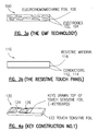
- FIGS 3a, 3b The Touch Sensitive Slide Technology
- Figures 3a and 3b are cross sections of two possible touch sensitive construction, resistive and EMF for the touch sensitive slide 14 in Figures 1a, 1b and 2.
- FIG. 3a shows EMF technology generally indicated as 100, which is known in the art and consists of opposing electrodes 102, 104 and an electro mechanical foil 106 sandwiched inbetween.
- Figure 3b shows a resistive touch panel technology generally indicated as 110, which is known in the art and consists of opposing conductors 112, 114 and a resistive material 116 sandwiched inbetween.
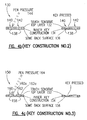
- FIGS. 4a, 4b, 4c The Inner Construction For the Touch Sensitive Slide Technology
- Figures 4a, 4b, 4c are cross sections of three different possibilities for a keyboard construction of the touch sensitive slide 14 in Figures 1a, 1b and 2.
- Figure 4a shows a keyboard construction generally indicated as 120 having a touch sensitive foil 122 with keys 124, 126 drawn on top thereof.
- the keys could be drawn on the touch sensitive foil.
- this embodiment provides a very good solution since the surface is flat.
- the keys 124, 126 are just visual symbols (not raised or lowered), it may not be easy for a user to locate the keys, so the key-pad operation may be more difficult for some when compared to the embodiments in Figures 4b, 4c discussed below.
- the comfortability may not be as good during typing when compared to the embodiments in Figures 4b, 4c discussed below.
- Figure 4b shows a keyboard construction generally indicated as 130 having a touch sensitive top layer 132, an inner key construction 134 and a back surface 136.
- the keyboard construction 130 has holes 138 underneath keys 140, 142 on the touch sensitive top layer 132.
- the keys 140, 142 could be clicked so there is a feel of movement.
- the keyboard construction 130 can be used with a pressure pen 144. This solution is also good for using the surface for drawing. Note that in this solution the surface of keys 140, 142 could be lower than the surface of the keyboard a little so the placement of keys 140, 142 could be felt from hollows, although this modification is not the best for using the surface for drawing.
- Figure 4c shows a keyboard construction generally indicated as 150 having a touch sensitive top layer 152, an inner key construction 154 and a back surface 156.
- the touch sensitive top layer 152 has keys 160, 162.
- the keys 160, 162 are design to provide a good feeling to their placement and to the movement when pressed.
- the keys 160, 162 could be constructed on top of the keyboard plastic surface or on the top of a printed circuit board (PCB). If made on top of a PCB, the conventional key indication (shortcutting) is possible with the embodiments in Figures 4b and 4c. If the placement is on top of the keyboard plastic surface, the user pressure could be sensed (at least with resistive foil) to indicate the difference with drawing or key pressing.
- PCB printed circuit board
- the combined keyboard and drawing table consists of a touch sensitive top layer.
- the top layer consists of a resistive or capacitive touch sensing system, (like EMF, Electro mechanic foil, or Force sensing resistor, from international electronic engineering, or some solution which is used in an existing touch screen).
- EMF Electro mechanic foil
- Force sensing resistor from international electronic engineering, or some solution which is used in an existing touch screen.
- no internal construction is needed.
- the keyboard keys are drawn on these materials, while in the keyboard mode the communications device 10 uses the key matrix; and in the drawing mode the drawing table is used, and the touch sensitive material is monitored using analog technology with high resolution.
- the top of the keyboard is flat.
- the flat solution is best for drawing, but the typing is not so comfortable.
- the keys could be constructed with an under layer construction by creating hills or hollows on the top surface, but in this solution the drawing is not so easy. If the shape of the keys are smooth, the drawing is possible, and certainly easier than trying to create the figures by typing.
- the keys could be drawn on the back surface. If the top layer is non-transparent, the mark of the keys should be drawn on the top of the top layer.
- the permanent key marks could be used because the standard keyboard is used in the typing mode; and in the drawing mode no marks are needed (corner signs could also be used).
- Minimizing the thickness of the device is one important goal of the present invention. With the solutions described herein, the thickness of the display is not increased, and by replacing the standard rubber keymat with this solution, the height of the keyboard could be decreased.
- the movable housing element may be a flip-type hinged structure that is hingeably mounted on the main body and also be used for other features such as a weight and hand sensing system.
- Figures 5a, 5b, 5c show an electronic device generally indicated as 200 such as a laptop computer or notebook.
- the device 200 has a main body 202 and a cover 204 that is hingeably connected to the main body 202.
- the main body 202 has one or more pressure sensitive keys generally indicated as 206.
- the scope of the invention is intended to cover embodiments in which the cover 204 has one or more pressure sensitive keys.
- the weight 208 can be placed on the one or more pressure sensitive keys 206 for providing a measurement.
- the weight 208 or 210 can be placed on the cover 204, which in the closed position contacts the one or more pressure sensitive keys 206 for providing a weight measurement.
- the measurement of the weight 210 would need scaling.
- a hand holding the device 200 applies a contact force on the main body 202 and the cover 204, which in the closed position contacts the one or more pressure sensitive keys 206 for providing a weight measurement.
- the main body 202 has a circuit for responding to the force applied to the one or more pressure sensitive keys 206 for providing the weight measurement.
- the device 200 has pressure sensitive keys 206, similar to that discussed above, (e.g. navigation keys with linear scrolling speed adjusting, with some pressure sensitive keys), these pressure sensitive keys could be used as a scale.
- the keys could also sense (especially with cover) if the device is kept in hand ( Figure 5c) or if it is on some open area i.e. on the table.
- the functionality of the HF (hands free) audio or ringing tones can be handled in a way similar to that discussed above in relation to the infrared sensor 28 in Figure 2.
- the audio level of the device 200 i.e. cellular phone
- HF the audio level of the device 200 with HF is optimized depending on the using mode.
- the main system is made from the touch sensitive key (i.e. resistive key).
- the touch sensitive key i.e. resistive key
- an AD-converter is needed to convert the information from the pressure to digital format onto the processor.
- the HF situation is usually solved with separate speakers for low volume and high volume sound in different places on the phone. Combining these two speakers into one has created the problem. But even in the separate speaker situations, the conductive noise from the covers are unpleasant.
- the information about the hand is important. If the device is pressed when kept in the hand, there is a possibility of the device being very near the ear. In that case, some other method could be used to minimize the effect of an unexpected loud sound. Of course, the device could be located somewhere else under pressure, so it must be able to make a loud enough sound also in this case but the warning operations from incoming loud sound must be better than in the situations where the device is not kept in the hand (both operations need some warning effects).
- resistive touch sensitive slide might be better because smaller current drain (when weight is on it for a short time only) and the capacitance could change the level of a zero-force under pressure for a long time.
- the invention comprises the features of construction, combination of elements, and arrangement of parts which will be exemplified in the construction hereinbefore set forth.
Abstract
Description
- The present invention relates in general to the field of telecommunications/mobile phones, and more precisely to a communications device including a touch sensitive slide having a keyboard and additional functionality.
- Many devices known in the art have a keyboard for writing text, but creating a picture with a keyboard is not easy. With a desktop computer, one approach has been to use a mouse. With smaller electronic devices, the approach has been to use touch screen technology. If the thickness of the screen has to be minimized, the usual approach has been to use a touch screen or an external mouse/trackball or a smaller touch sensitive drawing area. However, there are disadvantages to these approaches, because a touch screen can actually make the device thicker; an external mouse/trackball is an accessory which has to be carried with the device; and with the smaller touch sensitive areas, the resolution of the drawing capability is poor and the integration level of the approach is poor.
- Moreover, in communicator type electronic devices, it has been a problem to make a device which is small enough for when it is not used, and large enough for when it is used. WO 99/43134 relates to a communication device provided with a separate keyboard and touch screen on a moveable cover. There are devices in the art with slides which cover the keyboard, but in that solution the size of the display is reduced. In addition, the usual approach has been to make a thick and expensive keyboard able to slide (or keep the slide as a pure slide). For example, the prior art device includes a display, a touch screen and a slide body having a keypad and keypad cover. The thickness of the mechanical keyframe, keyboard rubber and printed circuit board (PCB) for contact pads is easily about 2-3 millimeters in thickness. In effect, the overall mechanical structure of the keyboard makes it thick. There is a need for a small electronic device having mouse-type capability in the industry. Also, there is a need for sensing the phone location while in use to minimize the effects of loud ringing in the known devices.
- In summary, the prior art communications device increases the thickness and cost of the overall communications device and does not have the extra features discussed in more detail below in the communications device of the present invention.
- The present invention provides a new and unique communications device as claimed in the appended claims.
- The communications device may be a mobile phone for communicating with a cellular communications system, as well as a Personal Digital Assistant (PDA), a notebook computer or other communication devices. The housing may also contain a speaker and a display.
- The touch sensitive slide is slidably mounted on the housing, and the preprinted key signs can include either a send key, an end key, a pound key, an asterisk key or number keys from zero to nine, which the user presses to provide user input signals that are a part of the touch sensitive slide signal. The touch sensitive slide can be made of touch sensitive resistive or capacitive material, and can have one or two parameter sensing in the X or Y direction. The touch sensitive slide may be also adaptable for using as a mouse or a drawing table for use together with the display of the communications device. This would enable the communications device to be used for windows-based word and data processing and graphical applications, as well as internet applications.
- In such a case, the touch sensitive slide can be slid to an open position to expose the display in full. The touch sensitive slide signal could also contain information about a mouse or drawing table inputs. In one embodiment, the touch sensitive slide is a flip-type hinged structure that is hingeably mounted on the housing. The use of an EMF-based foil structure can provide keyboard and drawing operations on both sides of the touch sensitive slide.
- In effect, the present invention can provide a combined keyboard and drawing table that consists of a touch sensitive top layer. Here, the top layer includes a resistive or capacitive touch sensing system. The keyboard keys could be drawn on the keyboard surface and in keyboard mode the device uses the key matrix, while in the drawing mode the drawing table is used and touch sensitive material is monitored in an analogue manner with high resolution.
- In the communications device of the present invention, drawing capability can be integrated into the keyboard which in this solution is even thinner than the standard rubber keymat solution.
- One advantage of the communications device is that it can provide a large drawing area with high resolution which is always with the device, and it will not increase the height of the keyboard or device. (It could make it even thinner).
- One advantage of the communications device of the present invention can be that, by using the touch sensitive slide, there is no need for a separate keyboard and touch screen equipment. For example, there is no need for a separate touch screen because the touch sensitive slide can be used as a mouse or drawing table. Also, the cost of the keyboard can be reduced since there is no need for a separate keyboard. In effect, the cost of the touch screen is translated into the cost of the touch sensitive slide.
- Moreover, by using the touch sensitive slide, the overall device can be made thinner. The thickness of the touch material layer is about 1/100 to 1/10 of a millimeter. The use of the touch sensitive slide eliminates the need for the use of a separate keyboard having a thick mechanical structure. The touch sensitive system could be made with a tenth of a millimeter which is significantly less than the standard keyboard.
- Also, some measurements of small weights are needed frequently (especially in applications where it is necessary to compare which of the two devices is heaviest).
- Figure 1a is a diagram of an electronic device in a closed position that is the subject matter of the present patent application.
- Figure 1b is a diagram of the electronic device shown in Figure 1a in an open position.
- Figure 2 is a block circuit diagram of the electronic device shown in Figures 1a, 1b.
- Figure 3a is a cross section of one touch sensitive construction using EMF technology for the electronic device shown in Figures 1a, 1b.
- Figure 3b is a cross section of another touch sensitive construction using a resistive touch panel technology for the electronic device shown in Figures 1a, 1b.
- Figure 4a is a cross section of one embodiment of a keyboard construction for the electronic device shown in Figures 1a, 1b.
- Figure 4b is a cross section of another embodiment of a keyboard construction for the electronic device shown in Figures 1a, 1b.
- Figure 4c is a cross section of still another embodiment of a keyboard construction for the electronic device shown in Figures 1a, 1b.
- Figure 5a shows an embodiment of an electronic device that is the subject matter of the present invention with the cover open.
- Figure 5b shows the embodiment of an electronic device shown in Figure 5a with the cover closed.
- Figure 5c shows the embodiment of an electronic device shown in Figure 5a with the cover closed and a hand griping the same.
- Figures 1a, 1b show an electronic device, including a communications device such as a mobile phone generally indicated as 10. The
mobile phone 10 communicates with a cellular communications system (not shown), although the scope of the invention is not intended to be limited to any particular application for the communications device. - Embodiments are envisioned in which the
electronics device 10 is a Personal Digital Assistant (PDA) (not shown), a notebook computer (not shown) or other electronic devices (not shown). - In Figures 1a, 1b, the
mobile phone 10 includes a movable housing element such as a touchsensitive slide 14 that has asurface 14a having preprintedkey signs 36, including a send key, an end key, a pound key, an asterisk key or number keys from zero to nine, which are pressed by the user to provide touch sensitive slide signals in the form of user inputs with communications information discussed below. As shown, the preprintedkey signs 36 are drawn or printed on thesurface 14a of the touchsensitive slide 14, but the scope of the invention is not intended to be limited to the manner of applying the preprintedkey signs 36 on the surface of the touchsensitive slide 14, as discussed below. - In Figure 1a, the touch
sensitive slide 14 is in a closed position for use mainly with preprintedkey signs 36. In Figure 1a, only part of thedisplay 26 can be seen when the touchsensitive slide 14 is in the closed position. The touchsensitive slide 14 will cover most of thedisplay 26 for reducing damage to thedisplay 26, which is a more expensive part to change or replace than the touchsensitive slide 14. The part of thedisplay 26 exposed will show, for example, a phone number dialed by the user, as well as other communications information. - In Figure 1b, the touch
sensitive slide 14 is in an open position for use with preprintedkey signs 36, as well as for use as a mouse pad and a drawing table as discussed below. As shown, when the touchsensitive slide 14 is in the open position, thesurface 14a, also known as a slide area, of the touchsensitive slide 14 can be used as a mouse pad or as a drawing table, and can be used together with afull display 26 as a screen. In this case, the touch sensitive slide signal would also include information about mouse pad or drawing table inputs. As shown, thecommunications device 10 includes adrawing tool 15 for such an application. In the drawing operation mode, the preprintedkey signs 36 are ignored so the touchsensitive slide 14 can be used for the mouse or drawing operation. - A slide position switch 25 discussed in relation to Figure 2 will sense the position of the touch
sensitive slide 14 in relation to themain body 12a. The slide position sensing discussed below may be used to coordinate and determine the partial or full display of information on thedisplay 26 depending on the position of the touchsensitive slide 14 in relation to the main body orhousing 12a. Different kinds of slide position sensing methods are known in the art and may be used, including but not limited to: mechanical, electric, magnet/reed-raly, magnet/hall sensor, etc. The scope of the invention is not intended to be limited to any particular kind of slide position sensing. - Figure 2 shows a block diagram of circuits in the
main body 12a and the touchsensitive slide 14. Similar elements in Figures 1a, 1b and 2 are labelled with similar reference numerals. - Figure 2 shows a block diagram of a main
body communications circuit 12 for themobile phone 10 shown in Figures 1a, 1b for use in combination with the touchsensitive slide 14. The main body orhousing 12a best shown in Figures 1a, 1b contains the mainbody communications circuit 12. - The main
body communications circuit 12 includes acontroller 16, amemory 18, akeyboard touchslide interface 20, akeyboard circuit 21, anRF circuit 23, anaudio circuit 24, aslide position switch 25, adisplay 26, aninfrared sensor 28, anantenna 29 and amicrophone 31, which are known circuits or elements in the art. - In operation, the main
body communications circuit 12 responds to a touch sensitive slide signal from the touchsensitive slide 14, for providing a communications signal to a communications system (not shown). The mainbody communications circuit 12 provides the communications signal to the communications system (not shown) via theantenna 29. - In Figure 2, the
speaker 22, themicrophone 31, and thedisplay 26 are all shown as a part of the mainbody communications circuit 12. However, the main body orhousing 12a may also be considered, for example, as containing thespeaker 22, themicrophone 31 and thedisplay 26. The scope of the invention is intended to include either having thespeaker 22, thedisplay 26 and themicrophone 31 as a part of the mainbody communications circuit 12 as generally indicated, or having these elements as a separate part of themain body 12a, or some combination thereof. Embodiments are also envisioned in which the speakers or microphone could be placed in the slide as well. If thespeaker 22, thedisplay 26 and themicrophone 31 are a part of themain body 12a, then the mainbody communications circuit 12 may also respond a microphone signal from the user via theaudio circuit 24 and themicrophone 31, and the provision of the communication signal may include providing a voice component signal to the user via theaudio circuit 24 and thespeaker 22, as well as providing a display component signal to the user via thedisplay 26. The scope of the invention is not intended to be limited to which of any one or more of these elements are a part of themain body 12a or the mainbody communications circuit 12. - As shown, the
keyboard circuit 21 is included in the mainbody communications circuit 12. However, embodiments are envisioned in which the necessary keys are implemented on thetouch slide 14 and operable when thetouch slide 14 is in a closed position as discussed above in relation to Figure 1a. - In Figure 2, the
controller 16 coordinates all communications functions for thecommunications device 10, including the exchange of communications information between the user and the communications system (not shown), the exchange of data and control signals between thememory 18, thekeyboard touchslide interface 20, thekeyboard circuit 21, theRF circuit 23, theaudio circuit 24, theslide position switch 25, thedisplay 26, theinfrared sensor 28, theantenna 29 and themicrophone 31, and also the exchange of communications information between the mainbody communications circuit 12 and the touchsensitive slide 14. Thecontroller 16 is implemented with software using a microprocessor architecture, which is known in the art, and typically includes thememory 18, one or more input/output devices and control, data, and address buses. Thecontroller 16 contains communications circuitry that is known in the art, and the scope of the invention is not intended to be limited to any particular type of communications circuitry, or whether the controller functions are performed using hardware, software or a combination thereof. By way of example only, the reader is referred to United Kingdom Patent Application No. GB 2 297 662, hereby incorporated by reference in its entirety, for such communications circuitry. - The
controller 16 receives the touch sensitive slide signal from the touchsensitive slide 14 via thekeyboard touchslide interface 20, and receives one or more input signals from theslide position switch 25 and theinfrared sensor 28, for implementing appropriate communications functions by processing user inputs from the touchsensitive slide 14, as described in further detail below. - A person skilled in the art would appreciate how the
controller 16 cooperates with the other elements shown in Figure 2. By way of example only, the functions of these other elements are briefly described below. Thecontroller 16 provides audio output signals to theaudio circuit 24, for providing voice signals to thespeaker 22. Thecontroller 16 receives audio input signals from themicrophone 31 via theaudio circuit 24 for receiving voice signals from the user. Thecontroller 16 provides display information signals to thedisplay 26 for displaying communications information to the user. Theinfrared sensing device 28 senses the placement or location of thecommunications device 10, as well as the main body orhousing 12a as best shown in Figures 1a, 1b, and provides an infrared sensor signal to thecontroller 16, all discussed in more detail below. Thecontroller 16 provides a ring control signal to theaudio circuit 24 for adjusting the volume of thespeaker 22 in relation to an input from theinfrared sensor 28 discussed below. Theslide position switch 25 responds to the position of the touchsensitive slide 14 in relation to themain body 12a, for providing a slide position switch signal to thecontroller 16 containing information about the position of the touchsensitive slide 14 in relation to the main body orhousing 12a. - The touch
sensitive slide 14 includes a touchsensitive slide circuitry 30 and aslide interface circuit 32. In operation, the touchsensitive slide 14 responds to a contact force by a user (not shown), for providing the touch sensitive slide signal containing information about a position of the contact force applied by the user on the touchsensitive slide 14. The information includes communications information about user keyboard inputs and mouse and drawing table inputs that are discussed above in relation to Figures 1a, 1b. - The touch
sensitive slide 14 is known in the art, and may include touch sensitive resistive or capacitive material, and may have one or two parameter sensing in the X or Y direction. Electro-Mechanical Film (also known as "EMF-material") may be used which is very robust and withstands very hard handling (capacitive-type sensing system), and which is shown and described in United States Patent No. 4,654,546, hereby incorporated by reference in its entirety. The scope of the invention is not intended to be limited to such Electro-Mechanical Film, because embodiments are envisioned and described below using other types of thin touch sensitive resistive or capacitive material known in the art, including but not limited to a resistive touch panel. By way of example, Figures 3a, 3b, discussed below, show two different technologies that can be used for the touchsensitive slide 14. - In Figure 2, the touch
sensitive slide circuitry 30, responds to the position of the contact force applied by the user, for providing the touch sensitive slide signal containing information about the position of the contact force applied by the user to the touchsensitive slide interface 32. The touchsensitive slide interface 32 cooperates with thekeyboard touchslide interface 20, as discussed above, for providing the touch sensitive signal to thecontroller 16. - The touch
sensitive slide 14 is slidably mounted on the main body orhousing 12a as shown and discussed in relation to Figures 1a, 1b. In this embodiment, the touchsensitive slide interface 32 would include a slidably mounted interface for providing the touchsensitive slide 14 to thekeyboard touchslide interface 20 of the mainbody communications circuit 12. In effect, the standard keyboard on the touchsensitive slide 14 would have drivers and other lines on the interface between the touchsensitive slide 14 and the main body orhousing 12a. The drivers provide the touch sensitive slide signal to thekeyboard touchslide interface 20 of the mainbody communications circuit 12. Such a touchsensitive slide interface 32 is known in the art, and can be based on one or two parameter sensing (x and y directions). In particular, one kind of interface known in the art would need only three wires. The mouse-type operation and the drawing table operation are easily adapted therein because the cursor movement is based mainly on the change of the resistance or capacitance, and in such a way the different positions of the slide could be compensated. The scope of the invention is not intended to be limited to any particular slide interface circuit or system. - As shown, the touch
sensitive slide circuitry 30 may include a touch sensitive slide color changing circuit 34 (Figure 2) that will change the color of the surface of the touchsensitive slide 14, depending on the contact force applied by the user. A touchsensitive slide circuitry 30 having such a touch sensitive slidecolor changing circuit 34 is known in the art, and the scope of the invention is intended to be limited to any particular type thereof. - The touch
sensitive slide circuitry 30 may also have means for changing the color of the surface thereof depending on the contact force applied by the user. In operation, materials are used to cover the touch sensitive slide 14 (or under it) which changes the color because of the pressure. With this kind of approach the overall usability of the touchsensitive slide 14 could be increased. - With the touch sensitive system of the present invention, each preprinted sign key 36 that is pressed could be sensed, and the keying could be confirmed by a 'click' sound. In operation, the
controller 16 would provide a key stroke confirmation signal to theaudio circuit 24 to confirm a key stroke from a user, which in turn provides a confirmation signal to thespeaker 22 to generate a "click" sound when a respective preprinted key sign 36 (Figures 1a, 1b) is pressed on the touchsensitive slide 14. - In Figures 1a, 1b, and 2, the
infrared sensor device 28 will detect the placement or location of thecommunications device 10 in relation to another object, such as a head of a user, as well as an object resting on the touchsensitive slide 14. Infrared sensing may be used to determine if thecommunications device 10 is near the user's head or not. When thecommunications device 10 is near the user's head, it is preferable to have a normal ring level. In comparison, when thecommunications device 10 is not near the user's head, it is preferable to have a higher than normal ring level. (If thecommunications device 10 is in the bag, the sound (ringing tones) should be as loud as possible.) Separation of these two situations just based on one point of sensing is critical. By using the touchsensitive slide 14, the difference between the user's head and bag could be determined and separated. When thecommunications device 10 is in the bag, it is very probable that there is something covering theinfrared sensor 28 near the headset speaker, and at the same time there is something touching or gently pressing the touch-sensitive slide 14. When thecommunications device 10 is used near the user's head, theinfrared sensor 28 could sense the user's head, but because of the shape of the user's head, nothing is pressing the touchsensitive slide 14, if the slide is open or closed. The present invention also makes the user's head sensing more reliable. This information not only can be used to adjust ringing tones, but may be used for other possible solutions in relation to determining the location of the phone. - Such infrared sensor devices are known in the art, and the scope of the invention is not intended to be limited to any particular kind thereof. By way of example, one such infrared sensor device is shown and described in United States Patent No. 5,729,604, hereby incorporated by reference.
- In operation, the
infrared sensor device 28 has an infrared sensor and an infrared sensor circuit for detecting the placement or location of thecommunications device 10 in relation to the object. Theinfrared sensor circuit 28 would respond to an infrared sensor signal, for providing an infrared sensor circuit signal to thecontroller 16 containing information about the placement or location of thecommunications device 10 in relation to the object. Thecontroller 16 would respond to the infrared sensor circuit signal and further responds to information contained in the touch sensitive slide signal, for adjusting the ringing of the audio circuit. As discussed above, the infrared sensor signal contains information about the location of the sensor in relation to a user's ear, while the touch sensitive slide signal contains information about any contact on the touch sensitive slide that might indicate whether the communications device is resting against the object. - In Figures 1a, 1b and 2, the
speaker 22 provides a keying guide sound having information about the preprintedkey signs 36 which is activated by applying less pressure on the touchsensitive slide 14 for assisting people having a sight handicap. For blind people, the guide sound could inform the user of the key they are going to push. - Figures 3a and 3b are cross sections of two possible touch sensitive construction, resistive and EMF for the touch
sensitive slide 14 in Figures 1a, 1b and 2. - Figure 3a shows EMF technology generally indicated as 100, which is known in the art and consists of opposing electrodes 102, 104 and an electro
mechanical foil 106 sandwiched inbetween. - Figure 3b shows a resistive touch panel technology generally indicated as 110, which is known in the art and consists of opposing conductors 112, 114 and a
resistive material 116 sandwiched inbetween. - A person skilled in the art would appreciate how to implement these embodiments in Figures 3a, 3b, which may include the use of a two-channel AD converter (not shown) and voltage source (not shown).
- Figures 4a, 4b, 4c are cross sections of three different possibilities for a keyboard construction of the touch
sensitive slide 14 in Figures 1a, 1b and 2. - Figure 4a shows a keyboard construction generally indicated as 120 having a touch
sensitive foil 122 withkeys keys - Figure 4b shows a keyboard construction generally indicated as 130 having a touch sensitive
top layer 132, an inner key construction 134 and a back surface 136. In Figure 4b, there is a simple inner key construction. Thekeyboard construction 130 hasholes 138 underneathkeys top layer 132. During writing, thekeys keyboard construction 130 can be used with apressure pen 144. This solution is also good for using the surface for drawing. Note that in this solution the surface ofkeys keys - Figure 4c shows a keyboard construction generally indicated as 150 having a touch sensitive top layer 152, an inner key construction 154 and a back surface 156. This provides a very well-round solution for the following reasons: The touch sensitive top layer 152 has keys 160, 162. There are
hills - Note that the keys 160, 162 could be constructed on top of the keyboard plastic surface or on the top of a printed circuit board (PCB). If made on top of a PCB, the conventional key indication (shortcutting) is possible with the embodiments in Figures 4b and 4c. If the placement is on top of the keyboard plastic surface, the user pressure could be sensed (at least with resistive foil) to indicate the difference with drawing or key pressing.
- In Figures 4a, 4b, 4c, the combined keyboard and drawing table consists of a touch sensitive top layer. The top layer consists of a resistive or capacitive touch sensing system, (like EMF, Electro mechanic foil, or Force sensing resistor, from international electronic engineering, or some solution which is used in an existing touch screen). In the simplest solution shown in Figure 4a, no internal construction is needed. The keyboard keys are drawn on these materials, while in the keyboard mode the
communications device 10 uses the key matrix; and in the drawing mode the drawing table is used, and the touch sensitive material is monitored using analog technology with high resolution. - The other solutions in Figures 4b, 4c add some construction under the touch sensitive top layer where the keyboard matrix could be configured and a small movement to the keys could be made. With this solution the feeling of a push could be arranged more easily than with the first solution in Figure 4a. The movement of the keys cannot be too large, because most of the touch sensitive foils cannot withstand very large movements (but, for example, EMF should withstand the movement better than others).
- In all these solutions in Figures 4a, 4b, 4c, the top of the keyboard is flat. The flat solution is best for drawing, but the typing is not so comfortable. On the other hand, the keys could be constructed with an under layer construction by creating hills or hollows on the top surface, but in this solution the drawing is not so easy. If the shape of the keys are smooth, the drawing is possible, and certainly easier than trying to create the figures by typing.
- Note that these solutions also enable icon-based displays, because with this solution the user could use their finger like a mouse. Also, the drawing is easy because the keyboard size is almost the same as the size of the display, and in that way locating of a drawing point is easy. Also, the usability (i.e. the mouse operation or drawing operation) is just a design issue. For example, in the drawing mode locating of a placement could be done with a finger and the cursor on the screen. When the starting point has been determined, one key is pressed down and then the user could draw a visible line to the screen.
- If the top layer and internal construction are transparent, the keys could be drawn on the back surface. If the top layer is non-transparent, the mark of the keys should be drawn on the top of the top layer. The permanent key marks could be used because the standard keyboard is used in the typing mode; and in the drawing mode no marks are needed (corner signs could also be used).
- Minimizing the thickness of the device is one important goal of the present invention. With the solutions described herein, the thickness of the display is not increased, and by replacing the standard rubber keymat with this solution, the height of the keyboard could be decreased.
- With this option the possibility of drawing could be included to a device like Nokia 9000 Communicator, and the height of the device will be decreased.
- In the present invention, the movable housing element may be a flip-type hinged structure that is hingeably mounted on the main body and also be used for other features such as a weight and hand sensing system.
- For example, Figures 5a, 5b, 5c show an electronic device generally indicated as 200 such as a laptop computer or notebook. As shown in Figures 5a, 5b, 5c the
device 200 has amain body 202 and acover 204 that is hingeably connected to themain body 202. As shown, themain body 202 has one or more pressure sensitive keys generally indicated as 206. Although not shown, the scope of the invention is intended to cover embodiments in which thecover 204 has one or more pressure sensitive keys. - In operation, in Figure 5a the
weight 208 can be placed on the one or more pressuresensitive keys 206 for providing a measurement. In Figure 5b, theweight cover 204, which in the closed position contacts the one or more pressuresensitive keys 206 for providing a weight measurement. The measurement of theweight 210 would need scaling. In Figure 5c, a hand holding thedevice 200 applies a contact force on themain body 202 and thecover 204, which in the closed position contacts the one or more pressuresensitive keys 206 for providing a weight measurement. - The
main body 202 has a circuit for responding to the force applied to the one or more pressuresensitive keys 206 for providing the weight measurement. - In summary, if the
device 200 has pressuresensitive keys 206, similar to that discussed above, (e.g. navigation keys with linear scrolling speed adjusting, with some pressure sensitive keys), these pressure sensitive keys could be used as a scale. The keys could also sense (especially with cover) if the device is kept in hand (Figure 5c) or if it is on some open area i.e. on the table. Depending on the information about hand pressure, the functionality of the HF (hands free) audio or ringing tones can be handled in a way similar to that discussed above in relation to theinfrared sensor 28 in Figure 2. - As discussed above, the audio level of the device 200 (i.e. cellular phone) with HF is optimized depending on the using mode.
- In addition, some measurements of small weights are needed frequently (especially when comparing which one is heaviest). With this functionality the weight measuring option is easily on your hand if you are carrying the device (i.e. cellular phone).
- The main system is made from the touch sensitive key (i.e. resistive key). Depending on the application, there could be some systems (i.e. cover) to conduct the force from some point/area to the key. Also an AD-converter is needed to convert the information from the pressure to digital format onto the processor.
- For hand recognition, a rough estimation of the pressure is needed. For weight measuring, a calibration is needed. In the case of conducting the force from some point to another, some kind of information is needed about the effect of the conduction path of the force and good measurement information to users to make proper measurements.
- The HF situation is usually solved with separate speakers for low volume and high volume sound in different places on the phone. Combining these two speakers into one has created the problem. But even in the separate speaker situations, the conductive noise from the covers are unpleasant.
- In the case of using one speaker, the information about the hand is important. If the device is pressed when kept in the hand, there is a possibility of the device being very near the ear. In that case, some other method could be used to minimize the effect of an unexpected loud sound. Of course, the device could be located somewhere else under pressure, so it must be able to make a loud enough sound also in this case but the warning operations from incoming loud sound must be better than in the situations where the device is not kept in the hand (both operations need some warning effects).
- The use of a resistive touch sensitive slide might be better because smaller current drain (when weight is on it for a short time only) and the capacitance could change the level of a zero-force under pressure for a long time.
- Accordingly, the invention comprises the features of construction, combination of elements, and arrangement of parts which will be exemplified in the construction hereinbefore set forth.
- It will thus be seen that the objects set forth above, and those made apparent from the preceding description, are efficiently attained and, since certain changes may be made in the above construction without departing from the scope of the invention, it is intended that all matter contained in the above description or shown in the accompanying drawings shall be interpreted as illustrative and not in a limiting sense.
Claims (24)
- A communications device (10), comprising:a housing (12a) containing a communications circuit (12);a touch sensitive slide (14) mounted on the housing (12a);the touch sensitive slide (14) being responsive to a contact force by a user, and having touch sensitive circuitry (30) for providing a contact force position signal indicative of a position of the contact force applied by the user on the touch sensitive slide (14); andmeans (25) for providing a touch sensitive slide position signal indicative of a position of the touch sensitive slide in relation to the housing,wherein the touch sensitive slide position signal and the contact force position signal together comprising a touch sensitive slide signal, and wherein the main body communications circuit (12) is responsive to the touch sensitive slide signal for providing a communications signal to a communications system;
characterised in that:the touch sensitive slide (14) functions as a keyboard, the contact force position signal containing information about keyboard inputs by the user, when the touch sensitive slide (14) is in a closed position in relation to the housing. - A communications device (10) according to claim 1, wherein the touch sensitive slide (14) changes to a different function when the touch sensitive slide (14) is in an open position in relation to the housing.
- A communications device (10) according to claim 1 or claim 2,
wherein the touch sensitive slide (14) is a flip-type hinged structure. - A communications device (10) according to claim 1 or claim 2,
wherein the touch sensitive slide (14) is slidably mounted on the housing (12a). - A communications device (10) according to claim any preceding claim,
wherein the touch sensitive slide (14) functions as a mouse pad or a drawing table when the touch sensitive slide (14) is in an open position in relation to the housing (12a); and
wherein the touch sensitive slide signal contains information about mouse or drawing table inputs by the user. - A communications device (10) according to any preceding claim,
wherein the communications circuit (12) includes a controller (16), and a keyboard touchslide interface (20); and
wherein the keyboard touchslide interface (20) provides the touch sensitive slide signals to the controller (16). - A communications device (10) according to claim 6,
wherein the communications circuit (12) includes an RF circuit (23);
wherein the controller (16) processes the touch sensitive slide signal and provides the communications signal to the RF circuit (23); and
wherein the RF circuit (23) provides the communications signal to the communications system. - A communications device (10) according to claim 6 or claim 7,
wherein the touch sensitive slide (14) includes a slide interface circuit (32);
wherein the touch sensitive circuitry (30) provides the touch sensitive slide signal to the slide interface (32); and
wherein the slide interface (32) cooperates with a or the keyboard touchslide interface (20) for providing the touch sensitive slide signal to the controller (16). - A communications device (10) according to any preceding claim,
wherein the touch sensitive slide (14) is made of touch sensitive resistive or capacitive material or electromechanical foil. - A communications device (10) according to any preceding claim,
wherein the touch sensitive slide has a keyboard with preprinted key signs (36), including either a send key, an end key, a pound key, an asterisk key or number keys from zero to nine; and
wherein the touch sensitive slide signal contains information about the preprinted key signs contacted by the user. - A communications device (10) according to any preceding claim,
wherein the communications device (10) has a display (26) for providing communications information to the user; and
wherein the touch sensitive slide (14) covers a part of the display when in the closed position in relation to the housing (12a). - A communications device (10) according to any preceding claim,
wherein the communications device (10) has a slide position switch (25) connected between the housing (12a) and the touch sensitive slide (14), that responds to the position of the touch sensitive slide (14) in relation to the housing (12a), for providing the touch sensitive slide position signal containing information about the position of the touch sensitive slide (14) in relation to the housing (12a). - A communications device (10) according to claim any preceding claim,
wherein the communications circuit (12) includes an infrared (IR) sensor circuit (28) for detecting the placement or location of the communications device (10) in relation to an object, for providing an infrared (IR) sensor circuit signal containing information about the placement or location of the communications device (10) in relation to the object. - A communications device (10) according to claim 13,
wherein the communications device (10) includes a speaker (22) for providing a ring for an incoming call, and for providing voice signals to the user;
wherein a or the controller (16) of the communications circuit (12) is responsive to the infrared (IR) sensor circuit signal, for providing a ring control signal; and
wherein the communications circuit (12) also includes an audio circuit (24), responsive to the ring control signal, for adjusting the volume of the ring of the speaker (22) in response to a ring control signal from the controller (16). - A communications device (10) according to any preceding claim,
wherein a keying guide sound is activated by applying less pressure than that needed to provide keyboard inputs, the keying guide sound being provided by a or the speaker (22) and containing audio information about the preprinted key signs (36). - A communications device (10) according to any preceding claim,
wherein the an or the controller (16) of the communications circuit 12 provides a keystroke confirmation signal to the audio circuit (24) to confirm a key stroke; and
wherein an or the audio circuit (24) of the communications circuit (12) responds to the keystroke confirmation signal, for providing an audio confirmation signal to a or the speaker (22) to provide a "click" sound when the preprinted key signs (36) are pressed on the touch sensitive slide (14). - A communications device (10) according to any preceding claim,
wherein the touch sensitive slideg(1 4) has one or two parameter sensing in the X or Y direction. - A communications device (10) according to any preceding claim,
wherein the touch sensitive slide (14) has slide circuitry (30) having means for changing the color of the surface (14a) thereof depending on the contact force applied by the user. - A communications device (10) according to any preceding claim,
wherein the preprinted key signs (36) are drawn on the surface (14a) of the keyboard. - A communications device (10) according to claim 19,
wherein the preprinted key signs (36) are drawn on and raised above the surface (14a) of the keyboard. - A communications device (10) according to claim 19,
wherein the preprinted key signs (36) are drawn on and hollowed below the surface (14a) of the keyboard. - A communications device (10) according to any preceding claim,
wherein the touch sensitive slide (14) has a keyboard construction that includes a back surface (136, 156), an inner key construction (134, 154) and a touch sensitive top layer (132, 152). - A communications device (10) according to claim 22,
wherein there is a space (138, 158) formed in the inner key construction (134, 154) between the back surface (136, 156) and the touch sensitive top layer (132, 152) for pressing down the preprinted key signs (36). - A communications device according to any preceding claim,
wherein the communications device (10) is a mobile phone.
Applications Claiming Priority (2)
| Application Number | Priority Date | Filing Date | Title |
|---|---|---|---|
| US09/451,167 US7006077B1 (en) | 1999-11-30 | 1999-11-30 | Electronic device having touch sensitive slide |
| US451167 | 1999-11-30 |
Publications (4)
| Publication Number | Publication Date |
|---|---|
| EP1107101A2 EP1107101A2 (en) | 2001-06-13 |
| EP1107101A3 EP1107101A3 (en) | 2002-10-09 |
| EP1107101A9 EP1107101A9 (en) | 2005-06-15 |
| EP1107101B1 true EP1107101B1 (en) | 2007-06-06 |
Family
ID=23791079
Family Applications (1)
| Application Number | Title | Priority Date | Filing Date |
|---|---|---|---|
| EP00310359A Expired - Lifetime EP1107101B1 (en) | 1999-11-30 | 2000-11-22 | Electronic device having touch sensitive slide |
Country Status (5)
| Country | Link |
|---|---|
| US (1) | US7006077B1 (en) |
| EP (1) | EP1107101B1 (en) |
| KR (1) | KR100809088B1 (en) |
| AT (1) | ATE364200T1 (en) |
| DE (1) | DE60035095T9 (en) |
Cited By (3)
| Publication number | Priority date | Publication date | Assignee | Title |
|---|---|---|---|---|
| US8150482B2 (en) | 2008-01-08 | 2012-04-03 | Hewlett-Packard Development Company, L.P. | Mobile computing device with moveable housing segments |
| US8200298B2 (en) | 2008-01-08 | 2012-06-12 | Hewlett-Packard Development Company, L.P. | Keypad housing configuration for a mobile computing device |
| US8233948B2 (en) | 2007-12-11 | 2012-07-31 | Hewlett-Packard Development Company, L.P. | Slider assembly for a housing of a mobile computing device |
Families Citing this family (87)
| Publication number | Priority date | Publication date | Assignee | Title |
|---|---|---|---|---|
| FI19992510A (en) * | 1999-11-24 | 2001-05-25 | Nokia Mobile Phones Ltd | Electronic device and method in the electronic device |
| EP2270633A1 (en) * | 2000-10-24 | 2011-01-05 | Nokia Corp. | Touchpad |
| US6873863B2 (en) * | 2001-03-19 | 2005-03-29 | Nokia Mobile Phones Ltd. | Touch sensitive navigation surfaces for mobile telecommunication systems |
| US7692667B2 (en) * | 2001-08-17 | 2010-04-06 | Palm, Inc. | Handheld computer having moveable segments that are interactive with an integrated display |
| US20030034987A1 (en) * | 2001-08-17 | 2003-02-20 | William Webb | Handheld computer having moveable segments that can be adjusted to affect a size of the handheld computer |
| DE10143273A1 (en) * | 2001-09-04 | 2003-03-27 | Siemens Ag | Pressure sensitive input for hand-held electronic unit, e.g. PDA, mobile- or wrist phone, has keys with analog pressure sensors connected to evaluation unit |
| US20070085841A1 (en) * | 2001-10-22 | 2007-04-19 | Apple Computer, Inc. | Method and apparatus for accelerated scrolling |
| US7345671B2 (en) | 2001-10-22 | 2008-03-18 | Apple Inc. | Method and apparatus for use of rotational user inputs |
| US7312785B2 (en) * | 2001-10-22 | 2007-12-25 | Apple Inc. | Method and apparatus for accelerated scrolling |
| US8095879B2 (en) * | 2002-12-10 | 2012-01-10 | Neonode Inc. | User interface for mobile handheld computer unit |
| US9052777B2 (en) | 2001-11-02 | 2015-06-09 | Neonode Inc. | Optical elements with alternating reflective lens facets |
| US9778794B2 (en) | 2001-11-02 | 2017-10-03 | Neonode Inc. | Light-based touch screen |
| US8674966B2 (en) | 2001-11-02 | 2014-03-18 | Neonode Inc. | ASIC controller for light-based touch screen |
| US20050140643A1 (en) * | 2002-01-17 | 2005-06-30 | Terje Skaug | Pointing device |
| US7333092B2 (en) | 2002-02-25 | 2008-02-19 | Apple Computer, Inc. | Touch pad for handheld device |
| DE60238721D1 (en) | 2002-06-27 | 2011-02-03 | Nokia Corp | COVER FOR AN ELECTRONIC DEVICE AND ELECTRONIC DEVICE WITH A COVER |
| US8416217B1 (en) | 2002-11-04 | 2013-04-09 | Neonode Inc. | Light-based finger gesture user interface |
| DE10311294A1 (en) * | 2003-03-12 | 2004-09-23 | Völckers, Oliver | Integrated system for the identification of keys in a keyboard uses keys with specific resistance values |
| KR100511305B1 (en) * | 2003-04-15 | 2005-08-31 | 엘지전자 주식회사 | A structure and a device and a method of selecting menu for slide type mobile phone |
| US20070117599A1 (en) * | 2003-07-30 | 2007-05-24 | Rajendra Kumar | Handheld computing and communication device with a multi-position keyboard-lid |
| US7499040B2 (en) * | 2003-08-18 | 2009-03-03 | Apple Inc. | Movable touch pad with added functionality |
| US20070152977A1 (en) * | 2005-12-30 | 2007-07-05 | Apple Computer, Inc. | Illuminated touchpad |
| US20060181517A1 (en) * | 2005-02-11 | 2006-08-17 | Apple Computer, Inc. | Display actuator |
| US7495659B2 (en) * | 2003-11-25 | 2009-02-24 | Apple Inc. | Touch pad for handheld device |
| US8059099B2 (en) * | 2006-06-02 | 2011-11-15 | Apple Inc. | Techniques for interactive input to portable electronic devices |
| US7620915B2 (en) | 2004-02-13 | 2009-11-17 | Ludwig Lester F | Electronic document editing employing multiple cursors |
| US20050219228A1 (en) * | 2004-03-31 | 2005-10-06 | Motorola, Inc. | Intuitive user interface and method |
| ATE553429T1 (en) * | 2004-08-16 | 2012-04-15 | Apple Inc | METHOD FOR INCREASING THE SPATIAL RESOLUTION OF TOUCH-SENSITIVE DEVICES |
| US7528824B2 (en) | 2004-09-30 | 2009-05-05 | Microsoft Corporation | Keyboard or other input device using ranging for detection of control piece movement |
| US7557795B2 (en) | 2005-06-30 | 2009-07-07 | Microsoft Corporation | Input device using laser self-mixing velocimeter |
| US7671837B2 (en) * | 2005-09-06 | 2010-03-02 | Apple Inc. | Scrolling input arrangements using capacitive sensors on a flexible membrane |
| US7880729B2 (en) * | 2005-10-11 | 2011-02-01 | Apple Inc. | Center button isolation ring |
| CN101300108B (en) * | 2005-11-04 | 2012-08-08 | 罗伯特·博世有限公司 | Drill with solid state speed control and method of operating |
| US7543750B2 (en) | 2005-11-08 | 2009-06-09 | Microsoft Corporation | Laser velocimetric image scanning |
| US7505033B2 (en) | 2005-11-14 | 2009-03-17 | Microsoft Corporation | Speckle-based two-dimensional motion tracking |
| US20070152983A1 (en) | 2005-12-30 | 2007-07-05 | Apple Computer, Inc. | Touch pad with symbols based on mode |
| US20070296697A1 (en) * | 2006-06-26 | 2007-12-27 | Areson Technology Corp. | Wireless cursor indicating device |
| US9360967B2 (en) * | 2006-07-06 | 2016-06-07 | Apple Inc. | Mutual capacitance touch sensing device |
| US8743060B2 (en) * | 2006-07-06 | 2014-06-03 | Apple Inc. | Mutual capacitance touch sensing device |
| US8022935B2 (en) | 2006-07-06 | 2011-09-20 | Apple Inc. | Capacitance sensing electrode with integrated I/O mechanism |
| US20080006454A1 (en) * | 2006-07-10 | 2008-01-10 | Apple Computer, Inc. | Mutual capacitance touch sensing device |
| US7795553B2 (en) | 2006-09-11 | 2010-09-14 | Apple Inc. | Hybrid button |
| US20080088600A1 (en) * | 2006-10-11 | 2008-04-17 | Apple Inc. | Method and apparatus for implementing multiple push buttons in a user input device |
| US8274479B2 (en) * | 2006-10-11 | 2012-09-25 | Apple Inc. | Gimballed scroll wheel |
| US20080088597A1 (en) * | 2006-10-11 | 2008-04-17 | Apple Inc. | Sensor configurations in a user input device |
| US8482530B2 (en) * | 2006-11-13 | 2013-07-09 | Apple Inc. | Method of capacitively sensing finger position |
| US11449158B2 (en) * | 2006-12-28 | 2022-09-20 | International Business Machines Corporation | Interactive, touch-sensitive user interface device |
| TW200828946A (en) * | 2006-12-29 | 2008-07-01 | Asustek Comp Inc | Wireless handheld communication device |
| EP1967937A1 (en) * | 2007-03-06 | 2008-09-10 | Polymer Vision Limited | A display unit, a method and a computer program product |
| CN101296588A (en) * | 2007-04-24 | 2008-10-29 | 鸿富锦精密工业(深圳)有限公司 | Electronic apparatus |
| US9654104B2 (en) * | 2007-07-17 | 2017-05-16 | Apple Inc. | Resistive force sensor with capacitive discrimination |
| US8126519B2 (en) * | 2007-08-31 | 2012-02-28 | Hewlett-Packard Development Company, L.P. | Housing for mobile computing device having construction to slide and pivot into multiple positions |
| KR101348721B1 (en) | 2007-09-03 | 2014-01-08 | 엘지전자 주식회사 | Mobile terminal and it's touch recognition method |
| WO2009032898A2 (en) * | 2007-09-04 | 2009-03-12 | Apple Inc. | Compact input device |
| US20090058801A1 (en) * | 2007-09-04 | 2009-03-05 | Apple Inc. | Fluid motion user interface control |
| US8683378B2 (en) | 2007-09-04 | 2014-03-25 | Apple Inc. | Scrolling techniques for user interfaces |
| US20090073130A1 (en) * | 2007-09-17 | 2009-03-19 | Apple Inc. | Device having cover with integrally formed sensor |
| US8416198B2 (en) | 2007-12-03 | 2013-04-09 | Apple Inc. | Multi-dimensional scroll wheel |
| US20090167507A1 (en) * | 2007-12-07 | 2009-07-02 | Nokia Corporation | User interface |
| US8125461B2 (en) * | 2008-01-11 | 2012-02-28 | Apple Inc. | Dynamic input graphic display |
| US8820133B2 (en) * | 2008-02-01 | 2014-09-02 | Apple Inc. | Co-extruded materials and methods |
| US9454256B2 (en) | 2008-03-14 | 2016-09-27 | Apple Inc. | Sensor configurations of an input device that are switchable based on mode |
| US8174503B2 (en) * | 2008-05-17 | 2012-05-08 | David H. Cain | Touch-based authentication of a mobile device through user generated pattern creation |
| US8553014B2 (en) | 2008-06-19 | 2013-10-08 | Neonode Inc. | Optical touch screen systems using total internal reflection |
| US20100058251A1 (en) * | 2008-08-27 | 2010-03-04 | Apple Inc. | Omnidirectional gesture detection |
| CN101673144A (en) * | 2008-09-12 | 2010-03-17 | 索尼爱立信移动通讯有限公司 | Keyboard and electronic equipment for eliminating language difference |
| US8816967B2 (en) | 2008-09-25 | 2014-08-26 | Apple Inc. | Capacitive sensor having electrodes arranged on the substrate and the flex circuit |
| CN101729633B (en) * | 2008-10-27 | 2014-03-26 | 深圳富泰宏精密工业有限公司 | Key device |
| US8576179B2 (en) * | 2008-11-26 | 2013-11-05 | Motorola Mobility Llc | Slider form factor devices and methods for morphing indicia visible through a transparent member |
| US8395590B2 (en) * | 2008-12-17 | 2013-03-12 | Apple Inc. | Integrated contact switch and touch sensor elements |
| US9158416B2 (en) | 2009-02-15 | 2015-10-13 | Neonode Inc. | Resilient light-based touch surface |
| US8775023B2 (en) | 2009-02-15 | 2014-07-08 | Neanode Inc. | Light-based touch controls on a steering wheel and dashboard |
| US9354751B2 (en) * | 2009-05-15 | 2016-05-31 | Apple Inc. | Input device with optimized capacitive sensing |
| US8872771B2 (en) * | 2009-07-07 | 2014-10-28 | Apple Inc. | Touch sensing device having conductive nodes |
| KR20110013606A (en) * | 2009-08-03 | 2011-02-10 | 엘지전자 주식회사 | Method for executing menu in mobile terminal and mobile terminal thereof |
| KR20110105574A (en) * | 2010-03-19 | 2011-09-27 | 삼성전자주식회사 | Apparatus and method for displaying in portable terminal |
| CN102202130A (en) * | 2010-03-25 | 2011-09-28 | 鸿富锦精密工业(深圳)有限公司 | Electronic device with unlocking and locking functions and unlocking and locking method thereof |
| CN102262464B (en) * | 2010-05-25 | 2014-10-29 | 深圳富泰宏精密工业有限公司 | Touch transparent keyboard |
| KR101399142B1 (en) * | 2012-03-11 | 2014-05-27 | 네오노드, 인크. | Optical touch screen using total internal reflection |
| US20160005150A1 (en) * | 2012-09-25 | 2016-01-07 | Benjamin Firooz Ghassabian | Systems to enhance data entry in mobile and fixed environment |
| US9092093B2 (en) | 2012-11-27 | 2015-07-28 | Neonode Inc. | Steering wheel user interface |
| US20150355725A1 (en) * | 2013-01-15 | 2015-12-10 | Nokia Technologies Oy | Input Device |
| KR20140139648A (en) * | 2013-05-27 | 2014-12-08 | 삼성전자주식회사 | Protecting cover |
| CN108572759B (en) | 2017-03-14 | 2023-10-24 | 恩智浦美国有限公司 | Touch sensor and method for determining touch position |
| US10909338B2 (en) * | 2017-03-15 | 2021-02-02 | Hong Kong R&D Centre for Logistics and Supply Chain Management Enabling Technologies Limited | Radio frequency communication guiding device |
| WO2020112585A1 (en) | 2018-11-28 | 2020-06-04 | Neonode Inc. | Motorist user interface sensor |
| CN116420125A (en) | 2020-09-30 | 2023-07-11 | 内奥诺德公司 | Optical touch sensor |
Family Cites Families (28)
| Publication number | Priority date | Publication date | Assignee | Title |
|---|---|---|---|---|
| US4374354A (en) * | 1981-06-23 | 1983-02-15 | Teledyne Industries, Inc. | Rechargeable electric portable appliance |
| US4654546A (en) | 1984-11-20 | 1987-03-31 | Kari Kirjavainen | Electromechanical film and procedure for manufacturing same |
| US5053758A (en) * | 1988-02-01 | 1991-10-01 | Sperry Marine Inc. | Touchscreen control panel with sliding touch control |
| US5220318A (en) * | 1988-12-22 | 1993-06-15 | Ampex Corporation | Apparatus for selectively varying keyboard switching force |
| EP0422294A1 (en) * | 1989-10-12 | 1991-04-17 | International Business Machines Corporation | Display system |
| US4931408A (en) * | 1989-10-13 | 1990-06-05 | Siliconix Incorporated | Method of fabricating a short-channel low voltage DMOS transistor |
| JP2527854B2 (en) * | 1991-06-10 | 1996-08-28 | 富士通株式会社 | Variable drag device and key switch device |
| DE4222940A1 (en) | 1992-07-11 | 1994-01-13 | Dyna Systems Gmbh | Dual function keyboard area with numeric keypad simulating mouse field - selectable by program control using x-y input matrix |
| US5465401A (en) * | 1992-12-15 | 1995-11-07 | Texas Instruments Incorporated | Communication system and methods for enhanced information transfer |
| US5584054A (en) * | 1994-07-18 | 1996-12-10 | Motorola, Inc. | Communication device having a movable front cover for exposing a touch sensitive display |
| US5715524A (en) * | 1995-02-06 | 1998-02-03 | Motorola, Inc. | Radio communication device with movable housing element control |
| CA2166928A1 (en) | 1995-02-06 | 1996-08-07 | Shrirang Nilkanth Jambhekar | Radio communication device having a moveable housing element and a keypad disposed therein |
| US5476336A (en) * | 1995-03-06 | 1995-12-19 | Cullman Ventures, Inc. | Electronic organizer attachment for binder or book |
| US5719936A (en) * | 1995-03-07 | 1998-02-17 | Siemens Aktiengesellschaft | Communication device for mobile operation having a telephone and notebook with display |
| DE69631699T2 (en) * | 1995-03-22 | 2005-01-13 | Canon K.K. | Stand and screen equipped with this stand |
| US5632548A (en) * | 1995-10-12 | 1997-05-27 | Mayfarth; Roger C. | Pressure actuated light with digit accommodating housing means |
| ES2311196T3 (en) | 1996-02-26 | 2009-02-01 | Nokia Corporation | METHOD OF OPERATION OF A RADIO PHONE. |
| US5729604A (en) | 1996-03-14 | 1998-03-17 | Northern Telecom Limited | Safety switch for communication device |
| JPH1065784A (en) | 1996-04-17 | 1998-03-06 | Lucent Technol Inc | Portable telephone equipment with movable key pad |
| JP3606498B2 (en) * | 1996-04-26 | 2005-01-05 | 三菱電機株式会社 | Portable information terminal device |
| AU6155498A (en) | 1997-02-10 | 1998-09-09 | Logitech, Inc. | Touch pad with scroll bar, command bar |
| GB2334301A (en) | 1998-02-17 | 1999-08-18 | Ericsson Telefon Ab L M | Slidable and rotatable hinge assembly for a mobile radiotelephone |
| FR2775857A1 (en) * | 1998-03-03 | 1999-09-03 | Philips Electronics Nv | ELECTRONIC DEVICE WITH VARIABLE KEYBOARD |
| US6115620A (en) * | 1998-05-20 | 2000-09-05 | Motorola, Inc. | Mode-switchable portable communication device and method therefor |
| US6241531B1 (en) * | 1998-12-18 | 2001-06-05 | Ohio Associated Enterprises, Inc. | Compression interconnect system for stacked circuit boards and method |
| US6389302B1 (en) * | 1999-04-28 | 2002-05-14 | Ericsson Inc. | Methods and apparatus for causing wireless communication devices to vibrate via piezo-ceramic vibrators |
| US6397078B1 (en) * | 1999-08-27 | 2002-05-28 | Young S. Kim | Combined mobile telephone and personal digital assistant |
| US6532147B1 (en) * | 1999-09-24 | 2003-03-11 | International Business Machines Corporation | Flexible monitor/display on mobile device |
-
1999
- 1999-11-30 US US09/451,167 patent/US7006077B1/en not_active Expired - Fee Related
-
2000
- 2000-11-22 DE DE60035095T patent/DE60035095T9/en active Active
- 2000-11-22 EP EP00310359A patent/EP1107101B1/en not_active Expired - Lifetime
- 2000-11-22 AT AT00310359T patent/ATE364200T1/en not_active IP Right Cessation
- 2000-11-29 KR KR1020000071537A patent/KR100809088B1/en not_active IP Right Cessation
Non-Patent Citations (1)
| Title |
|---|
| None * |
Cited By (3)
| Publication number | Priority date | Publication date | Assignee | Title |
|---|---|---|---|---|
| US8233948B2 (en) | 2007-12-11 | 2012-07-31 | Hewlett-Packard Development Company, L.P. | Slider assembly for a housing of a mobile computing device |
| US8150482B2 (en) | 2008-01-08 | 2012-04-03 | Hewlett-Packard Development Company, L.P. | Mobile computing device with moveable housing segments |
| US8200298B2 (en) | 2008-01-08 | 2012-06-12 | Hewlett-Packard Development Company, L.P. | Keypad housing configuration for a mobile computing device |
Also Published As
| Publication number | Publication date |
|---|---|
| KR100809088B1 (en) | 2008-03-03 |
| KR20010052016A (en) | 2001-06-25 |
| EP1107101A9 (en) | 2005-06-15 |
| DE60035095T9 (en) | 2009-02-05 |
| US7006077B1 (en) | 2006-02-28 |
| DE60035095D1 (en) | 2007-07-19 |
| EP1107101A2 (en) | 2001-06-13 |
| DE60035095T2 (en) | 2008-02-07 |
| EP1107101A3 (en) | 2002-10-09 |
| ATE364200T1 (en) | 2007-06-15 |
Similar Documents
| Publication | Publication Date | Title |
|---|---|---|
| EP1107101B1 (en) | Electronic device having touch sensitive slide | |
| TW554359B (en) | Input device | |
| US7236159B1 (en) | Handheld or pocketsized electronic apparatus and hand-controlled input device | |
| US6518958B1 (en) | Electronic apparatus having plural entry switches | |
| EP1595386B1 (en) | Radiotelephone terminal with dual-sided keypad apparatus | |
| US6924752B2 (en) | Three-dimensional contact-sensitive feature for electronic devices | |
| JP4149930B2 (en) | Double-sided keyboard for use with electronic devices | |
| EP1986404B1 (en) | Mobile communications terminal having key input error prevention function | |
| US20090058819A1 (en) | Soft-user interface feature provided in combination with pressable display surface | |
| EP2073508B1 (en) | A portable electronic apparatus, and a method of controlling a user interface thereof | |
| EP2367094A1 (en) | Touch sensitive keypad with tactile feedback | |
| EP2168029B1 (en) | Device having precision input capability | |
| US20070165002A1 (en) | User interface for an electronic device | |
| US9137353B2 (en) | Electronic device and display method employed in electronic device | |
| TW200844825A (en) | Tilting touch control panel | |
| WO2015079688A1 (en) | Electronic instrument | |
| CN101405682B (en) | Touch panel | |
| US7369119B2 (en) | Handset device with dual side joystick | |
| KR101139167B1 (en) | Display apparatus | |
| JP3063626B2 (en) | Pointing input device | |
| CN100492261C (en) | A inductive-switch user interface device and portable terminal thereof | |
| KR20030019525A (en) | Celluar Phone with Touch Sensor Array | |
| JP2010262328A (en) | Pointing device |
Legal Events
| Date | Code | Title | Description |
|---|---|---|---|
| PUAI | Public reference made under article 153(3) epc to a published international application that has entered the european phase |
Free format text: ORIGINAL CODE: 0009012 |
|
| AK | Designated contracting states |
Kind code of ref document: A2 Designated state(s): AT BE CH CY DE DK ES FI FR GB GR IE IT LI LU MC NL PT SE TR |
|
| AX | Request for extension of the european patent |
Free format text: AL;LT;LV;MK;RO;SI |
|
| RAP1 | Party data changed (applicant data changed or rights of an application transferred) |
Owner name: NOKIA CORPORATION |
|
| RIC1 | Information provided on ipc code assigned before grant |
Free format text: 7G 06F 3/033 A, 7G 06F 1/16 B, 7G 06K 11/18 B, 7G 06F 3/02 B |
|
| PUAL | Search report despatched |
Free format text: ORIGINAL CODE: 0009013 |
|
| AK | Designated contracting states |
Kind code of ref document: A3 Designated state(s): AT BE CH CY DE DK ES FI FR GB GR IE IT LI LU MC NL PT SE TR |
|
| AX | Request for extension of the european patent |
Free format text: AL;LT;LV;MK;RO;SI |
|
| 17P | Request for examination filed |
Effective date: 20021223 |
|
| AKX | Designation fees paid |
Designated state(s): AT BE CH CY DE DK ES FI FR GB GR IE IT LI LU MC NL PT SE TR |
|
| 17Q | First examination report despatched |
Effective date: 20040910 |
|
| GRAP | Despatch of communication of intention to grant a patent |
Free format text: ORIGINAL CODE: EPIDOSNIGR1 |
|
| RIC1 | Information provided on ipc code assigned before grant |
Ipc: G06F 1/16 20060101ALI20061010BHEP Ipc: G06F 3/039 20060101AFI20061010BHEP Ipc: G06F 3/02 20060101ALI20061010BHEP |
|
| GRAS | Grant fee paid |
Free format text: ORIGINAL CODE: EPIDOSNIGR3 |
|
| GRAA | (expected) grant |
Free format text: ORIGINAL CODE: 0009210 |
|
| AK | Designated contracting states |
Kind code of ref document: B1 Designated state(s): AT BE CH CY DE DK ES FI FR GB GR IE IT LI LU MC NL PT SE TR |
|
| PG25 | Lapsed in a contracting state [announced via postgrant information from national office to epo] |
Ref country code: CH Free format text: LAPSE BECAUSE OF FAILURE TO SUBMIT A TRANSLATION OF THE DESCRIPTION OR TO PAY THE FEE WITHIN THE PRESCRIBED TIME-LIMIT Effective date: 20070606 Ref country code: LI Free format text: LAPSE BECAUSE OF FAILURE TO SUBMIT A TRANSLATION OF THE DESCRIPTION OR TO PAY THE FEE WITHIN THE PRESCRIBED TIME-LIMIT Effective date: 20070606 |
|
| REG | Reference to a national code |
Ref country code: GB Ref legal event code: FG4D |
|
| REG | Reference to a national code |
Ref country code: CH Ref legal event code: EP |
|
| REG | Reference to a national code |
Ref country code: IE Ref legal event code: FG4D |
|
| REF | Corresponds to: |
Ref document number: 60035095 Country of ref document: DE Date of ref document: 20070719 Kind code of ref document: P |
|
| PG25 | Lapsed in a contracting state [announced via postgrant information from national office to epo] |
Ref country code: SE Free format text: LAPSE BECAUSE OF FAILURE TO SUBMIT A TRANSLATION OF THE DESCRIPTION OR TO PAY THE FEE WITHIN THE PRESCRIBED TIME-LIMIT Effective date: 20070906 |
|
| PG25 | Lapsed in a contracting state [announced via postgrant information from national office to epo] |
Ref country code: ES Free format text: LAPSE BECAUSE OF FAILURE TO SUBMIT A TRANSLATION OF THE DESCRIPTION OR TO PAY THE FEE WITHIN THE PRESCRIBED TIME-LIMIT Effective date: 20070917 |
|
| ET | Fr: translation filed | ||
| PG25 | Lapsed in a contracting state [announced via postgrant information from national office to epo] |
Ref country code: AT Free format text: LAPSE BECAUSE OF FAILURE TO SUBMIT A TRANSLATION OF THE DESCRIPTION OR TO PAY THE FEE WITHIN THE PRESCRIBED TIME-LIMIT Effective date: 20070606 |
|
| REG | Reference to a national code |
Ref country code: CH Ref legal event code: PL |
|
| PG25 | Lapsed in a contracting state [announced via postgrant information from national office to epo] |
Ref country code: BE Free format text: LAPSE BECAUSE OF FAILURE TO SUBMIT A TRANSLATION OF THE DESCRIPTION OR TO PAY THE FEE WITHIN THE PRESCRIBED TIME-LIMIT Effective date: 20070606 |
|
| PG25 | Lapsed in a contracting state [announced via postgrant information from national office to epo] |
Ref country code: PT Free format text: LAPSE BECAUSE OF FAILURE TO SUBMIT A TRANSLATION OF THE DESCRIPTION OR TO PAY THE FEE WITHIN THE PRESCRIBED TIME-LIMIT Effective date: 20071106 |
|
| PLBE | No opposition filed within time limit |
Free format text: ORIGINAL CODE: 0009261 |
|
| STAA | Information on the status of an ep patent application or granted ep patent |
Free format text: STATUS: NO OPPOSITION FILED WITHIN TIME LIMIT |
|
| PG25 | Lapsed in a contracting state [announced via postgrant information from national office to epo] |
Ref country code: DK Free format text: LAPSE BECAUSE OF FAILURE TO SUBMIT A TRANSLATION OF THE DESCRIPTION OR TO PAY THE FEE WITHIN THE PRESCRIBED TIME-LIMIT Effective date: 20070606 Ref country code: GR Free format text: LAPSE BECAUSE OF FAILURE TO SUBMIT A TRANSLATION OF THE DESCRIPTION OR TO PAY THE FEE WITHIN THE PRESCRIBED TIME-LIMIT Effective date: 20070907 Ref country code: IT Free format text: LAPSE BECAUSE OF FAILURE TO SUBMIT A TRANSLATION OF THE DESCRIPTION OR TO PAY THE FEE WITHIN THE PRESCRIBED TIME-LIMIT Effective date: 20070606 |
|
| 26N | No opposition filed |
Effective date: 20080307 |
|
| PG25 | Lapsed in a contracting state [announced via postgrant information from national office to epo] |
Ref country code: MC Free format text: LAPSE BECAUSE OF NON-PAYMENT OF DUE FEES Effective date: 20071130 |
|
| PG25 | Lapsed in a contracting state [announced via postgrant information from national office to epo] |
Ref country code: IE Free format text: LAPSE BECAUSE OF NON-PAYMENT OF DUE FEES Effective date: 20071122 |
|
| PG25 | Lapsed in a contracting state [announced via postgrant information from national office to epo] |
Ref country code: CY Free format text: LAPSE BECAUSE OF FAILURE TO SUBMIT A TRANSLATION OF THE DESCRIPTION OR TO PAY THE FEE WITHIN THE PRESCRIBED TIME-LIMIT Effective date: 20070606 |
|
| PG25 | Lapsed in a contracting state [announced via postgrant information from national office to epo] |
Ref country code: LU Free format text: LAPSE BECAUSE OF NON-PAYMENT OF DUE FEES Effective date: 20071122 |
|
| PG25 | Lapsed in a contracting state [announced via postgrant information from national office to epo] |
Ref country code: TR Free format text: LAPSE BECAUSE OF FAILURE TO SUBMIT A TRANSLATION OF THE DESCRIPTION OR TO PAY THE FEE WITHIN THE PRESCRIBED TIME-LIMIT Effective date: 20070606 |
|
| REG | Reference to a national code |
Ref country code: FR Ref legal event code: PLFP Year of fee payment: 16 |
|
| REG | Reference to a national code |
Ref country code: FR Ref legal event code: PLFP Year of fee payment: 17 |
|
| PGFP | Annual fee paid to national office [announced via postgrant information from national office to epo] |
Ref country code: DE Payment date: 20161206 Year of fee payment: 17 Ref country code: FR Payment date: 20161014 Year of fee payment: 17 Ref country code: FI Payment date: 20161212 Year of fee payment: 17 Ref country code: GB Payment date: 20161207 Year of fee payment: 17 Ref country code: NL Payment date: 20161212 Year of fee payment: 17 |
|
| REG | Reference to a national code |
Ref country code: DE Ref legal event code: R119 Ref document number: 60035095 Country of ref document: DE |
|
| REG | Reference to a national code |
Ref country code: NL Ref legal event code: MM Effective date: 20171201 |
|
| GBPC | Gb: european patent ceased through non-payment of renewal fee |
Effective date: 20171122 |
|
| PG25 | Lapsed in a contracting state [announced via postgrant information from national office to epo] |
Ref country code: FI Free format text: LAPSE BECAUSE OF NON-PAYMENT OF DUE FEES Effective date: 20171122 |
|
| REG | Reference to a national code |
Ref country code: FR Ref legal event code: ST Effective date: 20180731 |
|
| PG25 | Lapsed in a contracting state [announced via postgrant information from national office to epo] |
Ref country code: DE Free format text: LAPSE BECAUSE OF NON-PAYMENT OF DUE FEES Effective date: 20180602 Ref country code: NL Free format text: LAPSE BECAUSE OF NON-PAYMENT OF DUE FEES Effective date: 20171201 Ref country code: FR Free format text: LAPSE BECAUSE OF NON-PAYMENT OF DUE FEES Effective date: 20171130 |
|
| PG25 | Lapsed in a contracting state [announced via postgrant information from national office to epo] |
Ref country code: GB Free format text: LAPSE BECAUSE OF NON-PAYMENT OF DUE FEES Effective date: 20171122 |