BACKGROUND OF THE INVENTION
The present invention relates to a computer
system and a method for installing a program in the
computer system, or in particular to a method for
installing a program in a plurality of computers.
An installer constituting a program for
executing a series of install procedures, the very
program to be installed and a removable recording
medium such as a CD-ROM for storing the required
install files are used for installing a program in a
computer. In the prior art, the operator carries out
the install work by mounting a recording medium in a
storage unit such as a CD-ROM of the computer and
executing the installer in the computer.
According to another method for installing a
program in a computer, a program is installed from a
file server connected to the computer through a
network. In this method, install files are stored in a
storage unit of a file server which is mountable as
what is called a network disk from other computers.
The operator activates a computer in which a program is
to be installed and mounts the storage unit of the file
server as a network disk. After that, the operator
causes the installer stored in the storage unit of the
file server to be executed in the computer, reads the
other required files including the file of the program
into the computer from the storage unit of the file
server, and stores the files at appropriate positions
of the storage unit such as a disk unit of the
computer.
In the case of installing a program in a
plurality of computers on a network, the operator
carries out the aforementioned job for each computer.
The disk unit of the file server can be shared by all
the computers, and therefore the operator can start the
installer in a plurality of computers substantially at
the same time.
SUMMARY OF THE INVENTION
Generally, a removable recording medium has a
low file transfer rate and therefore requires a longer
time for the install work. In the case where a program
is installed in a plurality of computers, the install
work is required to be carried out the number of times
equal to the number of the computers. Thus, the
processing time is lengthened in proportion to the
number of computers involved. It is possible to
execute the install work for a plurality of computers
in parallel by using a plurality of recording media.
Nevertheless, the number of the recording media that
can be made available is limited. In the case where
many computers are involved, therefore, the repetitive
processing is unavoidable. Even for executing the
parallel processing, it is necessary to mount the
recording medium, start the installer and perform
various setting processes for each one of the
computers, and therefore a plurality of operators are
needed.
In the case where the install work is
conducted through a network, on the other hand, the
file transfer may be increased in speed more than when
a removable recording medium is used. In executing the
install work for a plurality of computers in parallel,
however, the file transfer rate in the file server and
the network forms a bottleneck, with the result that
the required transfer rate cannot be obtained, thereby
making it necessary to repeat the install work a
plurality of times. Generally, the version-up of a
program by improving the program function and
correction of a fault is a common practice, which is
accompanied by the program install work. For this
reason, the personnel expenditure for the install work
is a cause of an increased operation cost for
maintaining and managing a computer system.
Another problem occurs in the case where the
operator for carrying out the install work does not
belong to the organization owning the computer. The
entry of such a operator into the place where the
computer exists is not desirable from the viewpoint of
confidentiality. Also, method of the program install
work varies from one program to another, and a vast
length of the training period is required for all the
operators to master all the program install methods.
In the event that the operator is not skilled enough in
a program install method, the secondary problem may
occur including the requirement for the reinstall work
due to the failure of the first install work and the
destruction of the file in the disk unit.
The object of the invention is to provide a
method of efficiently installing a program in the
computers making up a computer system, which can reduce
the operating cost for the maintenance and management
of the computer system.
In order to achieve this object, according to
one aspect of the invention, there is provided a method
for installing a program in a plurality of computers
constituting a computer system comprising a management
console operated by the operator to perform the
operation of installing a program in the computers and
a storage subsystem connected to the computers and the
management console. In this method, the processing of
an install agent is started on each computer under the
control of the management console. The install agent,
once the processing thereof is started, loads in the
computer the installer program stored in a first
storage unit in the storage subsystem, and starts the
program. The installer program, once started, executes
the program installation after a file stored in the
first storage unit and related to the program to be
installed is transferred to a second storage unit used
by the particular computer.
According to another aspect of the invention,
there is provided a computer system comprising a
plurality of computers, a management console operated
by the operator to perform the operation of installing
a program in the computers, and a storage subsystem
connected to the computers and the management console.
The storage subsystem includes a first storage unit
shared by a plurality of the computers and a plurality
of second storage units used exclusively by the
computers, respectively. The first storage unit has
stored therein a file related to the program to be
installed in the computers and an installer program for
carrying out the install work. The second storage
units each has stored therein an install agent executed
in each computer and a control file accessed by the
install agent. The management console includes an
install manager for starting the execution of the
install agent on each computer. In a preferred mode
for carrying out the invention, each computer includes
a power control circuit for switching on the power
supply thereof in response to an instruction from the
install manager. By switching on the power supply of
each computer, the install manager causes each computer
to start the processing according to the install agent.
Once the processing is started, the install agent
starts the installer program on the computer in
accordance with the contents of the control file. The
installer program reads a related file from the first
storage unit and installs the program by transferring
the file to the second storage unit exclusive to the
particular computer.
BRIEF DESCRIPTION OF THE DRAWINGS
Fig. 1 is a simplified block diagram showing
the configuration of a computer system according to an
embodiment of the invention.
Fig. 2 is a simplified block diagram showing
the configuration of a computer 2.
Fig. 3 is a simplified block diagram showing
the configuration of a storage subsystem 1.
Fig. 4 is a diagram showing the structure of
a table representing an example of a LUN management
table.
Fig. 5 is a diagram for explaining the
programs and files stored in a local LU.
Fig. 6 is a diagram for explaining a program,
etc. stored in a shared LU 14.
Fig. 7 is a simplified block diagram showing
the configuration of a management console 4.
Fig. 8 is a schematic diagram showing the
configuration of an install manager 431.
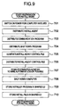
Fig. 9 is a flowchart showing the work
process executed in preparation for the install.
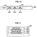
Fig. 10 is a schematic diagram showing an
example of the format of a remote power-on packet.
Fig. 11 is a diagram showing a structure of
an install agent control file.
Fig. 12 is a flowchart showing the flow of
the work for executing the install process.
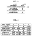
Fig. 13 is a diagram showing a table
structure representing an example a computer status
table file.
Fig. 14 is a diagram for explaining the
definition of the status set in the computer status
table file.
Fig. 15 is a diagram showing the structure of
a computer status table list.
Fig. 16 is a simplified block diagram showing
the configuration of a computer according to a second
embodiment.
Fig. 17 is a diagram showing a format
representing an example of a remote power-on frame.
Fig. 18 is a simplified block diagram showing
the configuration of a computer system according to a
third embodiment.
Fig. 19 is a flowchart showing the flow of
the process executed by an installer program according
to the fourth embodiment.
Fig. 20 is a simplified block diagram showing
the configuration of a computer system according to a
fifth embodiment.
Fig. 21 is a simplified block diagram showing
the configuration of a computer system according to a
sixth embodiment.
DESCRIPTION OF THE EMBODIMENTS
(First embodiment)
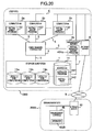
Fig. 1 is a simplified block diagram showing
the configuration of a computer system according to an
embodiment of the invention. The computer system
according to this embodiment comprises a plurality of
computers 2a, 2b,...,2n (hereinafter designated only by
reference numeral "2" for describing these computers
collectively), a storage subsystem 1 shared by the
computers 2, a management console 4 for managing the
computer system, and a fibre channel connector 3 for
connecting the computers 2, the management console 4
and the storage subsystem 1. The computers 2, the
management console 3 and the storage subsystem 1 are
connected with the fibre channel connector 3 by fibre
channels 5. Each computer 2 and the management console
4 are interconnected communicably through a local area
network (LAN) 6. The management console 4 and the
storage subsystem 1 are connected by a communication
path 7.
According to this embodiment, it is assumed
that personal computers (PC) are used as the computers
2. Each computer 2 can of course be a server, a work
station or the like computer. A fibre channel suitable
from the viewpoint of both the connection distance and
the speed is used as an interface (hereinafter referred
to as I/F) for connecting each computer 2 and the
storage subsystem 1. Nevertheless, an interface such
as the smaller computer system interface (SCSI), the
universal serial bus (USB) or the IEEE 1394 bus can
alternatively be used with equal effect.
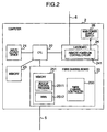
Fig. 2 is a simplified block diagram showing
a configuration of the computer 2. Numeral 21
designates an input/output device for receiving the
input of information or outputting the information,
numeral 22 a central processing unit (CPU) for
controlling the computers 2 as a whole, numeral 25 a
fibre channel board mounted for connecting and
controlling the fibre channel, numeral 24 a LAN board
for performing communication through the LAN 6, and
numeral 23 a memory for storing the programs and data
required by the CPU 22 for executing various control
operations. A plurality of programs are stored in the
memory 23.
The fibre channel board 25 includes a fibre
channel controller 250 for controlling the fibre
channel, and a memory 251 for storing the programs and
data required by the fibre channel controller to
control the fibre channel and the programs and data
required by the CPU 22 to control the fibre channel
controller 250. The programs stored in the memory 251
include a bootup control program for the CPU 22 to
control the fibre channel controller 250 and to load
the OS from the storage subsystem 1 and start it. In
addition to the bootup control program 2511, the memory
251 holds a world wide name (WWN) 2512 constituting
information on the name set forth for uniquely
identifying the fibre channel controller 250.
According to this embodiment, the fibre channel
controller 25 and the memory 251 are arranged on the
board mounted on the computer 2. Nevertheless, these
component parts can alternatively be mounted directly
on the board carrying the CPU 22, etc., for example.
The LAN board 24 includes a remote power-on
circuit 241 for controlling the main power switch 26 of
the computer 2 to switch on/off the power of the
computer 2 from outside of the computer 2.
Fig. 3 is a simplified block diagram showing
the configuration of the storage subsystem 1. The
storage subsystem 1 includes a control unit 11 for
controlling the storage subsystem 1 as a whole, a fibre
channel controller 15 for connecting the fibre channel
5 and controlling the connection, a memory 12 for
storing the programs and data used by the control unit
11 to control the storage subsystem 1, a communication
interface 16 for controlling the communication with the
management console 4, a plurality of logical units (LU)
13a, 13b,...,13n and a shared LU 14. The communication
LU 17 shown is not necessarily required in this
embodiment, as will be explained later with reference
to the second embodiment.
The logical units are a virtual volume
(memory device) recognized by the computer 2, which
recognizes one LU as one logical disk device. The
logical unit is the name defined in the specification
of the SCSI (small computer system interface)
constituting one of the interfaces for connecting the
computer and the storage subsystem. In the SCSI, the
logical unit number (LUN) is attached to each logical
unit as an identifier in order to identify each logical
unit. In the portion of this specification that
follows, the logical unit will be called simply as LU,
and the logical unit number as LUN. A plurality of LUs
can be defined and constructed in the storage subsystem
1. The LU defined in the storage subsystem 1 is called
an internal LU. A serial number which is an integer
beginning with 0 is attached to each internal LU in
order to manage the internal LUs in the storage
subsystem 1. This number is called the internal LUN.
Each computer 2 is assigned a private LU 13
(hereinafter designated by "13" as a reference numeral
whenever the discrimination of each of the logical
units 13a, 13b,..., 13n is not required ) from among a
plurality of LUs defined. In this specification, the
LU 13 assigned to any one of the computers exclusively
is also called a local LU. A LU 14, on the other hand,
is shared and can be accessed by all the computers 2
and the management console 4. The LU shared by a
plurality of computers will be called a shared LU in
this specification. At the time of booting up the OS,
the computer 2 searches the storage subsystem connected
thereto and detects the LUNs thereof. Generally, the
detection of the LUs by a computer such as the PC is
accompanied under the restraints to the effect that (a)
the LUNs are searched from 0 sequentially, and (b) the
LUNs are assumed to exist in serial numbers and in the
absence of a number, the search after the particular
number is not conducted. According to this embodiment,
each computer is caused to recognize a virtual LUN so
that it can recognize only those LUNs of the LUs
available for use in serial numbers beginning with
zero. The LUNs recognized in virtual manner by the
computer 2 will hereinafter be called the virtual LUNs.
The correspondence between the internal LUNs and the
virtual LUNs is managed by the LUN management table
described later.
The memory 12 has stored therein a LU
definition program 121 executed by the control unit 11
for defining and preparing the LUs, an access control
program 123 executed by the control unit 11 for
controlling the access to each LU from each computer 2
and a LUN management table 122 for storing the
management information accessed by the control unit 11
at the time of controlling the access from each
computer to the LUs.
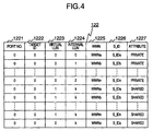
Fig. 4 is a diagram showing a table structure
representing an example of the LUN management table.
The LUN management table 122 has a plurality of entries
each corresponding to a set of an internal LU and a
computer which can use the particular internal LU.
Each entry has set therein a port number 1221, a target
ID 1222, a virtual LUN 1223, an internal LUN 1224, a
WWN 1225, a S_ID 1226 and an attribute 1227. These
information are set through the management console 4 by
the system manager at the time of preparing and
defining the LU, for example.
The port number 1221 is the number attached
to a connecting port of the fibre channel of the
storage subsystem 1. According to this embodiment, the
storage subsystem 1 is assumed to have one connection
port and zero is stored for all the the port numbers
1221.
The target ID 1222 is an identifier assigned
to the storage subsystem 1 in the interface with the
computer 2. In the case where a fibre channel is used
as an interface connecting the computer 2 and the
storage subsystem 1 as in the present embodiment, the
D_ID (destination ID) attached to each port at the time
of initialization can be used as the target ID 1222.
In the case where the SCSI is used as an interface, a
plurality of IDs can be assigned to the same port. In
such a case, the target ID associated with each LUN is
set in this field. In the case where the interface is
a fibre channel, the number and the D_ID of the
connection port can be set in one-to-one relation, and
therefore one of port number 1221 and the target ID
1222 can be done without. According to this
embodiment, the fibre channel is used as an interface,
and therefore it is assumed that the target ID 1221 is
not used and zero is set for all the target IDs 1221.
The virtual LUN 1223 and the internal LUN
1224 hold the relation between the virtual LUN
recognized by the computer 2 identified by the
information set in the WWN 1225 and the internal LUN
corresponding to the particular virtual LUN.
The WWN 1225 has set therein the WWN 2512 set
in the fibre channel controller 250 of the computer 2.
The WWN is the information given from each computer 2
at the time of the port log-in process for establishing
the connection between the fibre channel ports.
The S_ID 1226 is the ID information set in
the frame header of the fibre channel for identifying
the source (initiator) that has prepared the frame.
The S_ID is dynamically assigned at the time of
initialization of the fibre channel. By relating WWN
and S_ID to each other, the computer 2 can be specified
by checking the S_ID without referring to WWN for each
frame.
The attribute 1227 indicates the property of
each LU. The word "private" indicates a LU assigned
exclusively to one computer 2. The word "shared"
indicates the fact a LU is shared by a plurality of the
computers 2.
Assume that WWN of the computer 2a is WWNa
and S_ID thereof is S_IDa, WWN of the computer 2b is
WWNb and S_ID thereof is S_IDb, WWN of the computer 2n
is WWNn and S_ID thereof is S_IDn, and WWN of the
management console 4 is WWNz and S_ID thereof is S_IDz.
From the LUN management table 122 shown in Fig. 4, it
is understood that the computer 2a, for example, is
assigned a LU with an internal LUN of 0 as a private
local LU 13a and recognized as LU of LUN "0". In
similar fashion, it is understood that the computer 2b
is assigned LU with LUN of "1" as a private local LU
and recognized as LU of LUN "0" from the computer 2b.
It is also understood that the LU with the internal LUN
"k" is the one shared by a plurality of computers and
recognized as LU with LUN "1" from the computers 2a,
2b, 2n and as LU of "0" from the management console 4.
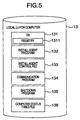
Fig. 5 is a diagram for explaining the
programs, etc. stored in the local LU 13. The local LU
13 has stored therein the programs used by the computer
2 assigned the particular LU including an operating
system (OS) 131, an install agent program (hereinafter
referred to as the install agent) 132, a communication
program 134 and a shutdown program 135. These programs
are loaded in the memory 23 of the computer 2 and
executed by the CPU 22.
The OS 131 is a program for executing various
programs and controlling the hardware on the computer
2, and includes a registry 1311 for holding and
managing the information on the setting and structure
of the OS 131, the information on the programs executed
by the computer 2 and the information on the user
utilizing the particular computer 2. The install agent
132 is a program for starting the installer for
installing a program and performing a part or the whole
of the install work on behalf of the operator who has
thus far conducted it. The communication program 134
is for controlling the communication with the
management console 4 and reporting the progress of the
install work and the occurrence of an error. The
shutdown program 135 is for shutting down the computer
2.
In addition to the programs described above,
the local LU 13 has stored therein an installer agent
control file 133 holding the information for
controlling the install agent 132, and a computer
status table file 136 holding the information on the
progress of the work for installing the program
executed in the computer 2 and various status
information including the success/failure of the work.
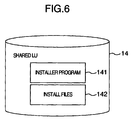
Fig. 6 is a diagram for explaining the
program, etc. stored in the shared LU 14. The shared
LU 14 has stored therein a program installer 141 and
install files 142. The install files 142 include the
files required for installing such as various setting
files and the file for the program installed by the
installer 141. The installer program 141 and the
install files 142 are copied to the shared LU 14 from a
removable medium such as a CD-ROM by the operator prior
to the install work.
The installer program 141 is executed by
being loaded in the memory 23 of the computer 2 by the
install agent 132. The install files are accessed by
the installer program 141 or copied to the local LU 13
of the computer 2 executing the installer program 141.
Fig. 7 is a simplified block diagram showing
a configuration of the management console 4. The
management console 4 includes an input/output device 41
by way of which the manager operates the management
console 4, a CPU 42 for controlling the whole
management console 4, a memory 43 for storing the
program executed by the CPU 41 and the related data, a
fibre channel board 45 for connecting and controlling
the fibre channel 5, a LAN board 44 for performing the
communication through the LAN 6, a disk unit 46 for
storing the OS and the program for the management
console 4 and a communication interface 47 for
establishing communication with the storage subsystem
1.
The programs stored in the memory 43 include
an install manager program (hereinafter referred to as
the install manager) 431 for controlling the install
work in general. The install manager 431 includes a
plurality of subprograms described below.
Fig. 8 is a schematic diagram showing a
structure of the install manager 431. The install
manager 431 includes a remote power control program
4311, an install agent control file distribution
program 4312, an install agent distribution program
4313, a registry modification program 4314, a shutdown
program distribution program 4315, a progress display
program 4316, a communication program 4317 and a
communication program distribution program 4318.
The remote power control program 4311 is for
controlling the on/off state of the power supply and
the rebooting of the computer 2 from a remote place.
The install agent control file distribution program
4312 is for distributing the install agent control file
133 to each computer 2. The install agent distribution
program 4313 is for distributing the install agent 132
to each computer 2. The registry modification program
4314 is for altering the registry 1311 of the computer
2 from a physically distant place. The shutdown
program distribution program 4315 is for distributing
the shutdown program 135 to each computer 2. The
progress display program 4316 is for displaying the
progress of the install work and the error that may
occur in each computer 2. The communication program
4317 is for acquiring the information on the occurrence
of an error and the progress of the install work by
communication with each computer 2. The communication
program distribution program 4318 is for distributing
the communication program 134 to each computer 2.
Fig. 9 is a flowchart of the process executed
in preparation for the install work.
The operator first switches on the power
supply of the computer 2 in which a program is to be
installed. Specifically, the install manager 431 of
the management console 4 is started, and a remote
power-on packet is prepared by the remote power control
program 4311 and transmitted to the particular computer
2. The remote power-on packet, as an example of the
format thereof is shown in Fig. 10, includes a header
901 and a data section 902. The data section 902
includes a sync field 9021 and one or a plurality of
MAC addresses 9022 of the computer 2 for which the
power supply is switched on. The remote power-on
control means 241 on the LAN board 24 of the computer
2, upon receipt of the remote power-on packet 900,
checks the MAC addresses 9022 set in the data section
902. The remote power-on control means 241 compares
the MAC addresses 9022 set in the data section 902 with
the MAC address of the LAN board 24, and in the case
where there is a coincident address, controls the main
power switch 26 thereby to switch on the power supply
of the computer 2 (step 701).
Once the power supply for the computer 2 in
which a program is to be installed is switched on, the
install manager 431 executes the install agent program
distribution program 4313 and distributes the install
agent 132 to each computer 2 through the LAN 6. Each
computer, upon receipt of the install agent 132, stores
it in a private local LU 13. The programs distributed
to the computer 2 in this or subsequent steps can be
stored in the local LU 13 of each computer 2 directly
from the management console 4 by mounting such a local
LU 13 as a network disk in the management console 4
(step 702).
Then, the install manager 431 distributes to
each computer 2 the communication program 134 by the
communication program distribution program 4318 and the
shutdown program 135 by the shutdown program
distribution program 4315. These programs are stored
in the local LU 13 like the install agent 132 (steps
703, 704).
Then, the install manager 431 generates an
install agent control file 133. Fig. 11 shows the
structure of the install agent control file 133. The
install agent control file 133 contains such
information as a select installer 1331, an agent on/off
identifier 1332, an installer start time 1333 and
install key information 1334. The select installer
1331 indicates the place of storage and the name of the
installer program 141 to be started by the computer 2.
This information permits the computer 2 to perform the
control operation as to which one of a plurality of, if
any, the installer programs 141 is to be started. The
agent on/off identifier 1332 is used for determining
whether the install agent 132 of the computer 2
executes the install process or not. The agent on/off
identifier 1332 contains the description of an on-attribute
or an off-attribute. The installer start
time 1333 is information for indicating the time for
starting the installer program 141 to the install agent
132. The install key information 1334 is prepared for
preventing an illegal installation. The install agent
132 executes the install work only when proper key
information is stored. This information is used as
required and not essential. The contents of the
install key information 1334 will be described later
(step 705).
The install manager 431 distributes to each
computer 2 the install agent control file 133 according
to the install agent control file distribution program
4312. This file, once distributed to each computer, is
stored in the local LU 13 of the particular computer 2
(step 706).
Upon complete distribution of each program
and the install agent control file, the install manager
431 modifies the registry 1311 of the computer 2
according to the registry modification program 4314 in
such a manner that the computer 2 is automatically
logged on and starts executing the install agent 132
(step 707). Then, the install manager 431 starts the
shutdown program 135 of the computer 2 and shuts down
the computer 2 according to the remote power control
program 4311 (step 708).
After shutting down the computer 2 in which a
program is to be installed, the install manager 431
stores the installer program 141 and the install files
142 in the shared LU 14 (steps 709, 710).
The preparatory work for installation is thus
completed.
Fig. 12 is a flowchart showing the flow of
the process executed for the install work.
The operator operates the management console
4, like in step 701, to start the install manager 431
and switch on the power supply of the computer 2 for
the install work according to the remote power control
program 4311 (step 801).
Once the power supply is switched on, each
computer 2 starts the OS 131 and is automatically
logged on. Upon activation, the computer 2 starts
executing the install agent 132. According to this
embodiment, once the OS 131 is started, the install
agent 132 is automatically started to start the work.
It is also possible, however, to implement the install
agent 132 as a program resident in the computer 2. In
this case, the install agent 132 is instructed to start
the operation from the install manager 431 by the
inter-program communication (step 802).
The install agent 132 of the computer 2, once
the operation is started, accesses the install agent
control file 133 in the local LU 13 for the computer
(step 803).
The install agent 132 checks the agent on/off
identifier 1332 of the install agent control file 133.
In the case where the agent on/off identifier 1332
indicates the on-attribute, the install key information
1334 is ascertained. The install key information 1334
can be, for example, the license key information issued
by the developer of the program installed or the
license key information issued by the developer of the
install manager and the install agent. The use of
these information makes it possible to check whether
the program to be installed has legitimately received a
license or not. It is also possible to use as the
install key information 1334 the ID information such as
the WWN or MAC address of the computer permitted for
installation. The install agent 132 compares these
information with the ID information on the computer and
thus can determine whether the particular computer is
permitted for installation or not. These ID
information for the computer and the license key
information described above can be used in combination
as the install key information 1334. In the case where
the agent on/off identifier 1332 is the off-attribute
or the install key information 1334 is not valid, the
install agent terminates the process without installing
the program (step 804).
In the case where the agent on/off identifier
1332 is the on-attribute and the install key information
1334 is valid, on the other hand, the install
agent 132 starts by loading in the memory 23 the
installer program 141 stored in the shared LU. In the
case where the time to start the installer program is
designated by the installer start time 1333 of the
install agent control file 133 in step 804, however,
the install agent 133 withholds the starting of the
installer program till the designated time.
The installer program 141, once started,
installs the program. In the process, in order to
reflect the install information in the registry 1311 of
the computer 2, the installer program 141 reads the
install files 142 into the memory 23 of the computer 2
through the fibre channel from the shared LU 14, and
transfers the files to the local LU 13 (step 806).
Upon completion of the install process by the
installer program 141, the install agent 132 rewrites
the agent on/off identifier 1332 of the install agent
control file 133 to the off-attribute so that the
install process may not be performed at the time of
next activation of the computer 2. At the same time,
the install key information 1334 is invalidated as
required (step 807).
Then, the install agent 132 starts the
shutdown program 135 in the local LU 13 (step 808).
The shutdown program 135, once started, shuts down the
computer 2 (step 809).
Thus, the install work is completed. After
that, upon activation of the computer 2 by the user,
the installed program can be used. In the case where a
program is installed in a plurality of computers 2, the
preparatory work described above is carried out for the
computers, and the power supply of the computers 2 is
switched on in step 801. Then, the install process is
performed in parallel on the computers.
In the program install work, the operator can
desirably check how the install process is proceeding
and whether the work has been completed without any
error or not. According to this embodiment, the
progress of the install work and the occurrence of an
error are recorded in the computer status table file
136, and this file is accessed from the management
console 4. Thus, the operator can check the progress
and the occurrence of an error.
Fig. 13 is a diagram showing a table
structure representing an example of a computer status
table file 136. The computer status table file 136, as
shown, has recorded therein the information indicating
the work condition in the computer 2 including the
power supply condition, the OS starting conditions, the
operation of the install agent, the condition of the
install process and the shutdown process. The computer
status table file 136 has sequentially recorded therein
the progress and the error occurrence for each work
step during the install work. Specifically, the power
supply condition and the OS starting condition are
recorded according to the remote power control program
4311, the install agent condition and the install
condition according to the install agent 132, and the
shutdown condition according to the shutdown program
135. The value set as the status 1362 is defined as
shown in Fig. 14. According to the definition of Fig.
14, it is understood from the computer status table
file 136 shown in Fig. 13 that the shutdown process of
the computer 2 is not started by this computer upon
completion of the OS starting process, during the on
state of the install agent or during the execution of
the install process while the power supply is on.
The management console 4 mounts the local LU
13 as a network disk, reads the computer status table
file 136 stored in each local LU 13 according to the
progress indication program 4316, and displays on the
input/output device 41 the work progress and the error
occurrence in the computer 2 intended for install work.
According to this embodiment, the computer status table
file stored in the local LU 13 is accessed directly
from the management console 4. As an alternative, the
same information can be transferred by communication
between the communication program 134 of each computer
2 and the communication program 4317 of the management
console 4. In the case where an error occurs during
the install work, the operator can recognize it on the
management console 4, and can take the necessary action
including the retrial.
According to this embodiment, a program can
be installed using a fibre channel constituting a high-speed
interface without the intermediary of a control
unit such as a file server between the computer and the
storage subsystem. As a result, the file transfer
executed for the install process can be increased in
speed. Also, a program can be installed in a plurality
of computers in parallel at a time by one operator from
the management console. As a result, the install time
and the number of operators required can be reduced,
thereby making it possible to reduce the operation cost
for maintaining and managing the computer system.
Further, in view of the fact that the management
console can be located at a place physically distant
from the place of the computer and the install work can
be performed by remote control, the operator is not
required to enter the environment in which the computer
exists, and thus the security of the computer system
can be improved. Furthermore, the use of the install
key information prevents the illegal or erroneous
install work of the computer which has not yet obtained
the license. In addition, according to this
embodiment, the install work can be conducted in the
same procedure without regard to the type of the
program installed, and therefore the install work is so
simplified that a special knowledge or skill is not
required for the install work.
According to this embodiment, the illegal or
erroneous install work is prevented by the install
agent control file. As an alternative, prior to
carrying out the install work, the local LU of the
computers other than the computer intended for the
install work is hidden or the shared LU is hidden from
the computers other than the computer intended for the
install work, so that the install work for the
computers other than the intended computer cannot be
carried out using the function of the LUN management
table 122 of the storage subsystem 1. Further, the
illegal or erroneous install work can be prevented by
deleting the installer program and the install files
from the shared LU after completion of the install
work.
(Second embodiment)
Unlike in the first embodiment in which the
power on control operation of each computer is
performed through a LAN, a similar process can be
executed without using the LAN. An explanation will be
given of a second embodiment in which the install work
is conducted without using the LAN.
The computer system according to the second
embodiment is basically configured similarly to the
computer system according to the first embodiment
except that the LAN 6 is not required for the second
embodiment. The explanation below, therefore, will be
given with reference to the drawings used for
explaining the first embodiment.
According to this embodiment, a communication
LU 17 is included in the storage subsystem 1. A
computer status table list indicating the status of
each computer 2 is held in the communication LU 17.
Fig. 15 is a diagram showing a structure of a
computer status table list 137. The computer status
table list 137 is a summary of the contents of the
computer status table file 136 of each computer 2. The
contents of the computer status table file 136 are
similar to those shown in Fig. 13. The computer status
table list 137 is used for notifying the management
console 4 of the progress and the error occurrence in
the install work conducted for each computer 2.
The computer status table list 137 is
prepared according to the communication program held in
each computer 2. In the table 1371 for each computer
2, an address in the communication LU 17 is uniquely
determined in advance. The communication program 134
of the computer 2 is used for accessing the
communication LU 17 using a RAW I/O command for
directly reading/writing the logical block of the LU
but not the file read/write operation using the file
system. As a result, the status information can be
written in the computer status table list 137 at an
arbitrary timing by each computer 2. Also, the
communication program 4317 constituting a subprogram of
the install manager 431 of the management console 4
makes it possible to grasp the status of each computer
2 from time to time by reading the computer status
table list 137 at an appropriate timing using the RAW
I/O command. According to the communication program
4317 of the management console 4, data cannot be
written in the computer status table list 137 unless it
is clear that the install work is not yet carried out
or has already been carried out for a given computer.
In the case where the files can be shared by the file
systems, the computer status table 136 can be accessed
without using RAW I/O by constructing it as a file.
According to this embodiment, the various
programs and files are distributed in the process of
preparation for the install work as follows.
In this embodiment, the management console 4,
like in the preparation and definition of LU, changes
the WWN of the LUN management table 122 of the storage
subsystem 1 by communication with the storage subsystem
1, and mounts on the management console 4 the local LU
13 of the computer 2 in which a program is to be
installed. Under this condition, the management
console 4 stores various programs and files in the
local LU 13 of each computer 2. After storing the
programs and files, the management console 4 restores
the information in the LUN management table 122 to make
the files thereof available for the next activation of
the computer 2.
According to this embodiment, the power-on
control of the computer 2 is carried out through a
fibre channel. Each computer 2, therefore, as shown in
Fig. 16, includes a remote power-on control means 2501
and a standby power supply 2502 on the fibre channel
board 25. The LAN is not used in this embodiment, and
therefore, the LAN board is not shown in Fig. 16.
Nevertheless, the LAN board may be provided for other
purposes.
The remote power-on control means 2501 is
arranged in the fibre channel controller 250. The
standby power supply 2502 is maintained in on state for
supplying power to the fibre channel board 25 even
while the main power supply of the computer 2 is in off
state. Thus, the fibre channel controller 250 is
operable and can receive the frames (packets) sent
through the fibre channel 5 regardless of the state of
the main power supply of the computer 2.
Fig. 17 is a diagram showing the format of an
example of the remote power-on frame used for switching
on the computer 2. The frame of the fibre channel
includes a SOF (start of frame) 9501 indicating the
head of the frame, a frame header 9502 having such
information as the transmission node of the frame and
the frame type, a payload 9503 for holding the entity
of the data transferred by the frame, a CRC (cyclic
redundancy code) 9504 constituting a data guarantee
code for detecting a bit error of the frame and an EOF
(end of frame) 9505 indicating the tail end of the
frame. The remote power-on frame 950 includes a
broadcast identifier 9502a in the frame header 9502.
The broadcast identifier 9502a indicates that the frame
involved is the one issued at the same time to all the
nodes connected to the fibre channel. As a result, the
remote power-on frame 950 is transferred to all the
devices on the fibre channel. The payload 9503 has set
therein the WWN attached to the fibre channel
controller 250 of the computer 2 for which the power
supply is switched on.
In order to switch on the power supply of the
computer 2 for which a program is to be installed in
step 801 of the install process, the install manager
431 of the management console 4 prepares the remote
power-on frame 950 described above according to the
remote power control program 4311. The payload 9503 of
the remote power-on frame 950 thus prepared has set
therein the WWN of at least one computer 2 for which a
program is to be installed. The remote power-on frame
950 thus generated is broadcast on the fibre channel.
The remote power-on frame 950 thus broadcast
is received by the fibre channel controller 250 of each
computer 2. The fibre channel controller 250, upon
receipt of the remote power-on frame 950, inspects the
frame header 250 thereof. In the case where the frame
header 2502 contains the broadcast identifier 9502a,
the payload 9503 is further inspected to check whether
the WWN coincident with the WWN of its own is set or
not. In the case where the WWN coincident with its own
WWN is set in the payload 9503, the fibre channel
controller 250 switches on the power supply of the
computer 2 by controlling the main power supply switch
26 by the remote power-on control means 2501.
According to this embodiment, the install
process is performed basically in a similar manner to
the first embodiment except that the method of
distribution of the programs and files and the method
of remote power-on of the computer 2 are different.
In this embodiment, the power-on control of
the computer is performed through the fibre channel and
the communication is established between the computer
and the management console through the communication LU
17, and therefore the install work can be carried out
by remote control even in an environment lacking the
LAN. Although this embodiment uses the broadcast frame
of the fibre channel for power-on control, the remote
power-on can be realized by transferring a remote
power-on packet through the fibre channel like in the
first embodiment as long as he fibre channel controller
corresponds to the IP protocol.
(Third embodiment)
According to the first and second
embodiments, the computer 2 reads the install files
from the shared LU 14 and transfers them to its own
local LU 13 at the time of program install work. Now,
an explanation will be given of the "direct install" in
which the install work is carried out by transferring
the install files without the intermediary of the
computer 2.
Fig. 18 is a simplified block diagram showing
a configuration of a computer system according to this
embodiment. In Fig. 18, those component parts similar
to the corresponding parts of the first embodiment are
designated by the same reference numerals as in Fig. 1,
respectively. The difference of this embodiment from
the first embodiment will be mainly explained below.
The computer 2 has the function of a direct
copy director 138 for giving a copy instruction to the
storage subsystem 1 and the function of a direct copy
API 137 which is an application program interface (API)
for giving a copy instruction from the program to the
direct copy director 138. These functions are stored
in the private local LU 13 of each computer 2, and at
the time of execution, loaded on the memory 23 and
realized by the program executed by the CPU 22.
The storage subsystem 1 has a direct copy
engine 124 for copying data to the destination LU from
the source LU in the storage subsystem 1 in response to
an instruction from the direct copy director 138. The
direct copy engine 124 is stored in the memory 12 of
the storage subsystem 1 and realized as a program
executed by the control unit 11.
Fig. 19 is a flowchart showing the flow of
the process executed by the installer program 141
according to this embodiment. The installer program
141, once the process is started, displays the title on
the input/output device 21 or otherwise executes the
initialization of the install screen (step 851). The
installer program 141 then displays a screen for
prompting the input of the user information and the
license information of the program on the input/output
device 21 and waits for the input of these information.
Normally, the license information, etc. are input by
the operator. According to this embodiment, however,
like in the first embodiment, the install agent 132
performs this process on behalf of the operator (step
852). Then, the installer program 141 receives the
input of selection of the install method. The install
method designated in this case includes, for example, a
standard install based on a predetermined file
structure and setting or a custom install in which the
type and structure of the program installed and the
file can be set arbitrarily (step 853). The installer
program 141 and the directory of the installee for
storing the program to be installed are designated
(step 854). The input process performed in these steps
852, 853, 854 are also performed by the install agent
132 on behalf of the operator. The install agent 132
inputs the various information described above into the
installer program 141 in accordance with the
information set in the install agent control file.
Based on the information set in the foregoing
steps, the installer program 141 specifies the file to
be copied and the directory of the installee and
executes the processing of copying the file. The file
copy process is executed by calling the direct copy API
137 from the installer program 141. The direct copy
API 137 is given as a function described, for example,
as "direct_file_copy (transferor and transferee)" on
the source code of the installer program 141. In the
case where the file "file 1" of the directory "dir_a"
of the shared LU (assume a d drive) is copied to the
directory "dir_b" of the private LU (assume a c drive),
for example, "direct_file_copy(d;dir_a¥file 1,
c;dir_b);" is described on the source code. In
accordance with the parameter thus given, the direct
copy API 137 instructs the storage subsystem 1 to copy
the file through the direct copy director 138. The
transfer of the file designated in accordance with this
instruction is executed in the storage subsystem 1
(step 855).
Upon completion of copying all the required
files, the installer program 141 executes the process
for registration of the registry 1311 of the OS 131
(step 856). The install work is thus completed. After
that, the installer program 141 reboots the computer as
required. Also, the install agent 132, like in the
first embodiment, executes the process for changing the
setting of the install agent control file 133 as
required thereby to complete the install process (step
857).
Now, the direct copy performed in step 906
will be explained in detail. The direct copy API 137,
after being called by the installer program 141,
transfers the process to the direct copy director 138.
The direct copy API 137, without performing any
specific process, exchanges the process between the
direct copy director 138 and the application programs
such as the installer program 141. The direct copy
director 138, upon receipt of a direct copy request
from the direct copy API 137, specifies the LU from the
drive letter delivered thereto as a parameter, and
based on the directory and file name of the source and
the destination, the copy information including a pair
of the logical address and the transfer length of the
source and the destination is produced with reference
to the file table information of the OS 131 generally
called the file system. The copy information can be
structured so that a plurality of file transfers can be
requested as a list at a time. The direct copy
director 138 issues the copy information list to the
direct copy engine 124 of the storage subsystem 1. The
direct copy engine 124, upon receipt of the copy
information list from the direct copy director 138 of
the computer 2, accesses the LUN management table 122
and acquires the internal LUN from the virtual LUN of
the source and the destination, respectively. Then,
the direct copy engine 124 generates a read command
from the logical address and the transfer length of the
source and a write command from the logical address and
the transfer length of the destination by reference to
the copy information list. The direct copy engine 124
executes the read command and the write command
sequentially in the storage subsystem using the access
control program. The data read in response to the read
command is temporarily held in a buffer (or cacher) not
shown in the storage subsystem 1. The data thus held
in the buffer is written in the LU of the copy in
response to the write command. The direct copy engine
124 executes the foregoing process for all the copy
information in the order specified in the copy
information list. Upon completion of all the copying
process based on the copy information, the direct copy
engine 124 reports the termination of the process to
the direct copy director 138 of the computer 2.
According to this embodiment, the file
copying process can be executed in the storage
subsystem 1 at the time of the install work. As a
result, the computer processing accompanying the
copying process and the data transfer by the fibre
channel are done without, so that the processing load
of the computer and fibre channel for the install
process can be reduced. Also, in view of the fact that
a quicker copying process can be realized by the data
copying in the storage system 1, the time required for
the install process can be shortened.
According to the third embodiment, the direct
copy engine 124 is arranged in the storage subsystem 1.
As an alternative, the direct copy engine 124 can be
arranged in the fibre channel connector 3. In the
latter case, the fibre channel connector 3 generates a
read command and a write command for copying and issues
them to the storage subsystem 1. Also, the fibre
channel connector 3 is required to hold the data
temporarily and therefore is required to have an
internal buffer. This configuration, although data
flows in the fibre channel, can reduce the load on the
computer like in the third embodiment described above.
Further, there is no need of a special function of the
storage subsystem 1 and a system can be configured of
the conventional storage subsystem. Furthermore, the
direct install work can be executed also in the case
where the source LU and the destination LU are stored
in storage subsystems physically different from each
other.
(Fourth embodiment)
The third embodiment utilizes the one-to-one
direct copying process from one source to one
destination for the copying process for the install
work. According to this embodiment, on the other hand,
the copying from one source to a plurality of
destinations is carried out without the intermediary of
the computer 2. This direct copy from one source to a
plurality of destinations is called "the one-to-n
direct copy".
According to this embodiment, as shown in
Fig. 18, a direct copy destination LU link generation
program 125 is arranged in the storage subsystem 1.
The direct copy destination LU link generation program
125 relates (links) a plurality of LUs constituting
copy destinations to each other. Once a link is
generated by the direct copy destination LU link
generation program 125, the direct copy engine 124
carries out the one-to-n copying process in response to
one copy request from the computer 2. This function
permits the same program to be installed in a plurality
of LUs forming a link as an internal process of the
storage subsystem 1 by carrying out the install process
for any one LU from the computer 2.
The operator or the manager designates the
LUs (assume that the link is formed for LU-a, LU-b, LU-c,
for example) linked to the storage subsystem 1 by
the install manager 431. In the process, one LU is set
as a representative LU. Assume that LU-a is a
representative in the case under consideration. The
direct copy destination LU link generation program 125
of the storage subsystem 1 forms a link for the
internal LU-a, LU-b, LU-c.
While the direct copy process is executed,
the direct copy director 138 of the computer 2
generates a copy information list and transmits it to
the storage subsystem 1. The direct copy engine 124 of
the storage subsystem 1, upon receipt of the copy
information list, accesses the LUN management table
122, determines the internal LUN from the virtual LUN
of the copy source and the copy destination,
respectively. In the copy information list, only the
representative LU is designated as a copy destination.
The direct copy engine 124 accesses the copy
information list, so that a read command is generated
from the logical address of the source and the transfer
length and a write command of the same contents for all
the LUs (LU-a, LU-b, LU-c) for which a link is formed
from the logical address of the copy destination and
the transfer length. Then, the direct copy engine 124
executes the read command using the access control
program and reads the data temporarily into the buffer
in the storage subsystem 1. After that, the data read
into the buffer is written in a plurality of LUs linked
by the write command.
The process described above makes it possible
to install a program in a plurality of LUs at a time.
Also, according to this embodiment, like in the third
embodiment, the direct copy engine 124 and the direct
copy destination LU link generation program 125 can be
arranged in the fibre channel connector 3 thereby to
realize these processes as a function of the fibre
channel.
Also, according to this embodiment, a
plurality of copy destination LUs are designated in
advance by the direct copy LU link generation program
125. As an alternative, the functions of the direct
copy API can be expanded thereby to use the API for
realizing the one-to-n direct copy. Such an API can be
described as a function such as "direct_file_copy_n
(number of copy destination LUs, transferor, transferee
1, transferee 2,...., transferee n);". In this case,
the direct copy director 138 transmits information on a
plurality of the LUs linked as a part of the copy
information list to the direct copy engine 124. As a
result, the 1-to-n direct copy can be realized without
link designation in advance.
(Fifth embodiment)
In the first to fourth embodiments described
above, the storage subsystem 1 is connected to the
management console 4 through the fibre channel 5.
Therefore, the management console 4 and the storage
subsystem 1 cannot be arranged beyond the distance
connectable by the fibre channel. Under the
circumstances, the connectable distance of the fibre
channel is 10 km, and in each of the embodiments
described above, a program cannot be installed from a
remote place farther than this distance. □
A method of realizing the program install work from a
farther place will be explained below as a fifth
embodiment. Fig. 20 is a simplified block diagram
showing a configuration of a computer system according
to the fifth embodiment. In Fig. 20, a user site 1000
having a computer system comprising computers 2 for
which a program is to be installed and a management
site 2000 where a manager performs the install
operation are arranged at physically distant places
from each other.
A computer system basically similar to that
of the first embodiment is arranged in the user site
1000. The computer system in the user site 1000 is
different from the computer system according to the
first embodiment in that it comprises a management
server 4a in place of the management console 4 and an
internet server 8 is connected to a LAN 6. On the
other hand, a management console 4b and an internet
server 10 connected to the management console 4b are
arranged in the management site 2000. The internet
server 8 and the internet server 10 are connected to
each other communicably through an internet 9
constituting a wide area network.
The management server 4a in the user site
1000 is basically similar to the management console 4
according to the first embodiment, and is operated from
the management site 2000 through the internet 9. An
install manager server program (hereinafter referred to
as the install manager server) 431a has the function as
a server for the management console 4b of the
management site 2000 in addition to the function as the
install manager 431 according to the first embodiment.
The management console 4b is a terminal device such as
a PC which communicates with the management server 4a
through the internet 9, displays various operation
screens or operates on a browser program (hereinafter
referred to as the browser) 432b for receiving the
various operations of the manager.
The remaining component parts of this
embodiment are similar to the corresponding parts of
the first embodiment and will not be explained below.
Now, the install process according to this
embodiment will be explained primarily with reference
to the difference from the first embodiment. Assume
that the various settings of LU have been completed and
the install manager server 431a is already operating on
the management server 4a.
Before installing the program, the required
files are transferred to the management server 4a in
advance from the management site 2000. The required
files include the install agent 132, the install agent
control file 133, the communication program 134, the
shutdown program 135, the installer program 141 and the
install files 142. These files are transferred using a
transfer protocol such as the file transfer protocol
(ftp). These files are stored temporarily in the local
disk device of the management server 4a. The manager
sets various data in the install agent control file 133
for each computer using the management console 4b in
advance.
The program install operation is performed by
activating the browser 432b on the management console
4b and accessing the install manager server 431a
through the internet 9. The specific contents of the
process performed for the install work are similar to
those of the first embodiment shown in Figs. 9 and 12
except that the operation of the install manager server
on the management server 4a is performed through the
internet.
While the program is being installed, the
management server 4a accesses the computer status table
file 136 of each computer 2. Thus, the progress of the
work and the error occurrence in each computer 2 in
which a program is being installed are transmitted to
the management console 4b through the internet 9
according to the progress display program 4316. The
work progress and the error occurrence sent by the
browser 432b are displayed on the display unit of the
management console 4b.
According to this embodiment, there is no
restraint of the physical distance between the
management console operated by the manager and the
place where the computer in which the program is to be
installed is located, and the install work can be
realized by centralized control from a remote place.
Also, the configuration of the user site 1000 and the
install work according to this embodiment, which are
similar to those of the first embodiment, can be based
on the corresponding user site and the install work of
the second to fourth embodiments with equal effect.
(Sixth embodiment)
The fifth embodiment described above refers
to a method for the activation control and the
management of the monitoring of the progress of the
install work from a remote place. A sixth embodiment
will be explained below, on the other hand, by
referring to the case in which the centralized file
transfer for the install work is carried out from a
remote place.
Fig. 21 is a simplified block diagram showing
a configuration of a computer system according to the
sixth embodiment. A user site 1001 and a management
site 2001 are arranged at places physically distant
from each other. A computer system having computers in
which a program is to be installed is arranged in the
user site 1001. The computer system of the user site
1001 has a configuration similar to that of the first
embodiment. The storage subsystem 1a of the user site
1001, however, has the remote copy function 126
described later in addition to the functions of the
storage subsystem 1 in the first embodiment. The
management site 2001 includes an agent computer 132x, a
storage subsystem 1b and a management console 4c. The
agent computer 132x, the storage subsystem 1b and the
management console 4c are interconnected through a
fibre channel connector 3. The storage subsystem 1b
included in the management site 2001 has a
configuration similar to the storage subsystem 1a. The
storage subsystem 1a and the storage subsystem 1b are
interconnected through a broad band communication path
9a implemented by a network such as an internet, a
public telephone network, an ATM network or a fibre
channel. The storage subsystem 1a and the storage
subsystem 1b, which are connected directly in Fig. 21,
may alternatively be connected through a connector such
as a gateway or a router.
The remote copy function 126 is for
transferring the data to other storage subsystems
through the broad band communication path 9a. Once
data is written in the storage subsystem 1b of the
management site 2001 from the management console 4c,
for example, the write data is stored in the disk unit
(LU) in the storage subsystem 1b while at the same time
transferring the same write data to the storage
subsystem 1a of the user site 1001 through the broad
band communication path 9a by the remote copy function
126. The storage subsystem 1a, on the other hand,
receives the write data by the remote copy function
126, writes the same write data in the corresponding
disk unit (LU) in the storage subsystem 1a and
transmits a termination report to the storage subsystem
1b. The storage subsystem 1b returns the termination
report to the management console 4c at the time point
when the write process is complete in the storage
subsystem 1b (in the case of synchronous remote copy)
or at the time point when the write process is
completed in both the storage subsystem 1a and the
storage subsystem 1b (in the case of asynchronous
remote copy). Prior to the execution of remote copy,
the corresponding LUs of the storage subsystems 1a, 1b
are required to be determined in pairs. Also, prior to
the execution of the write process, the initial copy
operation is required to be executed for completely
copying the data in one LU to the other LU in order to
match the data. These control operation and data
transfer are all carried out by the remote copy
function 126.
The install process utilizing the remote copy
function will be explained below. For facilitating the
understanding, it is assumed that a program is
installed in a single computer 2. In the description
that follows, it is also assumed that the LU
configuration of the storage subsystems of the user
site 1001 and the management site 2001 are the same and
each constitute a pair with a corresponding LU.
In preparation for the install work according
to this embodiment, the contents of a local LU 13 for
the computer 2 for which the install work is intended
are copied to a corresponding LU 13 (hereinafter
referred to as the mirror LU) in the storage subsystem
1b so that both the contents may coincide with each
other. The mirror LU of which the contents have
coincided is mounted on the agent computer 2x as a
local LU. The install manager 431 of the management
console 4c, like in the 14th embodiment, distributes
various files to the shared LU 14 of the storage
subsystem 1b of the management site 2001 and the local
LU (mirror LU) of the computer 2x. In distributing the
files, a write access occurs to the shared LU and the
mirror LU in the storage subsystem 1b. In the process,
the remote copy function 126 of the storage subsystem
1b transfers the data to the corresponding LU in the
storage subsystem 1a of the user site 1001. As a
result, the result of file distribution in the
management site 2001 is reflected in the storage
subsystem 1a of the user site 1001.
In executing the install work, a program is
installed in the local LU 13 (mirror LU) using the
agent computer 2x by the management site 2001 like in
the first embodiment. As in the preparatory work
described above, the data written in the mirror LU by
the install process is written in the local LU 13 of
the user site 1001, with the result that a program is
installed in the computer 2 of the user site 1001. The
coincidence of data between the storage subsystem 1a
and the storage subsystem 1b is guaranteed by the
remote copy function 126, and therefore once the
install work in the management site 2001 is successful,
it follows that the install work in the user site 1001
also succeeds.
As described above, according to this
embodiment, the install work including the file
transfer as well as various setting can be carried out
from a remote place. If the setting for individual
computers is required in the user site, it can be done
using the same method as in the fifth embodiment.
Also, it is possible to prepare in the management site
a plurality of agent computers corresponding to a
plurality of the computers for which a program is to be
installed in the user site, and the install work can be
conducted using the agent computers. The install work
for a plurality of computers can also be performed in
parallel.
Further, by application of the one-to-n
direct install process described in the fourth
embodiment, a plurality of computers can be installed
by one agent computer. In similar fashion, by
performing the remote copy process between the storage
subsystem of the management site and the storage
subsystems of a plurality of user sites, the install
process for a plurality of user sites can be performed
at the same time by the install work in a single
management site. However, these methods, according to
which the initial copy cannot be accomplished for all
the LUs, are effective in the case where the
coincidence of the contents of all the LUs is desired
such as for the new system install work including the
OS.
Furthermore, according to this embodiment,
the install process is executed using the remote copy
function. It is possible, on the other hand, to
implement the install work by copying, as a repeated
initial copy, the contents of the LU of the management
site to the LU of the user site after rendering the
contents of the LUs of the user site and the management
site to coincide with each other. Also, for
simplifying the management site, the management site
may be configured with an agent computer and a storage
subsystem connected thereto. In such a case, a program
is installed in the agent computer of the management
site by the same method as in the prior art, thereby
making it possible to realize the work of installing a
program in the computers in the user site using the
remote copy function.
It will thus be understood from the foregoing
description that according to this invention, there is
provided a computer system in which a program can be
installed in the computers efficiently for a reduced
operation cost required for maintenance and management
of the computer system.