EP1085706A2 - Bridge for IEEE 1394 bus network - Google Patents
Bridge for IEEE 1394 bus network Download PDFInfo
- Publication number
- EP1085706A2 EP1085706A2 EP00111361A EP00111361A EP1085706A2 EP 1085706 A2 EP1085706 A2 EP 1085706A2 EP 00111361 A EP00111361 A EP 00111361A EP 00111361 A EP00111361 A EP 00111361A EP 1085706 A2 EP1085706 A2 EP 1085706A2
- Authority
- EP
- European Patent Office
- Prior art keywords
- transmission
- portal
- reception
- packet
- bus
- Prior art date
- Legal status (The legal status is an assumption and is not a legal conclusion. Google has not performed a legal analysis and makes no representation as to the accuracy of the status listed.)
- Withdrawn
Links
Images


Classifications
-
- H—ELECTRICITY
- H04—ELECTRIC COMMUNICATION TECHNIQUE
- H04L—TRANSMISSION OF DIGITAL INFORMATION, e.g. TELEGRAPHIC COMMUNICATION
- H04L12/00—Data switching networks
- H04L12/28—Data switching networks characterised by path configuration, e.g. LAN [Local Area Networks] or WAN [Wide Area Networks]
- H04L12/40—Bus networks
- H04L12/40052—High-speed IEEE 1394 serial bus
- H04L12/40058—Isochronous transmission
-
- H—ELECTRICITY
- H04—ELECTRIC COMMUNICATION TECHNIQUE
- H04L—TRANSMISSION OF DIGITAL INFORMATION, e.g. TELEGRAPHIC COMMUNICATION
- H04L12/00—Data switching networks
- H04L12/28—Data switching networks characterised by path configuration, e.g. LAN [Local Area Networks] or WAN [Wide Area Networks]
- H04L12/40—Bus networks
- H04L12/40052—High-speed IEEE 1394 serial bus
- H04L12/40091—Bus bridging
-
- H—ELECTRICITY
- H04—ELECTRIC COMMUNICATION TECHNIQUE
- H04L—TRANSMISSION OF DIGITAL INFORMATION, e.g. TELEGRAPHIC COMMUNICATION
- H04L12/00—Data switching networks
- H04L12/28—Data switching networks characterised by path configuration, e.g. LAN [Local Area Networks] or WAN [Wide Area Networks]
- H04L12/46—Interconnection of networks
- H04L12/4604—LAN interconnection over a backbone network, e.g. Internet, Frame Relay
- H04L12/462—LAN interconnection over a bridge based backbone
Definitions
- the present invention relates to a network bus bridge and a network system using the network bus bridge, and more particularly to a network bus bridge and a network system which are capable of preventing the bus bandwidth use efficiency from being lowered by the transmission delay.
- IEEE1394 bus A network having the IEEE1394 high-speed serial bus (hereinafter simply called the "IEEE1394 bus”) has been paid attention as one of the bus type networks.
- the IEEE1394 bus has a number of characteristic features such as automatic setting of node IDs, hot plug and play, and isochronous mode suitable for transmission of moving-image data, and has been adopted as a bus for transmitting digital image data.
- a root node issues a transmission permission.
- the transmission order of nodes is determined by a procedure called the "BOSS arbitration".
- BOSS arbitration a node called “BOSS” issues the transmission permission. After the node issues the transmission permission, this node is not the BOSS any more, but the node received the transmission permission becomes a new BOSS.
- the BOSS arbitration is one kind of token passing. Not becoming the BOSS by giving the transmission permission to another node corresponds to "tossing a token”, and becoming the BOSS by receiving the transmission permission corresponds to "receiving a token”.
- a different point of the BOSS arbitration from the general token passing is that in the token passing the circulation order of the token is predetermined, whereas in the BOSS arbitration the node becoming the BOSS (receiving a token) is determined each time through competition. Namely, in the BOSS arbitration, a node which does not desire to transmit data does not become the BOSS (i.e., does not receive a token).
- a half-duplex bus type network has advantages that broadcast is easy and the network topology is flexible, but has disadvantages that other nodes cannot transmit data while one node transmits a frame of a packet.
- the period while a node transmits a frame is more precisely "a period from when a frame starts being transmitted to when it becomes that the next frame can be transmitted".
- This period can be generally defined as a period from the time instance when a node starts transmitting a frame to when the transmitted frame extinguishes from a bus. Namely, when the bus is broadened (i.e., the maximum value of a delay between nodes is set large) for long distance transmission, the transmission delay time becomes long.
- a large frame is generally used. Because the influence of the transmission delay can be mitigated as the frame size becomes large, as apparent from the equation [1]. The large frame can therefore suppress the transmission efficiency from being lowered.
- a network using the IEEE1394 bus is one of the half-duplex bus type networks. This network therefore has the characteristics that if the transmission distance is elongated to generate the transmission delay, the bandwidth efficiency lowers.
- the BOSS can transmit a frame. After the BOSS transmits the transmission permission to another node after transmitting the frame, it is not a BOSS any more. The node received the transmission permission becomes a new BOSS and can transmit a frame immediately thereafter. Namely, in P1394b, a period while a frame cannot be transmitted is a period from the time instant when the BOSS transmits the transmission permission to the time instant when another node receives the transmission permission and becomes the new BOSS. During this period, there is no BOSS on the bus. Therefore, any frame will not be transmitted. This will be described in more detail with reference to Figs. 13 and 14.
- Fig. 13 is a diagram showing an example of a network system using the IEEE1394 bus
- Fig. 14 is a diagram showing an example of the operation timing of the network system.
- the node “B” is a cycle master.
- a both-head arrow in the uppermost area indicates a transmission cycle of 125 ⁇ s.
- nodes corresponding to these alphabets become the BOSS.
- the node "D” transmits an isochronous packet IsD and the transmission permission token on the bus
- the node “A” transmits an isochronous packet IsA and the transmission permission token on the bus.
- the nodes "B”, “C”, “D” and “A” sequentially transmit isochronous packets on the bus in the above manner
- the nodes "D” and “C” sequentially transmit asynchronous packets AD and AC.
- the node which receives the asynchronous packet returns an acknowledgement packet to the transmitting node. Therefore, for the asynchronous packet AD, the node “B” becomes the BOSS and returns the acknowledge packet to the node "D", and for the asynchronous packet AC, the node "A" becomes the BOSS and returns the acknowledge packet to the node "D".
- the idle time period is a period while the BOSS does not exist.
- the idle period is a period while a token flows on the network. Therefore, the above-described general formula [1] becomes the following formula [2] for the BOSS arbitration: (Frame size)/(Transmission rate) + (Transfer time of transmission permission token)
- the frame size is to be made large, it is necessary not only to satisfy the limit of a frame size defined by the specification but also to satisfy the condition defined by inequality [5]. It means that as the number of frames to be transmitted in one cycle increases too large, the frame size cannot be made large. Since the IEEE1394 bus has this problem of an inability to make the frame size large, another solution method is required.
- An object of the present invention is to provide a network bus bridge and a network system which are capable of preventing the bus bandwidth use efficiency from being lowered by the transmission delay in the half-duplex bus type network system such as the IEEE1394 bus.
- the first network system of the present invention comprises: one transmission node; one or more reception nodes; and a half-duplex bus connected between the transmission node and the reception nodes.
- the first network bus bridge of the present invention comprises one or more transmission portals. With this configuration, the one-way transmission from the transmission portal to a half-duplex bus becomes possible.
- the second network bus bridge of the present invention comprises one or more reception portals. With this configuration, the one-way transmission from a half-duplex bus to the reception portal becomes possible.
- the second network system of the present invention comprises: a first network bus bridge having one transmission portal and one transmission/reception portal; a plurality of second network bus bridges each having one reception portal and one transmission/reception portal; and a half-duplex bus connected between the transmission portal and the reception portal.
- the third network system of the present invention comprises:
- the transmission efficiency can be improved. Also, by providing a pair of the one-way transmissions in the reverse direction, the two-way transmission with the high transmission efficiency can be realized.
- the third network bus bridge of the present invention comprises: one or more transmission portals; and one or more reception portals.
- the fourth network system of the present invention comprises two third network bus bridges, wherein the transmission and reception portals of one of the two third network bus bridges are connected to the reception and transmission portals of the other via half-duplex buses, respectively; and the transmission/reception portals of the two third network bus bridges are connected via a half-duplex bus.
- the fourth network system of the present invention comprises three or more third network bus bridges, wherein the connections of the transmission and reception portals of one of two adjacent network bus bridges to the reception and transmission portals of the other of the two adjacent network bus bridges via half-duplex buses are repeated to form a loop along which data flows in one direction.
- one transmission node and one reception node are connected together by the IEEE1394 bus, and only the one-way transmission from the transmission node to the reception node is performed to improve the transmission efficiency.
- Fig. 1 is a diagram showing a network system according to the first embodiment of the present invention
- Fig. 2 is a diagram showing an example of the transmission timings of the network system.
- the node “A” is always a cycle master and the BOSS.
- the node “B” operates only as a reception node.
- Packets to be transmitted are an isochronous packet and an asynchronous stream packet both of which are not required to return an acknowledgement.
- An asynchronous packet which is required to return the acknowledgement is not transmitted.
- An apparatus to be used as a node is, for example, a DVD recorder/player, a digital video tape recorder, a set-top box, an MD recorder/player, a television receiver, a personal computer or the like.
- the node "A" transmits a cycle start packet CS, it sequentially transmits five isochronous packets IsA on the bus, and thereafter sequentially transmits two asynchronous stream packets AssA on the bus.
- Each packet transmitted on the bus is received by the node "B" after a lapse of a transmission delay time.
- the transmission efficiency since there is an inter-frame gap between packets, it is not possible to have the transmission efficiency of 100 %. However, if a process at a node does not become a bottle neck, the transmission efficiency can be raised to the theoretical maximum efficiency.
- the node "B” since the node "B" does not perform a transmission operation, it is not necessary to transmit a transmission permission token from the node "A", which is the cycle master and the BOSS, to the node "B". There is therefore no idle time shown in Fig. 14, so that it is possible to prevent the transmission efficiency from being lowered.
- reception node a plurality of reception nodes may be connected to the transmission node "A".
- the second embodiment of the present invention relates to a full-duplex multi-portal bridge having one usual portal, one or more transmission portals and one or more reception portals, and to a network system using such a bridge.
- Fig. 3 is a block diagram showing the structure of a full-duplex 3-portal bridge used as a network bus bridge according to the second embodiment of the present invention.
- the full-duplex 3-portal bridge 1 has a usual portal 2, a reception portal 3 and a transmission portal 4 each of which is connected to the IEEE1394 bus.
- the usual portal 2, the reception portal 3 and the transmission portal 4 are connected to physical layer processing units (PHYs) 5, 7 and 9, respectively.
- the physical layer processing units 5, 7 and 9 are connected to link layer processing units (LINKs) 6, 8 and 10, respectively.
- Aa routing unit 11 and an asynchronous-stream-packet/asynchronous-packet converting unit (Assn-Stream/Assn converting unit) 12 are connected among the link layer processing units 6, 8 and 10.
- the usual portal 2 can perform the transmission/reception operations, the reception portal 3 can perform only the reception operation, and the transmission portal 4 can perform only the transmission operation.
- the usual portal 2 is connected to the bus, the reception portal 3 is connected to a downstream line, and the transmission portal 4 is connected to an upstream line.
- the physical layer processing units 5, 7 and 9 execute a process for the physical layer of the IEEE1394 bus, and the link layer processing units 6, 8 and 10 execute a process for the link layer thereof.
- the routing unit 11 executes a routing process for a received packet. If a packet received via the usual portal 2 is an asynchronous packet, the asynchronous-stream-packet/asynchronous-packet converting unit 12 converts it into an asynchronous stream packet.
- a packet received via the usual portal 2 is an asynchronous stream packet converted from an original asynchronous packet
- the converting unit 12 converts it into the asynchronous packet.
- the reception portal 3 and the transmission portal 4 can operate as a usual portal when a failure occurs in the network system. Broken lines in Fig. 3 indicate a data flow during the system failure.
- the bridge shown in Fig. 3 includes one transmission portal and one reception portal. However, if the condition that the total throughput of the transmission portals is equal to that of the reception portals is satisfied, the number of the transmission portals and the number of the reception portals are not required to be equal. Further, for example, a relay node including one transmission portal and one reception portal may be used, or a node which includes one transmission portal and a plurality of usual portals and operates as a usual bridge between the usual portals may be used. Further, an isochronous-packet/asynchronous-packet converting unit (Iso/Asyn converting unit) which executes a conversion between an isochronous packet and an asynchronous packet may be provided.
- Iso/Asyn converting unit isochronous-packet/asynchronous-packet converting unit
- a recorder/player, a television tuner, a display, or another apparatus, respectively for isochronous data (Iso data), may be used to realize a DVD recorder/player, a set-top box, or a television receiver, respectively provided with a bridge function.
- Figs. 4A and 4B are diagrams showing an example of a network system having the full-duplex 3-portal bridge shown in Fig. 3.
- Fig. 4A illustrates a connection relation and a data flow
- Fig. 4B shows a bus formed between two bridges.
- This network system has a first full-duplex 3-portal bridge 1-1, a second full-duplex 3-portal bridge 1-2, a bus #A, and a bus #B.
- a usual portal of the first full-duplex 3-portal bridge 1-1 is connected to the bus #A
- a usual portal of the second full-duplex 3-portal bridge 1-2 is connected to the bus #B.
- Transmission and reception portals of the first full-duplex 3-portal bridge 1-1 are connected to reception and transmission portals of the second full-duplex 3-portal bridge 1-2, respectively.
- a bus #C is provided between the transmission portal of the first full-duplex 3-portal bridge 1-1 and the reception portal of the second full-duplex 3-portal bridge 1-2.
- a bus #D is provided between the transmission portal of the second full-duplex 3-portal bridge 1-2 and the reception portal of the first full-duplex 3-portal bridge 1-1.
- the transmission portal continues to be the cycle maser and the BOSS.
- the reception portal does not become the BOSS.
- the two-way transmission of the isochronous packets, asynchronous packets and asynchronous stream packets is performed between the bus #A and the usual portal of the first full-duplex 3-portal bridge 1-1.
- the two-way transmission of the isochronous packets, asynchronous packets and asynchronous stream packets is performed between the bus #B and the usual portal of the second full-duplex 3-portal bridge 1-2.
- the one-way transmission of the isochronous packets and asynchronous stream packets is performed between the transmission portal of the first full-duplex 3-portal bridge 1-1 and the reception portal of the second full-duplex 3-portal bridge 1-2.
- the one-way transmission of the isochronous packets and asynchronous stream packets is performed between the transmission portal of the second full-duplex 3-portal bridge 1-2 and the reception portal of the first full-duplex 3-portal bridge 1-1.
- the first and second full-duplex 3-portal bridges 1-1 and 1-2 execute the conversion between the asynchronous stream packet and the asynchronous packet if necessary.
- the transmission portal 4-1 of the first full-duplex 3-portal bridge 1-1 and the reception portal 3-2 of the second full-duplex 3-portal bridge 1-2 are first connected via a cable. Thereby, a bus reset is generated.
- the transmission portal 4-1 becomes the cycle master. The case that the transmission portal 4-1 cannot become the cycle master will be later described.
- a self-ID process is performed to establish a bus. This bus is called a bus #C.
- the transmission portal 4-1 and the reception portal 3-2 negotiate each other via the bus #C to confirm the following two facts.
- the transmission portal 4-1 becomes a transmission portal
- the reception portal 3-2 becomes a reception portal. Since the reception portal 3-1 and the transmission portal 4-2 have not connected yet, the full-duplex communication has still not been possible.
- the transmission portal 4-1 and the reception portal 3-2 becomes a transmission portal and the other becomes a reception portal. This may be determined dynamically during the negotiation. If the transmission portal 4-1 has not become the cycle master, the bus reset is generated so that the transmission portal 4-1 becomes the cycle master. After the above-described confirmation, the connection between the transmission portal 4-1 and the reception portal 3-2 functions as a usual half-duplex bus until the transmission portal 4-2 and the reception portal 3-1 are connected.
- the transmission portal 4-2 and the reception portal 3-1 are connected via a cable. Thereby, the bus reset is generated.
- the transmission portal 4-2 becomes the cycle master. The case that the transmission portal 4-2 cannot become the cycle master will be later described.
- the self-ID process is performed to establish a bus. This bus is called a bus #D.
- the transmission portal 4-2 and the reception portal 3-1 negotiate each other via the bus #D to confirm the following facts.
- the transmission portal 4-2 becomes a transmission portal and the reception portal 3-1 becomes a reception portal. Since the transmission portal 4-1 and the reception portal 3-2 have already been connected and the negotiation has been completed, the full-duplex communication is possible.
- the transmission portal 4-2 and the reception portal 3-1 becomes a transmission portal and the other becomes a reception portal. This may be determined dynamically during the negotiation by taking into consideration the relation between the transmission portal 4-1 and the reception portal 3-2. If the transmission portal 4-2 has not become the cycle master, the bus reset is generated so that the transmission portal 4-2 becomes the cycle master. Thereafter, confirmation is made to start the full-duplex communication by using the buses #C and #D as the one-way buses.
- a packet is transmitted from the bus #A to the usual portal 2-1 of the first dull-duplex 3-portal bridge 1-1. This packet is input to the routing unit 11-1 via the physical layer processing unit (PHY) 5-1 and the link layer processing unit (LINK) 6-1.
- PHY physical layer processing unit
- LINK link layer processing unit
- the routing unit 11-1 discards the packet, whereas if the destination of the packet is the bus #B, the routing unit 11-1 identifies the type of the packet. If it is judged that the packet is an asynchronous packet, this packet is converted into an asynchronous stream packet by the asynchronous-stream-packet/asynchronous-packet converting unit (Asyn-Stream/Asyn converting unit) 12-1. This converted asynchronous stream packet is transmitted to the bus #C via the link layer processing unit (LINK) 10-1, the physical layer processing unit (PHY) 9-1 and the transmission portal 4-1.
- LINK link layer processing unit
- PHY physical layer processing unit
- this packet is directly transmitted to the bus #C via the link layer processing unit 10-1, the physical layer processing unit 9-1 and the transmission portal 4-1.
- the packet transmitted to the bus #C is input from the reception portal 3-2 of the second full-duplex 3-portal bridge 1-2 to the inside of this bridge, and then is transmitted from the usual portal thereof to the bus #B.
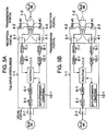
- the operation of the second full-duplex 3-portal bridge 1-2 is similar to a reception operation of the first full-duplex 3-portal bridge 1-1, which is described in the following with reference to Fig. 5B.
- a packet is transmitted from the bus #D to the reception portal 3-1 of the first dull-duplex 3-portal bridge 1-1. This packet is input to the routing unit 11-1 via the physical layer processing unit 7-1 and the link layer processing unit 8-1.
- the routing unit 11-1 discards the packet, whereas if the destination of the packet is the bus #A, the routing unit 11-1 identifies the type of the packet. If it is judged that the packet is an asynchronous stream packet converted from an original asynchronous packet, this packet is converted into an asynchronous packet by the asynchronous-stream-packet/asynchronous-packet converting unit 12-1. This converted asynchronous packet is transmitted to the bus #A via the link layer processing unit 6-1, the physical layer processing unit 5-1 and the usual portal 2-1.
- this packet is directly transmitted to the bus #A via the link layer processing unit 6-1, the physical layer processing unit 5-1 and the usual portal 2-1.
- Figs. 6A-6D are diagrams illustrating the comparison between a network system using a usual bridge and the network system shown in Figs. 4A and 4B.
- Fig. 6A shows the structure of the network system using the usual bridge
- Fig. 6B illustrates the operation of the network system while an asynchronous packet is transmitted.
- Fig. 6C shows the structure of the network system shown in Figs. 4A and 4B
- Fig. 6D illustrates the operation of the network system while an asynchronous packet is transmitted.
- an asynchronous packet is to be transmitted from the bus #A to the bus #B, it is transmitted from the bus #A to a usual bridge BR#1.
- the usual bridge BR#1 returns an acknowledge packet (Ack_pending) to the bus #A, it transmits the asynchronous packet to a usual bridge BR#2.
- the usual bridge BR#2 returns an acknowledge packet (Ack_pending) to the usual bridge BR#1, it transmits the asynchronous packet to the bus #B.
- the bus #B receives the asynchronous packet, it returns an acknowledge packet (Ack_complete) to the usual bridge BR#2.
- an asynchronous stream packet is transmitted between the full-duplex 3-portal bridges 1-1 and 1-2.
- the full-duplex 3-portal bridges 1-1 and 1-2 convert a packet, they do not return the acknowledge packet (Ack_pending), so that this network system has the transmission efficiency higher than that of the network system using the usual bridge.
- the network system of this embodiment can perform the full-duplex communication whose transmission efficiency is not lowered.
- the bus can be made to have a long distance without lowering the transmission efficiency.
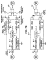
- Figs. 7A and 7B are diagrams illustrating the operation of the network system shown in Figs. 5A and 5B to be executed when a failure occurs in the network system.
- Fig. 7A illustrates the state of the network system immediately before the failure occurs
- Fig. 7B illustrates the state of the network system after the failure is coped with.
- the bridges 1-1 and 1-2 change the transmission portal 4-1 and the reception portal 3-2 to the usual portals. As a result, it becomes possible to perform the half-duplex two-way transmission between these portals, as shown in Fig. 7B.
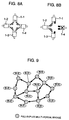
- Figs. 8A and 8B are diagrams showing another structure of the network system having the full-duplex 3-portal bridge shown in Fig. 3.
- This network system is a loop type network system configured by four full-duplex 3-portal bridges 1-1, 1-2, 1-3 and 1-4. It is assumed that in the state that the loop is formed as shown in Fig. 8A, a failure occurs in one full-duplex 3-portal bridge 1-4 to cut the loop.
- the transmission and reception portals of the other three full-duplex 3-portal bridges 1-1, 1-2 and 1-3 become the usual portals, so that it is possible to perform the half-duplex two-way transmission among the three full-duplex 3-portal bridges 1-1, 1-2 and 1-3.
- the network system shown in Figs. 7A and 7B can deal with only the disconnection of the cable, this network system shown in Figs. 8A and 8B can advantageously deal with also the failure of the node.
- Figs. 8A and 8B although the loop is formed by four bridges, it may be formed three or more bridges. Further, a net type of network system as shown in Fig. 9 may be used.
- the failure is detected in the following manner.
- a node located near to a failed node detects the failure to notify it to other nodes.
- a connection confirmation packet is periodically circulated in the loop so that any failure can be detected if the packet is not circulated.
- the packet is sent in the one-way direction and a node received the packet returns a response, similar to the trace root. Thereby, it is possible to locate the failure site by checking where the response is not returned. As the failure site is located and it is confirmed that the loop is already out of function, this effect is declared on the original loop. Thereafter, the one-way transmission is not performed and the bus is used as a usual bus.
- a downstream direction is a direction of a packet flowing on the loop when the loop is completed, and the upstream direction is a direction opposite to the downstream direction.
- the transmission portal 4-1 of the first full-duplex 3-portal bridge 1-1 is connected to the reception portal 3-2 of the second full-duplex 3-portal bridge 1-2, and that the reception portal 3-1 of the first full-duplex 3-portal bridge 1-1 is connected to the transmission portal 4-4 of the fourth full-duplex 3-portal bridge 1-4.
- the transmission portal 4-1 of the first full-duplex 3-portal bridge 1-1 is connected via the cable to the reception portal 3-2 of the second full-duplex 3-portal bridge 1-2. Thereby, the bus reset is generated.
- the transmission portal 4-1 becomes the cycle master. The case that the transmission portal 4-1 cannot become the cycle master will be later described.
- the self-ID process is performed to establish a bus. This bus is called a bus #C.
- the transmission portal 4-1 and the reception portal 3-2 negotiate each other via the bus #C.
- the transmission portal 4-1 becomes a transmission portal and the reception portal 3-2 becomes a reception portal.
- the bus reset is generated so that the transmission portal 4-1 becomes the cycle master.
- the loop is established. It is herein assumed that the loop has not established yet (in this example, there is no connection between the reception portal 3-1 and the transmission portal 4-4). It is therefore confirmed that the loop has not established yet. The procedure of confirming whether or not the loop is established will be later described. After this confirmation, the bus between the transmission portal 4-1 and the reception portal 3-2 operates as the usual bus until the loop is established.
- the reception portal 3-1 of the first full-duplex 3-portal bridge 1-1 is connected via the cable to the transmission portal 4-4 of the fourth full-duplex 3-portal bridge 1-4.
- the bus rest is generated.
- the transmission portal 4-4 becomes the cycle master.
- the case that the transmission portal 4-4 cannot become the cycle master will be later described.
- the self-ID process is performed to establish a bus. This bus is called a bus #D.
- the transmission portal 4-4 and the reception portal 3-1 negotiate each other via the bus #D. It is confirmed that the transmission portal 4-4 becomes a transmission portal and the reception portal 3-1 becomes a reception portal, when a loop is established. In this case, it is not necessary to predetermine which one of the transmission portal 4-4 and the reception portal 3-1 becomes a transmission portal and the other becomes a reception portal. This may be determined dynamically during the negotiation by taking into consideration the relation between nodes on a bus constituting another portion of the loop.
- the bus reset is generated so that the transmission portal 4-4 becomes the cycle master. Next, it is confirmed whether or not the loop is established. The procedure of confirming whether or not the loop is established will be later described.
- the buses #C and #D are used as the one-way buses to form the loop.
- One method is to confirm the end of the loop. Since the node has the transmission and reception portals, it is possible to confirm that the node is an "end” if one or both of the transmission and reception portals are not connected. The instant when the loop is completed corresponds to the instant when the node which has been the "end” does not become the "end”. The node which recognizes that it is not the "end”, flows a loop detection packet in the downstream direction.
- a node received this packet flows the packet in the downstream direction if the node is not the "end". If the packet returns from the upstream node to the node first issued the packet, it can be recognized that the loop has been established.
- the node which is the "end” returns in the upstream direction a packet indicating that the loop has not established yet.
- this packet is received from the downstream node, it can be recognized that the loop has not established yet.
- One countermeasure is a method of utilizing a "loop ID" or specific information which can be substituted for the loop ID (such as a list of nodes in the loop), each loop. If the loop ID is added to the loop detection packet to explicitly indicate the loop to be detected, then each loop can be dealt with as if it is independent. With this countermeasure, however, it is necessary to frequently exchange information such as information about whether a subject node is contained in which loop, information about what loop is to be established, information about how respective loops are routed, and other information.
- a proper ID different from that of LO#A is added to the loop detection packet.
- the rules of adding the ID includes: preparing sufficiently large numbers; randomly selecting these numbers; preparing IDs distinguishing between established loops and still not established loops; and the like.
- a server for managing IDs of existing loops may be provided. It is herein assumed that the loop now under establishment is LO#B. The packet is then flowed to the downstream side. Upon reception of a packet for detecting the loop LO#B, a node which receives the packet flows it to all of the downstream sides.
- Each of nodes which are contained in the loop LO#A adds to the packet a mark indicating that the node is contained in the loop LO#A.
- each of nodes which are not contained in the loop LO#A adds to the packet a mark indicating that the packet has passed through the route which is not contained in the loop LO#A.
- Another countermeasure is a method which does not consider whether or not a node is contained in how many loops.
- the node recognizes only whether or not it is contained in at least one loop or whether or not it is contained in no loop.
- the loop detection packet is flowed to the downstream side. If the packet circulates around the loop and returns to the node, it can be recognized that the node belongs to some loop. In this case, it is not necessary to recognize a route through which the packet has passed.
- a packet is transmitted from the bus #A to the usual portal 2-1 of the first full-duplex 3-portal bridge 1-1. This packet is input to the routing unit 11-1 via the physical layer processing unit (PHY) 5-1 and the link layer processing unit (LINK) 6-1.
- PHY physical layer processing unit
- LINK link layer processing unit
- the routing unit 11-1 discards the packet, whereas if the destination of the packet is either of the buses #B1 to #B3, the routing unit 11-1 identifies the type of the packet. If it is judged that the packet is an asynchronous packet, this packet is converted into an asynchronous stream packet by the asynchronous-stream-packet/asynchronous-packet converting unit 12-1. This converted asynchronous stream packet is transmitted to the bus #C via the link layer processing unit (LINK) 10-1, the physical layer processing unit (PHY) 9-1 and the transmission portal 4-1.
- LINK link layer processing unit
- PHY physical layer processing unit
- the routing unit 11-1 judges that the packet is an isochronous packet or an asynchronous stream packet, this packet is directly transmitted to the bus #C via the link layer processing unit (LINK) 10-1, the physical layer processing unit (PHY) 9-1 and the transmission portal 4-1.
- LINK link layer processing unit
- PHY physical layer processing unit
- the transmission portal 4-1 instead of determining whether or not the packet is discarded by judging whether or not the destination of the packet is either of the buses #B1 to #B3, it may be determined whether or not the packet is discarded by judging whether or not the destination of the packet is the bus #A.
- the packet transmitted to the bus #C is input from the reception portal 3-2 of the second full-duplex 3-portal bridge 1-2 to the inside of the bridge 1-2.
- the operation of the second full-duplex 3-portal bridge 1-2 is similar to the reception operation of the first full-duplex 3-portal bridge 1-1, which is described in the following with reference to Fig. 10B.
- a packet is transmitted from the bus #D to the reception portal 3-1 of the first full-duplex 3-portal bridge 1-1. This packet is input to the routing unit 11-1 via the physical layer processing unit (PHY) 7-1 and the link layer processing unit (LINK) 8-1.
- PHY physical layer processing unit
- LINK link layer processing unit
- the routing unit 11-1 identifies the type of the packet. If it is judged that the packet is an asynchronous stream packet converted from an original asynchronous packet, this packet is converted into an asynchronous packet by the asynchronous-stream-packet/asynchronous-packet converting unit 12-1. This converted asynchronous packet is transmitted to the bus #A via the link layer processing unit (LINK) 6-1, the physical layer processing unit (PHY) 5-1 and the usual portal 2-1. On the other hand, if the routing unit 11-1 judges that the packet is an isochronous packet or an original asynchronous stream packet, this packet is directly transmitted to the bus #A via the link layer processing unit 6-1, the physical layer processing unit 5-1 and the usual portal 2-1. If the destination of the packet is the bus #C, this packet is sent to the bus #C.
- LINK link layer processing unit
- PHY physical layer processing unit
- the second embodiment of the present invention has the following technical features (1) to (5).
- the third embodiment of the present invention relates to a one-way bridge having one usual portal and one transmission or reception portal, and to a network system using such bridge.
- Figs. 11A and 11B are block diagrams showing the structure of the one-way bridge as the network bus bridge according to the third embodiment of the present invention.
- Fig. 11A shows a one-way transmission bridge
- Fig. 11B shows a one-way reception bridge.
- a one-way transmission bridge 21 has a usual portal 22 and a transmission portal 23 each of which is connected to the IEEE1394 bus.
- the usual portal 22 and the transmission portal 23 are connected to physical layer processing units (PHY) 24 and 26, respectively.
- the physical layer processing units (PHY) 24 and 26 are connected to link layer processing units (LINK) 25 and 27, respectively.
- An address filtering unit 28 and an asynchronous-stream-packet/asynchronous-packet converting unit (Asyn-Stream/Asyn converting unit) 29 are connected between the link layer processing units 25 and 27.
- a one-way reception bridge 31 has a usual portal 32 and a reception portal 33 each of which is connected to the IEEE1394 bus.
- the usual portal 32 and the reception portal 33 are connected to physical layer processing units (PHY) 34 and 36, respectively.
- the physical layer processing units (PHY) 34 and 36 are connected to link layer processing units (LINK) 35 and 37, respectively.
- An address filtering unit 38 and an asynchronous-stream-packet/asynchronous-packet converting unit (Asyn-Stream/Asyn converting unit) 39 are connected between the link layer processing units 35 and 37.
- the address filtering units 28 and 38 execute the routing of a received packet, similar to the routing unit 11 of the second embodiment.
- the other constituents have the similar functions to those of the constituents represented by identical reference numerals of the second embodiment.
- each of the bridges shown in Figs. 11A and 11B has one usual portal and one transmission or reception portal
- the present invention is not limited to this configuration.
- a relay node having one transmission portal and one reception portal may be used, or a node having one transmission portal and a plurality of usual portals between which the node operates as a usual bridge may be used.
- an isochronous-packet/asynchronous-packet converting unit for converting between an isochronous packet and an asynchronous packet may be provided. Also, only those blocks pertaining to the network connection are shown in Figs. 11A and 11B.
- a recorder/player, a television tuner, a display or another apparatus all of which are for isochronous data is provided, for example, it is possible to realize a DVD recorder/player, a set-top box or a television receiver all of which are provided with a bridge function.
- Figs. 12A and 12B are diagrams showing a network system using the one-way bridge shown in Figs. 11A and 11B.
- the network system shown in Fig. 12A can execute the broadcasting, and the network system shown in Fig. 12B can execute the two-way transmission.
- the network system shown in Fig. 12A has one one-way transmission bridge 21-1, four one-way reception bridges 31-1 to 31-4, one broadcasting bus, and five buses #1 to #5.
- a usual portal of the one-way transmission bridge 21-1 is connected to the bus #1, and the transmission portal thereof is connected to the broadcasting bus.
- the reception portals of the one-way reception bridges 31-1 to 31-4 are connected to the broadcasting bus, and the usual portals thereof are connected to the buses #2 to #5, respectively.
- Each transmission portal continues to be the cycle maser and the BOSS. Generally, the reception portal does not become the BOSS.
- a packet input from the bus #1 to the one-way transmission bridge 2-1 is input to each of the one-way reception bridges 31-1 to 31-4 via the broadcasting bus, and then is input to the buses #2 to #5 via the one-way reception bridges 31-1 to 31-4.
- This network system can therefore realize the broadcasting communication without the loss of the transmission efficiency. Further, it is possible to realize the long distance transmission without lowering the transmission efficiency.
- the network system shown in Fig. 12B has two one-way transmission bridges 21-1 and 21-2, two one-way reception bridges 31-1 and 31-2, and two buses #1 and #2.
- Usual portals of the one-way transmission bridges 21-1 and 21-2 are connected to the buses #1 and #2, respectively.
- Usual portals of the one-way reception bridges 31-1 and 31-2 are connected to the buses #2 and #1, respectively.
- Transmission portals of the one-way transmission bridges 21-1 and 21-2 are connected to reception portals of the one-way reception bridges 31-1 and 31-2, respectively.
- Each transmission portal continues to be the cycle maser and the BOSS. Generally, the reception portal does not become the BOSS.
- a packet transmitted from the bus #1 is input to the bus #2 via the one-way transmission bridge 21-1 and the one-way reception bridge 31-1.
- a packet transmitted from the bus #2 is input to the bus #1 via the one-way transmission bridge 21-2 and the one-way reception bridge 31-2.
- the half-duplex two-way transmission can be performed by changing the transmission and reception portals to the usual transmission/reception portals to form the usual bridges.
- the third embodiment of the present invention has the following technical features (1) to (4).
- the present invention is applicable not only to the network system using the IEEE1394 bus but also to other network systems using half-duplex type buses.
- the one-way transmission is executed from the transmission node or transmission portal to the reception node or reception portal. It is therefore possible to provide a network system with excellent effects capable of avoiding the bus bandwidth use efficiency from being lowered by the transmission delay to thereby improve the transmission efficiency.
- the network bus bridge of the present invention it is possible to provide a network bus bridge with excellent effects capable of executing the one-way transmission to and from a half-duplex bus to thereby improve the transmission efficiency.
- the one-way transmission from a transmission portal to a reception portal can improve the transmission efficiency.
- a pair of one-way transmissions in the reverse direction it becomes possible to provide a network system with excellent effects capable of realizing the two-way transmission with the high transmission efficiency.
- the network system of the present invention it is possible to provide a network system with excellent effects capable of improving the transmission efficiency and realizing a loop type transmission by incorporating the one-way transmission from a transmission portal to a reception portal.
Abstract
Description
- The present invention relates to a network bus bridge and a network system using the network bus bridge, and more particularly to a network bus bridge and a network system which are capable of preventing the bus bandwidth use efficiency from being lowered by the transmission delay.
- A network having the IEEE1394 high-speed serial bus (hereinafter simply called the "IEEE1394 bus") has been paid attention as one of the bus type networks. The IEEE1394 bus has a number of characteristic features such as automatic setting of node IDs, hot plug and play, and isochronous mode suitable for transmission of moving-image data, and has been adopted as a bus for transmitting digital image data.
- For the usual arbitration used in IEEE1394-1995, a root node issues a transmission permission. In P1394b, the transmission order of nodes is determined by a procedure called the "BOSS arbitration". For the BOSS arbitration, a node called "BOSS" issues the transmission permission. After the node issues the transmission permission, this node is not the BOSS any more, but the node received the transmission permission becomes a new BOSS.
- In other words, the BOSS arbitration is one kind of token passing. Not becoming the BOSS by giving the transmission permission to another node corresponds to "tossing a token", and becoming the BOSS by receiving the transmission permission corresponds to "receiving a token".
- A different point of the BOSS arbitration from the general token passing is that in the token passing the circulation order of the token is predetermined, whereas in the BOSS arbitration the node becoming the BOSS (receiving a token) is determined each time through competition. Namely, in the BOSS arbitration, a node which does not desire to transmit data does not become the BOSS (i.e., does not receive a token).
- Generally, a half-duplex bus type network has advantages that broadcast is easy and the network topology is flexible, but has disadvantages that other nodes cannot transmit data while one node transmits a frame of a packet. The period while a node transmits a frame is more precisely "a period from when a frame starts being transmitted to when it becomes that the next frame can be transmitted". This period can be generally defined as a period from the time instance when a node starts transmitting a frame to when the transmitted frame extinguishes from a bus. Namely, when the bus is broadened (i.e., the maximum value of a delay between nodes is set large) for long distance transmission, the transmission delay time becomes long. As a result, the "period from when a frame starts being transmitted to when it becomes that the next frame can be transmitted" is prolonged by the transmission delay. This is apparent from the following equation [1] which indicates the time for the same size frame to be transmitted to the whole bus:
- It can be understood that when the transmission delay occurs, an additional time equal to the transmission delay requires transmitting the same size frame, so that the occurrence of the transmission delay lowers the bandwidth efficiency. This problem is troublesome in that the higher the transmission rate is, the larger the influence of the transmission delay is, as seen from the equation [1].
- In order to cope with this lower efficiency, a large frame is generally used. Because the influence of the transmission delay can be mitigated as the frame size becomes large, as apparent from the equation [1]. The large frame can therefore suppress the transmission efficiency from being lowered.
- A network using the IEEE1394 bus is one of the half-duplex bus type networks. This network therefore has the characteristics that if the transmission distance is elongated to generate the transmission delay, the bandwidth efficiency lowers.
- In the BOSS arbitration of P1394b, the BOSS can transmit a frame. After the BOSS transmits the transmission permission to another node after transmitting the frame, it is not a BOSS any more. The node received the transmission permission becomes a new BOSS and can transmit a frame immediately thereafter. Namely, in P1394b, a period while a frame cannot be transmitted is a period from the time instant when the BOSS transmits the transmission permission to the time instant when another node receives the transmission permission and becomes the new BOSS. During this period, there is no BOSS on the bus. Therefore, any frame will not be transmitted. This will be described in more detail with reference to Figs. 13 and 14.
- Fig. 13 is a diagram showing an example of a network system using the IEEE1394 bus, and Fig. 14 is a diagram showing an example of the operation timing of the network system. In the network system shown in Fig. 13, four nodes "A", "B", "C" and "D" are connected to the IEEE1394 bus. The node "B" is a cycle master. In Fig. 14, a both-head arrow in the uppermost area indicates a transmission cycle of 125µs. During the time duration "B", "C", "D", "A", "D", "B", "C" and "A" indicated by both-head arrows in the second uppermost area, nodes corresponding to these alphabets become the BOSS. Namely, they become the BOSS in the order of node "B" → node "C" → node "D" → node "A" → node "D" → node "B" → node "C" → node "A". Idle periods caused by the transmission delay are indicated by both-head arrows (in the third uppermost area) during the period when each of the nodes becomes the BOSS. The transmission timings of nodes "A", "B", "C" and "D" are indicated by "A", "B", "C" and "D" affixed to the leftmost area in Fig. 14.
- The operation of the network system shown in Fig. 13 will be described. After the node "B" which is the cycle master and the BOSS transmits a cycle start packet CS on the bus, it transmits a transmission permission token on the bus. The cycle start packet CS and the transmission permission token are flowing on the bus and are received by the nodes "A", "C" and "D". The node "C" receives the transmission permission token to become the BOSS. Thereafter, the node "C" transmits an isochronous packet IsC and the transmission permission token on the bus. Similarly, the nodes "D" and "A" become thereafter the BOSS in this order. The node "D" transmits an isochronous packet IsD and the transmission permission token on the bus, and the node "A" transmits an isochronous packet IsA and the transmission permission token on the bus. After the nodes "B", "C", "D" and "A" sequentially transmit isochronous packets on the bus in the above manner, the nodes "D" and "C" sequentially transmit asynchronous packets AD and AC. In transmitting the asynchronous packet, it is determined that the node which receives the asynchronous packet returns an acknowledgement packet to the transmitting node. Therefore, for the asynchronous packet AD, the node "B" becomes the BOSS and returns the acknowledge packet to the node "D", and for the asynchronous packet AC, the node "A" becomes the BOSS and returns the acknowledge packet to the node "D".
- It can be understood from the above explanation that the idle time period is a period while the BOSS does not exist. In the case of the token passing, the idle period is a period while a token flows on the network. Therefore, the above-described general formula [1] becomes the following formula [2] for the BOSS arbitration:
- In the case of the IEEE1394 bus, a long distance such as a large bus size will not cause any deterioration of the efficiency due to the long distance transmission delay if the nodes which become the BOSS (which desire to transmit) are concentrated in a narrow area. The reason is as follows. The idle time is a time for which the transmission permission token is transferred from the current BOSS to the next BOSS. Therefore, only the transmission delay between the nodes which become the BOSS (which desire to transmit) becomes an issue, and the bus size is not directly related to the efficiency. Namely, the following inequality [3] is established:
- However, it is generally rare that the nodes which become the BOSS (which desire to transmit) are concentrated in a narrow area of a broad bus. It is usual to consider that the nodes exist in an area from one end to the other end of the bus. The influence of the bus size is therefore hard to be reduced, so that it is not substantial that the value of equation [2] is much smaller than that of equation [1]. It can be said that the BOSS arbitration is much more efficient than the general token passing.
- One approach to solving this problem of the low efficiency is to make large the frame size similar to the general network system. The larger the frame size is, the less the influence of the transfer time of the transmission permission token is.
- However, the IEEE1394 bus is associated with a critical problem. As shown in Fig. 14, the IEEE1394 bus has the cycle of 125 µsec. Data transfer is executed by the repetitive transmission of a small frame in each cycle in order to suppress the generation of the jitter. For example, if data is to be transmitted at the bandwidth of 6 Mbps, it is necessary to transmit a frame having at least a size of 6 Mbps×125 µs = 750 bits = 94 bytes (4 bytes + header size) in one cycle. This cycle poses the following limit of the IEEE1394 bus expressed by the following inequality:
- A more specific representation of inequality [4] becomes the following equation:
- Namely, if the frame size is to be made large, it is necessary not only to satisfy the limit of a frame size defined by the specification but also to satisfy the condition defined by inequality [5]. It means that as the number of frames to be transmitted in one cycle increases too large, the frame size cannot be made large. Since the IEEE1394 bus has this problem of an inability to make the frame size large, another solution method is required.
- The present invention has been made in order to solve the above problems. An object of the present invention is to provide a network bus bridge and a network system which are capable of preventing the bus bandwidth use efficiency from being lowered by the transmission delay in the half-duplex bus type network system such as the IEEE1394 bus.
- The first network system of the present invention comprises: one transmission node; one or more reception nodes; and a half-duplex bus connected between the transmission node and the reception nodes. With this configuration, the one-way transmission is performed from the transmission node to the reception node, so that the bus bandwidth use efficiency can be prevented from being lowered by the transmission delay and the transmission efficiency can be improved.
- The first network bus bridge of the present invention comprises one or more transmission portals. With this configuration, the one-way transmission from the transmission portal to a half-duplex bus becomes possible.
- The second network bus bridge of the present invention comprises one or more reception portals. With this configuration, the one-way transmission from a half-duplex bus to the reception portal becomes possible.
- The second network system of the present invention comprises: a first network bus bridge having one transmission portal and one transmission/reception portal; a plurality of second network bus bridges each having one reception portal and one transmission/reception portal; and a half-duplex bus connected between the transmission portal and the reception portal. With this configuration, by realizing the one-way transmission between the transmission portal of the first network bus bridge and the reception portal of the second network bus bridge, the transmission efficiency can be improved.
- The third network system of the present invention comprises:
- a first network bus bridge having one transmission portal and one transmission/reception portal;
- a second network bus bridge having one reception portal and one transmission/reception portal;
- a third network bus bridge having one transmission portal and one transmission/reception portal; and
- a fourth network bus bridge having one reception portal and one transmission/reception portal, wherein
- the transmission portal of the first network bus bridge and the reception portal of the second network bus bridge is connected via a half-duplex bus;
- the transmission portal of the third network bus bridge and the reception portal of the fourth network bus bridge is connected via a half-duplex bus;
- the transmission/reception portal of the first network bus bridge and the transmission/reception portal of the fourth network bus bridge is connected via a half-duplex bus; and
- the transmission/reception portal of the second network bus bridge and the transmission/reception portal of the third network bus bridge is connected via a half-duplex bus.
-
- With this configuration, by realizing the one-way transmission from the transmission portal to the reception portal, the transmission efficiency can be improved. Also, by providing a pair of the one-way transmissions in the reverse direction, the two-way transmission with the high transmission efficiency can be realized.
- The third network bus bridge of the present invention comprises: one or more transmission portals; and one or more reception portals. With this configuration, the one-way transmission from the transmission portal to a half-duplex bus and the one-way transmission from the reception portal to the half-duplex bus become possible.
- The fourth network system of the present invention comprises two third network bus bridges, wherein the transmission and reception portals of one of the two third network bus bridges are connected to the reception and transmission portals of the other via half-duplex buses, respectively; and the transmission/reception portals of the two third network bus bridges are connected via a half-duplex bus. With this configuration, by realizing the one-way transmission from the transmission portal to the reception portal, the transmission efficiency can be improved. Also, by providing a pair of the one-way transmissions in the reverse direction, the two-way transmission with the high transmission efficiency can be realized.
- The fourth network system of the present invention comprises three or more third network bus bridges, wherein the connections of the transmission and reception portals of one of two adjacent network bus bridges to the reception and transmission portals of the other of the two adjacent network bus bridges via half-duplex buses are repeated to form a loop along which data flows in one direction. With this configuration, by realizing the one-way transmission from the transmission portal to the reception portal, the transmission efficiency can be improved and the loop type transmission can be realized.
-
- Fig. 1 is a schematic diagram showing a network system according to a first embodiment of the present invention;
- Fig. 2 is a diagram showing an example of the transmission timings of the network system shown in Fig. 1;
- Fig. 3 is a block diagram showing the structure of a full-duplex 3-portal bridge as a network bus bridge according to a second embodiment of the present invention;
- Figs. 4A and 4B are diagrams showing the structure of a network system having the full-duplex 3-portal bridge shown in Fig. 3;
- Figs. 5A and 5B are block diagrams illustrating the operation of the network system shown in Figs. 4A and 4B;
- Figs. 6A-6D are diagrams illustrating the comparison between a network system using a usual bridge and the network system shown in Figs. 4A and 4B;
- Figs. 7A and 7B are diagrams illustrating the operation to be executed when a failure occurs in the network system shown in Figs. 5A and 5B;
- Figs. 8A and 8B are diagrams showing another structure of the network system having the full-duplex 3-portal bridge shown in Fig. 3;
- Fig. 9 is a diagram showing still another structure of the network system having the full-duplex 3-portal bridge shown in Fig. 3;
- Figs. 10A and 10B are block diagrams illustrating the operation of the network system shown in Figs. 8A and 8B;
- Figs. 11A and 11B are block diagrams showing the structure of a one-way bridge as a network bus bridge according to a third embodiment of the present invention;
- Figs. 12A and 12B are diagrams showing a network system having the one-way bridge shown in Figs. 11A and 11B;
- Fig. 13 is a diagram showing an example of a conventional network system; and
- Fig. 14 is a diagram showing an example of transmission timings of the conventional network system.
-
- Embodiments of the present invention will be described in detail with reference to Figs. 1-12B.
- In the first embodiment of the present invention, one transmission node and one reception node are connected together by the IEEE1394 bus, and only the one-way transmission from the transmission node to the reception node is performed to improve the transmission efficiency.
- Fig. 1 is a diagram showing a network system according to the first embodiment of the present invention, and Fig. 2 is a diagram showing an example of the transmission timings of the network system. In the network system shown in Fig. 1, two nodes "A" and "B" are connected via the IEEE1394 bus. The node "A" is always a cycle master and the BOSS. The node "B" operates only as a reception node. Packets to be transmitted are an isochronous packet and an asynchronous stream packet both of which are not required to return an acknowledgement. An asynchronous packet which is required to return the acknowledgement is not transmitted. An apparatus to be used as a node is, for example, a DVD recorder/player, a digital video tape recorder, a set-top box, an MD recorder/player, a television receiver, a personal computer or the like.
- As shown in Fig. 2, in the network system configured as above, after the node "A" transmits a cycle start packet CS, it sequentially transmits five isochronous packets IsA on the bus, and thereafter sequentially transmits two asynchronous stream packets AssA on the bus. Each packet transmitted on the bus is received by the node "B" after a lapse of a transmission delay time. In practice, since there is an inter-frame gap between packets, it is not possible to have the transmission efficiency of 100 %. However, if a process at a node does not become a bottle neck, the transmission efficiency can be raised to the theoretical maximum efficiency.
- As above, in the network system according to the first embodiment of the present invention, since the node "B" does not perform a transmission operation, it is not necessary to transmit a transmission permission token from the node "A", which is the cycle master and the BOSS, to the node "B". There is therefore no idle time shown in Fig. 14, so that it is possible to prevent the transmission efficiency from being lowered.
- In the embodiment shown in Fig. 1, although one reception node is used, a plurality of reception nodes may be connected to the transmission node "A".
- The second embodiment of the present invention relates to a full-duplex multi-portal bridge having one usual portal, one or more transmission portals and one or more reception portals, and to a network system using such a bridge.
- Fig. 3 is a block diagram showing the structure of a full-duplex 3-portal bridge used as a network bus bridge according to the second embodiment of the present invention.
- As shown in Fig. 3, the full-duplex 3-
portal bridge 1 has ausual portal 2, areception portal 3 and atransmission portal 4 each of which is connected to the IEEE1394 bus. Theusual portal 2, thereception portal 3 and thetransmission portal 4 are connected to physical layer processing units (PHYs) 5, 7 and 9, respectively. The physicallayer processing units Aa routing unit 11 and an asynchronous-stream-packet/asynchronous-packet converting unit (Assn-Stream/Assn converting unit) 12 are connected among the linklayer processing units - The
usual portal 2 can perform the transmission/reception operations, thereception portal 3 can perform only the reception operation, and thetransmission portal 4 can perform only the transmission operation. Theusual portal 2 is connected to the bus, thereception portal 3 is connected to a downstream line, and thetransmission portal 4 is connected to an upstream line. The physicallayer processing units layer processing units routing unit 11 executes a routing process for a received packet. If a packet received via theusual portal 2 is an asynchronous packet, the asynchronous-stream-packet/asynchronous-packet converting unit 12 converts it into an asynchronous stream packet. If a packet received via theusual portal 2 is an asynchronous stream packet converted from an original asynchronous packet, the convertingunit 12 converts it into the asynchronous packet. Thereception portal 3 and thetransmission portal 4 can operate as a usual portal when a failure occurs in the network system. Broken lines in Fig. 3 indicate a data flow during the system failure. - The bridge shown in Fig. 3 includes one transmission portal and one reception portal. However, if the condition that the total throughput of the transmission portals is equal to that of the reception portals is satisfied, the number of the transmission portals and the number of the reception portals are not required to be equal. Further, for example, a relay node including one transmission portal and one reception portal may be used, or a node which includes one transmission portal and a plurality of usual portals and operates as a usual bridge between the usual portals may be used. Further, an isochronous-packet/asynchronous-packet converting unit (Iso/Asyn converting unit) which executes a conversion between an isochronous packet and an asynchronous packet may be provided. Furthermore, only the blocks pertaining to the connection between the networks are shown in Fig. 3. However, for example, a recorder/player, a television tuner, a display, or another apparatus, respectively for isochronous data (Iso data), may be used to realize a DVD recorder/player, a set-top box, or a television receiver, respectively provided with a bridge function.
- Figs. 4A and 4B are diagrams showing an example of a network system having the full-duplex 3-portal bridge shown in Fig. 3. Fig. 4A illustrates a connection relation and a data flow, and Fig. 4B shows a bus formed between two bridges.
- This network system has a first full-duplex 3-portal bridge 1-1, a second full-duplex 3-portal bridge 1-2, a bus #A, and a bus #B. A usual portal of the first full-duplex 3-portal bridge 1-1 is connected to the bus #A, and a usual portal of the second full-duplex 3-portal bridge 1-2 is connected to the bus #B. Transmission and reception portals of the first full-duplex 3-portal bridge 1-1 are connected to reception and transmission portals of the second full-duplex 3-portal bridge 1-2, respectively. A bus #C is provided between the transmission portal of the first full-duplex 3-portal bridge 1-1 and the reception portal of the second full-duplex 3-portal bridge 1-2. A bus #D is provided between the transmission portal of the second full-duplex 3-portal bridge 1-2 and the reception portal of the first full-duplex 3-portal bridge 1-1. The transmission portal continues to be the cycle maser and the BOSS. Generally, the reception portal does not become the BOSS.
- In the network system configured as above, the two-way transmission of the isochronous packets, asynchronous packets and asynchronous stream packets is performed between the bus #A and the usual portal of the first full-duplex 3-portal bridge 1-1. Similarly, the two-way transmission of the isochronous packets, asynchronous packets and asynchronous stream packets is performed between the bus #B and the usual portal of the second full-duplex 3-portal bridge 1-2. Further, the one-way transmission of the isochronous packets and asynchronous stream packets is performed between the transmission portal of the first full-duplex 3-portal bridge 1-1 and the reception portal of the second full-duplex 3-portal bridge 1-2. Similarly, the one-way transmission of the isochronous packets and asynchronous stream packets is performed between the transmission portal of the second full-duplex 3-portal bridge 1-2 and the reception portal of the first full-duplex 3-portal bridge 1-1. The first and second full-duplex 3-portal bridges 1-1 and 1-2 execute the conversion between the asynchronous stream packet and the asynchronous packet if necessary.
- Next, the operation of the network system shown in Figs. 4A and 4B will be described with reference to Figs. 5A and 5B.
- First, the initial operation of the network system shown in Figs. 5A and 5B will be described.
- The transmission portal 4-1 of the first full-duplex 3-portal bridge 1-1 and the reception portal 3-2 of the second full-duplex 3-portal bridge 1-2 are first connected via a cable. Thereby, a bus reset is generated. In a tree-ID process, the transmission portal 4-1 becomes the cycle master. The case that the transmission portal 4-1 cannot become the cycle master will be later described. A self-ID process is performed to establish a bus. This bus is called a bus #C.
- The transmission portal 4-1 and the reception portal 3-2 negotiate each other via the bus #C to confirm the following two facts. When a full-duplex communication becomes possible, the transmission portal 4-1 becomes a transmission portal and the reception portal 3-2 becomes a reception portal. Since the reception portal 3-1 and the transmission portal 4-2 have not connected yet, the full-duplex communication has still not been possible.
- In this case, it is not necessary to predetermine which one of the transmission portal 4-1 and the reception portal 3-2 becomes a transmission portal and the other becomes a reception portal. This may be determined dynamically during the negotiation. If the transmission portal 4-1 has not become the cycle master, the bus reset is generated so that the transmission portal 4-1 becomes the cycle master. After the above-described confirmation, the connection between the transmission portal 4-1 and the reception portal 3-2 functions as a usual half-duplex bus until the transmission portal 4-2 and the reception portal 3-1 are connected.
- Next, the transmission portal 4-2 and the reception portal 3-1 are connected via a cable. Thereby, the bus reset is generated. In the tree-ID process, the transmission portal 4-2 becomes the cycle master. The case that the transmission portal 4-2 cannot become the cycle master will be later described. The self-ID process is performed to establish a bus. This bus is called a bus #D.
- The transmission portal 4-2 and the reception portal 3-1 negotiate each other via the bus #D to confirm the following facts. When a full-duplex communication becomes possible, the transmission portal 4-2 becomes a transmission portal and the reception portal 3-1 becomes a reception portal. Since the transmission portal 4-1 and the reception portal 3-2 have already been connected and the negotiation has been completed, the full-duplex communication is possible.
- In this case, it is not necessary to predetermine which one of the transmission portal 4-2 and the reception portal 3-1 becomes a transmission portal and the other becomes a reception portal. This may be determined dynamically during the negotiation by taking into consideration the relation between the transmission portal 4-1 and the reception portal 3-2. If the transmission portal 4-2 has not become the cycle master, the bus reset is generated so that the transmission portal 4-2 becomes the cycle master. Thereafter, confirmation is made to start the full-duplex communication by using the buses #C and #D as the one-way buses.
- Next, the transmission operation will be described with reference to Fig. 5A.
- A packet is transmitted from the bus #A to the usual portal 2-1 of the first dull-duplex 3-portal bridge 1-1. This packet is input to the routing unit 11-1 via the physical layer processing unit (PHY) 5-1 and the link layer processing unit (LINK) 6-1.
- If the destination of the packet is not the bus #B, the routing unit 11-1 discards the packet, whereas if the destination of the packet is the bus #B, the routing unit 11-1 identifies the type of the packet. If it is judged that the packet is an asynchronous packet, this packet is converted into an asynchronous stream packet by the asynchronous-stream-packet/asynchronous-packet converting unit (Asyn-Stream/Asyn converting unit) 12-1. This converted asynchronous stream packet is transmitted to the bus #C via the link layer processing unit (LINK) 10-1, the physical layer processing unit (PHY) 9-1 and the transmission portal 4-1. On the other hand, if the routing unit 11-1 judges that the packet is an isochronous packet or an asynchronous stream packet, this packet is directly transmitted to the bus #C via the link layer processing unit 10-1, the physical layer processing unit 9-1 and the transmission portal 4-1.
- The packet transmitted to the bus #C is input from the reception portal 3-2 of the second full-duplex 3-portal bridge 1-2 to the inside of this bridge, and then is transmitted from the usual portal thereof to the bus #B. In this case, the operation of the second full-duplex 3-portal bridge 1-2 is similar to a reception operation of the first full-duplex 3-portal bridge 1-1, which is described in the following with reference to Fig. 5B.
- The reception operation will be described with reference to Fig. 5B. A packet is transmitted from the bus #D to the reception portal 3-1 of the first dull-duplex 3-portal bridge 1-1. This packet is input to the routing unit 11-1 via the physical layer processing unit 7-1 and the link layer processing unit 8-1.
- If the destination of the packet is not the bus #A, the routing unit 11-1 discards the packet, whereas if the destination of the packet is the bus #A, the routing unit 11-1 identifies the type of the packet. If it is judged that the packet is an asynchronous stream packet converted from an original asynchronous packet, this packet is converted into an asynchronous packet by the asynchronous-stream-packet/asynchronous-packet converting unit 12-1. This converted asynchronous packet is transmitted to the bus #A via the link layer processing unit 6-1, the physical layer processing unit 5-1 and the usual portal 2-1. On the other hand, if the routing unit 11-1 judges that the packet is an isochronous packet or an original asynchronous stream packet, this packet is directly transmitted to the bus #A via the link layer processing unit 6-1, the physical layer processing unit 5-1 and the usual portal 2-1.
- Figs. 6A-6D are diagrams illustrating the comparison between a network system using a usual bridge and the network system shown in Figs. 4A and 4B. Fig. 6A shows the structure of the network system using the usual bridge, and Fig. 6B illustrates the operation of the network system while an asynchronous packet is transmitted. Fig. 6C shows the structure of the network system shown in Figs. 4A and 4B, and Fig. 6D illustrates the operation of the network system while an asynchronous packet is transmitted.
- As shown in Figs. 6A and 6B, if an asynchronous packet is to be transmitted from the bus #A to the bus #B, it is transmitted from the bus #A to a usual
bridge BR# 1. After the usualbridge BR# 1 returns an acknowledge packet (Ack_pending) to the bus #A, it transmits the asynchronous packet to a usualbridge BR# 2. After the usualbridge BR# 2 returns an acknowledge packet (Ack_pending) to the usualbridge BR# 1, it transmits the asynchronous packet to the bus #B. After the bus #B receives the asynchronous packet, it returns an acknowledge packet (Ack_complete) to the usualbridge BR# 2. - In this embodiment shown in Figs. 6C and 6D, an asynchronous stream packet is transmitted between the full-duplex 3-portal bridges 1-1 and 1-2. Although the full-duplex 3-portal bridges 1-1 and 1-2 convert a packet, they do not return the acknowledge packet (Ack_pending), so that this network system has the transmission efficiency higher than that of the network system using the usual bridge. The network system of this embodiment can perform the full-duplex communication whose transmission efficiency is not lowered. The bus can be made to have a long distance without lowering the transmission efficiency.
- Figs. 7A and 7B are diagrams illustrating the operation of the network system shown in Figs. 5A and 5B to be executed when a failure occurs in the network system. Fig. 7A illustrates the state of the network system immediately before the failure occurs, and Fig. 7B illustrates the state of the network system after the failure is coped with.
- As shown in Fig. 7A, in the state that the one-way transmission is possible between the transmission portal 4-1 of the first full-duplex 3-portal bridge 1-1 and the reception portal 3-2 of the second full-duplex 3-portal bridge 1-2 and that the one-way transmission is possible between the transmission portal 4-2 of the second full-duplex 3-portal bridge 1-2 and the reception portal 3-1 of the first full-duplex 3-portal bridge 1-1, it is assumed that the cable between the transmission portal 4-2 and the reception portal 3-1 is disconnected and data cannot be transmitted therebetween.
- In this case, when the first and second full-duplex 3-portal bridges 1-1 and 1-2 know that the connection between the reception portal 3-1 and the transmission portal 4-2 is broken, the bridges 1-1 and 1-2 change the transmission portal 4-1 and the reception portal 3-2 to the usual portals. As a result, it becomes possible to perform the half-duplex two-way transmission between these portals, as shown in Fig. 7B.
- Figs. 8A and 8B are diagrams showing another structure of the network system having the full-duplex 3-portal bridge shown in Fig. 3. This network system is a loop type network system configured by four full-duplex 3-portal bridges 1-1, 1-2, 1-3 and 1-4. It is assumed that in the state that the loop is formed as shown in Fig. 8A, a failure occurs in one full-duplex 3-portal bridge 1-4 to cut the loop. The transmission and reception portals of the other three full-duplex 3-portal bridges 1-1, 1-2 and 1-3 become the usual portals, so that it is possible to perform the half-duplex two-way transmission among the three full-duplex 3-portal bridges 1-1, 1-2 and 1-3. In other words, although the network system shown in Figs. 7A and 7B can deal with only the disconnection of the cable, this network system shown in Figs. 8A and 8B can advantageously deal with also the failure of the node.
- In Figs. 8A and 8B, although the loop is formed by four bridges, it may be formed three or more bridges. Further, a net type of network system as shown in Fig. 9 may be used.
- Next, a method of detecting the failure of the node will be described. The failure is detected in the following manner. In one failure detection method, a node located near to a failed node detects the failure to notify it to other nodes. In another failure detection method, a connection confirmation packet is periodically circulated in the loop so that any failure can be detected if the packet is not circulated. In order to locate a failure site, the packet is sent in the one-way direction and a node received the packet returns a response, similar to the trace root. Thereby, it is possible to locate the failure site by checking where the response is not returned. As the failure site is located and it is confirmed that the loop is already out of function, this effect is declared on the original loop. Thereafter, the one-way transmission is not performed and the bus is used as a usual bus.
- The above-procedure somewhat complicated may not be used. Use of a bus in the one-way is completely dependent upon that the reception node does not transmit data. If the reception node starts transmission, the one-way communication is broken. Therefore, if the most downstream node which detects the failure starts transmission toward an upstream direction, the one-way communication is broken at this time and it is possible to know that the loop is abnormal, and the bus is automatically changed to the usual bus. This means that the one-way communication is broken and the loop cannot be used when a reception node starts transmission by any reason not limited only to the node failure. A downstream direction is a direction of a packet flowing on the loop when the loop is completed, and the upstream direction is a direction opposite to the downstream direction.
- Next, the operation of the loop type network system shown in Figs. 8A and 8B will be described in detail with reference to Figs. 10A and 10B.
- First, the initial operation of the loop type network system shown in Figs. 8A and 8B will be described.
- Consider now that the transmission portal 4-1 of the first full-duplex 3-portal bridge 1-1 is connected to the reception portal 3-2 of the second full-duplex 3-portal bridge 1-2, and that the reception portal 3-1 of the first full-duplex 3-portal bridge 1-1 is connected to the transmission portal 4-4 of the fourth full-duplex 3-portal bridge 1-4.
- First, the transmission portal 4-1 of the first full-duplex 3-portal bridge 1-1 is connected via the cable to the reception portal 3-2 of the second full-duplex 3-portal bridge 1-2. Thereby, the bus reset is generated. In the tree-ID process, the transmission portal 4-1 becomes the cycle master. The case that the transmission portal 4-1 cannot become the cycle master will be later described. The self-ID process is performed to establish a bus. This bus is called a bus #C.
- The transmission portal 4-1 and the reception portal 3-2 negotiate each other via the bus #C. When the loop is established, it is confirmed that the transmission portal 4-1 becomes a transmission portal and the reception portal 3-2 becomes a reception portal. In this case, it is not necessary to predetermine which one of the transmission portal 4-1 and the reception portal 3-2 becomes a transmission portal and the other becomes a reception portal. This may be determined dynamically during the negotiation by taking into consideration the relation between nodes on a bus constituting another portion of the loop.
- If the transmission portal 4-1 has not become the cycle master, the bus reset is generated so that the transmission portal 4-1 becomes the cycle master. Next, it is confirmed whether or not the loop is established. It is herein assumed that the loop has not established yet (in this example, there is no connection between the reception portal 3-1 and the transmission portal 4-4). It is therefore confirmed that the loop has not established yet. The procedure of confirming whether or not the loop is established will be later described. After this confirmation, the bus between the transmission portal 4-1 and the reception portal 3-2 operates as the usual bus until the loop is established.
- Next, the reception portal 3-1 of the first full-duplex 3-portal bridge 1-1 is connected via the cable to the transmission portal 4-4 of the fourth full-duplex 3-portal bridge 1-4. Thereby, the bus rest is generated. In the tree-ID process, the transmission portal 4-4 becomes the cycle master. The case that the transmission portal 4-4 cannot become the cycle master will be later described. The self-ID process is performed to establish a bus. This bus is called a bus #D.
- The transmission portal 4-4 and the reception portal 3-1 negotiate each other via the bus #D. It is confirmed that the transmission portal 4-4 becomes a transmission portal and the reception portal 3-1 becomes a reception portal, when a loop is established. In this case, it is not necessary to predetermine which one of the transmission portal 4-4 and the reception portal 3-1 becomes a transmission portal and the other becomes a reception portal. This may be determined dynamically during the negotiation by taking into consideration the relation between nodes on a bus constituting another portion of the loop.
- If the transmission portal 4-4 has not become the cycle master, the bus reset is generated so that the transmission portal 4-4 becomes the cycle master. Next, it is confirmed whether or not the loop is established. The procedure of confirming whether or not the loop is established will be later described.
- If it is confirmed that the loop is established, information to the effect that the loop has been established and the loop type transmission starts is transmitted. When this information is transmitted, in this example, the buses #C and #D are used as the one-way buses to form the loop.
- As the method of confirming whether or not the loop is established, there are the following methods.
- One method is to confirm the end of the loop. Since the node has the transmission and reception portals, it is possible to confirm that the node is an "end" if one or both of the transmission and reception portals are not connected. The instant when the loop is completed corresponds to the instant when the node which has been the "end" does not become the "end". The node which recognizes that it is not the "end", flows a loop detection packet in the downstream direction.
- A node received this packet flows the packet in the downstream direction if the node is not the "end". If the packet returns from the upstream node to the node first issued the packet, it can be recognized that the loop has been established.
- The node which is the "end" returns in the upstream direction a packet indicating that the loop has not established yet. When this packet is received from the downstream node, it can be recognized that the loop has not established yet.
- With this confirmation method, however, only a single independent loop can be recognized. In order to recognize the establishment of a loop in which a plurality of loops share a portion of the loop (such as shown in Fig. 9), a more devised method is required. There are two following methods for dealing with such case.
- One countermeasure is a method of utilizing a "loop ID" or specific information which can be substituted for the loop ID (such as a list of nodes in the loop), each loop. If the loop ID is added to the loop detection packet to explicitly indicate the loop to be detected, then each loop can be dealt with as if it is independent. With this countermeasure, however, it is necessary to frequently exchange information such as information about whether a subject node is contained in which loop, information about what loop is to be established, information about how respective loops are routed, and other information.
- For example, it is assumed that one loop LO#A has already established and a next loop is now under establishment. A proper ID different from that of LO#A is added to the loop detection packet. The rules of adding the ID includes: preparing sufficiently large numbers; randomly selecting these numbers; preparing IDs distinguishing between established loops and still not established loops; and the like. A server for managing IDs of existing loops may be provided. It is herein assumed that the loop now under establishment is LO#B. The packet is then flowed to the downstream side. Upon reception of a packet for detecting the loop LO#B, a node which receives the packet flows it to all of the downstream sides. Each of nodes which are contained in the loop LO#A adds to the packet a mark indicating that the node is contained in the loop LO#A. On the other hand, each of nodes which are not contained in the loop LO#A adds to the packet a mark indicating that the packet has passed through the route which is not contained in the loop LO#A. Thereby, it can be recognized that a new loop has been established in the following case. The packet which circulates around the loop and returns from the upstream side has the mark indicating that the packet has passed through a route which is not contained in the existing loop, or has the mark indicating that the packet has passed through the route which is contained in the loop different from the loop LO#A.
- Another countermeasure is a method which does not consider whether or not a node is contained in how many loops. The node recognizes only whether or not it is contained in at least one loop or whether or not it is contained in no loop. The loop detection packet is flowed to the downstream side. If the packet circulates around the loop and returns to the node, it can be recognized that the node belongs to some loop. In this case, it is not necessary to recognize a route through which the packet has passed.
- Attention should be paid to a packet returned from the "end" node, which indicates that "any loop is not established". Only when a node receives from all downstream sides the packet which indicates that "any loop is not established", the node sends to the upstream side the packet which indicates that "any loop is not established". Namely, this operation follows an algorithm similar to so-called "back-track" in search. In this manner, when the node receives from all downstream sides the packet which indicates that "any loop is not established", the node can know that it does not belong to any loop, without using topology information of the network (this is true not only for the node which first transmits the loop detection packet, but also for all downstream nodes).
- If the countermeasures for a plurality of loops are incorporated, there is a possibility that the packet does not extinguish for ever. To deal with this, a hop limit is used, a packet received second time is discarded, or other means becomes necessary.
- Next, the transmission operation will be described with reference to Fig. 10A.
- A packet is transmitted from the bus #A to the usual portal 2-1 of the first full-duplex 3-portal bridge 1-1. This packet is input to the routing unit 11-1 via the physical layer processing unit (PHY) 5-1 and the link layer processing unit (LINK) 6-1.
- If the destination of the packet is not the buses #B1 to #B3, the routing unit 11-1 discards the packet, whereas if the destination of the packet is either of the buses #B1 to #B3, the routing unit 11-1 identifies the type of the packet. If it is judged that the packet is an asynchronous packet, this packet is converted into an asynchronous stream packet by the asynchronous-stream-packet/asynchronous-packet converting unit 12-1. This converted asynchronous stream packet is transmitted to the bus #C via the link layer processing unit (LINK) 10-1, the physical layer processing unit (PHY) 9-1 and the transmission portal 4-1. On the other hand, if the routing unit 11-1 judges that the packet is an isochronous packet or an asynchronous stream packet, this packet is directly transmitted to the bus #C via the link layer processing unit (LINK) 10-1, the physical layer processing unit (PHY) 9-1 and the transmission portal 4-1. Instead of determining whether or not the packet is discarded by judging whether or not the destination of the packet is either of the buses #B1 to #B3, it may be determined whether or not the packet is discarded by judging whether or not the destination of the packet is the bus #A.
- The packet transmitted to the bus #C is input from the reception portal 3-2 of the second full-duplex 3-portal bridge 1-2 to the inside of the bridge 1-2. The operation of the second full-duplex 3-portal bridge 1-2 is similar to the reception operation of the first full-duplex 3-portal bridge 1-1, which is described in the following with reference to Fig. 10B.
- The reception operation will be described with reference to Fig. 10B. A packet is transmitted from the bus #D to the reception portal 3-1 of the first full-duplex 3-portal bridge 1-1. This packet is input to the routing unit 11-1 via the physical layer processing unit (PHY) 7-1 and the link layer processing unit (LINK) 8-1.
- If the destination of the packet is the bus #A, the routing unit 11-1 identifies the type of the packet. If it is judged that the packet is an asynchronous stream packet converted from an original asynchronous packet, this packet is converted into an asynchronous packet by the asynchronous-stream-packet/asynchronous-packet converting unit 12-1. This converted asynchronous packet is transmitted to the bus #A via the link layer processing unit (LINK) 6-1, the physical layer processing unit (PHY) 5-1 and the usual portal 2-1. On the other hand, if the routing unit 11-1 judges that the packet is an isochronous packet or an original asynchronous stream packet, this packet is directly transmitted to the bus #A via the link layer processing unit 6-1, the physical layer processing unit 5-1 and the usual portal 2-1. If the destination of the packet is the bus #C, this packet is sent to the bus #C.
- As described above, the second embodiment of the present invention has the following technical features (1) to (5).
- (1) Since the one-way transmission is performed between the transmission and reception portals by fixing the cycle master and the BOSS, the transmission efficiency can be made as much nearest to 100 % as possible.
- (2) Since the influence of the transmission delay can be mitigated, the transmission efficiency will not be lowered even for long distance with the elongated cable.
- (3) The full-duplex and loop type topologies are incorporated. Further, when the cable is disconnected or the failure occurs in the node, the two-way transmission is performed by changing the transmission and reception portals as the usual transmission/reception portals. Thereby, the resistance to the failure is excellent.
- (4) It is possible to form the bridge by using the conventional physical layer processing unit and the conventional link layer processing unit as they are, and adding only means for converting between the asynchronous packet and the asynchronous stream packet.
- (5) The network systems of various topologies can be configured.
-
- The third embodiment of the present invention relates to a one-way bridge having one usual portal and one transmission or reception portal, and to a network system using such bridge.
- Figs. 11A and 11B are block diagrams showing the structure of the one-way bridge as the network bus bridge according to the third embodiment of the present invention. Fig. 11A shows a one-way transmission bridge, and Fig. 11B shows a one-way reception bridge.
- As shown in Fig. 11A, a one-
way transmission bridge 21 has a usual portal 22 and atransmission portal 23 each of which is connected to the IEEE1394 bus. The usual portal 22 and thetransmission portal 23 are connected to physical layer processing units (PHY) 24 and 26, respectively. The physical layer processing units (PHY) 24 and 26 are connected to link layer processing units (LINK) 25 and 27, respectively. Anaddress filtering unit 28 and an asynchronous-stream-packet/asynchronous-packet converting unit (Asyn-Stream/Asyn converting unit) 29 are connected between the linklayer processing units - As shown in Fig. 11B, a one-
way reception bridge 31 has a usual portal 32 and areception portal 33 each of which is connected to the IEEE1394 bus. The usual portal 32 and thereception portal 33 are connected to physical layer processing units (PHY) 34 and 36, respectively. The physical layer processing units (PHY) 34 and 36 are connected to link layer processing units (LINK) 35 and 37, respectively. Anaddress filtering unit 38 and an asynchronous-stream-packet/asynchronous-packet converting unit (Asyn-Stream/Asyn converting unit) 39 are connected between the linklayer processing units - In the one-way transmission and reception bridges, the
address filtering units routing unit 11 of the second embodiment. The other constituents have the similar functions to those of the constituents represented by identical reference numerals of the second embodiment. - Although each of the bridges shown in Figs. 11A and 11B has one usual portal and one transmission or reception portal, the present invention is not limited to this configuration. For example, a relay node having one transmission portal and one reception portal may be used, or a node having one transmission portal and a plurality of usual portals between which the node operates as a usual bridge may be used. Further, an isochronous-packet/asynchronous-packet converting unit for converting between an isochronous packet and an asynchronous packet may be provided. Also, only those blocks pertaining to the network connection are shown in Figs. 11A and 11B. However, if a recorder/player, a television tuner, a display or another apparatus all of which are for isochronous data is provided, for example, it is possible to realize a DVD recorder/player, a set-top box or a television receiver all of which are provided with a bridge function.
- Figs. 12A and 12B are diagrams showing a network system using the one-way bridge shown in Figs. 11A and 11B. The network system shown in Fig. 12A can execute the broadcasting, and the network system shown in Fig. 12B can execute the two-way transmission.
- The network system shown in Fig. 12A has one one-way transmission bridge 21-1, four one-way reception bridges 31-1 to 31-4, one broadcasting bus, and five
buses # 1 to #5. A usual portal of the one-way transmission bridge 21-1 is connected to thebus # 1, and the transmission portal thereof is connected to the broadcasting bus. The reception portals of the one-way reception bridges 31-1 to 31-4 are connected to the broadcasting bus, and the usual portals thereof are connected to thebuses # 2 to #5, respectively. Each transmission portal continues to be the cycle maser and the BOSS. Generally, the reception portal does not become the BOSS. - In the network system configured as above, a packet input from the
bus # 1 to the one-way transmission bridge 2-1 is input to each of the one-way reception bridges 31-1 to 31-4 via the broadcasting bus, and then is input to thebuses # 2 to #5 via the one-way reception bridges 31-1 to 31-4. This network system can therefore realize the broadcasting communication without the loss of the transmission efficiency. Further, it is possible to realize the long distance transmission without lowering the transmission efficiency. - The network system shown in Fig. 12B has two one-way transmission bridges 21-1 and 21-2, two one-way reception bridges 31-1 and 31-2, and two
buses # 1 and #2. Usual portals of the one-way transmission bridges 21-1 and 21-2 are connected to thebuses # 1 and #2, respectively. Usual portals of the one-way reception bridges 31-1 and 31-2 are connected to thebuses # 2 and #1, respectively. Transmission portals of the one-way transmission bridges 21-1 and 21-2 are connected to reception portals of the one-way reception bridges 31-1 and 31-2, respectively. Each transmission portal continues to be the cycle maser and the BOSS. Generally, the reception portal does not become the BOSS. - In the network system configured as above, a packet transmitted from the
bus # 1 is input to thebus # 2 via the one-way transmission bridge 21-1 and the one-way reception bridge 31-1. A packet transmitted from thebus # 2 is input to thebus # 1 via the one-way transmission bridge 21-2 and the one-way reception bridge 31-2. This network system can therefore realize the full-duplex communication without the loss of the transmission efficiency. Further, it is possible to realize the long distance transmission without lowering the transmission efficiency. - In each one-way bridge shown in Figs. 12A and 12B, when the one-way transmission becomes impossible due to the disconnection of the cable or the failure of the other node in the network system, the half-duplex two-way transmission can be performed by changing the transmission and reception portals to the usual transmission/reception portals to form the usual bridges.
- As described above, the third embodiment of the present invention has the following technical features (1) to (4).
- (1) Since the one-way transmission is performed between the transmission and reception portals by fixing the cycle master and the BOSS, the transmission efficiency can be made as much nearest to 100 % as possible.
- (2) Since the influence of the transmission delay can be mitigated, the transmission efficiency will not be lowered even for long distance with the elongated cable.
- (3) The full-duplex and loop type topologies are incorporated. Further, when the cable is disconnected or the failure occurs in the node, the two-way transmission is performed by changing the transmission and reception portals as the usual transmission/reception portals. Thereby, the resistance to the failure is excellent.
- (4) It is possible to form the bridge by using the conventional physical layer processing units and the conventional link layer processing unit as they are, and adding only means for converting between the asynchronous packet and the asynchronous stream packet. Further, the bridge can be formed by using two portals, so that the structure of the system becomes simpler than the second embodiment.
-
- The present invention is applicable not only to the network system using the IEEE1394 bus but also to other network systems using half-duplex type buses.
- As mentioned above, according to the network system of the present invention, the one-way transmission is executed from the transmission node or transmission portal to the reception node or reception portal. It is therefore possible to provide a network system with excellent effects capable of avoiding the bus bandwidth use efficiency from being lowered by the transmission delay to thereby improve the transmission efficiency.
- According to the network bus bridge of the present invention, it is possible to provide a network bus bridge with excellent effects capable of executing the one-way transmission to and from a half-duplex bus to thereby improve the transmission efficiency.
- Further, according to the network system of the present invention, the one-way transmission from a transmission portal to a reception portal can improve the transmission efficiency. By providing a pair of one-way transmissions in the reverse direction, it becomes possible to provide a network system with excellent effects capable of realizing the two-way transmission with the high transmission efficiency.
- According to the network system of the present invention, it is possible to provide a network system with excellent effects capable of improving the transmission efficiency and realizing a loop type transmission by incorporating the one-way transmission from a transmission portal to a reception portal.
Claims (22)
- A network system comprising:one transmission node (A);one or more reception nodes (B); anda half-duplex bus connected between said transmission node and said reception nodes.
- A network system according to claim 1, whereinsaid half-duplex bus is compliant with IEEE1394; andsaid transmission node is a cycle master.
- A network system according to claim 1, wherein when a failure occurs in a network, said transmission and reception nodes become transmission/reception nodes.
- A network system according to claim 2, wherein when a failure occurs in a network, said transmission and reception nodes become transmission/reception nodes.
- A network bus bridge connected to a half-duplex bus, comprising one or more transmission portals.
- A network bus bridge according to claim 5, wherein when a failure occurs in a network, said transmission portal (23) becomes a transmission/reception portal.
- A network bus bridge connected to a half-duplex bus, comprising one or more reception portals.
- A network bus bridge according to claim 7, wherein when a failure occurs in a network, said reception portal (33) becomes a transmission/reception portal.
- A network system comprising:a first network bus bridge (21-1) having one transmission portal and one transmission/reception portal;a plurality of second network bus bridges (31-1 to 31-4) each having one reception portal and one transmission/reception portal; anda half-duplex bus connected between said transmission portal and said reception portal.
- A network system comprising:a first network bus bridge (21-1) having one transmission portal (23) and one transmission/reception portal (22);a second network bus bridge (31-1) having one reception portal (33) and one transmission/reception portal (32);a third network bus bridge (21-2) having one transmission portal (23) and one transmission/reception portal (22); anda fourth network bus bridge (31-2) having one reception portal (33) and one transmission/reception portal (32), whereinsaid transmission portal of said first network bus bridge and said reception portal of said second network bus bridge are connected via a half-duplex bus;said transmission portal of said third network bus bridge and said reception portal of said fourth network bus bridge are connected via a half-duplex bus;said transmission/reception portal of said first network bus bridge and said transmission/reception portal of said fourth network bus bridge are connected via a half-duplex bus (#1); andsaid transmission/reception portal of said second network bus bridge and said transmission/reception portal of said third network bus bridge are connected via a half-duplex bus (#2).
- A network bus bridge connected to a half-duplex bus, comprising:one or more transmission portals; andone or more reception portals.
- A network bus bridge according to claim 11, wherein said transmission and reception portals (3, 4) become transmission/reception portals when a failure occurs in a network.
- A network system, comprising: two network bus bridges according to claim 11, whereinsaid transmission and reception portals of one of said two network bus bridges are connected to said reception and transmission portals of the other of said two network bus bridges via half-duplex buses, respectively.
- A network system, comprising:two network bus bridges (1-1, 1-2) according to claim 12, whereinsaid transmission and reception portals of one of said two network bus bridges are connected to said reception and transmission portals of the other of said two network bus bridges via half-duplex buses (#C, #D), respectively.
- A network system, comprising:three or more network bus bridges according to claim 11, whereinsaid transmission and reception portals of one of two adjacent network bus bridges of said three network bus bridges are connected to said reception and transmission portals of the other of said two adjacent network bus bridges via half-duplex buses, respectively to form a loop along which data flows in one direction.
- A network system, comprising:three or more network bus bridges (1-1, 1-2, 1-3, 1-4) according to claim 12, whereinsaid transmission and reception portals (4-1, 3-1) of one of two adjacent network bus bridges of said three network bus bridges are connected to said reception and transmission portals (3-2, 4-4) of the other of said two adjacent network bus bridges via half-duplex buses (#C, #D), respectively to form a loop along which data flows in one direction.
- A network system according to claim 9, wherein if a packet received from a transmission/reception portal is an asynchronous packet compliant with IEEE1394, the received packet is converted into an asynchronous stream packet or an isochronous packet to be transmitted from said transmission portal.
- A network system according to claim 10, wherein if a packet received from a transmission/reception portal (22) is an asynchronous packet compliant with IEEE1394, the received packet is converted into an asynchronous stream packet or an isochronous packet to be transmitted from said transmission portal.
- A network system according to claim 13, wherein if a packet received from a transmission/reception portal is an asynchronous packet compliant with IEEE1394, the received packet is converted into an asynchronous stream packet or an isochronous packet to be transmitted from said transmission portal.
- A network system according to claim 14, wherein if a packet received from a transmission/reception portal is an asynchronous packet compliant with IEEE1394, the received packet is converted into an asynchronous stream packet or an isochronous packet to be transmitted from said transmission portal.
- A network system according to claim 15, wherein if a packet received from a transmission/reception portal is an asynchronous packet compliant with IEEE1394, the received packet is converted into an asynchronous stream packet or an isochronous packet to be transmitted from said transmission portal.
- A network system according to claim 16, wherein if a packet received from a transmission/reception portal (2) is an asynchronous packet compliant with IEEE1394, the received packet is converted into an asynchronous stream packet or an isochronous packet to be transmitted from said transmission portal.
Applications Claiming Priority (2)
| Application Number | Priority Date | Filing Date | Title |
|---|---|---|---|
| JP25763699 | 1999-09-10 | ||
| JP25763699A JP2001086120A (en) | 1999-09-10 | 1999-09-10 | Inter-network connection device and network system |
Publications (2)
| Publication Number | Publication Date |
|---|---|
| EP1085706A2 true EP1085706A2 (en) | 2001-03-21 |
| EP1085706A3 EP1085706A3 (en) | 2002-10-30 |
Family
ID=17309003
Family Applications (1)
| Application Number | Title | Priority Date | Filing Date |
|---|---|---|---|
| EP00111361A Withdrawn EP1085706A3 (en) | 1999-09-10 | 2000-05-26 | Bridge for IEEE 1394 bus network |
Country Status (7)
| Country | Link |
|---|---|
| US (1) | US6611892B1 (en) |
| EP (1) | EP1085706A3 (en) |
| JP (1) | JP2001086120A (en) |
| CN (1) | CN1288312A (en) |
| AU (1) | AU777075B2 (en) |
| CA (1) | CA2310202A1 (en) |
| TW (1) | TW545014B (en) |
Cited By (18)
| Publication number | Priority date | Publication date | Assignee | Title |
|---|---|---|---|---|
| US7003590B1 (en) | 1999-11-02 | 2006-02-21 | Apple Computer, Inc. | Automatic ID allocation for AV/C entities |
| US7043594B2 (en) * | 2002-03-28 | 2006-05-09 | Nec Engineering, Ltd. | Local bus bridge |
| US7079366B1 (en) | 2003-12-31 | 2006-07-18 | Apple Computer, Inc. | Power on sequence and ground fault interruptor for hot plug device |
| US7280491B1 (en) | 2000-01-18 | 2007-10-09 | Apple Inc. | Method and apparatus for border node behavior on a full-duplex bus |
| US7502338B1 (en) | 2003-12-19 | 2009-03-10 | Apple Inc. | De-emphasis training on a point-to-point connection |
| US7581041B1 (en) | 2003-12-29 | 2009-08-25 | Apple Inc. | Methods and apparatus for high-speed serialized data transfer over network infrastructure using a different protocol |
| US7650452B2 (en) | 1999-11-05 | 2010-01-19 | Apple Inc. | Method and apparatus for arbitration and fairness on a full-duplex bus using dual phases |
| US7653755B1 (en) | 1999-11-02 | 2010-01-26 | Apple Inc. | Method and apparatus for determining communication paths |
| US7668099B2 (en) | 2003-06-13 | 2010-02-23 | Apple Inc. | Synthesis of vertical blanking signal |
| US7788567B1 (en) | 2003-11-18 | 2010-08-31 | Apple Inc. | Symbol encoding for tolerance to single byte errors |
| US7822898B2 (en) | 2000-01-18 | 2010-10-26 | Apple Inc. | Method and apparatus for border node behavior on a full-duplex bus |
| US7970926B2 (en) | 2003-06-13 | 2011-06-28 | Apple Inc. | Synchronized transmission of audio and video data from a computer to a client via an interface |
| US7987381B2 (en) | 2003-12-29 | 2011-07-26 | Apple Inc. | Cyclemaster synchronization in a distributed bridge |
| US7995606B1 (en) | 2003-12-03 | 2011-08-09 | Apple Inc. | Fly-by and ack-accelerated arbitration for broadcast packets |
| US8250100B2 (en) | 1999-10-28 | 2012-08-21 | Apple Inc. | General purpose data container method and apparatus for implementing AV/C descriptors |
| US8275910B1 (en) | 2003-07-02 | 2012-09-25 | Apple Inc. | Source packet bridge |
| US8407535B2 (en) | 2000-04-21 | 2013-03-26 | Apple Inc. | Method and apparatus for generating jitter test patterns on a high performance serial bus |
| US8483108B2 (en) | 2006-07-24 | 2013-07-09 | Apple Inc. | Apparatus and methods for de-emphasis training on a point-to-point connection |
Families Citing this family (16)
| Publication number | Priority date | Publication date | Assignee | Title |
|---|---|---|---|---|
| DE69940781D1 (en) * | 1999-12-30 | 2009-06-04 | Sony Deutschland Gmbh | Interface connection layer device for establishing a distributed network |
| JP2001197107A (en) * | 2000-01-07 | 2001-07-19 | Matsushita Electric Ind Co Ltd | Device and method for managing address |
| US6744772B1 (en) * | 2000-11-30 | 2004-06-01 | Western Digital Ventures, Inc. | Converting asynchronous packets into isochronous packets for transmission through a multi-dimensional switched fabric network |
| US7002926B1 (en) | 2000-11-30 | 2006-02-21 | Western Digital Ventures, Inc. | Isochronous switched fabric network |
| US7020726B2 (en) * | 2001-05-24 | 2006-03-28 | Lsi Logic Corporation | Methods and apparatus for signaling to switch between different bus bandwidths |
| US20040015637A1 (en) * | 2002-07-22 | 2004-01-22 | Cedric Yau | Multiple bus interface for a computer system |
| US7698492B2 (en) * | 2005-04-28 | 2010-04-13 | Samsung Electronics Co., Ltd. | Guaranteed services method and apparatus in bridged LAN |
| KR101224594B1 (en) * | 2005-04-28 | 2013-01-22 | 삼성전자주식회사 | Guaranteed services method and apparatus in Bridged LAN |
| JP5494646B2 (en) | 2009-02-25 | 2014-05-21 | 日本電気株式会社 | Communication network management system, method, and management computer |
| TWI474678B (en) * | 2009-06-12 | 2015-02-21 | Mitsubishi Electric Corp | Communication management device and data communication method |
| TWI396408B (en) * | 2009-12-16 | 2013-05-11 | Etherwan Systems Inc | Network-connection redundant system for devices with cascade networking capability and method applied on the system |
| US8295164B2 (en) * | 2010-03-26 | 2012-10-23 | Etherwan Systems, Inc. | Network-connection redundant system for devices with cascade networking capability and method applied on the system |
| US8621527B2 (en) * | 2012-05-04 | 2013-12-31 | Thales Avionics, Inc. | Aircraft in-flight entertainment system with robust daisy-chained network |
| JP6219252B2 (en) * | 2014-09-29 | 2017-10-25 | 株式会社日立製作所 | One-way relay device |
| JP2018055465A (en) | 2016-09-29 | 2018-04-05 | セイコーエプソン株式会社 | Printer and control method of printer |
| JP7103197B2 (en) * | 2018-12-14 | 2022-07-20 | トヨタ自動車株式会社 | Communications system |
Citations (2)
| Publication number | Priority date | Publication date | Assignee | Title |
|---|---|---|---|---|
| WO1998011726A1 (en) * | 1996-09-13 | 1998-03-19 | Sony Trans Com Inc. | A system and method for distributing information throughout an aircraft |
| EP0836299A2 (en) * | 1996-07-01 | 1998-04-15 | Sun Microsystems, Inc. | System for maintaining strongly sequentially ordered packet flow in a ring network with busy and failed nodes |
Family Cites Families (8)
| Publication number | Priority date | Publication date | Assignee | Title |
|---|---|---|---|---|
| US4774514A (en) * | 1984-07-20 | 1988-09-27 | Messerschmitt-Boelkow Blohm Gesellschaft Mit Beschraenkter Haftung | Method and apparatus for carrying out passenger-related and flight attendant-related functions in an airplane |
| US4647980A (en) * | 1986-01-21 | 1987-03-03 | Aviation Entertainment Corporation | Aircraft passenger television system |
| US4763360A (en) * | 1986-09-17 | 1988-08-09 | The Boeing Company | Passenger entertainment system having direct coupled seat receivers |
| JP2658030B2 (en) * | 1987-01-30 | 1997-09-30 | ソニー株式会社 | Information transmission equipment |
| US4896209A (en) * | 1987-02-10 | 1990-01-23 | Sony Corporation | Passenger vehicle polling system having a central unit for polling passenger seat terminal units |
| JP2581055B2 (en) * | 1987-02-23 | 1997-02-12 | ソニー株式会社 | Centralized control device |
| JPH05175962A (en) | 1991-12-24 | 1993-07-13 | Fujitsu Ltd | Inter-lan connection system and device |
| US6956826B1 (en) * | 1999-07-07 | 2005-10-18 | Serconet Ltd. | Local area network for distributing data communication, sensing and control signals |
-
1999
- 1999-09-10 JP JP25763699A patent/JP2001086120A/en active Pending
-
2000
- 2000-05-19 AU AU35409/00A patent/AU777075B2/en not_active Ceased
- 2000-05-23 TW TW089109956A patent/TW545014B/en not_active IP Right Cessation
- 2000-05-26 EP EP00111361A patent/EP1085706A3/en not_active Withdrawn
- 2000-05-26 US US09/578,467 patent/US6611892B1/en not_active Expired - Fee Related
- 2000-05-29 CA CA002310202A patent/CA2310202A1/en not_active Abandoned
- 2000-06-09 CN CN00118143.2A patent/CN1288312A/en active Pending
Patent Citations (2)
| Publication number | Priority date | Publication date | Assignee | Title |
|---|---|---|---|---|
| EP0836299A2 (en) * | 1996-07-01 | 1998-04-15 | Sun Microsystems, Inc. | System for maintaining strongly sequentially ordered packet flow in a ring network with busy and failed nodes |
| WO1998011726A1 (en) * | 1996-09-13 | 1998-03-19 | Sony Trans Com Inc. | A system and method for distributing information throughout an aircraft |
Cited By (32)
| Publication number | Priority date | Publication date | Assignee | Title |
|---|---|---|---|---|
| US8667023B2 (en) | 1999-10-28 | 2014-03-04 | Apple Inc. | General purpose data container method and apparatus for implementing AV/C descriptors |
| US8250100B2 (en) | 1999-10-28 | 2012-08-21 | Apple Inc. | General purpose data container method and apparatus for implementing AV/C descriptors |
| US7653755B1 (en) | 1999-11-02 | 2010-01-26 | Apple Inc. | Method and apparatus for determining communication paths |
| US7003590B1 (en) | 1999-11-02 | 2006-02-21 | Apple Computer, Inc. | Automatic ID allocation for AV/C entities |
| US7484013B1 (en) | 1999-11-02 | 2009-01-27 | Apple Inc. | Automatic ID allocation for AV/C entities |
| US8140729B2 (en) | 1999-11-05 | 2012-03-20 | Apple Inc. | Method and apparatus for arbitration on a full-duplex bus using dual phases |
| US8473660B2 (en) | 1999-11-05 | 2013-06-25 | Apple Inc. | Method and apparatus for arbitration on a data bus |
| US7650452B2 (en) | 1999-11-05 | 2010-01-19 | Apple Inc. | Method and apparatus for arbitration and fairness on a full-duplex bus using dual phases |
| US7280491B1 (en) | 2000-01-18 | 2007-10-09 | Apple Inc. | Method and apparatus for border node behavior on a full-duplex bus |
| US7822898B2 (en) | 2000-01-18 | 2010-10-26 | Apple Inc. | Method and apparatus for border node behavior on a full-duplex bus |
| US8407535B2 (en) | 2000-04-21 | 2013-03-26 | Apple Inc. | Method and apparatus for generating jitter test patterns on a high performance serial bus |
| US9083525B2 (en) | 2000-04-21 | 2015-07-14 | Apple Inc. | Method and apparatus for generating jitter test patterns on a high performance serial bus |
| US7043594B2 (en) * | 2002-03-28 | 2006-05-09 | Nec Engineering, Ltd. | Local bus bridge |
| US8838825B2 (en) | 2003-06-13 | 2014-09-16 | Apple Inc. | Synchronized transmission of audio and video data from a computer to a client via an interface |
| US7970926B2 (en) | 2003-06-13 | 2011-06-28 | Apple Inc. | Synchronized transmission of audio and video data from a computer to a client via an interface |
| US7668099B2 (en) | 2003-06-13 | 2010-02-23 | Apple Inc. | Synthesis of vertical blanking signal |
| US8275910B1 (en) | 2003-07-02 | 2012-09-25 | Apple Inc. | Source packet bridge |
| US9026680B2 (en) | 2003-07-02 | 2015-05-05 | Apple Inc. | Source packet bridge |
| US8607117B2 (en) | 2003-11-18 | 2013-12-10 | Apple Inc. | Symbol encoding for tolerance to single byte errors |
| US7975201B2 (en) | 2003-11-18 | 2011-07-05 | Apple Inc. | Symbol encoding for tolerance to single byte error |
| US8321748B2 (en) | 2003-11-18 | 2012-11-27 | Apple Inc. | Symbol encoding for tolerance to single byte errors |
| US7788567B1 (en) | 2003-11-18 | 2010-08-31 | Apple Inc. | Symbol encoding for tolerance to single byte errors |
| US7995606B1 (en) | 2003-12-03 | 2011-08-09 | Apple Inc. | Fly-by and ack-accelerated arbitration for broadcast packets |
| US7502338B1 (en) | 2003-12-19 | 2009-03-10 | Apple Inc. | De-emphasis training on a point-to-point connection |
| US8392742B2 (en) | 2003-12-29 | 2013-03-05 | Apple Inc. | Cyclemaster synchronization in a distributed bridge |
| US7581041B1 (en) | 2003-12-29 | 2009-08-25 | Apple Inc. | Methods and apparatus for high-speed serialized data transfer over network infrastructure using a different protocol |
| US9460041B2 (en) | 2003-12-29 | 2016-10-04 | Apple Inc. | Methods and apparatus for bridged data transmission and protocol translation in a high-speed serialized data system |
| US8606986B2 (en) | 2003-12-29 | 2013-12-10 | Apple Inc. | Methods and apparatus for bridged data transmission and protocol translation in a high-speed serialized data system |
| US8195864B2 (en) | 2003-12-29 | 2012-06-05 | Apple Inc. | Methods and apparatus for bridged data transmission and protocol translation in a high serialized data system |
| US7987381B2 (en) | 2003-12-29 | 2011-07-26 | Apple Inc. | Cyclemaster synchronization in a distributed bridge |
| US7079366B1 (en) | 2003-12-31 | 2006-07-18 | Apple Computer, Inc. | Power on sequence and ground fault interruptor for hot plug device |
| US8483108B2 (en) | 2006-07-24 | 2013-07-09 | Apple Inc. | Apparatus and methods for de-emphasis training on a point-to-point connection |
Also Published As
| Publication number | Publication date |
|---|---|
| CA2310202A1 (en) | 2001-03-10 |
| AU777075B2 (en) | 2004-09-30 |
| US6611892B1 (en) | 2003-08-26 |
| AU3540900A (en) | 2001-03-15 |
| JP2001086120A (en) | 2001-03-30 |
| TW545014B (en) | 2003-08-01 |
| CN1288312A (en) | 2001-03-21 |
| EP1085706A3 (en) | 2002-10-30 |
Similar Documents
| Publication | Publication Date | Title |
|---|---|---|
| US6611892B1 (en) | Network bus bridge and system | |
| US5229993A (en) | Control of access through local carrier sensing for high data rate networks and control of access of synchronous messages through circulating reservation packets | |
| EP1060576B1 (en) | Early arbitration on a full duplex bus | |
| US5574722A (en) | Protocol independent switch | |
| KR100320395B1 (en) | Flow control method for networks | |
| CN103428060A (en) | Seamless redundancy realization method of loop network | |
| KR100557068B1 (en) | IEEE 1394 Based Unidirectional Ring System for Indoor Backbone Network | |
| JP2502927B2 (en) | Communication network connection device | |
| US6028837A (en) | Ether ring architecture for local area networks | |
| US6111890A (en) | Gigabuffer lite repeater scheme | |
| JP3738385B2 (en) | Maintenance management system and maintenance management method | |
| US20060045106A1 (en) | Repeater apparatus for supporting a plurality of protocols, and a method for controlling protocol conversion in the repeater apparatus | |
| US7254662B2 (en) | Data link layer device for a serial communication bus | |
| JP3030831B2 (en) | Interrupt reset type packet communication method | |
| JP4750736B2 (en) | Communication system and transmitter / receiver | |
| JP3086246B2 (en) | Communication network | |
| US6721895B1 (en) | Data communications system and data communications method | |
| EP1775889A1 (en) | Bridge and transmission device, and information system | |
| JP2004072634A (en) | Apparatus and method of data communication | |
| Hoang et al. | Computer Communication Networks—Lecture Notes | |
| Khalid et al. | M-net: a proposed high speed local area network | |
| JP2005167800A (en) | Data communication apparatus | |
| JPH1056472A (en) | Data transmission system | |
| JPH03205934A (en) | Reset type communication system | |
| KR20090052933A (en) | Admission control system and method by a request of the bandwidth reservation in ethernet |
Legal Events
| Date | Code | Title | Description |
|---|---|---|---|
| PUAI | Public reference made under article 153(3) epc to a published international application that has entered the european phase |
Free format text: ORIGINAL CODE: 0009012 |
|
| AK | Designated contracting states |
Kind code of ref document: A2 Designated state(s): AT BE CH CY DE DK ES FI FR GB GR IE IT LI LU MC NL PT SE |
|
| AX | Request for extension of the european patent |
Free format text: AL;LT;LV;MK;RO;SI |
|
| PUAL | Search report despatched |
Free format text: ORIGINAL CODE: 0009013 |
|
| AK | Designated contracting states |
Kind code of ref document: A3 Designated state(s): AT BE CH CY DE DK ES FI FR GB GR IE IT LI LU MC NL PT SE |
|
| AX | Request for extension of the european patent |
Free format text: AL;LT;LV;MK;RO;SI |
|
| RIC1 | Information provided on ipc code assigned before grant |
Free format text: 7H 04L 12/46 A, 7H 04L 12/64 B |
|
| 17P | Request for examination filed |
Effective date: 20030320 |
|
| AKX | Designation fees paid |
Designated state(s): DE FR GB NL |
|
| 17Q | First examination report despatched |
Effective date: 20060911 |
|
| STAA | Information on the status of an ep patent application or granted ep patent |
Free format text: STATUS: THE APPLICATION IS DEEMED TO BE WITHDRAWN |
|
| 18D | Application deemed to be withdrawn |
Effective date: 20070123 |