EP1085588A1 - Housing comprising a battery compartment for a portable electric device - Google Patents
Housing comprising a battery compartment for a portable electric device Download PDFInfo
- Publication number
- EP1085588A1 EP1085588A1 EP00113441A EP00113441A EP1085588A1 EP 1085588 A1 EP1085588 A1 EP 1085588A1 EP 00113441 A EP00113441 A EP 00113441A EP 00113441 A EP00113441 A EP 00113441A EP 1085588 A1 EP1085588 A1 EP 1085588A1
- Authority
- EP
- European Patent Office
- Prior art keywords
- housing
- front panel
- batteries
- battery compartment
- electrical
- Prior art date
- Legal status (The legal status is an assumption and is not a legal conclusion. Google has not performed a legal analysis and makes no representation as to the accuracy of the status listed.)
- Granted
Links
Images

Classifications
-
- H—ELECTRICITY
- H04—ELECTRIC COMMUNICATION TECHNIQUE
- H04M—TELEPHONIC COMMUNICATION
- H04M1/00—Substation equipment, e.g. for use by subscribers
- H04M1/02—Constructional features of telephone sets
- H04M1/0202—Portable telephone sets, e.g. cordless phones, mobile phones or bar type handsets
- H04M1/026—Details of the structure or mounting of specific components
- H04M1/0262—Details of the structure or mounting of specific components for a battery compartment
-
- H—ELECTRICITY
- H01—ELECTRIC ELEMENTS
- H01M—PROCESSES OR MEANS, e.g. BATTERIES, FOR THE DIRECT CONVERSION OF CHEMICAL ENERGY INTO ELECTRICAL ENERGY
- H01M50/00—Constructional details or processes of manufacture of the non-active parts of electrochemical cells other than fuel cells, e.g. hybrid cells
- H01M50/20—Mountings; Secondary casings or frames; Racks, modules or packs; Suspension devices; Shock absorbers; Transport or carrying devices; Holders
- H01M50/202—Casings or frames around the primary casing of a single cell or a single battery
-
- G—PHYSICS
- G11—INFORMATION STORAGE
- G11B—INFORMATION STORAGE BASED ON RELATIVE MOVEMENT BETWEEN RECORD CARRIER AND TRANSDUCER
- G11B31/00—Arrangements for the associated working of recording or reproducing apparatus with related apparatus
-
- H—ELECTRICITY
- H01—ELECTRIC ELEMENTS
- H01M—PROCESSES OR MEANS, e.g. BATTERIES, FOR THE DIRECT CONVERSION OF CHEMICAL ENERGY INTO ELECTRICAL ENERGY
- H01M50/00—Constructional details or processes of manufacture of the non-active parts of electrochemical cells other than fuel cells, e.g. hybrid cells
- H01M50/20—Mountings; Secondary casings or frames; Racks, modules or packs; Suspension devices; Shock absorbers; Transport or carrying devices; Holders
- H01M50/204—Racks, modules or packs for multiple batteries or multiple cells
- H01M50/207—Racks, modules or packs for multiple batteries or multiple cells characterised by their shape
- H01M50/213—Racks, modules or packs for multiple batteries or multiple cells characterised by their shape adapted for cells having curved cross-section, e.g. round or elliptic
-
- H—ELECTRICITY
- H01—ELECTRIC ELEMENTS
- H01M—PROCESSES OR MEANS, e.g. BATTERIES, FOR THE DIRECT CONVERSION OF CHEMICAL ENERGY INTO ELECTRICAL ENERGY
- H01M50/00—Constructional details or processes of manufacture of the non-active parts of electrochemical cells other than fuel cells, e.g. hybrid cells
- H01M50/20—Mountings; Secondary casings or frames; Racks, modules or packs; Suspension devices; Shock absorbers; Transport or carrying devices; Holders
- H01M50/267—Mountings; Secondary casings or frames; Racks, modules or packs; Suspension devices; Shock absorbers; Transport or carrying devices; Holders having means for adapting to batteries or cells of different types or different sizes
-
- H—ELECTRICITY
- H05—ELECTRIC TECHNIQUES NOT OTHERWISE PROVIDED FOR
- H05K—PRINTED CIRCUITS; CASINGS OR CONSTRUCTIONAL DETAILS OF ELECTRIC APPARATUS; MANUFACTURE OF ASSEMBLAGES OF ELECTRICAL COMPONENTS
- H05K5/00—Casings, cabinets or drawers for electric apparatus
- H05K5/0086—Casings, cabinets or drawers for electric apparatus portable, e.g. battery operated apparatus
-
- H—ELECTRICITY
- H01—ELECTRIC ELEMENTS
- H01M—PROCESSES OR MEANS, e.g. BATTERIES, FOR THE DIRECT CONVERSION OF CHEMICAL ENERGY INTO ELECTRICAL ENERGY
- H01M50/00—Constructional details or processes of manufacture of the non-active parts of electrochemical cells other than fuel cells, e.g. hybrid cells
- H01M50/20—Mountings; Secondary casings or frames; Racks, modules or packs; Suspension devices; Shock absorbers; Transport or carrying devices; Holders
- H01M50/204—Racks, modules or packs for multiple batteries or multiple cells
- H01M50/207—Racks, modules or packs for multiple batteries or multiple cells characterised by their shape
- H01M50/216—Racks, modules or packs for multiple batteries or multiple cells characterised by their shape adapted for button or coin cells
-
- H—ELECTRICITY
- H04—ELECTRIC COMMUNICATION TECHNIQUE
- H04B—TRANSMISSION
- H04B1/00—Details of transmission systems, not covered by a single one of groups H04B3/00 - H04B13/00; Details of transmission systems not characterised by the medium used for transmission
- H04B1/38—Transceivers, i.e. devices in which transmitter and receiver form a structural unit and in which at least one part is used for functions of transmitting and receiving
- H04B1/3827—Portable transceivers
- H04B1/3883—Arrangements for mounting batteries or battery chargers
-
- Y—GENERAL TAGGING OF NEW TECHNOLOGICAL DEVELOPMENTS; GENERAL TAGGING OF CROSS-SECTIONAL TECHNOLOGIES SPANNING OVER SEVERAL SECTIONS OF THE IPC; TECHNICAL SUBJECTS COVERED BY FORMER USPC CROSS-REFERENCE ART COLLECTIONS [XRACs] AND DIGESTS
- Y02—TECHNOLOGIES OR APPLICATIONS FOR MITIGATION OR ADAPTATION AGAINST CLIMATE CHANGE
- Y02E—REDUCTION OF GREENHOUSE GAS [GHG] EMISSIONS, RELATED TO ENERGY GENERATION, TRANSMISSION OR DISTRIBUTION
- Y02E60/00—Enabling technologies; Technologies with a potential or indirect contribution to GHG emissions mitigation
- Y02E60/10—Energy storage using batteries
Definitions
- the invention relates to a housing for a portable electrical device for transmission of signals, in particular sound signals, with a compartment for recording of batteries and / or accumulators for a voltage supply of the Device and of connections for connecting the batteries to the device, a Area for controls for operating the device and at least one front panel area to accommodate a front panel to read the settings of the Controls.
- Housings of the above type are designed as a portable electrical housing Devices e.g. a wireless microphone transmitter known. They are used for recording an electrical circuit of the device, of batteries or accumulators Power supply to the electrical circuit, and controls for control the electrical circuit by the user.
- a wireless microphone transmitter known. They are used for recording an electrical circuit of the device, of batteries or accumulators Power supply to the electrical circuit, and controls for control the electrical circuit by the user.
- the known housing In portable electrical devices with the known housing is installed depending on electrical circuit through the voltage supply of the circuit Batteries of a certain type are provided.
- the battery compartment for recording these batteries are adapted to the shape or size of their type and for the Inclusion of appropriate connections for connecting the batteries this Type trained.
- the front panel area is also adapted to the front panel to be recorded, which in turn specifically for controlling the Control elements of the electrical circuit is formed.
- the known housings are disadvantageous because they both with regard to the battery compartment as well as regarding the front panel area for reading the settings of the Control elements only for the installation and operation of a specific one electrical circuit are designed.
- Different circuits such as those arise from a further development of an original circuit, may be with various controls in the well-known housing be used, but the front panel area to accommodate the controls corresponding front panel and the battery compartment for holding the batteries for a voltage supply of the respective electrical circuit of the housing have to be adjusted.
- Adaptation causes in development and production different devices, costs that are particularly undesirable, if the devices are simple further developments of the same original device acts.
- DE 37 90 276 T1 discloses a battery compartment which is used for optional and alternating inclusion of a lithium battery with one plus and minus poles arranged on the first end face and of alkaline-manganese batteries is provided in which the plus poles or minus poles to each other facing away from first end surfaces or second end surfaces.
- the disclosed battery compartment can therefore optionally different battery types with different heights and different arrangement of the plus and Record negative poles.
- the battery compartment has Spacer elements on which optionally a closed position (if a battery is in the battery compartment inserted) or an open position (in which the spacer element in one of the Battery compartment distant position is moved).
- the well-known battery compartment is flexible because it is the optional recording different types of batteries allowed. However, this flexibility cannot be exploited, if to power the device with a given electrical Circuit only a certain battery type is provided.
- the movable spacer elements the known battery compartment are disadvantageous because they have additional parts are in the manufacture of a housing provided with the battery compartment cause additional costs and an additional when using the device Can form source of damage.
- the invention has for its object a housing for a portable, electrical To create device that is particularly inexpensive to manufacture and easy to use.
- This task is accomplished with a housing for a portable electrical device a battery compartment solved that at least for an alternative storage of batteries two different types or sizes is provided and in which the Connections optionally for connecting batteries of different types are relocatable.
- the invention provides a housing which can be used for various portable, electrical devices.
- the housing is particularly suitable for receiving the Batteries of different types for the power supply of various electrical Circuits. That in the battery compartment of the housing according to the invention
- the type of battery to be used will be appropriate in the manufacture of each Device in the battery compartment connections laid to the intended power supply to enable the electrical circuit of the device.
- the housing, or housing shells from which the housing is composed are therefore versatile for different devices.
- its front panel area is for one Optional inclusion of various front panels for reading settings of the controls.
- the controls of the respective electrical Device corresponding front panel is preferably used in the manufacture of the device electrically and mechanically connected to the unit to form a unit.
- Front plate detachably attached to the housing or detachably framed by the housing, so that the user can replace the front panel when the device is about a control element for the electrical circuit is expanded.
- the device with the housing according to the invention is, for example, a (microphone) bodypack transmitter, Pocket receiver and / or a radio, for example for transmission of sound and / or other signals with radio frequency waves or infrared light.
- a (microphone) bodypack transmitter, Pocket receiver and / or a radio for example for transmission of sound and / or other signals with radio frequency waves or infrared light.
- the housing according to the invention can can be used universally for a large number of such devices. The development costs and the cost of switching production for the portable electrical device are therefore particularly low when the newly developed electrical circuit for a receptacle is provided in the housing according to the invention.
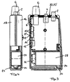
- the embodiment shown in the figures is a portable (microphone) pocket transmitter with the housing according to the invention.
- the Radio includes an electrical circuit (not shown). It has one Socket 2 for an antenna and controls, namely a light indicator 4 for Display of a transmission mode, a controller 6 for regulating the volume Microphone 8, a switch 10 for reception or transmission, a rotary knob 12 for a frequency selection and a control knob 14 for a fine adjustment of the selected frequency.
- the socket 2, the light indicator 4 and the controller 6 occur through omissions in a front panel 20 from the interior of the housing outward.
- the microphone 8, the switch 10, the rotary knob 12 and the control knob 14 are accessible to the user for operation on a narrow side by in Omissions of a side plate 22 designed as a further front plate are included are.
- a battery compartment 24 in which batteries 26 and 28 are inserted.
- the housing consists of a lower housing shell 16 and an upper housing shell 18.
- the housing shells 16, 18 are castings that are used to hold the Front plate 20 and the side plate 22 have a guide.
- the front panel 20 with the controls already mounted therein 2, 4, 6 and the side plate 22 with the control elements mounted therein 8, 10, 12, 14 inserted into the corresponding guide of the lower housing shell 16.
- the upper housing shell is placed on the lower housing shell, the guide provided for this the corresponding area of the front panel 20 or the side plate 22 receives.
- the upper housing shell 18 is with the lower housing shell 16 screwed with screws 30.
- the two housing shells 16, 18 and the front plate 20 and the side plate 22 electrically and mechanically connected to a housing unit.
- the radio device shown in Figures 1 and 2 is equipped with a first electrical Circuit (not shown) provided by a power supply two batteries 26 of the "Mignon" type are provided.
- the battery compartment 24 is accordingly designed to accommodate the two mignon batteries. It points Contact elements (not shown) to connect the Mignon batteries 26 to ensure the first electrical circuit (not shown).
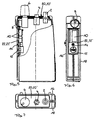
- the radio device shown in FIGS. 3 and 4 has a second electrical one Circuit (not shown), for the power supply of a battery of Type "button battery” is required.
- the battery compartment 24 has an attached therein Support element 34, which clamps the button battery 28 in the battery compartment 24, and a button strip 32 removable from the battery compartment 24, the Contact buttons by cable with the electrical circuit (not shown) of the Two-way radio are connected.
- the modified front panel can be required when manufacturing the radio 20 'or side panel 22' instead of the original front panel 20 and / or Side plate 22 between the lower 16 and the upper housing shell 18 in the Leadership can be used.
Abstract
Description
Die Erfindung betrifft ein Gehäuse für ein tragbares elektrisches Gerät zur Übertragung von Signalen, insbesondere von Tonsignalen, mit einem Fach zur Aufnahme von Batterien und/oder Akkumulatoren für eine Spannungsversorgung des Gerätes und von Anschlüssen zum Anschluß der Batterien an das Gerät, einem Bereich für Bedienorgane zum Bedienen des Gerätes und wenigstens einem Frontplattenbereich zur Aufnahme einer Frontplatte zum Ablesen von Einstellungen der Bedienorgane.The invention relates to a housing for a portable electrical device for transmission of signals, in particular sound signals, with a compartment for recording of batteries and / or accumulators for a voltage supply of the Device and of connections for connecting the batteries to the device, a Area for controls for operating the device and at least one front panel area to accommodate a front panel to read the settings of the Controls.
Gehäuse der vorstehenden Art sind als Gehäuse eines tragbaren elektrischen Geräts z.B. eines drahtlosen Mikrofon-Senders bekannt. Sie dienen der Aufnahme einer elektrischen Schaltung des Geräts, von Batterien bzw. Akkumulatoren zur Spannungsversorgung der elektrischen Schaltung, und Bedienorganen zum Steuern der elektrischen Schaltung durch den Benutzer.Housings of the above type are designed as a portable electrical housing Devices e.g. a wireless microphone transmitter known. They are used for recording an electrical circuit of the device, of batteries or accumulators Power supply to the electrical circuit, and controls for control the electrical circuit by the user.
Bei tragbaren elektrischen Geräten mit dem bekannten Gehäuse ist je nach eingebauter elektrischer Schaltung die Spannungsversorgung der Schaltung durch Batterien eines bestimmten Typs vorgesehen. Das Batteriefach zur Aufnahme dieser Batterien ist an die Form bzw. Größe ihres Typs angepaßt und für die Aufnahme von entsprechenden Anschlüssen zum Anschluß der Batterien dieses Typs ausgebildet. Bei den bekannten Gehäusen ist ferner der Frontplattenbereich an die aufzunehmende Frontplatte angepaßt, die ihrerseits speziell zum Steuern der Bedienorgane der elektrischen Schaltung ausgebildet ist.In portable electrical devices with the known housing is installed depending on electrical circuit through the voltage supply of the circuit Batteries of a certain type are provided. The battery compartment for recording these batteries are adapted to the shape or size of their type and for the Inclusion of appropriate connections for connecting the batteries this Type trained. In the known housings, the front panel area is also adapted to the front panel to be recorded, which in turn specifically for controlling the Control elements of the electrical circuit is formed.
Die bekannten Gehäuse sind nachteilig, weil sie sowohl bezüglich des Batteriefachs als auch bezüglich des Frontplattenbereichs zum Ablesen von Einstellungen der Bedienorgane ausschließlich für einen Einbau und einen Betrieb einer bestimmten elektrischen Schaltung ausgelegt sind. Verschiedene Schaltungen, wie sie beispielsweise bei einer Weiterentwicklung einer ursprünglichen Schaltung entstehen, können zwar u.U. mit verschiedenen Bedienorganen in das bekannte Gehäuse eingesetzt werden, aber der Frontplattenbereich zur Aufnahme der den Bedienorganen entsprechenden Frontplatte sowie das Batteriefach zur Aufnahme der Batterien für eine Spannungsversorgung der jeweiligen elektrischen Schaltung des Gehäuses müssen angepaßt werden. Das Anpassen verursacht in der Entwicklung und Produktion verschiedener Geräte jeweils Kosten, die besonders unerwünscht sind, wenn es sich bei den Geräten um schlichte Weiterentwicklungen desselben Ursprungsgerätes handelt.The known housings are disadvantageous because they both with regard to the battery compartment as well as regarding the front panel area for reading the settings of the Control elements only for the installation and operation of a specific one electrical circuit are designed. Different circuits, such as those arise from a further development of an original circuit, may be with various controls in the well-known housing be used, but the front panel area to accommodate the controls corresponding front panel and the battery compartment for holding the batteries for a voltage supply of the respective electrical circuit of the housing have to be adjusted. Adaptation causes in development and production different devices, costs that are particularly undesirable, if the devices are simple further developments of the same original device acts.
In der DE 37 90 276 T1 (WO 87/07435) ist ein Batteriefach offenbart, das zur wahlweisen und abwechselnden Aufnahme einer Lithium-Batterie mit an einer ersten Endfläche angeordneten Plus- und Minuspolen sowie von Alkali-Mangan-Batterien vorgesehen ist, bei denen die Pluspole bzw. Minuspole an einander abgewandten ersten Endflächen bzw. zweiten Endflächen angeordnet sind. Das offenbarte Batteriefach kann demnach wahlweise unterschiedliche Batterietypen mit unterschiedlichen Höhen und unterschiedlicher Anordnung der Plus- und Minuspole aufnehmen. Das Batteriefach weist u.a. Distanzelemente auf, welche wahlweise eine geschlossene Position (wenn eine Batterie in das Batteriefach eingesetzt ist) oder eine offene Position (bei der das Distanzelement in eine vom Batteriefach entfernte Position bewegt ist) einnehmen kann.DE 37 90 276 T1 (WO 87/07435) discloses a battery compartment which is used for optional and alternating inclusion of a lithium battery with one plus and minus poles arranged on the first end face and of alkaline-manganese batteries is provided in which the plus poles or minus poles to each other facing away from first end surfaces or second end surfaces. The disclosed battery compartment can therefore optionally different battery types with different heights and different arrangement of the plus and Record negative poles. The battery compartment has Spacer elements on which optionally a closed position (if a battery is in the battery compartment inserted) or an open position (in which the spacer element in one of the Battery compartment distant position is moved).
Das bekannte Batteriefach ist zwar flexibel, weil es die wahlweise Aufnahme verschiedener Batterietypen erlaubt. Diese Flexibilität ist jedoch nicht auszunutzen, wenn zur Spannungsversorgung des Gerätes mit einer gegebenen elektrischen Schaltung nur ein bestimmter Batterietyp vorgesehen ist. Die beweglichen Distanzelemente des bekannten Batteriefaches sind nachteilig, weil sie zusätzliche Teile sind, die bei der Herstellung eines mit dem Batteriefach versehenen Gehäuses zusätzliche Kosten verursachen und beim Gebrauch des Geräts eine zusätzliche Quelle von Schäden bilden können. The well-known battery compartment is flexible because it is the optional recording different types of batteries allowed. However, this flexibility cannot be exploited, if to power the device with a given electrical Circuit only a certain battery type is provided. The movable spacer elements the known battery compartment are disadvantageous because they have additional parts are in the manufacture of a housing provided with the battery compartment cause additional costs and an additional when using the device Can form source of damage.
Der Erfindung liegt die Aufgabe zugrunde, ein Gehäuse für ein tragbares, elektrisches Gerät zu schaffen, das besonders kostengünstig herstellbar und einfach zu gebrauchen ist.The invention has for its object a housing for a portable, electrical To create device that is particularly inexpensive to manufacture and easy to use.
Diese Aufgabe wird durch ein Gehäuse für ein tragbares, elektrisches Gerät mit einem Batteriefach gelöst, das für eine alternative Aufnahme von Batterien wenigstens zweier verschiedenen Typen bzw. Größen vorgesehen ist und in dem die Anschlüsse wahlweise zum Anschluß von Batterien der verschiedenen Typen verlegbar sind.This task is accomplished with a housing for a portable electrical device a battery compartment solved that at least for an alternative storage of batteries two different types or sizes is provided and in which the Connections optionally for connecting batteries of different types are relocatable.
Mit der Erfindung erhält man ein Gehäuse, das sich für verschiedene tragbare, elektrische Geräte eignet. Insbesondere eignet sich das Gehäuse zur Aufnahme der Batterien verschiedenen Typs für die Spannungsversorgung verschiedener elektrischer Schaltungen. Dem in das Batteriefach des erfindungsgemäßen Gehäuses einzusetzenden Batterietyp entsprechend werden bei der Herstellung des jeweiligen Gerätes in dem Batteriefach Anschlüsse verlegt, um die vorgesehene Spannungsversorgung der elektrischen Schaltung des Gerätes zu ermöglichen. Das Gehäuse, bzw. Gehäuseschalen, aus denen das Gehäuse zusammengesetzt ist, sind darum vielseitig für verschiedene Geräte verwendbar.The invention provides a housing which can be used for various portable, electrical devices. The housing is particularly suitable for receiving the Batteries of different types for the power supply of various electrical Circuits. That in the battery compartment of the housing according to the invention The type of battery to be used will be appropriate in the manufacture of each Device in the battery compartment connections laid to the intended power supply to enable the electrical circuit of the device. The housing, or housing shells from which the housing is composed are therefore versatile for different devices.
Bei einer Ausführungsform des Gehäuses ist sein Frontplattenbereich für eine wahlweise Aufnahme verschiedener Frontplatten zum Ablesen von Einstellungen der Bedienorgane vorgesehen. Die den Bedienorganen des jeweiligen elektrischen Gerätes entsprechende Frontplatte wird vorzugsweise bei der Fertigung des Gerätes elektrisch und mechanisch zu einer Einheit mit dem Gehäuse verbunden.In one embodiment of the housing, its front panel area is for one Optional inclusion of various front panels for reading settings of the controls. The controls of the respective electrical Device corresponding front panel is preferably used in the manufacture of the device electrically and mechanically connected to the unit to form a unit.
Bei einer anderen Ausführungsform des erfindungsgemäßen Gehäuses ist die Frontplatte an dem Gehäuse lösbar befestigt bzw. von dem Gehäuse lösbar eingefaßt, so daß der Benutzer die Frontplatte austauschen kann, wenn etwa das Gerät um ein Bedienorgan für die elektrische Schaltung erweitert wird.In another embodiment of the housing according to the invention Front plate detachably attached to the housing or detachably framed by the housing, so that the user can replace the front panel when the device is about a control element for the electrical circuit is expanded.
Das Gerät mit dem erfindungsgemäßen Gehäuse ist beispielsweise ein (Mikrofon-)Taschensender, Taschenempfänger und/oder ein Funkgerät etwa zur Übertragung von Ton- und/oder anderen Signalen mit Hochfrequenzwellen oder Infrarotlicht. Bei derartigen Geräten sind üblicherweise die Innovationszyklen so kurz, daß ständig neue Schaltungen entwickelt werden, für die eine Spannungsversorgung durch verschiedene Batterietypen vorgesehen sein kann und die ggf. verschiedene Bedienorgane zu ihrer Steuerung aufweisen. Das erfindungsgemäße Gehäuse läßt sich universell für eine Vielzahl solcher Geräte verwenden. Die Entwicklungskosten und die Kosten für die Umstellung der Produktion für das tragbare elektrische Gerät sind darum besonders niedrig, wenn die neu entwickelte elektrische Schaltung für eine Aufnahme in dem erfindungsgemäßen Gehäuse vorgesehen ist.The device with the housing according to the invention is, for example, a (microphone) bodypack transmitter, Pocket receiver and / or a radio, for example for transmission of sound and / or other signals with radio frequency waves or infrared light. With such devices, the innovation cycles are usually so short that New circuits are constantly being developed for which a voltage supply can be provided by different types of batteries and possibly different ones Have controls for their control. The housing according to the invention can can be used universally for a large number of such devices. The development costs and the cost of switching production for the portable electrical device are therefore particularly low when the newly developed electrical circuit for a receptacle is provided in the housing according to the invention.
Nachfolgend wird ein Ausführungsbeispiel des erfindungsgemäßen Gehäuses anhand der Figuren näher erläutert. Es zeigen:
- Fig. 1
- eine Vorderansicht eines Schnittes durch ein Gerät mit dem erfindungsgemäßen Gehäuse mit darin aufgenommenen Batterien eines ersten Typs;
- Fig. 2
- eine Seitenansicht, teilweise im Schnitt, des Gerätes mit den Batterien des ersten Typs;
- Fig. 3
- eine Vorderansicht eines Schnittes durch das Gerät mit einer Batterie eines zweiten Typs;
- Fig. 4
- eine Seitenansicht, teilweise im Schnitt, des Geräts mit der Batterie des zweiten Typs;
- Fig. 5
- eine Vorderansicht, teilweise im Schnitt, des tragbaren elektrischen Geräts;
- Fig. 6
- eine Seitenansicht des tragbaren elektrischen Geräts; und
- Fig. 7
- eine Draufsicht auf das tragbare elektrische Gerät.
- Fig. 1
- a front view of a section through a device with the housing according to the invention with batteries of a first type accommodated therein;
- Fig. 2
- a side view, partly in section, of the device with the batteries of the first type;
- Fig. 3
- a front view of a section through the device with a battery of a second type;
- Fig. 4
- a side view, partly in section, of the device with the battery of the second type;
- Fig. 5
- a front view, partly in section, of the portable electrical device;
- Fig. 6
- a side view of the portable electrical device; and
- Fig. 7
- a top view of the portable electrical device.
Bei dem in den Figuren dargestellten Ausführungsbeispiel handelt es sich um einen
tragbaren (Mikrofon-)Taschensender mit dem erfindungsgemäßen Gehäuse. Das
Funkgerät beinhaltet eine elektrische Schaltung (nicht dargestellt). Es weist eine
Buchse 2 für eine Antenne auf und Bedienorgane, nämlich eine Leuchtanzeige 4 zur
Anzeige eines Sendebetriebs, einen Regler 6 zum Regeln der Lautstärke, ein
Mikrofon 8, einen Schalter 10 für Empfangs- bzw. Sendebetrieb, einen Drehknopf
12 für eine Frequenzwahl sowie einen Stellknopf 14 für eine Feineinstellung der
ausgewählten Frequenz. Die Buchse 2, die Leuchtanzeige 4 sowie der Regler 6
treten durch Auslassungen in einer Frontplatte 20 aus dem Inneren des Gehäuses
nach außen. Das Mikrofon 8, der Schalter 10, der Drehknopf 12 und der Stellknopf
14 sind dem Benutzer zur Bedienung an einer Schmalseite zugänglich, indem sie in
Auslassungen einer als weitere Frontplatte ausgebildeten Seitenplatte 22 aufgenommen
sind. In einem der Frontplatte 20 gegenüberliegenden Bereich des Gehäuses
befindet sich ein Batteriefach 24, in dem Batterien 26 bzw. 28 eingesetzt sind.The embodiment shown in the figures is a
portable (microphone) pocket transmitter with the housing according to the invention. The
Radio includes an electrical circuit (not shown). It has one
Das Gehäuse besteht aus einer unteren Gehäuseschale 16 und einer oberen Gehäuseschale
18. Die Gehäuseschalen 16, 18 sind Gußteile, die zur Aufnahme der
Frontplatte 20 bzw. der Seitenplatte 22 eine Führung aufweisen. Bei der Fertigung
des Funkgerätes werden die Frontplatte 20 mit den darin bereits montierten Bedienorganen
2, 4, 6 sowie die Seitenplatte 22 mit den darin montierten Bedienorganen
8, 10, 12, 14 in die entsprechende Führung der unteren Gehäuseschale 16 eingesetzt.
Die obere Gehäuseschale wird auf die untere Gehäuseschale aufgesetzt,
wobei die dafür vorgesehene Führung den entsprechenden Bereich der Frontplatte
20 bzw. der Seitenplatte 22 aufnimmt. Die obere Gehäuseschale 18 wird mit der
unteren Gehäuseschale 16 mit Schrauben 30 festgeschraubt. Dabei werden die
beiden Gehäuseschalen 16, 18 sowie die Frontplatte 20 und die Seitenplatte 22
elektrisch und mechanisch zu einer Gehäuseeinheit verbunden.The housing consists of a
Das in den Figuren 1 und 2 dargestellte Funkgerät ist mit einer ersten elektrischen
Schaltung (nicht dargestellt) versehen, die für eine Spannungsversorgung durch
zwei Batterien 26 vom Typ "Mignon" vorgesehen ist. Das Batteriefach 24 ist
dementsprechend zur Aufnahme der zwei Mignon-Batterien ausgebildet. Es weist
Kontaktelemente (nicht dargestellt) auf, um einen Anschluß der Mignon-Batterien
26 an die erste elektrische Schaltung (nicht dargestellt) zu gewährleisten.The radio device shown in Figures 1 and 2 is equipped with a first electrical
Circuit (not shown) provided by a power supply
two batteries 26 of the "Mignon" type are provided. The
Das in den Fig. 3 und 4 dargestellte Funkgerät weist eine zweite elektrische
Schaltung (nicht dargestellt) auf, zu deren Spannungsversorgung eine Batterie des
Typs "Knopfbatterie" erforderlich ist. Das Batteriefach 24 weist ein darin befestigtes
Stützelement 34 auf, das die Knopfbatterie 28 in dem Batteriefach 24 einklemmt,
und eine aus dem Batteriefach 24 herausnehmbare Knopfleiste 32, deren
Kontaktknöpfe durch Kabel mit der elektrischen Schaltung (nicht dargestellt) des
Funkgeräts verbunden sind.The radio device shown in FIGS. 3 and 4 has a second electrical one
Circuit (not shown), for the power supply of a battery of
Type "button battery" is required. The
Wenn für die zweite elektrische Schaltung eine gegenüber der Frontplatte 20
und/oder der Seitenplatte 22 veränderte Frontplatte 20' und/oder Seitenplatte 22'
erforderlich ist, kann bei der Fertigung des Funkgeräts die veränderte Frontplatte
20' bzw. Seitenplatte 22' anstelle der ursprünglichen Frontplatte 20 und/oder
Seitenplatte 22 zwischen der unteren 16 und der oberen Gehäuseschale 18 in die
Führung eingesetzt werden.If for the second electrical circuit one opposite the front panel 20
and / or the
Claims (5)
dadurch gekennzeichnet,
daß das Fach (24) für eine alternative Aufnahme von Batterien (26, 28) wenigstens zweier verschiedenen Typen bzw. Größen vorgesehen ist und in dem die Anschlüsse wahlweise zum Anschluß von Batterien (26, 28) der verschiedenen Typen verlegbar bzw. verlegt sind.Housing for a portable, electrical device for transmitting signals, in particular audio signals, with a compartment (24) for receiving batteries and / or accumulators for supplying power to the device and connections for connecting the batteries to the device, a receptacle for operating elements (4, 6, 8, 10, 12, 14) for operating the device and at least one front panel area for receiving a front panel (20, 22) for reading settings of the operating elements (4, 6, 8, 10, 12, 14),
characterized,
that the compartment (24) is provided for an alternative accommodation of batteries (26, 28) of at least two different types or sizes and in which the connections can be laid or laid optionally for connecting batteries (26, 28) of the different types.
dadurch gekennzeichnet,
daß der Frontplattenbereich für eine wahlweise Aufnahme verschiedener Frontplatten (20, 20', 22, 22') vorgesehen ist.Housing according to claim 1,
characterized,
that the front panel area is provided for an optional mounting of different front panels (20, 20 ', 22, 22').
dadurch gekennzeichnet,
daß der Frontplattenbereich für eine derartige Befestigung der Frontplatte (20, 20', 22, 22') an dem Gehäuse vorgesehen ist, daß diese mit dem Gehäuse eine elektrische und mechanische Einheit bildet.Housing according to claim 2,
characterized,
that the front panel area is provided for fastening the front panel (20, 20 ', 22, 22') to the housing such that it forms an electrical and mechanical unit with the housing.
dadurch gekennzeichnet,
daß der Frontplattenbereich für eine lösbare Befestigung der Frontplatte (20, 20', 22, 22') ausgebildet ist.Housing according to claim 2,
characterized,
that the front panel area is designed for releasable attachment of the front panel (20, 20 ', 22, 22').
Applications Claiming Priority (2)
| Application Number | Priority Date | Filing Date | Title |
|---|---|---|---|
| DE29916458U DE29916458U1 (en) | 1999-09-18 | 1999-09-18 | Housing for a portable electrical device |
| DE29916458U | 1999-09-18 |
Publications (2)
| Publication Number | Publication Date |
|---|---|
| EP1085588A1 true EP1085588A1 (en) | 2001-03-21 |
| EP1085588B1 EP1085588B1 (en) | 2005-08-24 |
Family
ID=8079110
Family Applications (1)
| Application Number | Title | Priority Date | Filing Date |
|---|---|---|---|
| EP00113441A Expired - Lifetime EP1085588B1 (en) | 1999-09-18 | 2000-06-24 | Housing comprising a battery compartment for a portable electric device |
Country Status (4)
| Country | Link |
|---|---|
| EP (1) | EP1085588B1 (en) |
| AT (1) | ATE302998T1 (en) |
| CA (1) | CA2315931A1 (en) |
| DE (2) | DE29916458U1 (en) |
Families Citing this family (6)
| Publication number | Priority date | Publication date | Assignee | Title |
|---|---|---|---|---|
| GB2373953B (en) * | 2000-12-29 | 2004-10-06 | Nokia Mobile Phones Ltd | A casing |
| US7454014B2 (en) | 2000-12-29 | 2008-11-18 | Vertu Limited | Device with a loudspeaker and an ear piece cover |
| GB2373952B (en) | 2000-12-29 | 2004-10-27 | Nokia Mobile Phones Ltd | A casing |
| DE10155917A1 (en) * | 2001-11-12 | 2003-05-15 | Heidenhain Gmbh Dr Johannes | probe |
| US7687197B2 (en) | 2005-10-07 | 2010-03-30 | Research In Motion Limited | Expandable battery compartment for handheld electronic devices |
| ATE430337T1 (en) * | 2005-10-07 | 2009-05-15 | Research In Motion Ltd | VERSATILE BATTERY COMPARTMENT FOR PORTABLE DEVICES |
Citations (6)
| Publication number | Priority date | Publication date | Assignee | Title |
|---|---|---|---|---|
| US4431717A (en) * | 1981-01-31 | 1984-02-14 | Sony Corporation | Battery case |
| JPH06244743A (en) * | 1993-02-19 | 1994-09-02 | Matsushita Seiko Co Ltd | Transmitter for wireless remote controller |
| JPH0722010A (en) * | 1993-06-30 | 1995-01-24 | Casio Comput Co Ltd | Battery-container structure |
| US5384207A (en) * | 1992-07-15 | 1995-01-24 | Matsushita Electric Industrial Co., Ltd. | Electronic apparatus with battery power source |
| US5780992A (en) * | 1995-08-09 | 1998-07-14 | Norand Corporation | Rechargeable battery system adaptable to a plurality of battery types |
| US5980310A (en) * | 1997-02-10 | 1999-11-09 | Alcatel | Power supply unit for portable apparatus and of the type enabling various types of power source to be used, and corresponding portable apparatus |
-
1999
- 1999-09-18 DE DE29916458U patent/DE29916458U1/en not_active Expired - Lifetime
-
2000
- 2000-06-24 DE DE50011016T patent/DE50011016D1/en not_active Expired - Lifetime
- 2000-06-24 AT AT00113441T patent/ATE302998T1/en not_active IP Right Cessation
- 2000-06-24 EP EP00113441A patent/EP1085588B1/en not_active Expired - Lifetime
- 2000-08-14 CA CA002315931A patent/CA2315931A1/en not_active Abandoned
Patent Citations (6)
| Publication number | Priority date | Publication date | Assignee | Title |
|---|---|---|---|---|
| US4431717A (en) * | 1981-01-31 | 1984-02-14 | Sony Corporation | Battery case |
| US5384207A (en) * | 1992-07-15 | 1995-01-24 | Matsushita Electric Industrial Co., Ltd. | Electronic apparatus with battery power source |
| JPH06244743A (en) * | 1993-02-19 | 1994-09-02 | Matsushita Seiko Co Ltd | Transmitter for wireless remote controller |
| JPH0722010A (en) * | 1993-06-30 | 1995-01-24 | Casio Comput Co Ltd | Battery-container structure |
| US5780992A (en) * | 1995-08-09 | 1998-07-14 | Norand Corporation | Rechargeable battery system adaptable to a plurality of battery types |
| US5980310A (en) * | 1997-02-10 | 1999-11-09 | Alcatel | Power supply unit for portable apparatus and of the type enabling various types of power source to be used, and corresponding portable apparatus |
Non-Patent Citations (2)
| Title |
|---|
| PATENT ABSTRACTS OF JAPAN vol. 018, no. 629 (E - 1637) 30 November 1994 (1994-11-30) * |
| PATENT ABSTRACTS OF JAPAN vol. 1995, no. 04 31 May 1995 (1995-05-31) * |
Also Published As
| Publication number | Publication date |
|---|---|
| ATE302998T1 (en) | 2005-09-15 |
| EP1085588B1 (en) | 2005-08-24 |
| DE29916458U1 (en) | 2000-01-13 |
| CA2315931A1 (en) | 2001-03-18 |
| DE50011016D1 (en) | 2005-09-29 |
Similar Documents
| Publication | Publication Date | Title |
|---|---|---|
| EP3154106B1 (en) | Power tool | |
| EP0591791B1 (en) | Programmable hearing-aid | |
| EP0129788B1 (en) | Hearing aid | |
| EP0613092A1 (en) | Portable electronic device for orientation and communication | |
| DE102004062177B4 (en) | Holding device for receiving a mobile phone | |
| EP0136643A2 (en) | Hearing aid | |
| EP1737704A1 (en) | Car radio with removable mpeg-player | |
| EP0504703A2 (en) | Hearing aid with electrical contact means within a battery holder | |
| DE2702129A1 (en) | Charger for portable radio communications battery - has adaptors to match different batteries to connection recess | |
| CH667355A5 (en) | CORDLESS TELEPHONE. | |
| EP1085588B1 (en) | Housing comprising a battery compartment for a portable electric device | |
| EP0176617B1 (en) | Electronic time switch | |
| DE102017103194A1 (en) | battery Pack | |
| DE3515434C2 (en) | ||
| DE3228700A1 (en) | Portable electronic apparatus | |
| EP0521329A1 (en) | In-the-ear hearing aid and production method | |
| DE3105834A1 (en) | Light regulator | |
| DE202005022111U1 (en) | Battery pack and electric hand tool | |
| DE202017100890U1 (en) | Clamping device and mobile power supply | |
| DE3706186A1 (en) | Device for obtaining and storing electrical energy from solar energy | |
| EP0473748B1 (en) | Time switch clock | |
| DE3711504C2 (en) | ||
| DE19947064C2 (en) | Car holder for mobile devices | |
| EP0580886A1 (en) | Portable transmitter providing remote control of a locking means, in particular adapted to an automobile | |
| DE19549398C2 (en) | Loading device |
Legal Events
| Date | Code | Title | Description |
|---|---|---|---|
| PUAI | Public reference made under article 153(3) epc to a published international application that has entered the european phase |
Free format text: ORIGINAL CODE: 0009012 |
|
| AK | Designated contracting states |
Kind code of ref document: A1 Designated state(s): AT DE FR GB IT |
|
| AX | Request for extension of the european patent |
Free format text: AL;LT;LV;MK;RO;SI |
|
| 17P | Request for examination filed |
Effective date: 20010921 |
|
| AKX | Designation fees paid |
Free format text: AT DE FR GB IT |
|
| 17Q | First examination report despatched |
Effective date: 20040601 |
|
| GRAP | Despatch of communication of intention to grant a patent |
Free format text: ORIGINAL CODE: EPIDOSNIGR1 |
|
| GRAS | Grant fee paid |
Free format text: ORIGINAL CODE: EPIDOSNIGR3 |
|
| GRAA | (expected) grant |
Free format text: ORIGINAL CODE: 0009210 |
|
| AK | Designated contracting states |
Kind code of ref document: B1 Designated state(s): AT DE FR GB IT |
|
| REG | Reference to a national code |
Ref country code: GB Ref legal event code: FG4D Free format text: NOT ENGLISH |
|
| GBT | Gb: translation of ep patent filed (gb section 77(6)(a)/1977) |
Effective date: 20050824 |
|
| REF | Corresponds to: |
Ref document number: 50011016 Country of ref document: DE Date of ref document: 20050929 Kind code of ref document: P |
|
| ET | Fr: translation filed | ||
| PLBE | No opposition filed within time limit |
Free format text: ORIGINAL CODE: 0009261 |
|
| STAA | Information on the status of an ep patent application or granted ep patent |
Free format text: STATUS: NO OPPOSITION FILED WITHIN TIME LIMIT |
|
| 26N | No opposition filed |
Effective date: 20060526 |
|
| PGFP | Annual fee paid to national office [announced via postgrant information from national office to epo] |
Ref country code: AT Payment date: 20090622 Year of fee payment: 10 |
|
| PGFP | Annual fee paid to national office [announced via postgrant information from national office to epo] |
Ref country code: FR Payment date: 20090618 Year of fee payment: 10 |
|
| PGFP | Annual fee paid to national office [announced via postgrant information from national office to epo] |
Ref country code: GB Payment date: 20090623 Year of fee payment: 10 |
|
| PGFP | Annual fee paid to national office [announced via postgrant information from national office to epo] |
Ref country code: IT Payment date: 20090627 Year of fee payment: 10 |
|
| GBPC | Gb: european patent ceased through non-payment of renewal fee |
Effective date: 20100624 |
|
| REG | Reference to a national code |
Ref country code: FR Ref legal event code: ST Effective date: 20110228 |
|
| PG25 | Lapsed in a contracting state [announced via postgrant information from national office to epo] |
Ref country code: IT Free format text: LAPSE BECAUSE OF NON-PAYMENT OF DUE FEES Effective date: 20100624 |
|
| PG25 | Lapsed in a contracting state [announced via postgrant information from national office to epo] |
Ref country code: FR Free format text: LAPSE BECAUSE OF NON-PAYMENT OF DUE FEES Effective date: 20100630 Ref country code: AT Free format text: LAPSE BECAUSE OF NON-PAYMENT OF DUE FEES Effective date: 20100624 |
|
| PG25 | Lapsed in a contracting state [announced via postgrant information from national office to epo] |
Ref country code: GB Free format text: LAPSE BECAUSE OF NON-PAYMENT OF DUE FEES Effective date: 20100624 |
|
| PGFP | Annual fee paid to national office [announced via postgrant information from national office to epo] |
Ref country code: DE Payment date: 20150610 Year of fee payment: 16 |
|
| REG | Reference to a national code |
Ref country code: DE Ref legal event code: R119 Ref document number: 50011016 Country of ref document: DE |
|
| PG25 | Lapsed in a contracting state [announced via postgrant information from national office to epo] |
Ref country code: DE Free format text: LAPSE BECAUSE OF NON-PAYMENT OF DUE FEES Effective date: 20170103 |