EP1085167A2 - Polycrystaline diamond compact insert reaming tool - Google Patents
Polycrystaline diamond compact insert reaming tool Download PDFInfo
- Publication number
- EP1085167A2 EP1085167A2 EP00119792A EP00119792A EP1085167A2 EP 1085167 A2 EP1085167 A2 EP 1085167A2 EP 00119792 A EP00119792 A EP 00119792A EP 00119792 A EP00119792 A EP 00119792A EP 1085167 A2 EP1085167 A2 EP 1085167A2
- Authority
- EP
- European Patent Office
- Prior art keywords
- blades
- reaming
- drill
- diameter
- pilot
- Prior art date
- Legal status (The legal status is an assumption and is not a legal conclusion. Google has not performed a legal analysis and makes no representation as to the accuracy of the status listed.)
- Granted
Links
- 229910003460 diamond Inorganic materials 0.000 title description 5
- 239000010432 diamond Substances 0.000 title description 5
- 230000003750 conditioning effect Effects 0.000 claims abstract description 30
- 238000005553 drilling Methods 0.000 claims abstract description 15
- 239000013256 coordination polymer Substances 0.000 claims description 19
- 230000015572 biosynthetic process Effects 0.000 claims description 5
- 238000005755 formation reaction Methods 0.000 claims description 5
- 238000005520 cutting process Methods 0.000 description 11
- 239000004568 cement Substances 0.000 description 3
- 229910000831 Steel Inorganic materials 0.000 description 2
- 239000012530 fluid Substances 0.000 description 2
- 239000000463 material Substances 0.000 description 2
- 238000000034 method Methods 0.000 description 2
- 239000003208 petroleum Substances 0.000 description 2
- 239000010959 steel Substances 0.000 description 2
- UONOETXJSWQNOL-UHFFFAOYSA-N tungsten carbide Chemical compound [W+]#[C-] UONOETXJSWQNOL-UHFFFAOYSA-N 0.000 description 2
- ZPUCINDJVBIVPJ-LJISPDSOSA-N cocaine Chemical compound O([C@H]1C[C@@H]2CC[C@@H](N2C)[C@H]1C(=O)OC)C(=O)C1=CC=CC=C1 ZPUCINDJVBIVPJ-LJISPDSOSA-N 0.000 description 1
- 230000001681 protective effect Effects 0.000 description 1
Images


Classifications
-
- E—FIXED CONSTRUCTIONS
- E21—EARTH DRILLING; MINING
- E21B—EARTH DRILLING, e.g. DEEP DRILLING; OBTAINING OIL, GAS, WATER, SOLUBLE OR MELTABLE MATERIALS OR A SLURRY OF MINERALS FROM WELLS
- E21B10/00—Drill bits
- E21B10/26—Drill bits with leading portion, i.e. drill bits with a pilot cutter; Drill bits for enlarging the borehole, e.g. reamers
- E21B10/265—Bi-center drill bits, i.e. an integral bit and eccentric reamer used to simultaneously drill and underream the hole
Definitions
- the invention is related to the field of reaming tools used to enlarge the diameter of wellbores drilled through the earth beyond the diameter of a drill bit used to initially drill the wellbore through earth.
- Drill bits used to drill wellbores through earth formations typically have a nominal diameter, that is, a diameter of a borehole that will be created when the drill bit is rotated and impressed axially onto the formations. Frequently it is desirable to enlarge the diameter of the borehole beyond the nominal diameter of the drill bit.
- Specialized drill bits known as bi-center bits, have been developed to create boreholes having drilled diameters greater than the diameter of an opening through which such bits will pass when they are not rotated.
- Other tools for enlarging a borehole beyond the nominal diameter of a symmetric bit include reamer wings.
- Reamer wings are typically assembled to a drilling tool assembly (drill string) at a selected axial position behind (away from the drilling surface) the drill bit.
- Reamer wings have cutting elements positioned on blades which extend radially outward from the rotational center of the drill string to a greater distance therefrom than the radius of the drill bit. When the reamer wing is rotated, the cutting elements drill the enlarged borehole.
- Reamer wings are described for example in U. S. patents nos. 5,495,899 issued to Pastusek et al, 5,497,842 issued to Pastusek et al, and 5,765,653 issued to Doster et al.
- Reamer wings typically include a tubular housing or body having a number of longitudinally extensive, azimuthally spaced apart, and generally radially-extending blades. The blades having cutting elements on them.
- the cutting elements are typically polycrystalline diamond compact inserts, carbide inserts or a combination of these.
- the reamer wings known in the art are susceptible to drilling a borehole in which the surface of the borehole is not smooth and round.
- the reaming wings known in the art are susceptible to damage to the cutting elements affixed to the blades. Still further, the reamer wings known in the art are typically unable to chill out equipment used to cement a steel a casing in place in the borehole (float equipment) without damage to the cutting elements on the blades.
- One aspect of the invention is a reaming tool including a body having reaming blades affixed to the body at azimuthally spaced apart locations.
- the reaming blades have cutters attached to them at selected positions.
- An outermost surface of each one of the reaming blades conforms to a radially least extensive one, with respect to the longitudinal axis of the reaming tool, of a pass through circle and a drill circle.
- the drill circle is substantially coaxial with the longitudinal axis.
- the pass-through circle is axially offset from the drill circle and defines an arcuate section inside which the pass-through circle extends from the longitudinal axis beyond the lateral extent of the drill circle, so that radially outermost cutters disposed on the reaming blades positioned azimuthally within the arcuate section will drill a hole having a drill diameter substantially twice a maximum lateral extension of the reaming blades from the longitudinal axis, while substantially avoiding wall contact along an opening having a diameter of the pass through circle.
- the reaming blades positioned azimuthally outside the arcuate section include wear resistant inserts on their outermost surfaces.
- the inserts are tungsten carbide, polycrystalline diamond or the like.
- a reaming tool including a body having reaming blades affixed to them at azimuthally spaced apart locations.
- the reaming blades have cutters attached to them at selected positions along each one of the reaming blades.
- the reaming tool includes a pilot hole conditioning section having a plurality of azimuthally spaced apart blades ("Pilot blades") affixed to the body longitudinally ahead of the reaming blades.
- the pilot blades include a taper on their downhole ends, a gauge pad having a diameter substantially equal to a drill diameter of a pilot bit used to drill a pilot hole longitudinally ahead of the reaming tool, and an intermediate cutter affixed to selected ones of the pilot blades longitudinally behind the gauge pad.
- the intermediate cutters are positioned laterally so as to drill a hole having an intermediate diameter larger than the pilot hole diameter and smaller than a drill diameter of the reaming tool.
- the pilot blades include an intermediate gauge pad axially "uphole" of the intermediate cutters, if used, these gauge pads having a diameter substantially equal to the intermediate diameter.
- a reaming tool including a body having reaming blades affixed to the body at azimuthally spaced apart locations around the circumference of the body.
- the reaming blades each have at least one cutter attached to them at a selected position along each of the blades, the position and/or orientation of the cutter selected to minimize lateral force imbalance of the reaming tool.
- One embodiment of this aspect of the invention includes a pilot hole conditioning section having a plurality of azimuthally spaced apart pilot blades affixed to the reaming tool body longitudinally ahead of the reaming blades.
- a reaming tool including a body having reaming blades affixed to the body at azimuthally spaced apart locations around a circumference of the body. Selected ones of the reaming blades include cutters attached to them at selected positions.
- the reamer includes a pilot hole conditioning section, including a plurality of azimuthally spaced apart pilot blades affixed to the reamer body longitudinally ahead of the reaming blades. At least one of the reaming blades is formed as a single structure with an azimuthally corresponding one of the pilot blades.
- a reaming tool including a plurality of reaming blades affixed to a body at azimuthally spaced apart locations. Selected ones of the reaming blades are formed as spirals.
- a reaming tool including a body having reaming blades affixed to the body at azimuthally spaced apart locations around a circumference of the body. Selected ones of the reaming blades include cutters on them at selected positions.
- the reaming tool in this aspect also includes a pilot hole conditioning section having a plurality of azimuthally spaced apart pilot blades affixed to the body longitudinally ahead of the reaming blades.
- the pilot blades each include a taper on the downhole end of the blade, a gauge pad having a diameter substantially equal to a drill diameter of a pilot bit used to drill a pilot hole longitudinally ahead of the reaming tool, and at least one intermediate cutter affixed to selected ones of the pilot blades longitudinally behind the gauge pad.
- the at least one intermediate cutter is laterally positioned to drill a hole having an intermediate diameter larger than the pilot hole and smaller than a drill diameter of the reaming tool.
- Selected ones of the pilot blades include an intermediate gauge pad having a diameter substantially equal to the intermediate diameter.
- At least one of a position and an orientation of the at least one intermediate cutter is selected so that net lateral force generated by the reaming tool is within about twenty percent of the axial force (weight on bit) applied to the reaming tool. In another embodiment, the net lateral force is within about 15 percent of the axial force on the reaming tool (weight on bit).
- the pilot blades include a taper on the downhole edge. Selected ones of the tapers can include an auxiliary cutter thereon.
- the reaming tool 10 is formed on a body 12 made of high-strength material.
- the body 12 is adapted to be coupled to a rotary wellbore drill string (not shown), preferably by means of threaded connections 14, 16 machined or otherwise formed into the longitudinal ends of the body 12.
- the body 12 includes a plurality of azimuthally spaced apart blades 22 formed therein or otherwise affixed to the body 12.
- Some of the blades 22 include cutters 124, 224 positioned thereon at spaced apart locations.
- the cutters 124, 224 are preferably polycrystalline diamond compact (PDC) inserts or the like, but other types of cutters such as carbide cutters will work with the invention.
- PDC polycrystalline diamond compact
- the reaming tool 10 includes a plurality of dulling fluid discharge orifices 26 to provide drilling fluid flow during drilling operations to cool the reaming tool 10 and to wash away drill cuttings as earth formations (not shown) are deformed by the cutters 124, 224.
- the reaming tool 10 can be divided into a pilot hole conditioning section 18 and a reaming section 20 each of which will be explained in more detail.
- One purpose of the hole conditioning section 18 is to provide a round, smooth borehole which acts as a thrust surface against which the cutters 224 in the reaming section 20 can push, so that the reaming section 20 drills a hole having a diameter (referred to as the "drill diameter") which is larger than the diameter of an opening through which the reaming tool 10 can freely pass (this diameter referred to as the "pass-through diameter").
- the pilot hole conditioning section 18 is to provide lateral force which balances the lateral forces exerted by the cutters 224 on the reaming section 20, as will he further explained.
- FIG. 2 A side view of the example reaming tool 10 is shown in Figure 2.
- the blades 22 in the pilot hole conditioning section 18 each include on their "downhole" ends (ends nearest threaded connection 14) a taper 28.
- Threaded connection 14 is referred to as the downhole end since it is in the direction of a pilot bit (not shown) which can be directly attached to threaded connection 14 or can be indirectly attached thereto.
- the pilot bit (not shown) as is understood by those skilled in the art, drills a "pilot" hole having a nominal diameter less than the drill diameter of the reaming tool 10. See for example, T. M. Warren et al, Simultaneous Drilling and Reaming with Fixed Blade Reamers, paper no.
- the tapers 28 align the reaming tool 10 with the hole drilled by the pilot bit (not shown).
- the pilot bit (not shown) is not attached directly to the reaming tool 10, and is therefore axially separated from the reaming tool 10 by a substantial distance, it is preferable to include auxiliary cutters 128 on the tapers 28 to facilitate alignment of the reaming tool 10.
- auxiliary cutters 128 on the tapers 28 enables easy passage of the reaming tool 10 along the pilot hole when the longitudinal axis 34 of the reaming tool 10 is not aligned with the pilot hole due to flexure in the drill string between the pilot bit (not shown) and the reaming tool 10.
- the auxiliary cutters 128 also enhance the ability of the reaming tool 10 to properly drill through special equipment ("float equipment") used to cement a steel pipe or casing into a wellbore.
- float equipment special equipment
- Prior art reamer wings did not have good ability to drill through such float equipment without some damage to the casing or to the prior art reamer wing.
- the numbers of, and azimuthal locations of the blades in the pilot hole conditioning section 18 are not meant to limit the invention, but as a practical matter, the reaming tool 10 will perform better if the blades are azimuthally distributed around the circumference of the pilot hole conditioning section 18 in a way which substantially maintains the axial position of the reaming tool 10 concentrically within the pilot hole. It is clearly within the contemplation of this aspect of the invention, for example, that two pilot hole conditioning blades spaced 180 degrees apart, or three pilot hole conditioning section blades spaced 120 degrees apart azimuthally in the pilot hole conditioning section 18 will result in adequate performance of the reaming tool 10.
- Pilot gauge pads 30 in the pilot hole conditioning section 18 help to maintain axial alignment of the reaming toot 10 in the pilot hole.
- pilot holes can be enlarged beyond the diameter of the pilot bit (not shown), out of round, rugose, or otherwise not form a smooth cylindrical surface. This is particularly the case when the pilot bit (not shown) is the roller cone type, as is known in the art.
- One aspect of the invention is the inclusion of cutters 124 in the pilot hole conditioning section 18.
- the pilot hole conditioning section cutters 124 are positioned to drill a hole having a slightly larger diameter than the nominal diameter of the pilot bit (not shown).
- the cutters 124 can be laterally positioned along the pilot hole conditioning section blades to drill an intermediate pilot hole having approximately 9 inch (228.6 mm) diameter.
- the intermediate pilot hole diameter can be maintained by intermediate gauge pads 32 positioned axially "uphole” (away from the pilot bit) from the pilot hole conditioning section cutters 124.
- the pilot hole conditioning section cutters 124, and the intermediate gauge pads 32 provide a smooth, round, selected diameter thrust surface against which the reaming section 20 can then drill a hole having the selected drill diameter of the reaming tool 10.
- the example diameters for the pilot hole and intermediate pilot hole are only meant as examples and are not meant to limit this aspect of the invention.
- the positions and orientations of the pilot hole conditioning section cutters 124 on the pilot blades are preferably selected to provide a lateral force which nearly matches in magnitude and offsets in azimuthal direction, a net lateral force exerted by all the cutters 224 on the reaming section 20.
- Methods for selecting positions and orientations to achieve the desired force balance are known in the art. See for example, T. M. Warren et al, Drag Bit Performance Modeling , paper no. 15617,Society of Petroleum Engineers, Richardson, TX, 1986.
- Figure 3 is an end view of the reaming section 20.
- the reaming blades are designated by numerals B1 through B7 to identify them individually.
- the outer surfaces of the reaming blades B1-B7 can first be machined such as on a lathe, or otherwise formed, so as to conform to a circle having the drill diameter, which is twice the largest lateral extent R R shown in Figure 3 from the longitudinal axis 34 of any of the reaming blades B1-B7.
- the drill diameter of the reaming tool 10 is the diameter to which the drill hole will be opened by passage of the reamer blades B1-B7 as the reaming tool 10 rotates about the longitudinal axis 34.
- This conformance circle, the so-called “drill circle”, is shown in Figure 3 at CD.
- the drill circle CD is substantially coaxial with the longitudinal axis 34 of the reaming tool 10, as the reaming tool 10 rotates about the longitudinal axis 34 during drilling.
- the reaming blades B1-B7 are, in addition, shaped so that the reaming tool 10 can pass freely through an opening which is smaller than the chill diameter (2 X R R ) . This diameter is referred to as the "pass through" diameter.
- a circle showing the opening through which the reaming tool 10 will pass is shown in Figure 3 as the "pas-through circle” CP.
- the outer surfaces of the reaming blades B1-B7 after being formed to fit within the drill circle CD, can then be cut such as on a lathe, or otherwise formed, to conform to the pass-through circle CP.
- the pass-through circle CP is axially offset from the drill circle CD (and the longitudinal axis 34) by an amount which results in some overlap between the circumferences of the pass through circle CP and circumference of the drill circle CD.
- intersections of the pass-through circle CP and drill circle CD circumferences are shown at A and B in Figure 3, and the overlapping section ("overlap section") is shown at X.
- overlap section X circumferentially between points A and B, any reaming blades so azimuthally located are shaped to conform to the drill circle CD, as within the overlap section X, the drill circle CD is radially less extensive from the longitudinal axis 34 than is the pass through circle CP.
- blades B1 and B2 are located azimuthally within the overlap section X.
- the reaming blades (B3-B7 in this example) conform to the pass-through circle CP because within this azimuthal range the pass through circle CP is radially less extensive from the longitudinal axis 34 than is the drill circle CD.
- the particular azimuthal locations of the reaming blades B1-B7 shown in Figure 3 are only meant to illustrate the principle by which the reaming blades on the reaming tool 10 are formed.
- the specific azimuthal positions of the reamer blades, and the numbers of such reamer blades within and without the overlap section X shown in Figure 3 are not meant to specifically limit the invention.
- the radially outermost cutters 224A positioned on these blades B1, B2 can then be positioned on the leading edge (the edge of the blade which faces the direction of rotation of the reaming tool 10) thereof so that the cutter locations will trace a circle having the full drill diameter (2 X R R ) when the reaming tool 10 rotates about the longitudinal axis 34.
- the radially most extensive reaming blades B1, B2, however, are positioned azimuthally in the overlap section X, as previously explained.
- the drill circle CD defines, with respect to the longitudinal axis 34, the laterally outermost part of the reaming tool 10 at every azimuthal position, as previously explained. Therefore the blades B1, B2 within the overlap section X will extend only as far laterally as the radius of the drill circle CD.
- the radially outermost cutters 224A on blades B1 and B2 can be positioned at "full gauge", meaning that these cutters 224A are at the same radial distance from the longitudinal axis 34 as the outermost parts of the blade B1, B2 onto which they are attached, and will therefore cut a full drill diameter hole.
- the cutters 224A on blades B1, B2 are also disposed radially inward from the pass-through circle CP at these same azimuthal positions because of the limitation of the lateral extent of these blades B1, B2. Therefore, the outermost cutters 224A will not contact the inner surface of an opening having a diameter about equal to the pass-through diameter as the reaming tool 10 is moved through such an opening.
- the preferred shape of the radially outermost reaming blades B1, B2 and the position of radially outermost cutters 224A thereon enables the reaming tool 10 to pass freely through a protective casing (not shown) inserted into a wellbore, without sustaining damage to the outermost cutters 224A, while at the same time drilling a hole which has the full drill diameter (2 X R R ) .
- non-gauge reaming blades which do not extend to full drill diameter
- the reaming blades which do not extend to full drill diameter referred to as "non-gauge reaming blades"
- reaming blades shown at B3-B7
- This configuration of blades B3-B7 and cutters 224B has proven to be particularly useful in efficiently drilling through equipment (called "float equipment") used to cement in place the previously referred to casing.
- non-gauge reaming blades B3-B7 By positioning the cutters 224B on the non-gauge reaming blades B3-B7 as described herein, damage to these cutters 224B can be avoided. Damage to the casing (not shown) can be also be avoided by arranging the non-gauge cutters 224B as described, particularly when drilling out the float equipment.
- the non-gauge reaming blades B3-B7 are described herein as being formed by causing these blades to conform to the pass-through circle CP, it should be understood that the pass-through circle only represents a radial extension limit for the non-gauge reaming blades B3-B7. It is possible to build the reaming tool 10 with radially shorter non-gauge reaming blades.
- Another aspect of the invention is the use of cutters 224B positioned on the reaming blades B3-B7 located outside the overlap section X.
- Prior art reamer wings typically had blades substantially only on one side of the reamer. Any lateral extensions of prior art reamer wings in azimuthal positions away from the intended cutting area were typically in the form of pads having no cutting structures thereon.
- at least one cutter can be included on each reaming blade B3-B7 located outside the overlap section, even those reaming blades (such as B4-B6 in Figure 3) which are azimuthally substantially opposite the gauge reaming blades B1, B2.
- the azimuthal positions of the blades B1-B7 shown in Figure 3 are only an example of azimuthal positions which will work with this aspect of the invention, but this aspect of the invention will perform better when the blades B1-B7 are distributed around substantially all the circumference of the body 12.
- the cutters 224B on the non-gauge reaming blades B3-B7 should be located radially inboard of the outer edge of the non-gauge reaming blades to avoid damage thereto when the reaming tool 10 is passed through an opening having the pass through diameter.
- the purpose of including the cutters 224B on the non-gauge reaming blades B3-B7 is to provide azimuthally more balanced cutting force to the reaming tool 10 than is possible using only cutters on the gauge reaming blades B1, B2.
- the particular positions and/or orientations of the cutters 224A, 224B are preferably selected to minimize the overall net lateral force generated by the reaming section 20. Methods for selecting cutter orientations and positions are described in the Warren et al reference referred to earlier, for example.
- the reaming section 20 will develop some net lateral force during drilling of earth formations.
- the net lateral force is a result of having a much larger number of cutters 224 concentrated on the gauge reaming blades B1, B2.
- the positions and/or orientations of the intermediate gauge cutters (124 in Figure 2) on the pilot hole conditioning section (18 in Figure 2) are be selected to provide a net lateral force imbalance which within about twenty percent of axial force (referred to in the art as "weight on bit”) applied to the reaming tool 10. More preferably, the net lateral force should be within about fifteen percent of the axial force on the reaming tool 10.
- weight on bit referred to in the art as "weight on bit”
- Another aspect of the invention is the shape of the reaming blades B1-B7.
- the preferred shape is spiral-like. No particular configuration of spiral is required, however it is preferred that the blades B1-B7 are shaped so that the cutters 224A, 224B aligned along a leading edge of the blade are not all at the same azimuthal position.
- the example shown in Figure 3 has every blade being spirally shaped, it is within the contemplation of this invention that only selected ones of the blades can be spiral shaped while the other blades may be straight. Each cutter on any such straight reaming blade may be at the same azimuthal position as the other cutters thereon.
- the reaming blades which do not extend to full drill diameter, B3-B7 in Figure 2 preferably include inserts 122 on their laterally outermost surfaces.
- the inserts 122 can be made from polycrystalline diamond, tungsten carbide, or other hard, wear resistant material. The inserts 122 reduce wear on the surfaces of the reaming blades B3-B7, particularly when the reaming tool 10 is moved through casing or any other opening having approximately the pass-through diameter.
- At least some of the blades 22 in the reaming section 20 can be formed into the same structure as the corresponding one of the blades in the pilot hole conditioning section 18. Some of the reaming section 20 blades may not be formed as continuations of a corresponding pilot hole conditioning section blade, depending on the number of and azimuthal positions of the blades in the pilot hole conditioning section 18.
Abstract
Description
- The invention is related to the field of reaming tools used to enlarge the diameter of wellbores drilled through the earth beyond the diameter of a drill bit used to initially drill the wellbore through earth.
- Drill bits used to drill wellbores through earth formations typically have a nominal diameter, that is, a diameter of a borehole that will be created when the drill bit is rotated and impressed axially onto the formations. Frequently it is desirable to enlarge the diameter of the borehole beyond the nominal diameter of the drill bit. Specialized drill bits, known as bi-center bits, have been developed to create boreholes having drilled diameters greater than the diameter of an opening through which such bits will pass when they are not rotated. Other tools for enlarging a borehole beyond the nominal diameter of a symmetric bit (one whose drill diameter is substantially the same as its nominal diameter) include reamer wings. Reamer wings are typically assembled to a drilling tool assembly (drill string) at a selected axial position behind (away from the drilling surface) the drill bit. Reamer wings have cutting elements positioned on blades which extend radially outward from the rotational center of the drill string to a greater distance therefrom than the radius of the drill bit. When the reamer wing is rotated, the cutting elements drill the enlarged borehole.
- Reamer wings are described for example in U. S. patents nos. 5,495,899 issued to Pastusek et al, 5,497,842 issued to Pastusek et al, and 5,765,653 issued to Doster et al. Reamer wings typically include a tubular housing or body having a number of longitudinally extensive, azimuthally spaced apart, and generally radially-extending blades. The blades having cutting elements on them. The cutting elements are typically polycrystalline diamond compact inserts, carbide inserts or a combination of these. The reamer wings known in the art are susceptible to drilling a borehole in which the surface of the borehole is not smooth and round. Further, the reaming wings known in the art are susceptible to damage to the cutting elements affixed to the blades. Still further, the reamer wings known in the art are typically unable to chill out equipment used to cement a steel a casing in place in the borehole (float equipment) without damage to the cutting elements on the blades.
- One aspect of the invention is a reaming tool including a body having reaming blades affixed to the body at azimuthally spaced apart locations. The reaming blades have cutters attached to them at selected positions. An outermost surface of each one of the reaming blades conforms to a radially least extensive one, with respect to the longitudinal axis of the reaming tool, of a pass through circle and a drill circle. The drill circle is substantially coaxial with the longitudinal axis. The pass-through circle is axially offset from the drill circle and defines an arcuate section inside which the pass-through circle extends from the longitudinal axis beyond the lateral extent of the drill circle, so that radially outermost cutters disposed on the reaming blades positioned azimuthally within the arcuate section will drill a hole having a drill diameter substantially twice a maximum lateral extension of the reaming blades from the longitudinal axis, while substantially avoiding wall contact along an opening having a diameter of the pass through circle. In one embodiment of this aspect of the invention, the reaming blades positioned azimuthally outside the arcuate section include wear resistant inserts on their outermost surfaces. In one example, the inserts are tungsten carbide, polycrystalline diamond or the like.
- Another aspect of the invention is a reaming tool including a body having reaming blades affixed to them at azimuthally spaced apart locations. The reaming blades have cutters attached to them at selected positions along each one of the reaming blades. In this aspect of the invention, the reaming tool includes a pilot hole conditioning section having a plurality of azimuthally spaced apart blades ("Pilot blades") affixed to the body longitudinally ahead of the reaming blades. The pilot blades include a taper on their downhole ends, a gauge pad having a diameter substantially equal to a drill diameter of a pilot bit used to drill a pilot hole longitudinally ahead of the reaming tool, and an intermediate cutter affixed to selected ones of the pilot blades longitudinally behind the gauge pad. The intermediate cutters are positioned laterally so as to drill a hole having an intermediate diameter larger than the pilot hole diameter and smaller than a drill diameter of the reaming tool. The pilot blades include an intermediate gauge pad axially "uphole" of the intermediate cutters, if used, these gauge pads having a diameter substantially equal to the intermediate diameter.
- Another aspect of the invention is a reaming tool including a body having reaming blades affixed to the body at azimuthally spaced apart locations around the circumference of the body. The reaming blades each have at least one cutter attached to them at a selected position along each of the blades, the position and/or orientation of the cutter selected to minimize lateral force imbalance of the reaming tool. One embodiment of this aspect of the invention includes a pilot hole conditioning section having a plurality of azimuthally spaced apart pilot blades affixed to the reaming tool body longitudinally ahead of the reaming blades.
- Another aspect of the invention is a reaming tool including a body having reaming blades affixed to the body at azimuthally spaced apart locations around a circumference of the body. Selected ones of the reaming blades include cutters attached to them at selected positions. In this aspect of the invention, the reamer includes a pilot hole conditioning section, including a plurality of azimuthally spaced apart pilot blades affixed to the reamer body longitudinally ahead of the reaming blades. At least one of the reaming blades is formed as a single structure with an azimuthally corresponding one of the pilot blades.
- Another aspect of the invention is a reaming tool including a plurality of reaming blades affixed to a body at azimuthally spaced apart locations. Selected ones of the reaming blades are formed as spirals.
- Another aspect of the invention is a reaming tool including a body having reaming blades affixed to the body at azimuthally spaced apart locations around a circumference of the body. Selected ones of the reaming blades include cutters on them at selected positions. The reaming tool in this aspect also includes a pilot hole conditioning section having a plurality of azimuthally spaced apart pilot blades affixed to the body longitudinally ahead of the reaming blades. The pilot blades each include a taper on the downhole end of the blade, a gauge pad having a diameter substantially equal to a drill diameter of a pilot bit used to drill a pilot hole longitudinally ahead of the reaming tool, and at least one intermediate cutter affixed to selected ones of the pilot blades longitudinally behind the gauge pad. The at least one intermediate cutter is laterally positioned to drill a hole having an intermediate diameter larger than the pilot hole and smaller than a drill diameter of the reaming tool. Selected ones of the pilot blades include an intermediate gauge pad having a diameter substantially equal to the intermediate diameter. At least one of a position and an orientation of the at least one intermediate cutter is selected so that net lateral force generated by the reaming tool is within about twenty percent of the axial force (weight on bit) applied to the reaming tool. In another embodiment, the net lateral force is within about 15 percent of the axial force on the reaming tool (weight on bit). In a particular embodiment of this aspect of the invention, the pilot blades include a taper on the downhole edge. Selected ones of the tapers can include an auxiliary cutter thereon.
-
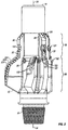
- Figure 1 shows an oblique view of one example of a reaming tool.
- Figure 2 shows a side view of the example reaming tool shown in Figure 1.
- Figure 3 shows an end view of a reaming section of the example reaming tool of Figure 1.
-
- One example of a reaming tool is shown in Figure 1 at 10. The
reaming tool 10 is formed on abody 12 made of high-strength material. Thebody 12 is adapted to be coupled to a rotary wellbore drill string (not shown), preferably by means of threadedconnections body 12. Thebody 12 includes a plurality of azimuthally spaced apartblades 22 formed therein or otherwise affixed to thebody 12. Some of theblades 22 includecutters cutters reaming tool 10 includes a plurality of dullingfluid discharge orifices 26 to provide drilling fluid flow during drilling operations to cool thereaming tool 10 and to wash away drill cuttings as earth formations (not shown) are deformed by thecutters - Generally speaking, the
reaming tool 10 can be divided into a pilothole conditioning section 18 and areaming section 20 each of which will be explained in more detail. One purpose of thehole conditioning section 18 is to provide a round, smooth borehole which acts as a thrust surface against which thecutters 224 in thereaming section 20 can push, so that thereaming section 20 drills a hole having a diameter (referred to as the "drill diameter") which is larger than the diameter of an opening through which thereaming tool 10 can freely pass (this diameter referred to as the "pass-through diameter"). These diameters will be further explained. Another purpose of the pilothole conditioning section 18 is to provide lateral force which balances the lateral forces exerted by thecutters 224 on thereaming section 20, as will he further explained. - A side view of the
example reaming tool 10 is shown in Figure 2. Theblades 22 in the pilothole conditioning section 18 each include on their "downhole" ends (ends nearest threaded connection 14) ataper 28. Threadedconnection 14 is referred to as the downhole end since it is in the direction of a pilot bit (not shown) which can be directly attached to threadedconnection 14 or can be indirectly attached thereto. The pilot bit (not shown) as is understood by those skilled in the art, drills a "pilot" hole having a nominal diameter less than the drill diameter of the reamingtool 10. See for example, T. M. Warren et al, Simultaneous Drilling and Reaming with Fixed Blade Reamers, paper no. 30474, Society of Petroleum Engineers, Richardson, Texas (1995). Thetapers 28 align the reamingtool 10 with the hole drilled by the pilot bit (not shown). In the case where the pilot bit (not shown) is not attached directly to the reamingtool 10, and is therefore axially separated from the reamingtool 10 by a substantial distance, it is preferable to includeauxiliary cutters 128 on thetapers 28 to facilitate alignment of the reamingtool 10. Including theauxiliary cutters 128 on thetapers 28 enables easy passage of the reamingtool 10 along the pilot hole when thelongitudinal axis 34 of the reamingtool 10 is not aligned with the pilot hole due to flexure in the drill string between the pilot bit (not shown) and the reamingtool 10. Theauxiliary cutters 128 also enhance the ability of the reamingtool 10 to properly drill through special equipment ("float equipment") used to cement a steel pipe or casing into a wellbore. Prior art reamer wings did not have good ability to drill through such float equipment without some damage to the casing or to the prior art reamer wing. The numbers of, and azimuthal locations of the blades in the pilothole conditioning section 18 are not meant to limit the invention, but as a practical matter, the reamingtool 10 will perform better if the blades are azimuthally distributed around the circumference of the pilothole conditioning section 18 in a way which substantially maintains the axial position of the reamingtool 10 concentrically within the pilot hole. It is clearly within the contemplation of this aspect of the invention, for example, that two pilot hole conditioning blades spaced 180 degrees apart, or three pilot hole conditioning section blades spaced 120 degrees apart azimuthally in the pilothole conditioning section 18 will result in adequate performance of the reamingtool 10. -
Pilot gauge pads 30 in the pilothole conditioning section 18 help to maintain axial alignment of the reamingtoot 10 in the pilot hole. As is known in the art, pilot holes can be enlarged beyond the diameter of the pilot bit (not shown), out of round, rugose, or otherwise not form a smooth cylindrical surface. This is particularly the case when the pilot bit (not shown) is the roller cone type, as is known in the art. One aspect of the invention is the inclusion ofcutters 124 in the pilothole conditioning section 18. The pilot holeconditioning section cutters 124 are positioned to drill a hole having a slightly larger diameter than the nominal diameter of the pilot bit (not shown). For example, if the pilot bit (not shown) has an 8.5 inch (215.9 mm) diameter, thecutters 124 can be laterally positioned along the pilot hole conditioning section blades to drill an intermediate pilot hole having approximately 9 inch (228.6 mm) diameter. The intermediate pilot hole diameter can be maintained byintermediate gauge pads 32 positioned axially "uphole" (away from the pilot bit) from the pilot holeconditioning section cutters 124. The pilot holeconditioning section cutters 124, and theintermediate gauge pads 32, provide a smooth, round, selected diameter thrust surface against which thereaming section 20 can then drill a hole having the selected drill diameter of the reamingtool 10. The example diameters for the pilot hole and intermediate pilot hole are only meant as examples and are not meant to limit this aspect of the invention. - The positions and orientations of the pilot hole
conditioning section cutters 124 on the pilot blades are preferably selected to provide a lateral force which nearly matches in magnitude and offsets in azimuthal direction, a net lateral force exerted by all thecutters 224 on thereaming section 20. Methods for selecting positions and orientations to achieve the desired force balance are known in the art. See for example, T. M. Warren et al, Drag Bit Performance Modeling, paper no. 15617,Society of Petroleum Engineers, Richardson, TX, 1986. - Figure 3 is an end view of the
reaming section 20. In Figure 3, the reaming blades are designated by numerals B1 through B7 to identify them individually. In making the reamingtool 10 according to one aspect of the invention, the outer surfaces of the reaming blades B1-B7 can first be machined such as on a lathe, or otherwise formed, so as to conform to a circle having the drill diameter, which is twice the largest lateral extent RR shown in Figure 3 from thelongitudinal axis 34 of any of the reaming blades B1-B7. The drill diameter of the reamingtool 10 is the diameter to which the drill hole will be opened by passage of the reamer blades B1-B7 as the reamingtool 10 rotates about thelongitudinal axis 34. This conformance circle, the so-called "drill circle", is shown in Figure 3 at CD. The drill circle CD is substantially coaxial with thelongitudinal axis 34 of the reamingtool 10, as the reamingtool 10 rotates about thelongitudinal axis 34 during drilling. The reaming blades B1-B7 are, in addition, shaped so that the reamingtool 10 can pass freely through an opening which is smaller than the chill diameter (2 X RR). This diameter is referred to as the "pass through" diameter. A circle showing the opening through which thereaming tool 10 will pass is shown in Figure 3 as the "pas-through circle" CP. To enable passage of the reamingtool 10 through the pass-through circle CP, the outer surfaces of the reaming blades B1-B7, after being formed to fit within the drill circle CD, can then be cut such as on a lathe, or otherwise formed, to conform to the pass-through circle CP. The pass-through circle CP, however, is axially offset from the drill circle CD (and the longitudinal axis 34) by an amount which results in some overlap between the circumferences of the pass through circle CP and circumference of the drill circle CD. The intersections of the pass-through circle CP and drill circle CD circumferences are shown at A and B in Figure 3, and the overlapping section ("overlap section") is shown at X. Within the overlap section X, circumferentially between points A and B, any reaming blades so azimuthally located are shaped to conform to the drill circle CD, as within the overlap section X, the drill circle CD is radially less extensive from thelongitudinal axis 34 than is the pass through circle CP. In this example, blades B1 and B2 are located azimuthally within the overlap section X. Outside the overlap section X, the reaming blades (B3-B7 in this example) conform to the pass-through circle CP because within this azimuthal range the pass through circle CP is radially less extensive from thelongitudinal axis 34 than is the drill circle CD. The particular azimuthal locations of the reaming blades B1-B7 shown in Figure 3 are only meant to illustrate the principle by which the reaming blades on the reamingtool 10 are formed. The specific azimuthal positions of the reamer blades, and the numbers of such reamer blades within and without the overlap section X shown in Figure 3 are not meant to specifically limit the invention. - Because the reaming blades B1, B2 within the overlap section X conform to the drill circle CD, the radially
outermost cutters 224A positioned on these blades B1, B2 can then be positioned on the leading edge (the edge of the blade which faces the direction of rotation of the reaming tool 10) thereof so that the cutter locations will trace a circle having the full drill diameter (2 X RR) when the reamingtool 10 rotates about thelongitudinal axis 34. The radially most extensive reaming blades B1, B2, however, are positioned azimuthally in the overlap section X, as previously explained. The drill circle CD defines, with respect to thelongitudinal axis 34, the laterally outermost part of the reamingtool 10 at every azimuthal position, as previously explained. Therefore the blades B1, B2 within the overlap section X will extend only as far laterally as the radius of the drill circle CD. The radiallyoutermost cutters 224A on blades B1 and B2 can be positioned at "full gauge", meaning that thesecutters 224A are at the same radial distance from thelongitudinal axis 34 as the outermost parts of the blade B1, B2 onto which they are attached, and will therefore cut a full drill diameter hole. However, thecutters 224A on blades B1, B2 are also disposed radially inward from the pass-through circle CP at these same azimuthal positions because of the limitation of the lateral extent of these blades B1, B2. Therefore, theoutermost cutters 224A will not contact the inner surface of an opening having a diameter about equal to the pass-through diameter as the reamingtool 10 is moved through such an opening. The preferred shape of the radially outermost reaming blades B1, B2 and the position of radiallyoutermost cutters 224A thereon enables the reamingtool 10 to pass freely through a protective casing (not shown) inserted into a wellbore, without sustaining damage to theoutermost cutters 224A, while at the same time drilling a hole which has the full drill diameter (2 X RR). - The reaming blades which do not extend to full drill diameter (referred to as "non-gauge reaming blades"), shown at B3-B7, preferably have their
outermost cutters 224B positioned radially inward, with respect to pass-through circle CP, of the radially outermost portion of each such non-gauge reaming blade B3-B7 to avoid contact with any part of an opening at about the pass-through diameter. This configuration of blades B3-B7 andcutters 224B has proven to be particularly useful in efficiently drilling through equipment (called "float equipment") used to cement in place the previously referred to casing. By positioning thecutters 224B on the non-gauge reaming blades B3-B7 as described herein, damage to thesecutters 224B can be avoided. Damage to the casing (not shown) can be also be avoided by arranging thenon-gauge cutters 224B as described, particularly when drilling out the float equipment. Although the non-gauge reaming blades B3-B7 are described herein as being formed by causing these blades to conform to the pass-through circle CP, it should be understood that the pass-through circle only represents a radial extension limit for the non-gauge reaming blades B3-B7. It is possible to build the reamingtool 10 with radially shorter non-gauge reaming blades. However, it should also be noted that by having several azimuthally spaced apart non-gauge reaming blades which conform to the pass-through circle CP, the likelihood is reduced that theoutermost cutters 224A on the gauge reaming blades B1, B2 will contact any portion of an opening, such as a well casing, having less than the drill diameter. - Another aspect of the invention is the use of
cutters 224B positioned on the reaming blades B3-B7 located outside the overlap section X. Prior art reamer wings typically had blades substantially only on one side of the reamer. Any lateral extensions of prior art reamer wings in azimuthal positions away from the intended cutting area were typically in the form of pads having no cutting structures thereon. In this aspect of the invention, at least one cutter can be included on each reaming blade B3-B7 located outside the overlap section, even those reaming blades (such as B4-B6 in Figure 3) which are azimuthally substantially opposite the gauge reaming blades B1, B2. The azimuthal positions of the blades B1-B7 shown in Figure 3 are only an example of azimuthal positions which will work with this aspect of the invention, but this aspect of the invention will perform better when the blades B1-B7 are distributed around substantially all the circumference of thebody 12. Preferably thecutters 224B on the non-gauge reaming blades B3-B7, as previously explained, should be located radially inboard of the outer edge of the non-gauge reaming blades to avoid damage thereto when the reamingtool 10 is passed through an opening having the pass through diameter. The purpose of including thecutters 224B on the non-gauge reaming blades B3-B7 is to provide azimuthally more balanced cutting force to the reamingtool 10 than is possible using only cutters on the gauge reaming blades B1, B2. By better azimuthally balancing the cutting forces, the drilling stability of the reamingtool 10 of this invention is improved over prior art reamer wings. The particular positions and/or orientations of thecutters reaming section 20. Methods for selecting cutter orientations and positions are described in the Warren et al reference referred to earlier, for example. - Even using the
cutters 224B on azimuthally distributed blades as shown in Figure 3, thereaming section 20 will develop some net lateral force during drilling of earth formations. The net lateral force is a result of having a much larger number ofcutters 224 concentrated on the gauge reaming blades B1, B2. In an aspect of the invention previously referred to, the positions and/or orientations of the intermediate gauge cutters (124 in Figure 2) on the pilot hole conditioning section (18 in Figure 2) are be selected to provide a net lateral force imbalance which within about twenty percent of axial force (referred to in the art as "weight on bit") applied to the reamingtool 10. More preferably, the net lateral force should be within about fifteen percent of the axial force on the reamingtool 10. Such force balancing enhances the drilling stability of the reamingtool 10 as compared to prior art reamer wings. - Another aspect of the invention is the shape of the reaming blades B1-B7. The preferred shape is spiral-like. No particular configuration of spiral is required, however it is preferred that the blades B1-B7 are shaped so that the
cutters - The reaming blades which do not extend to full drill diameter, B3-B7 in Figure 2, preferably include
inserts 122 on their laterally outermost surfaces. Theinserts 122 can be made from polycrystalline diamond, tungsten carbide, or other hard, wear resistant material. Theinserts 122 reduce wear on the surfaces of the reaming blades B3-B7, particularly when the reamingtool 10 is moved through casing or any other opening having approximately the pass-through diameter. - Referring once again to Figure 2, another aspect of the invention will be explained. At least some of the
blades 22 in thereaming section 20 can be formed into the same structure as the corresponding one of the blades in the pilothole conditioning section 18. Some of thereaming section 20 blades may not be formed as continuations of a corresponding pilot hole conditioning section blade, depending on the number of and azimuthal positions of the blades in the pilothole conditioning section 18. - It will be apparent to those skilled in the art that other embodiment of the invention described herein can be devised which do not depart from the spirit of this invention. Accordingly, the invention shall be limited in scope only by the attached claims.
Claims (16)
- A reaming tool, comprising:a body (12) having reaming blades (B1,...B7) affixed thereto at azimuthally spaced apart locations, selected ones of said reaming blades (B1,...B7) having cutters (224) attached thereto at selected positions, an outermost surface of each of said reaming blades (B1,...B7) conforming to a radially least extensive one with respect to a longitudinal axis (34) of said reaming tool of a pass through circle (CP) and a drill circle (CD), said drill circle (CD) substantially coaxial with said longitudinal axis (34) said pass-through circle (CP) axially offset from said drill circle (CD) and defining an arcuate section (X) wherein said pass-through circle (CP) extends from said longitudinal axis (34) past said drill circle (CD), so that radially outermost cutters (224A) disposed on ones of said reaming blades (B1,B2) positioned azimuthally within said arcuate section (X) drill a hole having a drill diameter substantially twice a maximum lateral extension (RR) of said reaming blades from said longitudinal axis (34) while substantially avoiding wall contact along an opening having a diameter of said pass through circle.
- The reaming tool as defined in claim 1, further comprising:a pilot hole conditioning section (18) comprising a plurality of azimuthally spaced apart pilot blades (22) affixed to said body (12) longitudinally ahead of said reaming blades (B1,...B7), said pilot blades (22) each including a taper (28) at a downhole end thereof, said pilot blades (22) each including a gauge pad (30) having a diameter substantially equal to a drill diameter of a pilot bit used to drill a pilot hole longitudinally ahead of said reaming tool, at least one intermediate cutter (124) affixed to selected ones of said pilot blades (22) longitudinally behind said gauge pad (30), said at least one intermediate cutter (124) laterally positioned to drill a hole having an intermediate diameter larger than said pilot hole and smaller than a drill diameter of said reaming tool, selected ones of said pilot blades (22) including an intermediate gauge pad (32) having a diameter substantially equal to said intermediate diameter.
- A reaming tool, comprising:a body (12) having reaming blades (B1,...B7) affixed thereto at azimuthally spaced apart locations, selected ones of said reaming blades having cutters (224) attached thereto at selected positions thereon; anda pilot hole conditioning section (18) comprising a plurality of azimuthally spaced apart blades (22) affixed to said body (12), said pilot blades (22) each including a taper (28) at a downhole end thereof, said pilot blades (22) each including a gauge pad (30) having a diameter substantially equal to a drill diameter of a pilot bit used to drill a pilot hole longitudinally ahead of said reaming tool, selected ones of said pilot blades (22) including at least one intermediate cutter (124) affixed thereto longitudinally behind said gauge pad (30), said at least one intermediate cutter (124) positioned laterally to drill a hole having an intermediate diameter larger than said pilot hole and smaller that a drill diameter of said reaming tool, selected ones of said pilot blades including an intermediate gauge pad (32) having a diameter substantially equal to said intermediate diameter.
- A reaming tool, comprising:a body (12) having reaming blades (B1,...B7) affixed thereto at azimuthally spaced apart locations around a circumference of said body (18), selected ones of said reaming blades (B1,...B7) including cutters (224) thereon at selected positions; anda pilot hole conditioning section (18) comprising a plurality of azimuthally spaced apart pilot blades (22) affixed to said body (18) longitudinally ahead of said reaming blades (B1,...B7).
- The reaming tool according to claim 4, wherein said at least one cutter (224) is attached to said body (18) at positions and orientations on each of said blades to minimize a net lateral force developed by said reaming tool.
- The reaming tool according to claim 4 or 5, wherein at least one of said reaming blades (B1,...B7) is formed as a single structure with a corresponding one of said pilot blades (22).
- The reaming tool as defined in one of claims 4 to 6, wherein said pilot blades (22) each include a taper (28) at a downhole end thereof, said pilot blades (22) each including a gauge pad (30) having a diameter substantially equal to a drill diameter of a pilot bit used to drill a pilot hole longitudinally ahead of said reaming tool, at least one intermediate cutter (124) affixed to selected ones of said pilot blades (22) longitudinally behind said gauge pad (30), said at least one intermediate cutter (124) laterally positioned to drill a hole having an intermediate diameter larger than said pilot hole and smaller than a drill diameter of said reaming tool, and an intermediate gauge pad (32) having a diameter substantially equal to said intermediate diameter.
- The reaming tool according to one of claims 3 to 7, wherein an outermost surface of each of said reaming blades (B1,...B7) conforms to a radially least extensive one with respect to a longitudinal axis (34) of said reaming tool of a pass through circle (CP) and a drill circle (CD), said drill circle (CD) substantially coaxial with said longitudinal axis (34), said pass-through circle (CP) axially offset from said drill circle (CD) and defining an arcuate section (X) wherein said pass-through circle (CP) extends from said longitudinal axis (34) past said drill circle (CD), so that radially outermost cutters (B1,B2) disposed on ones of said reaming blades disposed within said arcuate section (X) drill a hole having a drill diameter substantially twice a maximum lateral extension (RR) of said reaming blades (B1,...B7) from said longitudinal axis (34) while substantially avoiding wall contact along an opening having a diameter of said pass through circle.
- The reaming tool according to one of claims 1 to 8, wherein at least one of a position and an orientation of said at least one intermediate cutter (124) is selected so that said reaming tool generates a net lateral force less than about twenty percent of an axial force applied to said reaming tool.
- The reaming tool according to one of claims 1 to 8, wherein at least one of a position and an orientation of said at least one intermediate cutter (124) is selected so that said reaming tool generates a net lateral force less that about fifteen percent of an axial force applied to said reaming tool.
- The reaming tool according to one of claims 1 to 10, further comprising an auxiliary cutter (128) disposed on selected ones of said tapers (28) on said pilot blades (22) to improve drill out of float equipment.
- The reaming tool according to one of claims 1 to 11, wherein selected ones of said blades (22) on said pilot hole conditioning section (18) form unitized structures with azimuthally corresponding ones of said reaming blades (B1,...B7).
- The reaming tool according to one of claims 1 to 12, wherein said reaming blades (B1,...B7) are azimuthally distributed around a circumference of said body (12), and further comprising cutters (224) disposed on selected ones of said reaming blades (B1,...B7) in positions and orientations selected to minimize a net lateral force developed by said reaming blades during drilling of earth formations.
- The reaming tool as defined in one of claims 1 to 13, wherein selected ones of said reaming blades (B1,...B7) comprise a spiral structure.
- The reaming tool as defined in one of claims 1 to 14, wherein ones of said reaming blades (B1,B2) disposed azimuthally outside said arcuate section (X) comprise wear resistant inserts (224B) on laterally outermost surfaces thereof.
- The reaming tool as defined in one of claims 1 to 15, wherein selected ones of said blades (22) on said pilot hole conditioning section (18) form unitized structures with azimuthally corresponding ones of said reaming blades (B1,...B7).
Applications Claiming Priority (2)
| Application Number | Priority Date | Filing Date | Title |
|---|---|---|---|
| US09/392,920 US6386302B1 (en) | 1999-09-09 | 1999-09-09 | Polycrystaline diamond compact insert reaming tool |
| US392920 | 1999-09-09 |
Publications (3)
| Publication Number | Publication Date |
|---|---|
| EP1085167A2 true EP1085167A2 (en) | 2001-03-21 |
| EP1085167A3 EP1085167A3 (en) | 2001-06-27 |
| EP1085167B1 EP1085167B1 (en) | 2005-11-23 |
Family
ID=23552558
Family Applications (1)
| Application Number | Title | Priority Date | Filing Date |
|---|---|---|---|
| EP00119792A Expired - Lifetime EP1085167B1 (en) | 1999-09-09 | 2000-09-11 | Polycrystaline diamond compact insert reaming tool |
Country Status (2)
| Country | Link |
|---|---|
| US (4) | US6386302B1 (en) |
| EP (1) | EP1085167B1 (en) |
Cited By (8)
| Publication number | Priority date | Publication date | Assignee | Title |
|---|---|---|---|---|
| BE1014166A5 (en) * | 1999-09-09 | 2003-06-03 | Baker Hughes Inc | BORING DEVICE FOR REFORMING CEMENT AND FLOATING EQUIPMENT IN TUBING. |
| BE1015740A3 (en) * | 2002-04-10 | 2005-08-02 | Baker Hughes Inc | |
| EP1818501A3 (en) * | 2001-08-08 | 2007-09-26 | SMITH INTERNATIONAL, INC. (a Delaware corp.) | Advanced expandable reaming tool |
| US8042625B2 (en) | 2008-11-03 | 2011-10-25 | National Oilwell Varco, L.P. | Drilling tool |
| US9534448B2 (en) | 2013-10-31 | 2017-01-03 | Halliburton Energy Services, Inc. | Unbalance force identifiers and balancing methods for drilling equipment assemblies |
| WO2018152022A1 (en) * | 2017-02-15 | 2018-08-23 | National Oilwell Varco, L.P. | Bi-center bit and drilling tools with enhanced hydraulics |
| EP1785580B1 (en) * | 2005-10-19 | 2021-01-06 | Max Streicher GmbH & Co. Kommanditgesellschaft auf Aktien | Process for laying pipes, reamer, boring machine and pipe |
| CN114472961A (en) * | 2022-01-29 | 2022-05-13 | 王力安防科技股份有限公司 | Lock head hole reaming positioner and have reaming device of this locator |
Families Citing this family (74)
| Publication number | Priority date | Publication date | Assignee | Title |
|---|---|---|---|---|
| US6386302B1 (en) * | 1999-09-09 | 2002-05-14 | Smith International, Inc. | Polycrystaline diamond compact insert reaming tool |
| US6739416B2 (en) | 2002-03-13 | 2004-05-25 | Baker Hughes Incorporated | Enhanced offset stabilization for eccentric reamers |
| US7036611B2 (en) | 2002-07-30 | 2006-05-02 | Baker Hughes Incorporated | Expandable reamer apparatus for enlarging boreholes while drilling and methods of use |
| US6913098B2 (en) * | 2002-11-21 | 2005-07-05 | Reedeycalog, L.P. | Sub-reamer for bi-center type tools |
| US8185365B2 (en) * | 2003-03-26 | 2012-05-22 | Smith International, Inc. | Radial force distributions in rock bits |
| US6926099B2 (en) * | 2003-03-26 | 2005-08-09 | Varel International, L.P. | Drill out bi-center bit and method for using same |
| US6904984B1 (en) | 2003-06-20 | 2005-06-14 | Rock Bit L.P. | Stepped polycrystalline diamond compact insert |
| US7152702B1 (en) * | 2005-11-04 | 2006-12-26 | Smith International, Inc. | Modular system for a back reamer and method |
| WO2008076117A1 (en) * | 2006-12-21 | 2008-06-26 | Smith International, Inc. | Modular system for a back reamer |
| US8177000B2 (en) * | 2006-12-21 | 2012-05-15 | Sandvik Intellectual Property Ab | Modular system for a back reamer and method |
| US7841426B2 (en) * | 2007-04-05 | 2010-11-30 | Baker Hughes Incorporated | Hybrid drill bit with fixed cutters as the sole cutting elements in the axial center of the drill bit |
| US7845435B2 (en) | 2007-04-05 | 2010-12-07 | Baker Hughes Incorporated | Hybrid drill bit and method of drilling |
| US20080251293A1 (en) * | 2007-04-12 | 2008-10-16 | Ulterra Drilling Technologies, L.L.C. | Circumvolve cutters for drill bit |
| US8678111B2 (en) * | 2007-11-16 | 2014-03-25 | Baker Hughes Incorporated | Hybrid drill bit and design method |
| SA108290832B1 (en) | 2007-12-21 | 2012-06-05 | بيكر هوغيس انكوربوريتد | Reamer with Stabilizer Arms for Use in A Wellbore |
| SA108290829B1 (en) * | 2007-12-21 | 2012-01-24 | بيكر هوغيس انكوربوريتد | Reamer with Balanced Cutting Structure for Use in A Wellbore |
| US7938204B2 (en) * | 2007-12-21 | 2011-05-10 | Baker Hughes Incorporated | Reamer with improved hydraulics for use in a wellbore |
| US20090272582A1 (en) | 2008-05-02 | 2009-11-05 | Baker Hughes Incorporated | Modular hybrid drill bit |
| US8025107B2 (en) * | 2008-05-15 | 2011-09-27 | Longyear Tm, Inc. | Reamer with polycrystalline diamond compact inserts |
| US7819208B2 (en) | 2008-07-25 | 2010-10-26 | Baker Hughes Incorporated | Dynamically stable hybrid drill bit |
| US8162081B2 (en) * | 2008-08-28 | 2012-04-24 | Varel International Ind., L.P. | Force balanced asymmetric drilling reamer and methods for force balancing |
| GB0818493D0 (en) * | 2008-10-09 | 2008-11-19 | Reedhycalog Uk Ltd | Drilling tool |
| US8450637B2 (en) | 2008-10-23 | 2013-05-28 | Baker Hughes Incorporated | Apparatus for automated application of hardfacing material to drill bits |
| US9439277B2 (en) | 2008-10-23 | 2016-09-06 | Baker Hughes Incorporated | Robotically applied hardfacing with pre-heat |
| US20100101864A1 (en) * | 2008-10-27 | 2010-04-29 | Olivier Sindt | Anti-whirl drill bits, wellsite systems, and methods of using the same |
| US20100101867A1 (en) * | 2008-10-27 | 2010-04-29 | Olivier Sindt | Self-stabilized and anti-whirl drill bits and bottom-hole assemblies and systems for using the same |
| WO2010053710A2 (en) | 2008-10-29 | 2010-05-14 | Baker Hughes Incorporated | Method and apparatus for robotic welding of drill bits |
| US7992658B2 (en) * | 2008-11-11 | 2011-08-09 | Baker Hughes Incorporated | Pilot reamer with composite framework |
| US20100122848A1 (en) * | 2008-11-20 | 2010-05-20 | Baker Hughes Incorporated | Hybrid drill bit |
| CA2745812C (en) | 2008-12-11 | 2019-05-14 | Halliburton Energy Services, Inc. | Multilevel force balanced downhole drilling tools and methods |
| US8047307B2 (en) | 2008-12-19 | 2011-11-01 | Baker Hughes Incorporated | Hybrid drill bit with secondary backup cutters positioned with high side rake angles |
| US20100155146A1 (en) * | 2008-12-19 | 2010-06-24 | Baker Hughes Incorporated | Hybrid drill bit with high pilot-to-journal diameter ratio |
| MX2011006187A (en) | 2008-12-31 | 2011-06-20 | Baker Hughes Inc | Method and apparatus for automated application of hardfacing material to rolling cutters of hybrid-type earth boring drill bits, hybrid drill bits comprising such hardfaced steel-toothed cutting elements, and methods of use thereof. |
| US20100181116A1 (en) * | 2009-01-16 | 2010-07-22 | Baker Hughes Incororated | Impregnated drill bit with diamond pins |
| US8141664B2 (en) | 2009-03-03 | 2012-03-27 | Baker Hughes Incorporated | Hybrid drill bit with high bearing pin angles |
| US20100252325A1 (en) * | 2009-04-02 | 2010-10-07 | National Oilwell Varco | Methods for determining mechanical specific energy for wellbore operations |
| US8887836B2 (en) * | 2009-04-15 | 2014-11-18 | Baker Hughes Incorporated | Drilling systems for cleaning wellbores, bits for wellbore cleaning, methods of forming such bits, and methods of cleaning wellbores using such bits |
| US8056651B2 (en) | 2009-04-28 | 2011-11-15 | Baker Hughes Incorporated | Adaptive control concept for hybrid PDC/roller cone bits |
| US8459378B2 (en) | 2009-05-13 | 2013-06-11 | Baker Hughes Incorporated | Hybrid drill bit |
| US8157026B2 (en) | 2009-06-18 | 2012-04-17 | Baker Hughes Incorporated | Hybrid bit with variable exposure |
| WO2011035051A2 (en) | 2009-09-16 | 2011-03-24 | Baker Hughes Incorporated | External, divorced pdc bearing assemblies for hybrid drill bits |
| US8448724B2 (en) | 2009-10-06 | 2013-05-28 | Baker Hughes Incorporated | Hole opener with hybrid reaming section |
| US8191635B2 (en) | 2009-10-06 | 2012-06-05 | Baker Hughes Incorporated | Hole opener with hybrid reaming section |
| US20110240378A1 (en) * | 2010-04-01 | 2011-10-06 | Hall David R | Tapered Blade Profile on an Outer Bit |
| SA114350454B1 (en) | 2010-06-29 | 2015-12-20 | بيكر هوغيس انكوربوريتد | Drill bits with anti-tracking feature |
| US8978786B2 (en) | 2010-11-04 | 2015-03-17 | Baker Hughes Incorporated | System and method for adjusting roller cone profile on hybrid bit |
| CA2826685C (en) | 2011-02-11 | 2016-03-29 | Baker Hughes Incorporated | System and method for leg retention on hybrid bits |
| US9782857B2 (en) | 2011-02-11 | 2017-10-10 | Baker Hughes Incorporated | Hybrid drill bit having increased service life |
| US8851205B1 (en) * | 2011-04-08 | 2014-10-07 | Hard Rock Solutions, Llc | Method and apparatus for reaming well bore surfaces nearer the center of drift |
| CA2850795C (en) * | 2011-10-03 | 2016-08-16 | Gilbert T. Meier | Wellbore conditioning system |
| EP3159475B1 (en) | 2011-11-15 | 2019-03-27 | Baker Hughes, a GE company, LLC | Hybrid drill bits having increased drilling efficiency |
| WO2013101925A2 (en) * | 2011-12-27 | 2013-07-04 | National Oilwell DHT, L.P. | Downhole cutting tool |
| US9493991B2 (en) | 2012-04-02 | 2016-11-15 | Baker Hughes Incorporated | Cutting structures, tools for use in subterranean boreholes including cutting structures and related methods |
| WO2015099718A1 (en) | 2013-12-26 | 2015-07-02 | Halliburton Energy Services, Inc. | Multilevel force balanced downhole drilling tools including cutting elements in a step profile configuration |
| GB2536821B (en) | 2013-12-26 | 2018-04-18 | Halliburton Energy Services Inc | Multilevel force balanced downhole drilling tools including cutting elements in a track-set configuration |
| BR112016027337A8 (en) | 2014-05-23 | 2021-05-04 | Baker Hughes Inc | hybrid drill with mechanically fixed cutter assembly |
| BE1023426B1 (en) * | 2014-05-30 | 2017-03-15 | Diarotech S.A. | STABILIZER-ALESEUR FOR DRILLING TRAIN |
| GB2535787B (en) | 2015-02-27 | 2017-08-16 | Schlumberger Holdings | Milling tool and method |
| US11428050B2 (en) | 2014-10-20 | 2022-08-30 | Baker Hughes Holdings Llc | Reverse circulation hybrid bit |
| US10472934B2 (en) | 2015-05-21 | 2019-11-12 | Novatek Ip, Llc | Downhole transducer assembly |
| US10113399B2 (en) | 2015-05-21 | 2018-10-30 | Novatek Ip, Llc | Downhole turbine assembly |
| GB2539005B (en) | 2015-06-03 | 2017-12-27 | Schlumberger Holdings | Rotary cutting tool with angled flow channel on outward face |
| US10557311B2 (en) | 2015-07-17 | 2020-02-11 | Halliburton Energy Services, Inc. | Hybrid drill bit with counter-rotation cutters in center |
| GB2546518A (en) | 2016-01-21 | 2017-07-26 | Schlumberger Holdings | Rotary cutting tools |
| CN110073073B (en) | 2016-11-15 | 2022-11-15 | 斯伦贝谢技术有限公司 | System and method for directing fluid flow |
| US10439474B2 (en) * | 2016-11-16 | 2019-10-08 | Schlumberger Technology Corporation | Turbines and methods of generating electricity |
| CN110678622B (en) * | 2017-05-05 | 2021-12-21 | 史密斯国际有限公司 | Stepped downhole tool and method of use |
| US11111739B2 (en) | 2017-09-09 | 2021-09-07 | Extreme Technologies, Llc | Well bore conditioner and stabilizer |
| AU2018347352B2 (en) | 2017-10-10 | 2024-02-15 | Extreme Technologies, Llc | Wellbore reaming systems and devices |
| WO2019147820A1 (en) | 2018-01-24 | 2019-08-01 | Stabil Drill Specialties, L.L.C. | Eccentric reaming tool |
| US10597947B2 (en) | 2018-05-18 | 2020-03-24 | Baker Hughes, A Ge Company, Llc | Reamers for earth-boring applications having increased stability and related methods |
| CA3189357A1 (en) * | 2020-07-15 | 2022-01-20 | Shear Bits, Inc. | Wellbore reaming tool having fixed mounted gouging cutters |
| US11441360B2 (en) | 2020-12-17 | 2022-09-13 | National Oilwell Varco, L.P. | Downhole eccentric reamer tool and related systems and methods |
| CN117345115B (en) * | 2023-12-04 | 2024-03-15 | 中国石油大学(华东) | Drill bit with strong track control capability and high drilling efficiency under action of pushing force |
Citations (3)
| Publication number | Priority date | Publication date | Assignee | Title |
|---|---|---|---|---|
| US5495899A (en) | 1995-04-28 | 1996-03-05 | Baker Hughes Incorporated | Reamer wing with balanced cutting loads |
| US5497842A (en) | 1995-04-28 | 1996-03-12 | Baker Hughes Incorporated | Reamer wing for enlarging a borehole below a smaller-diameter portion therof |
| US5765653A (en) | 1996-10-09 | 1998-06-16 | Baker Hughes Incorporated | Reaming apparatus and method with enhanced stability and transition from pilot hole to enlarged bore diameter |
Family Cites Families (34)
| Publication number | Priority date | Publication date | Assignee | Title |
|---|---|---|---|---|
| US1754830A (en) | 1926-11-20 | 1930-04-15 | John W Macclatchie | Underreamer |
| US1844371A (en) * | 1930-02-24 | 1932-02-09 | Grant John | Hole reaming and straightening device |
| US3237705A (en) * | 1963-11-13 | 1966-03-01 | Williams Joseph W | Reamer for enlarging and straightening bore holes |
| US3367430A (en) | 1966-08-24 | 1968-02-06 | Christensen Diamond Prod Co | Combination drill and reamer bit |
| US3420323A (en) * | 1967-02-23 | 1969-01-07 | Land & Marine Rental Co | Drill stabilizer tool |
| US3851719A (en) * | 1973-03-22 | 1974-12-03 | American Coldset Corp | Stabilized under-drilling apparatus |
| US4031974A (en) * | 1975-05-27 | 1977-06-28 | Rapidex, Inc. | Boring apparatus capable of boring straight holes |
| US4190124A (en) * | 1978-10-23 | 1980-02-26 | Thomas L. Taylor | Stabilizer and blade attachment means therefor |
| NO820347L (en) | 1981-02-07 | 1982-08-09 | Drilling & Service Uk Ltd | BACKGROUND TOOLS TOOL |
| US4449595A (en) * | 1982-05-17 | 1984-05-22 | Holbert Don R | Method and apparatus for drilling a curved bore |
| US4515227A (en) * | 1983-04-27 | 1985-05-07 | Christensen, Inc. | Nozzle placement in a diamond rotating bit including a pilot bit |
| US4630694A (en) * | 1985-10-16 | 1986-12-23 | Walton Paul G | Integral blade hole opener |
| US4618010A (en) * | 1986-02-18 | 1986-10-21 | Team Engineering And Manufacturing, Inc. | Hole opener |
| US4793719A (en) * | 1987-11-18 | 1988-12-27 | Smith International, Inc. | Precision roller bearing rock bits |
| US4822057A (en) * | 1988-03-31 | 1989-04-18 | Smith International, Inc. | Mechanical face seal for rock bits |
| NO178938C (en) * | 1992-04-30 | 1996-07-03 | Geir Tandberg | Borehole expansion device |
| GB9211946D0 (en) | 1992-06-05 | 1992-07-15 | Panther Oil Tools Uk Ltd | Backreaming stabilizer |
| US5423389A (en) | 1994-03-25 | 1995-06-13 | Amoco Corporation | Curved drilling apparatus |
| US5726969A (en) * | 1994-12-28 | 1998-03-10 | Matsushita Electric Industrial Co., Ltd. | Optical recording medium having dual information surfaces |
| USRE36817E (en) | 1995-04-28 | 2000-08-15 | Baker Hughes Incorporated | Method and apparatus for drilling and enlarging a borehole |
| US5678644A (en) * | 1995-08-15 | 1997-10-21 | Diamond Products International, Inc. | Bi-center and bit method for enhancing stability |
| US5992548A (en) | 1995-08-15 | 1999-11-30 | Diamond Products International, Inc. | Bi-center bit with oppositely disposed cutting surfaces |
| CN1102793C (en) * | 1995-12-07 | 2003-03-05 | 松下电器产业株式会社 | Magnetic tape recording and/or reproduction apparatus and its reel braking mechanism |
| US5957223A (en) * | 1997-03-05 | 1999-09-28 | Baker Hughes Incorporated | Bi-center drill bit with enhanced stabilizing features |
| US6039131A (en) * | 1997-08-25 | 2000-03-21 | Smith International, Inc. | Directional drift and drill PDC drill bit |
| US6213226B1 (en) * | 1997-12-04 | 2001-04-10 | Halliburton Energy Services, Inc. | Directional drilling assembly and method |
| US6213229B1 (en) * | 1998-10-13 | 2001-04-10 | Smith International Canada Limited | Drilling motor drill bit reaming stabilizer |
| US6269893B1 (en) * | 1999-06-30 | 2001-08-07 | Smith International, Inc. | Bi-centered drill bit having improved drilling stability mud hydraulics and resistance to cutter damage |
| US6695080B2 (en) * | 1999-09-09 | 2004-02-24 | Baker Hughes Incorporated | Reaming apparatus and method with enhanced structural protection |
| US6386302B1 (en) * | 1999-09-09 | 2002-05-14 | Smith International, Inc. | Polycrystaline diamond compact insert reaming tool |
| US6397958B1 (en) * | 1999-09-09 | 2002-06-04 | Baker Hughes Incorporated | Reaming apparatus and method with ability to drill out cement and float equipment in casing |
| US6394200B1 (en) * | 1999-10-28 | 2002-05-28 | Camco International (U.K.) Limited | Drillout bi-center bit |
| US6853660B2 (en) * | 2002-10-16 | 2005-02-08 | Eastman Kodak Company | Organic laser cavity arrays |
| US6926099B2 (en) * | 2003-03-26 | 2005-08-09 | Varel International, L.P. | Drill out bi-center bit and method for using same |
-
1999
- 1999-09-09 US US09/392,920 patent/US6386302B1/en not_active Expired - Lifetime
-
2000
- 2000-09-11 EP EP00119792A patent/EP1085167B1/en not_active Expired - Lifetime
-
2002
- 2002-05-08 US US10/141,448 patent/US6609580B2/en not_active Expired - Lifetime
-
2003
- 2003-08-04 US US10/633,796 patent/US7137463B2/en not_active Expired - Fee Related
-
2006
- 2006-10-10 US US11/545,277 patent/US7293617B2/en not_active Expired - Fee Related
Patent Citations (3)
| Publication number | Priority date | Publication date | Assignee | Title |
|---|---|---|---|---|
| US5495899A (en) | 1995-04-28 | 1996-03-05 | Baker Hughes Incorporated | Reamer wing with balanced cutting loads |
| US5497842A (en) | 1995-04-28 | 1996-03-12 | Baker Hughes Incorporated | Reamer wing for enlarging a borehole below a smaller-diameter portion therof |
| US5765653A (en) | 1996-10-09 | 1998-06-16 | Baker Hughes Incorporated | Reaming apparatus and method with enhanced stability and transition from pilot hole to enlarged bore diameter |
Non-Patent Citations (2)
| Title |
|---|
| T.M. WARREN ET AL.: "Simultaneous drilling and reaming with fixed blade reamers", SOCIETY OF PETROLEUM ENGINEERS 1995, no. 30474, RICHARDSON TEXAS |
| T.M. WARREN ET AL: "Drag bit performance modeling", SOCIETY OF PETROLEUM ENGINEERS 1986, no. 15617, RICHARDSON TEXAS |
Cited By (12)
| Publication number | Priority date | Publication date | Assignee | Title |
|---|---|---|---|---|
| BE1014166A5 (en) * | 1999-09-09 | 2003-06-03 | Baker Hughes Inc | BORING DEVICE FOR REFORMING CEMENT AND FLOATING EQUIPMENT IN TUBING. |
| EP1818501A3 (en) * | 2001-08-08 | 2007-09-26 | SMITH INTERNATIONAL, INC. (a Delaware corp.) | Advanced expandable reaming tool |
| US7451836B2 (en) | 2001-08-08 | 2008-11-18 | Smith International, Inc. | Advanced expandable reaming tool |
| US7451837B2 (en) | 2001-08-08 | 2008-11-18 | Smith International, Inc. | Advanced expandable reaming tool |
| BE1015740A3 (en) * | 2002-04-10 | 2005-08-02 | Baker Hughes Inc | |
| EP1785580B1 (en) * | 2005-10-19 | 2021-01-06 | Max Streicher GmbH & Co. Kommanditgesellschaft auf Aktien | Process for laying pipes, reamer, boring machine and pipe |
| US8042625B2 (en) | 2008-11-03 | 2011-10-25 | National Oilwell Varco, L.P. | Drilling tool |
| US9534448B2 (en) | 2013-10-31 | 2017-01-03 | Halliburton Energy Services, Inc. | Unbalance force identifiers and balancing methods for drilling equipment assemblies |
| WO2018152022A1 (en) * | 2017-02-15 | 2018-08-23 | National Oilwell Varco, L.P. | Bi-center bit and drilling tools with enhanced hydraulics |
| US10927608B2 (en) | 2017-02-15 | 2021-02-23 | National Oilwell Varco, L.P. | Bi-center bit and drilling tools with enhanced hydraulics |
| CN114472961A (en) * | 2022-01-29 | 2022-05-13 | 王力安防科技股份有限公司 | Lock head hole reaming positioner and have reaming device of this locator |
| CN114472961B (en) * | 2022-01-29 | 2023-08-08 | 王力安防科技股份有限公司 | Tapered end hole expanding locator and hole expanding device with same |
Also Published As
| Publication number | Publication date |
|---|---|
| EP1085167A3 (en) | 2001-06-27 |
| US20020125047A1 (en) | 2002-09-12 |
| US6386302B1 (en) | 2002-05-14 |
| US6609580B2 (en) | 2003-08-26 |
| US20070029115A1 (en) | 2007-02-08 |
| US20040206552A1 (en) | 2004-10-21 |
| US7137463B2 (en) | 2006-11-21 |
| EP1085167B1 (en) | 2005-11-23 |
| US7293617B2 (en) | 2007-11-13 |
Similar Documents
| Publication | Publication Date | Title |
|---|---|---|
| EP1085167B1 (en) | Polycrystaline diamond compact insert reaming tool | |
| US6269893B1 (en) | Bi-centered drill bit having improved drilling stability mud hydraulics and resistance to cutter damage | |
| US6659207B2 (en) | Bi-centered drill bit having enhanced casing drill-out capability and improved directional stability | |
| CA2427254C (en) | Fixed blade fixed cutter hole opener | |
| US9488009B2 (en) | Apparatuses and methods for stabilizing downhole tools | |
| EP2019901B1 (en) | Reaming tool suitable for running on casing or liner and method of reaming | |
| US7954564B2 (en) | Placement of cutting elements on secondary cutting structures of drilling tool assemblies | |
| US10526849B2 (en) | Cutting structure with blade having multiple cutting edges | |
| GB2438520A (en) | Drill bit | |
| GB2328698A (en) | Drill bit | |
| US20230094335A1 (en) | Eccentric Reaming Tool | |
| WO2015167786A1 (en) | Cutting structure of a downhole cutting tool | |
| EP0347033A2 (en) | Borehole underreamers | |
| US11913286B2 (en) | Earth-boring tools with through-the-blade fluid ports, and related methods | |
| GB2376489A (en) | Bi-centre drill bit | |
| WO2019103911A1 (en) | Earth boring tools having fixed blades, rotatable cutting structures, and stabilizing structures, and related methods | |
| CA2553380A1 (en) | Bi-centered drill bit having improved drilling stability, mud hydraulics and resistance to cutter damage | |
| GB2386630A (en) | Bi-centred drill bit having a reverse-oriented cutting element | |
| CA2545568A1 (en) | Bi-centered drill bit having enhanced casing drill-out capability and improved directional stability |
Legal Events
| Date | Code | Title | Description |
|---|---|---|---|
| PUAI | Public reference made under article 153(3) epc to a published international application that has entered the european phase |
Free format text: ORIGINAL CODE: 0009012 |
|
| 17P | Request for examination filed |
Effective date: 20001113 |
|
| AK | Designated contracting states |
Kind code of ref document: A2 Designated state(s): BE GB |
|
| AX | Request for extension of the european patent |
Free format text: AL;LT;LV;MK;RO;SI |
|
| PUAL | Search report despatched |
Free format text: ORIGINAL CODE: 0009013 |
|
| AK | Designated contracting states |
Kind code of ref document: A3 Designated state(s): AT BE CH CY DE DK ES FI FR GB GR IE IT LI LU MC NL PT SE |
|
| AX | Request for extension of the european patent |
Free format text: AL;LT;LV;MK;RO;SI |
|
| RIC1 | Information provided on ipc code assigned before grant |
Free format text: 7E 21B 10/26 A, 7E 21B 10/42 B |
|
| AKX | Designation fees paid |
Free format text: BE GB |
|
| REG | Reference to a national code |
Ref country code: DE Ref legal event code: 8566 |
|
| 17Q | First examination report despatched |
Effective date: 20040126 |
|
| GRAP | Despatch of communication of intention to grant a patent |
Free format text: ORIGINAL CODE: EPIDOSNIGR1 |
|
| GRAS | Grant fee paid |
Free format text: ORIGINAL CODE: EPIDOSNIGR3 |
|
| GRAA | (expected) grant |
Free format text: ORIGINAL CODE: 0009210 |
|
| AK | Designated contracting states |
Kind code of ref document: B1 Designated state(s): BE GB |
|
| REG | Reference to a national code |
Ref country code: GB Ref legal event code: FG4D |
|
| PLBE | No opposition filed within time limit |
Free format text: ORIGINAL CODE: 0009261 |
|
| STAA | Information on the status of an ep patent application or granted ep patent |
Free format text: STATUS: NO OPPOSITION FILED WITHIN TIME LIMIT |
|
| 26N | No opposition filed |
Effective date: 20060824 |
|
| PGFP | Annual fee paid to national office [announced via postgrant information from national office to epo] |
Ref country code: GB Payment date: 20140903 Year of fee payment: 15 |
|
| PGFP | Annual fee paid to national office [announced via postgrant information from national office to epo] |
Ref country code: BE Payment date: 20140912 Year of fee payment: 15 |
|
| GBPC | Gb: european patent ceased through non-payment of renewal fee |
Effective date: 20150911 |
|
| PG25 | Lapsed in a contracting state [announced via postgrant information from national office to epo] |
Ref country code: GB Free format text: LAPSE BECAUSE OF NON-PAYMENT OF DUE FEES Effective date: 20150911 |
|
| PG25 | Lapsed in a contracting state [announced via postgrant information from national office to epo] |
Ref country code: BE Free format text: LAPSE BECAUSE OF NON-PAYMENT OF DUE FEES Effective date: 20150930 |