EP1081667B1 - Method and apparatus for providing access to an interactive product - Google Patents
Method and apparatus for providing access to an interactive product Download PDFInfo
- Publication number
- EP1081667B1 EP1081667B1 EP00203983A EP00203983A EP1081667B1 EP 1081667 B1 EP1081667 B1 EP 1081667B1 EP 00203983 A EP00203983 A EP 00203983A EP 00203983 A EP00203983 A EP 00203983A EP 1081667 B1 EP1081667 B1 EP 1081667B1
- Authority
- EP
- European Patent Office
- Prior art keywords
- vehicle
- passenger
- interactive product
- moving
- access
- Prior art date
- Legal status (The legal status is an assumption and is not a legal conclusion. Google has not performed a legal analysis and makes no representation as to the accuracy of the status listed.)
- Expired - Lifetime
Links
Images

Classifications
-
- G—PHYSICS
- G01—MEASURING; TESTING
- G01C—MEASURING DISTANCES, LEVELS OR BEARINGS; SURVEYING; NAVIGATION; GYROSCOPIC INSTRUMENTS; PHOTOGRAMMETRY OR VIDEOGRAMMETRY
- G01C21/00—Navigation; Navigational instruments not provided for in groups G01C1/00 - G01C19/00
- G01C21/26—Navigation; Navigational instruments not provided for in groups G01C1/00 - G01C19/00 specially adapted for navigation in a road network
- G01C21/34—Route searching; Route guidance
- G01C21/36—Input/output arrangements for on-board computers
- G01C21/3626—Details of the output of route guidance instructions
- G01C21/3641—Personalized guidance, e.g. limited guidance on previously travelled routes
-
- B—PERFORMING OPERATIONS; TRANSPORTING
- B60—VEHICLES IN GENERAL
- B60K—ARRANGEMENT OR MOUNTING OF PROPULSION UNITS OR OF TRANSMISSIONS IN VEHICLES; ARRANGEMENT OR MOUNTING OF PLURAL DIVERSE PRIME-MOVERS IN VEHICLES; AUXILIARY DRIVES FOR VEHICLES; INSTRUMENTATION OR DASHBOARDS FOR VEHICLES; ARRANGEMENTS IN CONNECTION WITH COOLING, AIR INTAKE, GAS EXHAUST OR FUEL SUPPLY OF PROPULSION UNITS IN VEHICLES
- B60K35/00—Arrangement of adaptations of instruments
-
- G—PHYSICS
- G08—SIGNALLING
- G08G—TRAFFIC CONTROL SYSTEMS
- G08G1/00—Traffic control systems for road vehicles
- G08G1/09—Arrangements for giving variable traffic instructions
- G08G1/0962—Arrangements for giving variable traffic instructions having an indicator mounted inside the vehicle, e.g. giving voice messages
- G08G1/0968—Systems involving transmission of navigation instructions to the vehicle
- G08G1/096805—Systems involving transmission of navigation instructions to the vehicle where the transmitted instructions are used to compute a route
- G08G1/096827—Systems involving transmission of navigation instructions to the vehicle where the transmitted instructions are used to compute a route where the route is computed onboard
Definitions
- the present invention relates to the provision of access to an interactive product, for example, a vehicle navigation system. More specifically, there will be described below, by way of example in illustration of the present invention methods and apparatus for providing passenger access to a vehicle navigation system while the vehicle is moving, without defeating the purpose of "lock out" features intended to control driver access to the system.
- the access device is a button or switch which is provided within the vehicle and which is remote from the system. The device is located so that the passenger has easy access to it. However, its location is such that it is substantially inaccessible to the driver.
- the access device is a button or switch which is integrated into the system in such a way that it is fairly simple for the passenger to use, but difficult or impossible for the driver to use.
- the access device includes a button
- the button must be continuously depressed (i.e., activated) for the system keypad to be used.
- two hands are required to operate the system, making it much more difficult for the driver to use than the passenger.
- the access device is a sensor which senses whether or not a passenger is seated in the passenger seat. If a passenger is in the seat, user interaction with the system is enabled. If not, the "lock out" feature is employed. In another embodiment, the sensor determines not only whether there is a passenger in the seat, but whether the passenger is wearing a seat belt. Such embodiments may make use of existing seat belt sensing electronics.
- the access device is a hand held remote control device by means of which a passenger may interact with the system.
- At least one control device is provided for allowing user interaction with the interactive product. Interaction with the interactive product via the at least one control device is inhibited in the particular method while the vehicle is moving.
- An access device is provided which must be employed in conjunction with the at least one control device to enable user interaction with the interactive product while the vehicle is moving. Interaction with the interactive product via the at least one control device is allowed while the vehicle is moving in response to activation of this access device.
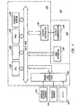
- Fig. 1 is a block diagram of a specific embodiment of a vehicle navigation system 100 for use with the present invention.
- Sensors 112 and 114 and GPS receiver 118 are coupled to computing means 120 through sensor/GPS interface 122.
- mileage sensor 112 comprises an odometer
- angular velocity sensor 114 comprises a gyroscope, or a differential odometer coupled to the wheels of the vehicle.
- a global positioning system (GPS) data receiver 118 is provided for receiving signals from, for example, a satellite-based navigation system. Data from sensor/GPS interface 122 is transmitted to CPU 124, which performs calibration, signal processing, dead-reckoning, vehicle positioning, and route guidance functions.
- GPS global positioning system
- a database containing map information may be stored in database medium 126, with software directing the operation of computing means 120 stored in main memory 128 for execution by CPU 124.
- Memory 128 may comprise read-only memory (ROM), or reprogrammable non-volatile memory such as flash memory or SRAM.
- System RAM 130 permits reading and writing of the information necessary to execute such software programs.
- Database medium 126 may comprise non-volatile memory, a hard disk drive, CD-ROM, or an integrated circuit in which digitized map information has been stored.
- Output controller 132 which may comprise a graphics controller, receives data processed by CPU 124 and transmits the data to display console 140 which includes output communicator 134, usually comprising a display screen with associated audio electronics and audio speakers.
- the driver may input data, such as a desired destination, through user interface 136, typically comprising a keyboard.
- the map database stored in database medium 126 preferably comprises positional data such as, for example, latitude and longitude coordinates, to describe road intersections or nodes, road segments, landmarks and points of interest, and other geographical information.
- the data base may further comprise data representing characteristics of roads or places on the map, such as road and place names, road features such as dividers, one-way restrictions, surface, speed limit, shape, elevation, and other properties.
- the map database includes cost values associated with individual nodes and road segments. These cost values correspond to the estimates of time intervals for traversing the respective node or segment. Node cost values take into consideration such information as, for example, whether the vehicle would encounter oncoming traffic, thus delaying a left turn manoeuvre.
- Segment costs reflect road segment characteristics such as speed limit and segment length, both of which affect the travel time along the segment.
- a link class which relates to the category or type of the road.
- the highest level category of the hierarchy is the link class FREEWAY.
- the lowest level includes the link classes FRONTAGE and MISC which include, for example, frontage roads and alleys.
- a vehicle navigation system for use with the present invention is for example operable to generate a route from a source location to a destination according to a variety of different methods. Some examples of such methods are described in the U.S. patents which have been mentioned above.
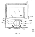
- FIG. 2 is an illustration of a vehicle navigation system display console 200.
- Console 200 has a display screen 202, a power switch 204, and function keys (i.e., control devices) 206-216.
- a scrolling key 206 is centrally located below display screen 202 with two "Quick Scroll” keys 208 adjacent scrolling key 206 to its left and right. Scrolling key 206 controls the position of a cursor on display screen 202 during destination selection. "Quick Scroll” keys 208 both perform the same function which is to increase the speed with which scrolling key 206 scrolls through destination options on display screen 202.
- Enter key 210 allows the user of the vehicle navigation system to enter the destination option currently highlighted by the cursor.
- Cancel key 212 allows the user to cancel the current operation and return to the previous step.
- Route/Map key 214 allows the user to switch between two different route guidance modes.
- Option key 216 allows the user to reconfigure various features of the system set up.
- Display console 200 also includes passenger access key 218 located on the side of console 200 away from the driver. While the vehicle is moving, passenger access key 218 must be activated, i.e., depressed, to enable function keys 206-216. According to specific embodiments, passenger access key must be continuously depressed while function keys 206-216 are used.
- the passenger access device may alternatively be located remotely from console 200 as indicated by the dashed outline 218'. The positioning of remote passenger access key 218' should be such that it is easily used by someone in the passenger seat, but is substantially inaccessible to the driver.
- Fig. 3 is a flowchart 300 illustrating the operation of a specific embodiment of the invention.
- the system determines whether or not the vehicle is moving (step 304). If the vehicle is moving the system determines whether the passenger access device has been activated (step 306). If the passenger access device has not been activated, the "lock out” feature is enabled (step 308) thereby preventing user interaction with the system via the function keys on the display console. If, however, the passenger access device has been activated, the "lock out” feature is disabled (step 310). Likewise, if the vehicle is not moving, the "lock out” feature is also disabled.
- lock out feature may be implemented in a variety of ways and still be compatible with the present invention.
- one type of “lock out” feature might physically or electrically disable the keypad of the display console.
- Another might employ a software routine which causes the system processor to ignore signals from the keypad.
- the access device of the present invention may be employed to allow a passenger to circumvent the "lock out”.
- Fig. 2 show a system in which the function keys, i.e., control devices, are integrated within a housing with the display, it will be understood that these function keys may also be remotely located from the display and/or the navigation system. That is, for example, the function keys may be located in a remote control device which communicates with the system via infrared light.
Description
- The present invention relates to the provision of access to an interactive product, for example, a vehicle navigation system. More specifically, there will be described below, by way of example in illustration of the present invention methods and apparatus for providing passenger access to a vehicle navigation system while the vehicle is moving, without defeating the purpose of "lock out" features intended to control driver access to the system.
- Because a vehicle navigation system, especially one with a video screen, has the potential to distract the driver, the incorporation of a software "lock out" feature which prevents the driver from accessing the system while the vehicle is moving has been discussed within the industry. This avoids hazardous situations in which driver inattention can have disastrous consequences. It may also serve to protect manufacturers of such systems from potential liability. Unfortunately, the incorporation of such a feature means that, if the driver requires access to the system, the vehicle must be brought to a complete stop. Such a situation might occur where, for example, the driver accidentally strays from the route, or encounters an emergency condition which necessitates deviation from the route and/or calculation of a new route. Having to stop the vehicle to gain access to the navigation system is not only inconvenient, but may itself expose the driver and any passengers to other forms of risk.
- In addition to preventing the driver from using the navigation system while the vehicle is moving, currently available "lock out" features also deny system access to passengers, even where passenger access would not cause the kind of hazardous conditions the "lock out" feature was designed to avoid. Thus, even though a passenger could safely operate the vehicle navigation system to calculate an alternate route or to find the way back to an original route, current "lock out" features are not flexible enough to allow such use while the vehicle is moving.
- It is therefore desirable to provide a vehicle navigation system in which a passenger, but not the driver, can gain access to the system while the vehicle is moving.
- In an arrangement to be described below by way of example in illustration of the invention, there is a vehicle navigation system with features which allow a passenger to circumvent the "lock out" feature without undermining the purpose behind the "lock out" feature. An access device is provided with which the passenger may gain access to the system while the vehicle is moving. The access device is difficult, if not impossible, for the driver of the vehicle to use. In an arrangement to be described, the access device is a button or switch which is provided within the vehicle and which is remote from the system. The device is located so that the passenger has easy access to it. However, its location is such that it is substantially inaccessible to the driver.
- In another arrangement to be described by way of example, the access device is a button or switch which is integrated into the system in such a way that it is fairly simple for the passenger to use, but difficult or impossible for the driver to use. For example, an arrangement in which the access device includes a button, the button must be continuously depressed (i.e., activated) for the system keypad to be used. In some embodiments illustrative of the invention, by way of example, two hands are required to operate the system, making it much more difficult for the driver to use than the passenger.
- In one embodiment illustrative of the invention, and given by way of example, the access device is a sensor which senses whether or not a passenger is seated in the passenger seat. If a passenger is in the seat, user interaction with the system is enabled. If not, the "lock out" feature is employed. In another embodiment, the sensor determines not only whether there is a passenger in the seat, but whether the passenger is wearing a seat belt. Such embodiments may make use of existing seat belt sensing electronics.
- In yet another embodiment illustrative of the invention, the access device is a hand held remote control device by means of which a passenger may interact with the system.
- Thus, a method and apparatus will be described below by way of example in illustration of the invention which enable access to be provided to an interactive produce to a passenger of a vehicle, while limiting access to the interactive product to the driver of the vehicle. At least one control device is provided for allowing user interaction with the interactive product. Interaction with the interactive product via the at least one control device is inhibited in the particular method while the vehicle is moving. An access device is provided which must be employed in conjunction with the at least one control device to enable user interaction with the interactive product while the vehicle is moving. Interaction with the interactive product via the at least one control device is allowed while the vehicle is moving in response to activation of this access device.
- The following description and drawings disclose, by means of an example, the invention which is characterised in the appended claims, whose terms determine the extent of the protection conferred hereby.
- In the drawings:-
- Fig. 1 is a block diagram of a vehicle navigation system which is suitable for use with the present invention,
- Fig. 2 is an illustration of a specific embodiment illustrative of the present invention, and
- Fig. 3 is a flowchart which illustrates the operation of a specific embodiment illustrative of the invention.
-
- Arrangements to be described below in illustration of the invention are suitable for use for example with apparatus and methods disclosed in commonly assigned United States Patents No. 5,345,382 to Kao for CALIBRATION METHOD FOR A RELATIVE HEADING SENSOR, No. 5,359,529 to Snider for ROUTE GUIDANCE ON/OFF-ROUTE STATE FILTER, No. 5,374,933 to Kao for POSITION CORRECTION METHOD FOR VEHICLE NAVIGATION SYSTEM, and No. 5,515,283 to Desai et al. for METHOD FOR IDENTIFYING HIGHWAY ACCESS RAMPS FOR ROUTE CALCULATION IN A VEHICLE NAVIGATION SYSTEM, the entire specifications of which are incorporated herein by reference.
- Fig. 1 is a block diagram of a specific embodiment of a
vehicle navigation system 100 for use with the present invention.Sensors GPS receiver 118 are coupled to computing means 120 through sensor/GPS interface 122. In typical embodiments,mileage sensor 112 comprises an odometer, andangular velocity sensor 114 comprises a gyroscope, or a differential odometer coupled to the wheels of the vehicle. A global positioning system (GPS)data receiver 118 is provided for receiving signals from, for example, a satellite-based navigation system. Data from sensor/GPS interface 122 is transmitted toCPU 124, which performs calibration, signal processing, dead-reckoning, vehicle positioning, and route guidance functions. A database containing map information may be stored indatabase medium 126, with software directing the operation of computing means 120 stored inmain memory 128 for execution byCPU 124.Memory 128 may comprise read-only memory (ROM), or reprogrammable non-volatile memory such as flash memory or SRAM.System RAM 130 permits reading and writing of the information necessary to execute such software programs.Database medium 126 may comprise non-volatile memory, a hard disk drive, CD-ROM, or an integrated circuit in which digitized map information has been stored.Output controller 132, which may comprise a graphics controller, receives data processed byCPU 124 and transmits the data to displayconsole 140 which includesoutput communicator 134, usually comprising a display screen with associated audio electronics and audio speakers. The driver may input data, such as a desired destination, throughuser interface 136, typically comprising a keyboard. - The map database stored in
database medium 126 preferably comprises positional data such as, for example, latitude and longitude coordinates, to describe road intersections or nodes, road segments, landmarks and points of interest, and other geographical information. The data base may further comprise data representing characteristics of roads or places on the map, such as road and place names, road features such as dividers, one-way restrictions, surface, speed limit, shape, elevation, and other properties. According to specific embodiments, the map database includes cost values associated with individual nodes and road segments. These cost values correspond to the estimates of time intervals for traversing the respective node or segment. Node cost values take into consideration such information as, for example, whether the vehicle would encounter oncoming traffic, thus delaying a left turn manoeuvre. Segment costs reflect road segment characteristics such as speed limit and segment length, both of which affect the travel time along the segment. Also associated with each road in the map database is a link class which relates to the category or type of the road. For example, the highest level category of the hierarchy is the link class FREEWAY. The lowest level includes the link classes FRONTAGE and MISC which include, for example, frontage roads and alleys. - A vehicle navigation system for use with the present invention is for example operable to generate a route from a source location to a destination according to a variety of different methods. Some examples of such methods are described in the U.S. patents which have been mentioned above.
- Fig. 2 is an illustration of a vehicle navigation
system display console 200. Console 200 has adisplay screen 202, apower switch 204, and function keys (i.e., control devices) 206-216. A scrollingkey 206 is centrally located belowdisplay screen 202 with two "Quick Scroll"keys 208 adjacent scrollingkey 206 to its left and right. Scrollingkey 206 controls the position of a cursor ondisplay screen 202 during destination selection. "Quick Scroll"keys 208 both perform the same function which is to increase the speed with which scrollingkey 206 scrolls through destination options ondisplay screen 202. Enterkey 210 allows the user of the vehicle navigation system to enter the destination option currently highlighted by the cursor. Cancel key 212 allows the user to cancel the current operation and return to the previous step. Thus, if an incorrect destination is entered withenter key 210, cancel key 212 can be used to immediately correct the error. Route/Map key 214 allows the user to switch between two different route guidance modes.Option key 216 allows the user to reconfigure various features of the system set up. -
Display console 200 also includes passenger access key 218 located on the side ofconsole 200 away from the driver. While the vehicle is moving, passenger access key 218 must be activated, i.e., depressed, to enable function keys 206-216. According to specific embodiments, passenger access key must be continuously depressed while function keys 206-216 are used. The passenger access device may alternatively be located remotely fromconsole 200 as indicated by the dashed outline 218'. The positioning of remote passenger access key 218' should be such that it is easily used by someone in the passenger seat, but is substantially inaccessible to the driver. - Fig. 3 is a
flowchart 300 illustrating the operation of a specific embodiment of the invention. After power is provided to the system (step 302), the system determines whether or not the vehicle is moving (step 304). If the vehicle is moving the system determines whether the passenger access device has been activated (step 306). If the passenger access device has not been activated, the "lock out" feature is enabled (step 308) thereby preventing user interaction with the system via the function keys on the display console. If, however, the passenger access device has been activated, the "lock out" feature is disabled (step 310). Likewise, if the vehicle is not moving, the "lock out" feature is also disabled. - It will be understood that the "lock out" feature may be implemented in a variety of ways and still be compatible with the present invention. For example, one type of "lock out" feature might physically or electrically disable the keypad of the display console. Another might employ a software routine which causes the system processor to ignore signals from the keypad. Whatever the implementation, the access device of the present invention may be employed to allow a passenger to circumvent the "lock out".
- In addition, while the embodiments described with reference to Fig. 2 show a system in which the function keys, i.e., control devices, are integrated within a housing with the display, it will be understood that these function keys may also be remotely located from the display and/or the navigation system. That is, for example, the function keys may be located in a remote control device which communicates with the system via infrared light.
- While the invention has been disclosed and illustrated by way of example with reference to specific embodiments, it will be understood that variations and modifications thereof, as well as other embodiments may be made within the scope of the protection sought by the appended claims. For example, the description has been made primarily with regard to a vehicle navigation system, but it will be understood that the invention may easily be applied to other products. That is, safety concerns similar to those described above are presented by a variety of other consumer electronics devices used by drivers and others such as cellular phones and a variety of information related products which are becoming available. The arrangements described above may be employed with a variety of products to enable the products to be used more safely, for example while a vehicle is moving, without endangering the occupants of the vehicle or others.
Claims (4)
- A method for providing access to an interactive product (140) to a passenger of a vehicle while limiting access to the interactive product (140) by a driver of the vehicle, the method including the steps of providing at least one control device (120) for allowing user interaction with the interactive product (140), inhibiting interaction with the interactive product (140) via the at least one control device (120) while the vehicle is moving, providing an access device (218) to be employed in conjunction with the at least one control device (120) to enable user interaction with the interactive product (140) while the vehicle is moving, and allowing interaction with the interactive product (140) via the at least one control device (120) while the vehicle is moving in response to activation of the access device (218), characterised in that the access device (218) includes a sensor (2181) which senses whether the passenger is occupying a passenger seat, the allowing step including allowing interaction with the interactive product (140) while the vehicle is moving when the sensor (2181) indicates that the passenger is occupying the passenger seat.
- An interactive product (140) for use in a vehicle which is accessible to a passenger of the vehicle while limiting access by a driver of the vehicle, including at least one control device (120) for allowing user interaction with the interactive product (140), means for inhibiting interaction with the interactive product (140) via the at least one control device (120) while the vehicle is moving, and an access device (218) to be employed in conjunction with the at least one control device (120) to enable user interaction with the interactive product while the vehicle is moving, wherein the passenger occupies a passenger seat, characterised in that the access device (218) includes a sensor (2181) which senses whether the passenger is occupying the passenger seat, in that when the vehicle is moving and the sensor (2181) indicates that the passenger is occupying a seat, interaction with the interactive product (140) is allowed and in that when the vehicle is moving and the sensor (2181) indicates that the passenger is not occupying a seat, interaction with the interactive product (140) is not allowed.
- An interactive product as claimed in claim 2 wherein the interactive product (140) includes a vehicle navigation system (100).
- An interactive product as claimed in claim 2 or claim 3 wherein the at least one control device (120) and the access device (218) are integrated within a housing.
Applications Claiming Priority (3)
| Application Number | Priority Date | Filing Date | Title |
|---|---|---|---|
| US08/720,507 US6029110A (en) | 1996-09-30 | 1996-09-30 | Method and apparatus for providing passenger access to a vehicle navigation system |
| US720507 | 1996-09-30 | ||
| EP97307689A EP0833293B1 (en) | 1996-09-30 | 1997-09-30 | Method and apparatus for providing access to an interactive product |
Related Parent Applications (1)
| Application Number | Title | Priority Date | Filing Date |
|---|---|---|---|
| EP97307689A Division EP0833293B1 (en) | 1996-09-30 | 1997-09-30 | Method and apparatus for providing access to an interactive product |
Publications (3)
| Publication Number | Publication Date |
|---|---|
| EP1081667A2 EP1081667A2 (en) | 2001-03-07 |
| EP1081667A3 EP1081667A3 (en) | 2001-04-11 |
| EP1081667B1 true EP1081667B1 (en) | 2003-11-05 |
Family
ID=24894242
Family Applications (3)
| Application Number | Title | Priority Date | Filing Date |
|---|---|---|---|
| EP00203983A Expired - Lifetime EP1081667B1 (en) | 1996-09-30 | 1997-09-30 | Method and apparatus for providing access to an interactive product |
| EP97307689A Expired - Lifetime EP0833293B1 (en) | 1996-09-30 | 1997-09-30 | Method and apparatus for providing access to an interactive product |
| EP00203982A Withdrawn EP1092953A1 (en) | 1996-09-30 | 1997-09-30 | Method and apparatus for providing access to an interactive product |
Family Applications After (2)
| Application Number | Title | Priority Date | Filing Date |
|---|---|---|---|
| EP97307689A Expired - Lifetime EP0833293B1 (en) | 1996-09-30 | 1997-09-30 | Method and apparatus for providing access to an interactive product |
| EP00203982A Withdrawn EP1092953A1 (en) | 1996-09-30 | 1997-09-30 | Method and apparatus for providing access to an interactive product |
Country Status (5)
| Country | Link |
|---|---|
| US (1) | US6029110A (en) |
| EP (3) | EP1081667B1 (en) |
| JP (1) | JPH10122892A (en) |
| CA (1) | CA2216837A1 (en) |
| DE (2) | DE69726029T2 (en) |
Cited By (1)
| Publication number | Priority date | Publication date | Assignee | Title |
|---|---|---|---|---|
| EP1953028A2 (en) | 2007-02-01 | 2008-08-06 | Volkswagen Aktiengesellschaft | Display and operational device for a motor vehicle with capturing of user-dependent parameters |
Families Citing this family (43)
| Publication number | Priority date | Publication date | Assignee | Title |
|---|---|---|---|---|
| WO1998035333A1 (en) * | 1997-02-07 | 1998-08-13 | Casio Computer Co., Ltd. | Network system for serving information to mobile terminal apparatus |
| JP3692759B2 (en) * | 1998-01-19 | 2005-09-07 | 株式会社デンソー | Vehicle display device |
| JP3918326B2 (en) * | 1998-10-26 | 2007-05-23 | 株式会社デンソー | Route setting device and navigation device |
| US6181996B1 (en) * | 1999-11-18 | 2001-01-30 | International Business Machines Corporation | System for controlling vehicle information user interfaces |
| US6266589B1 (en) * | 1999-11-19 | 2001-07-24 | International Business Machines Corporation | Speed-based disabling of functionality for automotive applications |
| US6812860B1 (en) * | 2000-03-22 | 2004-11-02 | Ford Global Technologies, Llc | System and method of providing information to an onboard information device in a vehicle |
| KR20070118707A (en) * | 2000-09-21 | 2007-12-17 | 아메리칸 캘카어 인코포레이티드 | Technique for operating a vehicle effectively and safely |
| US6502022B1 (en) * | 2000-11-16 | 2002-12-31 | International Business Machines Corporation | Method and system for preventing unsafe communication device usage in a vehicle |
| US6717287B2 (en) | 2001-05-22 | 2004-04-06 | Visteon Global Technologies, Inc. | Input/output device for mounting in vehicle |
| JP4260383B2 (en) * | 2001-07-06 | 2009-04-30 | アルパイン株式会社 | In-vehicle display device |
| US6574531B2 (en) | 2001-07-25 | 2003-06-03 | Visteon Global Technologies, Inc. | Method and apparatus for providing information to an occupant of a vehicle |
| US7006793B2 (en) | 2002-01-16 | 2006-02-28 | International Business Machines Corporation | Safe use of electronic devices in an automobile |
| DE10255435A1 (en) * | 2002-11-28 | 2004-06-17 | Robert Bosch Gmbh | Driver information system |
| US6718260B1 (en) * | 2003-01-31 | 2004-04-06 | Daimlerchrysler Corporation | Reconfigurable menu display for a vehicle navigation system |
| DE602004014674D1 (en) * | 2003-05-09 | 2008-08-14 | Matsushita Electric Ind Co Ltd | Video playback system and vehicle navigation device in a vehicle |
| US7239040B2 (en) * | 2003-07-25 | 2007-07-03 | Alpine Electronics, Inc. | Method and apparatus for releasing brake interlock function for vehicle audio/video display unit |
| DE10337852A1 (en) * | 2003-08-18 | 2005-03-17 | Robert Bosch Gmbh | vehicle system |
| JP4508728B2 (en) * | 2004-06-07 | 2010-07-21 | アルパイン株式会社 | In-vehicle electronic device and display method of digital broadcast in the device |
| JP4145835B2 (en) * | 2004-06-14 | 2008-09-03 | 本田技研工業株式会社 | In-vehicle electronic control unit |
| DE102004033275A1 (en) * | 2004-07-09 | 2006-02-02 | Daimlerchrysler Ag | Release device and method for enabling or disabling individual predetermined functions of a device |
| GB2428094A (en) * | 2005-07-08 | 2007-01-17 | Sharp Kk | A controller for an input device, an input device, and a method of using an input device |
| KR100663474B1 (en) * | 2005-10-26 | 2007-01-02 | 삼성전자주식회사 | Method for processing the multimedia_broadcasting_data driving in wireless terminal |
| US8457838B1 (en) * | 2005-11-14 | 2013-06-04 | Nvidia Corporation | System and method for safe operation of a vehicle based electronic device while the vehicle is in motion |
| US20070124043A1 (en) * | 2005-11-29 | 2007-05-31 | Ayoub Ramy P | System and method for modifying the processing of content in vehicles based on vehicle conditions |
| US9269265B2 (en) * | 2005-11-29 | 2016-02-23 | Google Technology Holdings LLC | System and method for providing content to vehicles in exchange for vehicle information |
| US20070124044A1 (en) * | 2005-11-29 | 2007-05-31 | Ayoub Ramy P | System and method for controlling the processing of content based on vehicle conditions |
| US20070124045A1 (en) * | 2005-11-29 | 2007-05-31 | Ayoub Ramy P | System and method for controlling the processing of content based on zones in vehicles |
| IL179404A0 (en) * | 2006-11-20 | 2007-05-15 | Shmuel Sadovsky | Method and system for reducing distraction during driving |
| US8942536B2 (en) * | 2007-09-19 | 2015-01-27 | Nvidia Corporation | Video navigation system and method |
| US11441919B2 (en) * | 2007-09-26 | 2022-09-13 | Apple Inc. | Intelligent restriction of device operations |
| US8285453B2 (en) * | 2007-09-28 | 2012-10-09 | GM Global Technology Operations LLC | Occupant based navigation aid lock-out function |
| US8683067B2 (en) * | 2007-12-19 | 2014-03-25 | Nvidia Corporation | Video perspective navigation system and method |
| US20100250044A1 (en) * | 2009-03-30 | 2010-09-30 | Denso International America, Inc. | Vehicle data input control method |
| DE102009018678A1 (en) * | 2009-04-23 | 2010-10-28 | Bayerische Motoren Werke Aktiengesellschaft | Control device for motor vehicles, has control panel, which is arranged at common range of driver and passengers, and operation of communication device is blocked by access unit during specific traffic situation |
| US20110053506A1 (en) * | 2009-08-27 | 2011-03-03 | Motorola, Inc. | Methods and Devices for Controlling Particular User Interface Functions of a Mobile Communication Device in a Vehicle |
| US9507413B2 (en) * | 2010-12-03 | 2016-11-29 | Continental Automotive Systems, Inc. | Tailoring vehicle human machine interface |
| US8604931B1 (en) | 2011-03-03 | 2013-12-10 | Carlos J. Veloso | Electronic device for driving safety |
| EP2523434A1 (en) * | 2011-05-11 | 2012-11-14 | 10n2 Technologies, Inc. | A method for limiting the use of a mobile communications device dependent on the travelling speed |
| US8489275B2 (en) * | 2011-06-01 | 2013-07-16 | Toyota Motor Engineering & Manufacturing North America, Inc. | Methods for selective activation of multimedia functions and vehicles incorporating the same |
| CN103108154A (en) | 2011-11-14 | 2013-05-15 | 辉达公司 | Automobile navigation equipment |
| US9442647B2 (en) | 2014-04-25 | 2016-09-13 | Honda Motor Co., Ltd. | System and method for limiting interaction between a portable electronic device and a navigation system in a vehicle |
| US9297665B2 (en) | 2014-04-25 | 2016-03-29 | Honda Motor Co., Ltd. | System and method for sending a destination point to a vehicle navigation system from a portable electronic device |
| US9457816B2 (en) * | 2014-07-21 | 2016-10-04 | Ford Global Technologies, Llc | Controlling access to an in-vehicle human-machine interface |
Family Cites Families (39)
| Publication number | Priority date | Publication date | Assignee | Title |
|---|---|---|---|---|
| US3845289A (en) * | 1972-07-18 | 1974-10-29 | Avon Inc | Method and apparatus employing automatic route control system |
| US4672565A (en) * | 1981-03-10 | 1987-06-09 | Nippon Soken, Inc. | Direction detecting system for vehicles |
| JPS57169785A (en) * | 1981-04-13 | 1982-10-19 | Nissan Motor | Travelling guidance system for car |
| EP0066397B2 (en) * | 1981-05-15 | 1992-08-05 | Nippondenso Co., Ltd. | Navigational apparatus for use in automotive vehicles |
| JPH0619276B2 (en) * | 1981-08-17 | 1994-03-16 | 工業技術院長 | Portable map display device assembly |
| JPS58151513A (en) * | 1982-03-05 | 1983-09-08 | Alps Electric Co Ltd | Present position updating display of moving body |
| US4611293A (en) * | 1983-11-28 | 1986-09-09 | Magnavox Government And Industrial Electronics Company | Method and apparatus for automatic calibration of magnetic compass |
| US4797841A (en) * | 1983-11-28 | 1989-01-10 | Magnavox Government And Industrial Electronics Company | Method and apparatus for automatic calibration of magnetic compass |
| US4796191A (en) * | 1984-06-07 | 1989-01-03 | Etak, Inc. | Vehicle navigational system and method |
| US4914605A (en) * | 1984-10-22 | 1990-04-03 | Etak, Inc. | Apparatus and method for displaying a map |
| US4734863A (en) * | 1985-03-06 | 1988-03-29 | Etak, Inc. | Apparatus for generating a heading signal for a land vehicle |
| JPH0650559B2 (en) * | 1985-04-03 | 1994-06-29 | 日産自動車株式会社 | Vehicle route guidance device |
| US4751512A (en) * | 1986-01-21 | 1988-06-14 | Oceanonics, Inc. | Differential navigation system for remote mobile users |
| US4831563A (en) * | 1986-07-01 | 1989-05-16 | Pioneer Electronic Corporation | Method of processing output data from geomagnetic sensor |
| US4862398A (en) * | 1986-11-18 | 1989-08-29 | Sumitomo Electric Industries, Ltd. | Correcting method and correcting errors in a terrestrial magnetism heading sensor |
| DE3715007A1 (en) * | 1987-05-06 | 1988-11-17 | Bosch Gmbh Robert | METHOD AND DEVICE FOR DETERMINING THE COURSE OF A LAND VEHICLE |
| WO1988008961A1 (en) * | 1987-05-11 | 1988-11-17 | Sumitomo Electric Industries, Ltd. | Position detection system |
| DE3719017A1 (en) * | 1987-06-06 | 1988-12-15 | Bosch Gmbh Robert | METHOD AND DEVICE FOR DETERMINING A DRIVING ROUTE BETWEEN A START POINT AND A DESTINATION POINT |
| NL8702087A (en) * | 1987-09-04 | 1989-04-03 | Philips Nv | VEHICLE NAVIGATION DEVICE WITH DISPLAY OF A SELECTED MAP ELEMENT ACCORDING TO A PRE-DEFINED REPRESENTATION STANDARD. |
| US4964052A (en) * | 1987-10-30 | 1990-10-16 | Nec Home Electronics Ltd. | Navigation device for use in a vehicle |
| JPH01173824A (en) * | 1987-12-28 | 1989-07-10 | Aisin Aw Co Ltd | Navigation device for vehicle with help function |
| JP2680318B2 (en) * | 1987-12-28 | 1997-11-19 | アイシン・エィ・ダブリュ株式会社 | Navigation device |
| JP2637446B2 (en) * | 1987-12-28 | 1997-08-06 | アイシン・エィ・ダブリュ株式会社 | Navigation device |
| JPH01214711A (en) * | 1988-02-23 | 1989-08-29 | Toshiba Corp | Navigation apparatus |
| JPH023900A (en) * | 1988-06-16 | 1990-01-09 | Nissan Motor Co Ltd | Present place displaying device for moving body |
| JPH07117420B2 (en) * | 1988-06-27 | 1995-12-18 | パイオニア株式会社 | Road data generation method in vehicle-mounted navigation device |
| JPH07119617B2 (en) * | 1988-07-05 | 1995-12-20 | マツダ株式会社 | Vehicle navigation system |
| US4918609A (en) * | 1988-10-11 | 1990-04-17 | Koji Yamawaki | Satellite-based position-determining system |
| US5060162A (en) * | 1988-12-09 | 1991-10-22 | Matsushita Electric Industrial Co., Ltd. | Vehicle in-situ locating apparatus |
| US5287297A (en) * | 1989-11-02 | 1994-02-15 | Matsushita Electric Industrial Co., Ltd. | Magnetic direction finder with correcting circuit |
| US5177685A (en) * | 1990-08-09 | 1993-01-05 | Massachusetts Institute Of Technology | Automobile navigation system using real time spoken driving instructions |
| EP0485132B1 (en) * | 1990-11-06 | 1996-03-06 | Fujitsu Ten Limited | Direction sensor having an earth magnetism sensor and a rate gyro sensor and navigation system having this direction sensor |
| JPH04315913A (en) * | 1991-04-16 | 1992-11-06 | Pioneer Electron Corp | Vehicle bearing measuring device |
| DE4204996B4 (en) * | 1992-02-19 | 2004-01-08 | Siemens Ag | Device for operating devices in a motor vehicle |
| DE4243511A1 (en) * | 1992-08-13 | 1994-02-17 | Gerdes Edo | Vehicle occupant position-dependent information reproduction arrangement - contains portable data carrier and reproduction device activated according to distance travelled |
| JP3462227B2 (en) * | 1992-11-13 | 2003-11-05 | 矢崎総業株式会社 | Display device for vehicles |
| DE4301160C2 (en) * | 1993-01-19 | 2003-10-16 | Siemens Ag | Device for controlling devices and systems provided with operating elements in a motor vehicle |
| JPH09123848A (en) * | 1995-11-06 | 1997-05-13 | Toyota Motor Corp | Vehicular information display device |
| US5794164A (en) * | 1995-11-29 | 1998-08-11 | Microsoft Corporation | Vehicle computer system |
-
1996
- 1996-09-30 US US08/720,507 patent/US6029110A/en not_active Expired - Lifetime
-
1997
- 1997-09-26 JP JP9262059A patent/JPH10122892A/en active Pending
- 1997-09-26 CA CA002216837A patent/CA2216837A1/en not_active Abandoned
- 1997-09-30 DE DE69726029T patent/DE69726029T2/en not_active Expired - Fee Related
- 1997-09-30 EP EP00203983A patent/EP1081667B1/en not_active Expired - Lifetime
- 1997-09-30 EP EP97307689A patent/EP0833293B1/en not_active Expired - Lifetime
- 1997-09-30 DE DE69714365T patent/DE69714365T2/en not_active Expired - Lifetime
- 1997-09-30 EP EP00203982A patent/EP1092953A1/en not_active Withdrawn
Cited By (2)
| Publication number | Priority date | Publication date | Assignee | Title |
|---|---|---|---|---|
| EP1953028A2 (en) | 2007-02-01 | 2008-08-06 | Volkswagen Aktiengesellschaft | Display and operational device for a motor vehicle with capturing of user-dependent parameters |
| DE102007004923A1 (en) | 2007-02-01 | 2008-08-21 | Volkswagen Ag | Display and operating device of a motor vehicle for detecting user-dependent parameters |
Also Published As
| Publication number | Publication date |
|---|---|
| DE69726029D1 (en) | 2003-12-11 |
| DE69714365T2 (en) | 2003-04-24 |
| EP0833293B1 (en) | 2002-07-31 |
| EP1081667A2 (en) | 2001-03-07 |
| US6029110A (en) | 2000-02-22 |
| EP1081667A3 (en) | 2001-04-11 |
| EP0833293A1 (en) | 1998-04-01 |
| CA2216837A1 (en) | 1998-03-30 |
| DE69714365D1 (en) | 2002-09-05 |
| JPH10122892A (en) | 1998-05-15 |
| DE69726029T2 (en) | 2004-04-22 |
| EP1092953A1 (en) | 2001-04-18 |
Similar Documents
| Publication | Publication Date | Title |
|---|---|---|
| EP1081667B1 (en) | Method and apparatus for providing access to an interactive product | |
| EP1078222B1 (en) | Method for displaying a current vehicle location using a navigation system | |
| EP0834850B1 (en) | Method and apparatus for use in selecting a destination in a navigation system for vehicle | |
| US6912396B2 (en) | Vehicle telematics radio operable for providing and disabling driving directions to pre-selected destinations | |
| EP2032944B1 (en) | Navigation device and method for providing warnings for a speed trap | |
| US6385542B1 (en) | Multiple configurations for a vehicle navigation system | |
| EP2499459B1 (en) | Navigation system with live speed warning for merging traffic flow | |
| EP0901001B1 (en) | Method and apparatus for displaying current position of a vehicle | |
| US6362751B1 (en) | Navigation system with a route exclusion list system | |
| US6947834B2 (en) | Method for inputting a destination into a navigation device | |
| EP1150268A1 (en) | Method and apparatus for selecting a destination in a vehicle navigation system | |
| US20050267681A1 (en) | Route guiding device | |
| EP1906149B1 (en) | Navigation system | |
| JP3348675B2 (en) | Car navigation system | |
| GB2368217A (en) | Calculating average speed and estimating time of arrival in vehicle navigation systems | |
| JP2002116034A (en) | Navigation device, and device and system for providing road information | |
| US7952494B2 (en) | Map display apparatus | |
| JP2008142411A (en) | Massage control device for vehicle | |
| JP5109749B2 (en) | In-vehicle notification system | |
| JP2544855B2 (en) | Vehicle guidance device | |
| JP3786047B2 (en) | Car navigation system | |
| JP2000009484A (en) | Navigation device | |
| JP4457916B2 (en) | Vehicle navigation device | |
| KR0163731B1 (en) | Displaying method in a simple way of optimal driving path in navigating apparatus for automobile | |
| JP2006038766A (en) | Control device for vehicle |
Legal Events
| Date | Code | Title | Description |
|---|---|---|---|
| PUAI | Public reference made under article 153(3) epc to a published international application that has entered the european phase |
Free format text: ORIGINAL CODE: 0009012 |
|
| PUAL | Search report despatched |
Free format text: ORIGINAL CODE: 0009013 |
|
| 17P | Request for examination filed |
Effective date: 20001129 |
|
| AC | Divisional application: reference to earlier application |
Ref document number: 833293 Country of ref document: EP |
|
| AK | Designated contracting states |
Kind code of ref document: A2 Designated state(s): DE FR GB |
|
| AK | Designated contracting states |
Kind code of ref document: A3 Designated state(s): DE FR GB |
|
| RIC1 | Information provided on ipc code assigned before grant |
Free format text: 7G 08G 1/0968 A, 7G 01C 21/20 B |
|
| AKX | Designation fees paid |
Free format text: DE FR GB |
|
| GRAH | Despatch of communication of intention to grant a patent |
Free format text: ORIGINAL CODE: EPIDOS IGRA |
|
| GRAH | Despatch of communication of intention to grant a patent |
Free format text: ORIGINAL CODE: EPIDOS IGRA |
|
| GRAA | (expected) grant |
Free format text: ORIGINAL CODE: 0009210 |
|
| AC | Divisional application: reference to earlier application |
Ref document number: 0833293 Country of ref document: EP Kind code of ref document: P |
|
| AK | Designated contracting states |
Kind code of ref document: B1 Designated state(s): DE FR GB |
|
| REG | Reference to a national code |
Ref country code: GB Ref legal event code: FG4D |
|
| REF | Corresponds to: |
Ref document number: 69726029 Country of ref document: DE Date of ref document: 20031211 Kind code of ref document: P |
|
| ET | Fr: translation filed | ||
| PLBE | No opposition filed within time limit |
Free format text: ORIGINAL CODE: 0009261 |
|
| STAA | Information on the status of an ep patent application or granted ep patent |
Free format text: STATUS: NO OPPOSITION FILED WITHIN TIME LIMIT |
|
| 26N | No opposition filed |
Effective date: 20040806 |
|
| PGFP | Annual fee paid to national office [announced via postgrant information from national office to epo] |
Ref country code: DE Payment date: 20060926 Year of fee payment: 10 |
|
| PG25 | Lapsed in a contracting state [announced via postgrant information from national office to epo] |
Ref country code: DE Free format text: LAPSE BECAUSE OF NON-PAYMENT OF DUE FEES Effective date: 20080401 |
|
| REG | Reference to a national code |
Ref country code: FR Ref legal event code: PLFP Year of fee payment: 20 |
|
| PGFP | Annual fee paid to national office [announced via postgrant information from national office to epo] |
Ref country code: GB Payment date: 20160920 Year of fee payment: 20 |
|
| PGFP | Annual fee paid to national office [announced via postgrant information from national office to epo] |
Ref country code: FR Payment date: 20160921 Year of fee payment: 20 |
|
| REG | Reference to a national code |
Ref country code: GB Ref legal event code: PE20 Expiry date: 20170929 |
|
| PG25 | Lapsed in a contracting state [announced via postgrant information from national office to epo] |
Ref country code: GB Free format text: LAPSE BECAUSE OF EXPIRATION OF PROTECTION Effective date: 20170929 |